

Page 1

Nortel Communication Server 1000
Circuit Card Reference
Release: 5.5
Document Revision: 02.06
www.nortel.com
NN43001-311
.
Page 2

Nortel Communication Server 1000
Release: 5.5
Publication: NN43001-311
Document status: Standard
Document release date: 27 August 2008
Copyright © 2003-2008 Nortel Networks
All Rights Reserved.
Sourced in Canada
LEGAL NOTICE
While the information in this document is believed to be accurate and reliable, except as otherwise expressly
agreed to in writing NORTEL PROVIDES THIS DOCUMENT "AS IS" WITHOUT WARRANTY OR CONDITION OF
ANY KIND, EITHER EXPRESS OR IMPLIED. The information and/or products described in this document are
subject to change without notice.
Nortel, the Nortel Logo, the Globemark, SL-1, Meridian 1, and Succession are trademarks of Nortel Networks.
All other trademarks are the property of their respective owners.
.
Page 3

.
Contents
New in this release 13
Other 13
How to get help 15
Getting help from the Nortel web site 15
Getting help over the telephone from a Nortel Solutions Center 15
Getting help from a specialist by using an Express Routing Code 15
Getting help through a Nortel distributor or reseller 16
Overview 17
Contents 17
Line cards 18
Trunk cards 45
Installation 46
Operation 47
Serial Data Interface (SDI) cards 55
3
Revision History 13
Circuit card installation 59
Contents 59
Card slots - Large System 59
Circuit and installation 60
Precautions 63
Installing a circuit card 64
Acceptance tests 69
Contents 69
Introduction 69
Conference cards 69
Digitone receiver cards 72
Line cards 72
Multifrequency sender cards 73
Multifrequency signaling cards 74
Network cards 74
Trunk cards 75
Tone and digit switch cards 76
Copyright © 2003-2008 Nortel Networks
Nortel Communication Server 1000
Circuit Card Reference
NN43001-311 02.06 Standard
27 August 2008
.
Page 4

4
Option settings 79
Contents 79
Circuit card grid 80
NT1R20 Off-Premise Station card 81
NT5D12 Dual DTI/PRI (DDP) card 82
NT6D42 Ringing Generator DC 87
NT6D80 Multi-purpose Serial Data Link card 89
NT8D14 Universal Trunk card 90
NT8D15 E and M Trunk card 92
NT8D17 Conference/TDS card 93
NT8D21 Ringing Generator AC 94
NT8D22 System Monitor 94
NT8D22 jumper settings 98
NT8D41BA Quad Serial Data Interface Paddle Board 99
QPC43 Peripheral Signaling card 101
QPC414 Network card 101
QPC441 3-Port Extender cards 101
QPC841 4-Port Serial Data Interface card 104
NT1R20 Off-Premise Station Analog Line card 107
Contents 107
Introduction 107
Physical description 109
Functional description 111
Electrical specifications 123
Operation 126
Connector pin assignments 131
Configuring the OPS analog line card 132
Application 136
NT4N39AA CP Pentium IV Card 151
Contents 151
Introduction 151
Physical description 151
Functional description 154
Front panel connector pin assignments 155
NT5D11 and NT5D14 Lineside T1 Interface cards 159
Contents 159
Introduction 159
Physical description 160
Functional description 167
Electrical specifications 176
Installation and configuration 179
Copyright © 2003-2008 Nortel Networks
.
Nortel Communication Server 1000
Circuit Card Reference
NN43001-311 02.06 Standard
27 August 2008
Page 5

Clocking Requirement 214
Connecting MGC DECT Clock Reference Cable 214
Man-Machine T1 maintenance interface software 217
Applications 247
NT5D33 and NT5D34 Lineside E1 Interface cards 255
Contents 255
Introduction 255
Physical description 256
Functional description 260
Electrical specifications 264
Installation and Configuration 266
Installation 272
Clocking Requirement 282
Connecting MGC DECT Clock Reference Cable 282
Man-Machine E1 maintenance interface software 284
Applications 307
NT5D60/80/81 CLASS Modem card (XCMC) 311
Contents 311
Introduction 311
Physical description 312
Functional description 312
Electrical specifications 316
Configuration 317
5
NT5D97 Dual-port DTI2 PRI2 card 319
Contents 319
Introduction 319
Physical description 320
Functional description 335
Architecture 345
Operation 350
NT5K02 Flexible Analog Line card 357
Contents 357
Introduction 357
Applications 358
NT5K21 XMFC/MFE card 359
Contents 359
Introduction 359
MFC signaling 359
MFE signaling 361
Sender and receiver mode 362
Physical specifications 364
Copyright © 2003-2008 Nortel Networks
Nortel Communication Server 1000
Circuit Card Reference
NN43001-311 02.06 Standard
27 August 2008
.
Page 6

6
NT6D70 SILC Line card 367
Contents 367
Introduction 367
Physical description 368
Functional description 369
NT6D71 UILC line card 377
Contents 377
Introduction 377
Physical description 378
Functional description 378
NT6D80 MSDL card 383
Contents 383
Introduction 383
Physical description 384
Functional description 385
Engineering guidelines 390
Installation 395
Maintenance 402
Replacing MSDL cards 408
Symptoms and actions 409
System disabled actions 409
NT8D02 and NTDK16 Digital Line cards 413
Contents 413
Introduction 413
Physical description 415
Functional description 419
Electrical specifications 433
Digital line interface specifications 433
Connector pin assignments 439
Configuration 442
NT8D09 Analog Message Waiting Line card 449
Contents 449
Introduction 449
Physical description 452
Functional description 455
Connector pin assignments 473
Configuration 474
NT8D14 Universal Trunk card 483
Contents 483
Introduction 483
Physical description 488
Copyright © 2003-2008 Nortel Networks
.
Nortel Communication Server 1000
Circuit Card Reference
NN43001-311 02.06 Standard
27 August 2008
Page 7

Functional description 493
Operation 501
Electrical specifications 592
Connector pin assignments 602
Configuration 606
Applications 627
NT8D15 E and M Trunk card 633
Contents 633
Introduction 633
Physical description 637
Functional description 641
Operation 665
Electrical specifications 691
Connector pin assignments 696
Configuration 702
Applications 713
NT8D41BA Quad Serial Data Interface Paddle Board 721
Contents 721
Introduction 721
Physical description 722
Functional description 722
Connector pin assignments 724
Configuring the QSDI paddle board 725
Applications 729
7
NTAG26 XMFR card 739
Contents 739
Physical specifications 742
Introduction 742
NTAK02 SDI/DCH card 747
Contents 747
Introduction 747
NTAK02 SDI/DCH card 747
NTAK09 1.5 Mb DTI/PRI card 757
Contents 757
Introduction 757
Physical description 758
Functional description 765
Architecture 767
NTAK10 2.0 Mb DTI card 777
Contents 777
Introduction 777
Copyright © 2003-2008 Nortel Networks
Nortel Communication Server 1000
Circuit Card Reference
NN43001-311 02.06 Standard
27 August 2008
.
Page 8

8
Physical description 778
Functional description 781
Architecture 783
NTAK20 Clock Controller daughterboard 803
Contents 803
Introduction 803
Physical description 809
Functional description 810
NTAK79 2.0 Mb PRI card 823
Contents 823
Introduction 823
Physical description 824
Functional description 832
Architecture 833
NTAK93 D-channel Handler Interface daughterboard 853
Contents 853
Introduction 853
Physical description 855
Functional description 856
NTBK22 MISP card 861
Contents 861
Introduction 861
Physical description 861
Functional description 862
NTBK50 2.0 Mb PRI card 867
Contents 867
Introduction 867
Physical description 868
Functional description 873
Architecture 875
NTBK51 Downloadable D-channel Handler daughterboard 889
Contents 889
Introduction 889
Physical description 890
Functional description 892
Download operation 897
NTCK16 Generic Central Office Trunk cards 901
Contents 901
Introduction 901
Physical description 902
Functional description 903
Copyright © 2003-2008 Nortel Networks
.
Nortel Communication Server 1000
Circuit Card Reference
NN43001-311 02.06 Standard
27 August 2008
Page 9

Operation 903
Electrical specifications 905
Connector pin assignments 906
Configuration 906
Applications 914
NTDK20 Small System Controller card 917
Contents 917
Introduction 917
Memory 919
100BaseT IP daughterboards 920
PC card interface 923
Security device 924
SDI ports 924
Conferencing 925
Media Gateway/Media Gateway Expansion card slot assignment 925
NTDW60 Media Gateway Controller Card 929
Contents 929
Introduction 929
Processor 932
Ethernet ports 932
External connections 932
Internal connections 932
Expansion daughterboards 932
Backplane interface 932
Serial data interface ports 933
TTY default settings 933
MGC serial port configuration change 933
Faceplate LED display 933
Faceplate LED display 934
9
NTDW61 and NTDW66 Common Processor Pentium Mobile
Card 935
Contents 935
Introduction 935
Cabinet/chassis support 938
Media storage 939
Fixed media drive 939
Removable media drive 939
Hard disk drive 939
Memory 939
Ethernet interfaces 939
ELAN 939
HSP 939
Copyright © 2003-2008 Nortel Networks
.
Nortel Communication Server 1000
Circuit Card Reference
NN43001-311 02.06 Standard
27 August 2008
Page 10

10
TLAN 939
Serial data interface ports 940
TTY parameters 940
USB 2.0 port 940
Security device 940
Faceplate 941
Faceplate buttons 943
Reset 943
Init 943
DIP switch 943
LED indicators 943
Status LED 943
Active CPU LED 943
Ethernet LEDs 944
Removable and fixed media drive LEDs 944
NTDW62 and NTDW64 Media Gateway Controller
Daughterboards 945
Contents 945
Introduction 945
Media Gateway Controller card 945
Daughterboard configurations 946
NTDW65 Voice Gateway Media Card 949
Contents 949
Introduction 949
Ethernet ports 950
External connections 950
Internal connections 950
Backplane interfaces 950
Serial data interface ports 951
TTY settings 951
Faceplate LED display 951
NTRB21 DTI/PRI/DCH TMDI card 953
Contents 953
Introduction 953
Physical description 955
Functional description 963
Software description 965
Hardware description 965
Architecture 967
NTVQ01xx Media Card 981
Contents 981
Physical description 981
Copyright © 2003-2008 Nortel Networks
.
Nortel Communication Server 1000
Circuit Card Reference
NN43001-311 02.06 Standard
27 August 2008
Page 11

11
Hardware architecture 982
Functional description 984
QPC841 Quad Serial Data Interface card 985
Contents 985
Introduction 985
Physical description 986
Functional description 987
Connector pin assignments 988
Configuring the QSDI card 990
Applications 994
The TDS/DTR card 997
Contents 997
Introduction 997
Features 997
LAPB Data Link Control protocol 1009
Contents 1009
Introduction 1009
Operation 1009
Frame structure 1010
LAPB balanced class of procedure 1011
Commands and responses 1011
Description of procedure 1012
Copyright © 2003-2008 Nortel Networks
.
Nortel Communication Server 1000
Circuit Card Reference
NN43001-311 02.06 Standard
27 August 2008
Page 12

12
Copyright © 2003-2008 Nortel Networks
.
Nortel Communication Server 1000
Circuit Card Reference
NN43001-311 02.06 Standard
27 August 2008
Page 13

.
New in this release
This technical document provides information about circuit cards for the
CS 1000 Release 5.5. Non-supported circuit cards have been deleted
from the document.
Other
Revision History
13
August 2008
December 2007
June 2007
May 2007
August 2005
September 2004
October 2003
Standard 02.06. This document is up-issued to include additional
information in the section ’Jumper and switch settings’ for Release 5.5.
Standard 02.05. This document has been up-issued to support
Communication Server Release 5.5.
Standard 01.02. This document has been up-issued to reflect changes in
technical content for CoreNet shelf supporting CP PII and CP PIV function.
Standard 01.01. This document is up-issued to support Nortel
Communication Server 1000 Release 5.0. This document contains
information previously contained in the following legacy document, now
retired, Circuit Card (553-3001-211).
Standard 3.00. This document is up-issued to support Nortel
Communication Server 1000 Release 4.5.
Standard 2.00. This document is up-issued for Nortel Communication
Server 1000 Release 4.0.
Standard 1.00. This is a new technical document for Succession 3.0. It
was created to support a restructuring of the Documentation Library, which
resulted in the merging of multiple legacy technical documents. This new
document consolidates information previously contained in the following
legacy documents, now retired:
• Line Cards: Description, (553-3001-105)
• Trunk Cards: Description, (553-3001-106)
• Serial Data Interface Cards: Description, (553-3001-107)
• NT7D16 Data Access Card: Description and operation, (553-3001-191)
• Multi-purpose Serial Data Link: Description, (553-3001-195)
Copyright © 2003-2008 Nortel Networks
.
Nortel Communication Server 1000
Circuit Card Reference
NN43001-311 02.06 Standard
27 August 2008
Page 14

14 New in this release
• Circuit Cards: Installation and Testing, (553-3001-211)
• Option 11C and 11C mini Technical Reference Guide, (553-3011-100)
(Content from Option 11C and 11C mini Technical Reference
Guide, (553-3011-100) also appears in Telephones and Consoles
Fundamentals (NN43001-567)
• Circuit Card Reference, (553-3023-211)
Copyright © 2003-2008 Nortel Networks
.
Nortel Communication Server 1000
Circuit Card Reference
NN43001-311 02.06 Standard
27 August 2008
Page 15

.
How to get help
This chapter explains how to get help for Nortel products and services.
Getting help from the Nortel web site
The best way to get technical support for Nortel products is from the Nortel
Technical Support web site:
ww.nortel.com/support
w
This site provides quick access to software, documentation, bulletins, and
tools to address issues with Nortel products. From this site, you can:
• download software, documentation, and product bulletins
•
search the Technical Support Web site and the Nortel Knowledge Base
for answers to technical issues
•
sign up for automatic notification of new software and documentation
for Nortel equipment
15
•
open and manage technical support cases
Getting help over the telephone from a Nortel Solutions Center
If you do not find the information you require on the Nortel Technical
Support web site, and you have a Nortel support contract, you can also get
help over the telephone from a Nortel Solutions Center.
In North America, call 1-800-4NORTEL (1-800-466-7835).
Outside North America, go to the following web site to obtain the telephone
number for your region:w
ww.nortel.com/callus
Getting help from a specialist by using an Express Routing Code
To access some Nortel Technical Solutions Centers, you can use an
Express Routing Code (ERC) to quickly route your call to a specialist in
your Nortel product or service. To locate the ERC for your product or
service, go to:w
Copyright © 2003-2008 Nortel Networks
ww.nortel.com/erc
Nortel Communication Server 1000
Circuit Card Reference
NN43001-311 02.06 Standard
27 August 2008
.
Page 16

16 How to get help
Getting help through a Nortel distributor or reseller
If you purchased a service contract for your Nortel product from a
distributor or authorized reseller, contact the technical support staff for that
distributor or reseller.
Copyright © 2003-2008 Nortel Networks
.
Nortel Communication Server 1000
Circuit Card Reference
NN43001-311 02.06 Standard
27 August 2008
Page 17

.
Overview
Contents
This section contains information on the following topics:
“Line cards” (page 18)
17
“Installation” (page 19)
“Operation” (page 21)
“Analog line interface units” (page 26)
“Digital line interface units” (page 28)
“Analog line call operation” (page 30)
“Digital line call operation” (page 34)
“Lineside T1 and E1 call operation” (page 34)
“Voice frequency audio level” (page 43)
“Off-premise line protection” (page 43)
“Line protectors” (page 43)
“Line protection grounding” (page 44)
“Line and telephone components” (page 44)
“Trunk cards” (page 45)
“Host interface bus” (page 48)
“Trunk interface unit” (page 53)
“Serial Data Interface (SDI) cards” (page 55)
“Uses” (page 56)
“Features” (page 56)
“Specifications” (page 56)
“Installation” (page 57)
“Maintenance” (page 58)
Copyright © 2003-2008 Nortel Networks
Nortel Communication Server 1000
Circuit Card Reference
NN43001-311 02.06 Standard
27 August 2008
.
Page 18

18 Overview
Line cards
The following line cards are designed using the Intelligent Peripheral
Equipment (IPE) architecture and are recommended for use in all new
system designs.
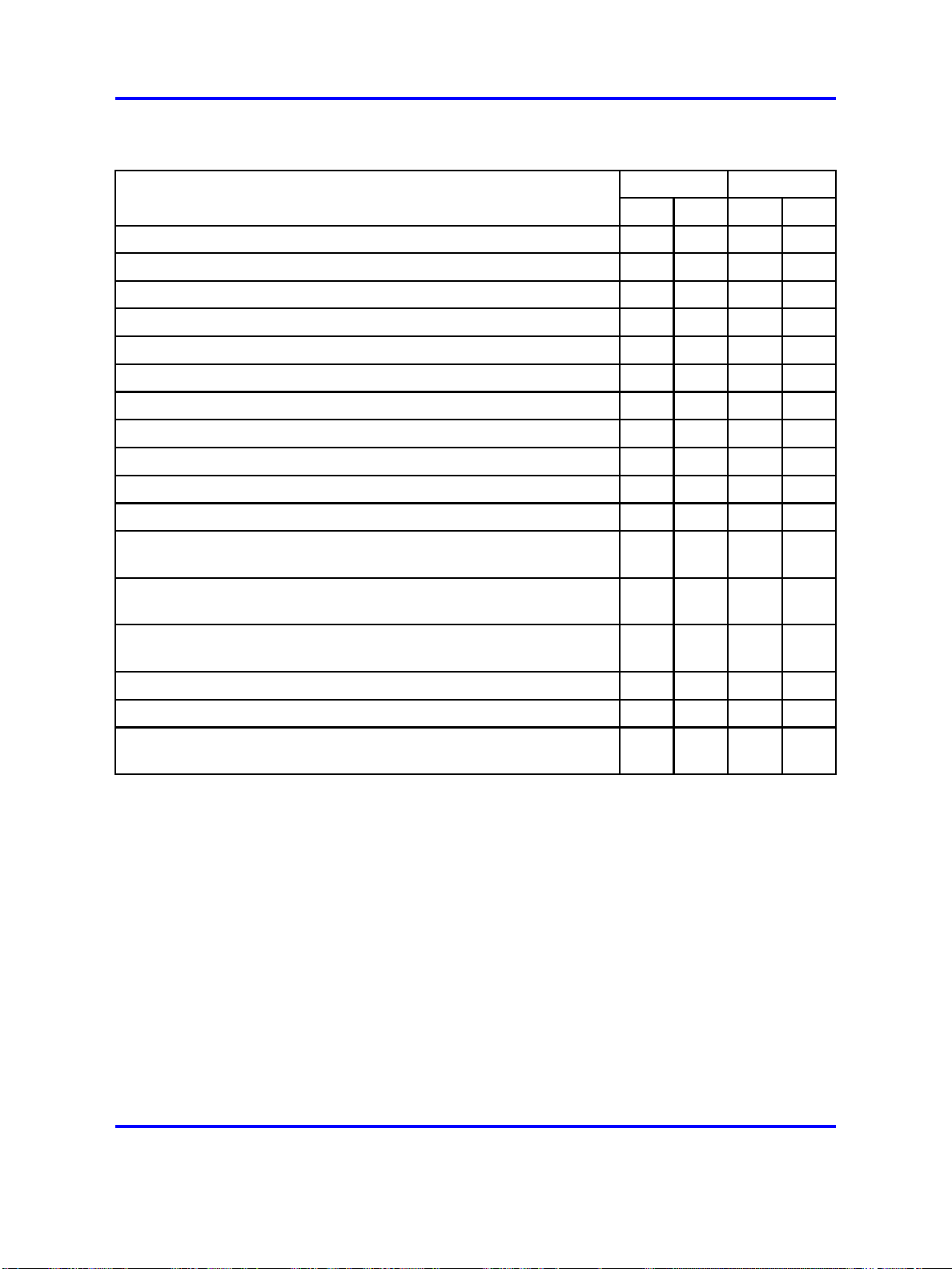
Each of the line cards was designed to fit a specific system need. Table 1
"Line card characteristics" (page 18) lists the line card characteristics.
Table 1
Line card characteristics
Part
Number Description Lines
NT1R20 Off-premise
station analog
line card
NT5D11 Lineside T1
Interface card
NT5D33/34Lineside E1
Interface card
8
24
30
Supervised
Line
Type
Analog Interrupted dial
T1 None Yes IPE
E1 None Yes IPE
Message
Waiting
tone
Analog
Lines Architecture
Yes IPE
NT8D02 Digital Line
card (16
voice/16 data)
NT8D09 Analog
Message
Waiting Line
card
NT1R20 Off-Premise Station Analog Line card
The NT1R20 Off-Premise Station (OPS) Analog Line card is an intelligent
eight-channel analog line card designed to be used with 2-wire analog
terminal equipment such as analog (500/2500-type) telephones and analog
modems. Each line has integral hazardous and surge voltage protection
to protect the system from damage due to lightning strikes and accidental
power line connections. This card is normally used whenever the phone
lines leave the building in which the switch is installed. The OPS line card
supports message waiting notification by interrupting the dial tone when
the receiver is first picked up. It also provides battery reversal answer and
disconnect analog line supervision and hook flash disconnect analog line
supervision features.
16
16
Digital Message
waiting signal
forwarded to
digital phone
for display
Analog Lamp No IPE
No IPE
Copyright © 2003-2008 Nortel Networks
.
Nortel Communication Server 1000
Circuit Card Reference
NN43001-311 02.06 Standard
27 August 2008
Page 19

Line cards 19
NT5D11 and NT5D14 Lineside T1 interface card
The NT5D11/14 Lineside T1 Interface card is an intelligent 24-channel
digital line card that is used to connect the switch to T1-compatible
terminal equipment on the lineside. The T1-compatible terminal equipment
includes voice mail systems, channel banks containing FXS cards, and
key systems such as the Nortel Norstar. The Lineside T1 card differs
from trunk T1 cards in that it supports terminal equipment features such
as hook-flash, transfer, hold, and conference. It emulates an analog line
card to the system software.
NT5D33 and NT5D34 Lineside E1 Interface card
The NT5D33/34 Lineside E1 Interface card is an intelligent 30-channel
digital line card that is used to connect the switch to E1-compatible
terminal equipment on the lineside. The E1-compatible terminal equipment
includes voice mail systems. The lineside E1 card emulates an analog line
card to the system software.
NT8D02 Digital Line card
The NT8D02 Digital Line card is an intelligent 16-channel digital line card
that provides voice and data communication links between a CS 1000E,
CS 1000M, and Meridian 1switch and modular digital telephones. Each of
the 16 channels support voice-only or simultaneous voice and data service
over a single twisted pair of standard telephone wire.
NT8D09 analog message waiting line card
The NT8D09 Analog Message Waiting Line card is an intelligent
16-channel analog line card designed to be used with 2-wire terminal
equipment such as analog (500/2500-type) telephones, modems, and key
systems. This card can also provide a high-voltage, low-current signal on
the Tip and Ring pair of each line to light the message waiting lamp on
phones equipped with that feature.
Installation
This section provides a high-level description of how to install and test line
cards.
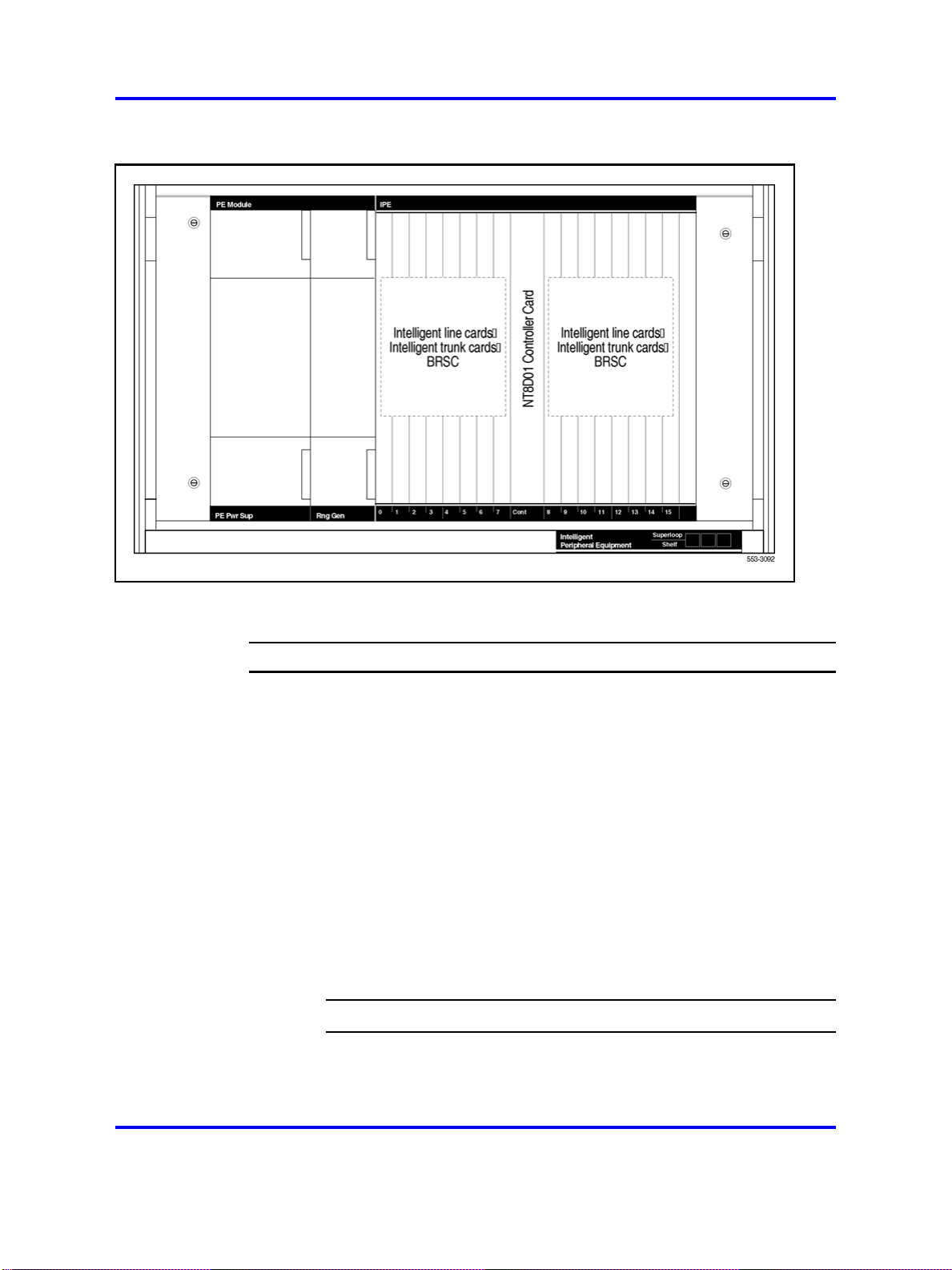
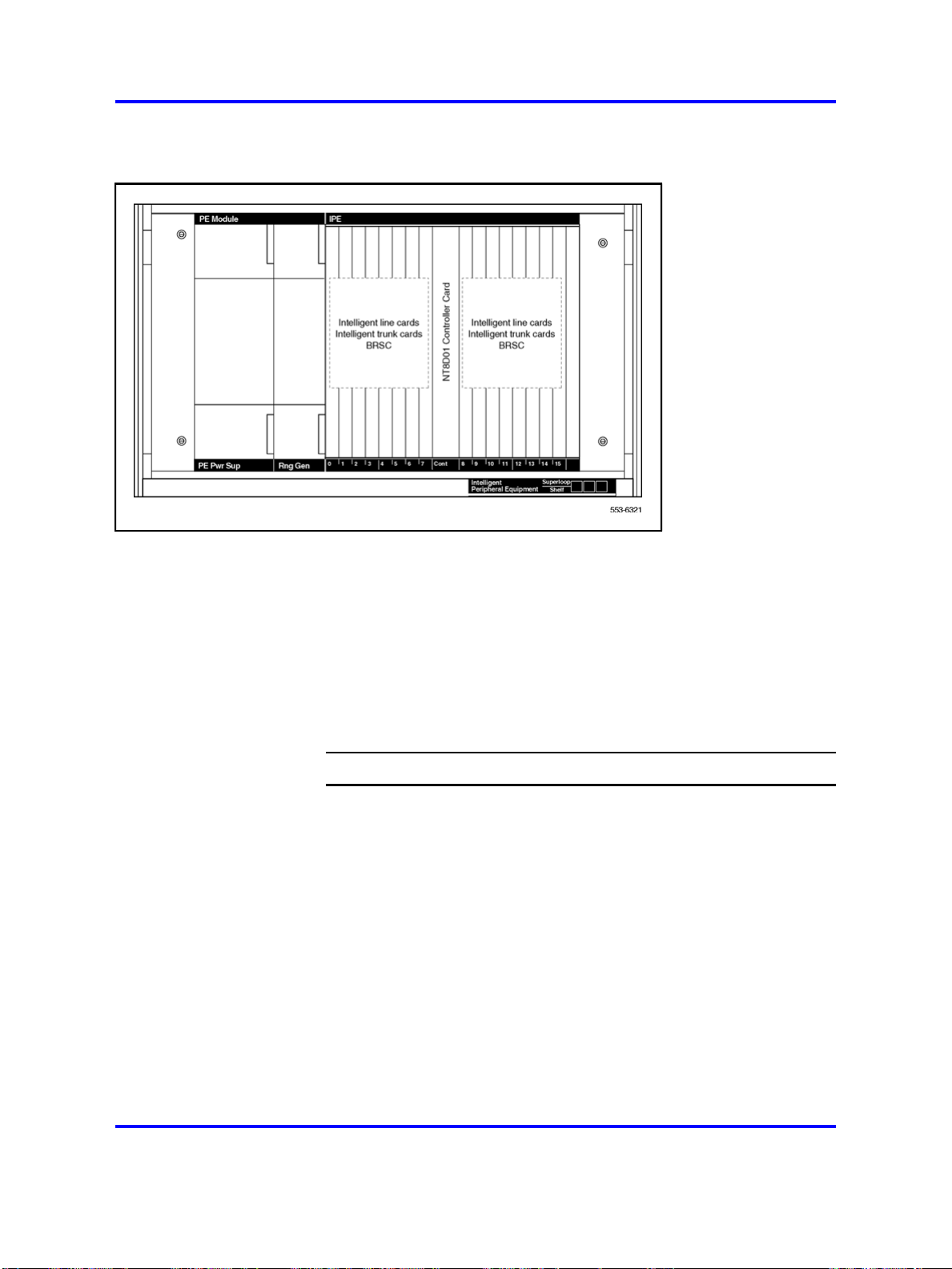
IPE line cards can be installed in any slot of the NT8D37 IPE module.
Figure 1 "IPE line cards shown installed in an NT8D37 IPE module" (page
20) shows where an IPE line card can be installed in an NT8D37 IPE
module.
Copyright © 2003-2008 Nortel Networks
.
Nortel Communication Server 1000
Circuit Card Reference
NN43001-311 02.06 Standard
27 August 2008
Page 20
20 Overview
Figure 1
IPE line cards shown installed in an NT8D37 IPE module
When installing line cards, follow these general procedures:
Step Action
1 Configure the jumpers and switches on the line card (if any) to
meet system needs.
2 Install the line card into the selected slot.
3 Install the cable that connects the backplane connector on the
IPE module to the module I/O panel.
4 Connect a 25-pair cable from the module I/O panel connector to
the Main Distribution Frame (MDF).
5 Connect the line card output to the selected terminal equipment
at the MDF.
6 Configure the individual line interface unit using the Analog
(500/2500-type) Telephone Administration program LD
10 for analog line interface units and Multi-line Telephone
Administration program LD 11 for digital line interface units.
--End--
Once these steps are complete, the terminal equipment is ready for use.
Copyright © 2003-2008 Nortel Networks
.
Nortel Communication Server 1000
Circuit Card Reference
NN43001-311 02.06 Standard
27 August 2008
Page 21

Operation
This section describes how line cards fit into the CS 1000E, CS 1000M,
and Meridian 1architecture, the busses that carry signals to and from the
line cards, and how they connect to terminal equipment. These differences
are summarized in Table 2 "IPE module architecture" (page 21).
Host interface bus
Cards based on the IPE bus use a built-in microcontroller. The IPE
microcontroller is used to do the following:
•
• configure the card according to instructions issued by the system
•
Table 2
IPE module architecture
Parameter IPE
Line cards 21
perform local diagnostics (self-test)
report back to the system information such as card identification
(type, vintage, and serial number), firmware version, and programmed
configuration status)
Card Dimensions 31.75 x 25.4 x 2.2 cm (12.5 x10.0 x 0.875
in.).
Network Interface DS-30X Loops
Communication Interface card LAN Link
Microcontroller 8031/8051 Family
Peripheral Interface card NT8D01 Controller card
Network Interface card NT8D04 Superloop Network card
Modules NT8D37 IPE module
Intelligent Peripheral Equipment
IPE line cards all share a similar architecture. Figure 2 "Typical IPE analog
line card architecture" (page 23) shows a typical IPE line card architecture.
The various line cards differ only in the number and types of line interface
units.
The switch communicates with IPE modules over two separate interfaces.
Voice and signaling data are sent and received over DS-30X loops, and
maintenance data is sent over a separate asynchronous communication
link called the card LAN link.
Copyright © 2003-2008 Nortel Networks
.
Nortel Communication Server 1000
Circuit Card Reference
NN43001-311 02.06 Standard
27 August 2008
Page 22

22 Overview
Signaling data is information directly related to the operation of the
telephone line. Some examples of signaling commands include:
•
off-hook/on-hook
•
ringing signal on/off
• message waiting lamp on/off
Maintenance data is data relating to the configuration and operation of
the IPE card, and is carried on the card LAN link. Some examples of
maintenance data include:
•
polling
• reporting of self-test status
• CP initiated card reset
•
reporting of card ID (card type and hardware vintage)
• reporting of firmware version
•
downloading line interface unit parameters
•
reporting of line interface unit configuration
•
enabling/disabling of the DS-30X network loop bus
• reporting of card status or T1 link status
Copyright © 2003-2008 Nortel Networks
.
Nortel Communication Server 1000
Circuit Card Reference
NN43001-311 02.06 Standard
27 August 2008
Page 23
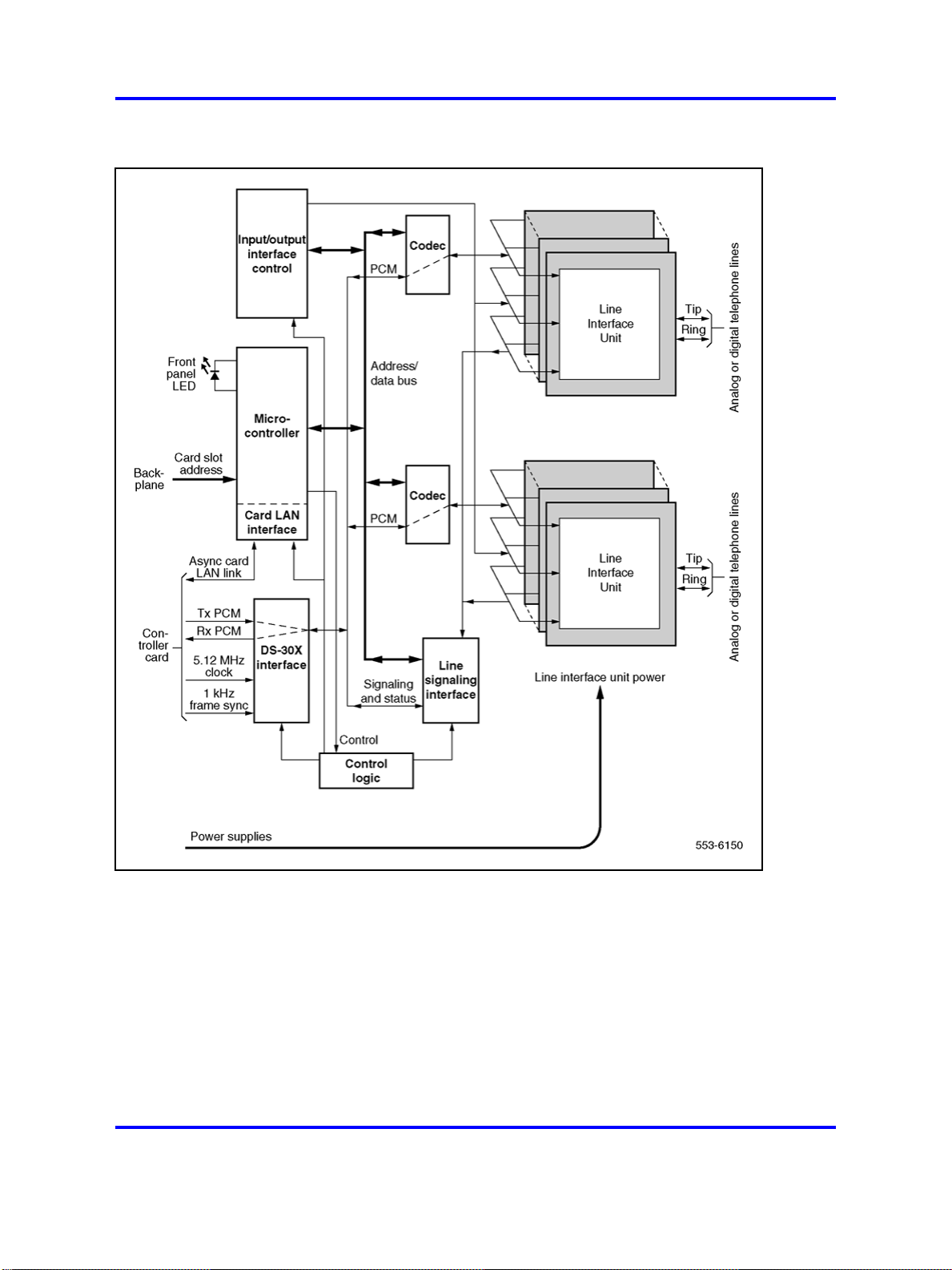
Figure 2
Typical IPE analog line card architecture
Line cards 23
DS-30X loops The line interfaces provided by the line cards connect
to conventional 2-wire (tip and ring) line facilities. IPE analog line cards
convert the incoming analog voice and signaling information to digital form
and route it to the Call Server over DS-30X network loops. Conversely,
digital voice and signaling information from the Call Server is sent over
DS-30X network loops to the analog line cards where it is converted to
analog form and applied to the line facility.
Copyright © 2003-2008 Nortel Networks
.
Nortel Communication Server 1000
Circuit Card Reference
NN43001-311 02.06 Standard
27 August 2008
Page 24

24 Overview
IPE digital line cards receive the data from the digital phone terminal
as 512 kHz Time Compressed Multiplexed (TCM) data. The digital line
card converts that data to a format compatible with the DS-30X loop and
transmits it in the next available timeslot. When a word is received from
the DS-30X loop, the digital line card converts it to the TCM format and
transmits it to the digital phone terminal over the digital line facility.
A separate dedicated DS-30X network loop is extended between each IPE
line/trunk card and the controller cards within an IPE module. A DS-30X
network loop is composed of two synchronous serial data buses. One bus
transports in the Transmit (Tx) direction towards the line facility and the
other in the Receive (Rx) direction towards the CS 1000E, CS 1000M, and
Meridian 1.
Each bus has 32 channels for Pulse Code Modulated (PCM) voice data.
Each channel consists of a 10-bit word. See Figure 3 "DS-30X loop data
format" (page 25). Eight of the 10 bits are for PCM data, one bit is the call
signaling bit, and the last bit is a data valid bit. The eight-bit PCM portion
of a channel is called a timeslot. The DS-30X loop is clocked at 2.56 Mbps
(one-half the 5.12 MHz clock frequency supplied by the controller card).
The timeslot repetition rate for a single channel is 8 kHz. The controller
card also supplies a locally generated 1 kHz frame sync signal for channel
synchronization.
Signaling data is transmitted to and from the line cards using the call
signaling bit within the 10-bit channel. When the line card detects
a condition that the switch needs to know about, it creates a 24-bit
signaling word. This word is shifted out on the signaling bit for the
associated channel one bit at a time during 24 successive DS-30X frames.
Conversely, when the switch sends signaling data to the line card, it is sent
as a 24-bit word divided among 24 successive DS-30X frames.
Copyright © 2003-2008 Nortel Networks
.
Nortel Communication Server 1000
Circuit Card Reference
NN43001-311 02.06 Standard
27 August 2008
Page 25
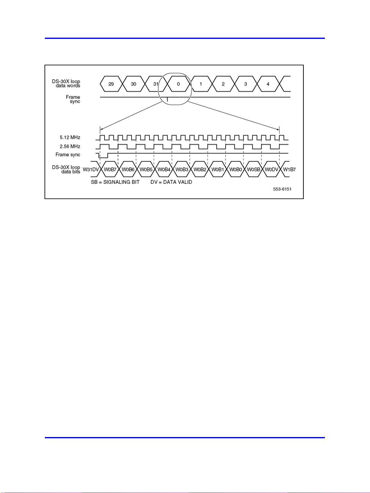
Figure 3
DS-30X loop data format
DS-30Y network loops extend between controller cards and superloop
network cards in the Common Equipment (CE). They function in a manner
similar to DS-30X loops. See Figure 5 "Digital line interface unit block
diagram" (page 29).
Line cards 25
A DS-30Y loop carries the PCM timeslot traffic of a DS-30X loop. Four
DS-30Y network loops form a superloop with a capacity of 128 channels
(120 usable timeslots). See Communication Server 1000M and Meridian
1 Large System Planning and Engineering (NN43021-220) for more
information on superloops.
Card LAN link Maintenance communication is the exchange of control
and status data between IPE line or trunk cards and the Call Server by
way of the NT8D01 Controller card. Maintenance data is transported
through the card LAN link. This link is composed of two asynchronous
serial buses (called the Async card LAN link in Figure 2 "Typical IPE
analog line card architecture" (page 23)). The output bus is used by the
system controller for output of control data to the line card. The input bus
is used by the system controller for input of line card status data.
A card LAN link bus is common to all of the line/trunk card slots within
an IPE module. This bus is arranged in a master/slave configuration
where the controller card is the master and all other cards are slaves.
The module backplane provides each line/trunk card slot with a unique
hardwired slot address. This slot address enables a slave card to respond
when addressed by the controller card. The controller card communicates
with only one slave at a time.
Copyright © 2003-2008 Nortel Networks
.
Nortel Communication Server 1000
Circuit Card Reference
NN43001-311 02.06 Standard
27 August 2008
Page 26

26 Overview
Analog line interface units
In normal operation, the controller card continually scans (polls) all of the
slave cards connected to the card LAN to monitor their presence and
operational status. The slave card sends replies to the controller on the
input bus along with its card slot address for identification. In its reply,
the slave informs the controller if any change in card status has taken
place. The controller can then prompt the slave for specific information.
Slaves only respond when prompted by the controller; they do not initiate
exchange of control or status data on their own.
When an IPE line card is first plugged into the backplane, it runs a
self-test. When the self-test is completed, a properly functioning card
responds to the next controller card poll with the self-test status. The
controller then queries for card identification and other status information.
The controller then downloads all applicable configuration data to the line
card, initializes it, and puts it into an operational mode.
Once the 8-bit digital voice signal has been received by the analog line
card, it must be converted back into an analog signal, filtered, converted
from a 4-wire transmission path to a 2-wire transmission path, and driven
onto the analog telephone line.
Figure 4 "Typical analog line interface unit block diagram" (page 27) shows
a typical example of the logic that performs these functions. Each part of
the analog line interface unit is discussed in the following section.
Copyright © 2003-2008 Nortel Networks
.
Nortel Communication Server 1000
Circuit Card Reference
NN43001-311 02.06 Standard
27 August 2008
Page 27
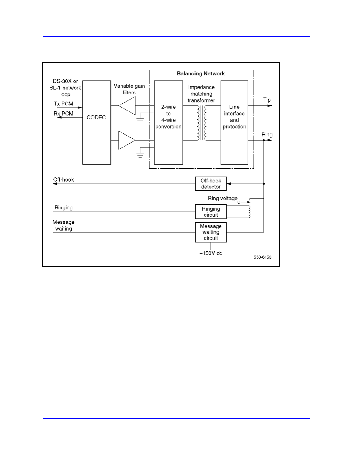
Figure 4
Typical analog line interface unit block diagram
Line cards 27
Coder/Decoder circuit
The Coder/Decoder (CODEC) performs Analog to Digital (A/D) and Digital
to Analog (D/A) conversion of the line analog voiceband signal to and from
a digital PCM signal. This signal can be coded and decoded using either
the A-Law or the µ-Law companding algorithm.
On some analog line cards, the decoding algorithm depends of the type
of CODEC installed when the board is built. On others, it is an option
selected using a software overlay.
Variable gain filters
Audio signals received from the analog phone line are passed through a
low-pass A/D monolithic filter that limits the frequency spread of the input
signal to a nominal 200 to 3400 Hz bandwidth. The audio signal is then
applied to the input of the CODEC. Audio signals coming from the CODEC
are passed through a low-pass A/D monolithic filter that integrates the
amplitude modulated pulses coming from the CODEC, and then filters and
Copyright © 2003-2008 Nortel Networks
Nortel Communication Server 1000
Circuit Card Reference
NN43001-311 02.06 Standard
27 August 2008
.
Page 28

28 Overview
amplifies the result. On some of the line cards, the gain of these filters can
be programmed by the system controller. This allows the system to make
up for line losses according to the loss plan.
Balancing network
3
Depending on the card type, the balancing network provides a 600
3
/4, 3COM or 3CM2 impedance matching network. It also converts
900
/4,
the 2-wire transmission path (tip and ring) to a 4-wire transmission
path (Rx/ground and Tx/ground). The balancing network is usually
a transformer/analog (hybrid) circuit combination, but can also be a
monolithic Subscriber Line Interface Circuit (SLIC) on the newer line cards.
Line interface and foreign voltage protection
The line interface unit connects the balancing network to the telephone
tip and ring pairs. The off-premise line card (NT1R20) has circuitry that
protects the line card from foreign voltage surges caused by accidental
power line connections and lightning surges. This protection is necessary
if the telephone line leaves the building where the switch is installed.
The line interface unit has a relay that applies the ringing voltage onto
the phone line. See Figure 4 "Typical analog line interface unit block
diagram" (page 27). The RSYNC signal from the 20 Hz (nominal) ringing
voltage power supply is used to prevent switching of the relay during the
current peak. This eliminates switching glitches and extends the life of the
switching relay.
The off-hook detection circuit monitors the current draw on the phone line.
When the current draw exceeds a preset value, the circuit generates an
off-hook signal that is transmitted back to the system controller.
The message waiting circuit on message waiting line cards monitors the
status of the message waiting signal and applies –150 V dc power to the
tip lead when activated. This voltage is used to light the message waiting
lamps on phones that are equipped with that feature. The high voltage
supply is automatically disconnected when the phone goes off-hook.
Newer line cards can sense when the message waiting lamp is not
working and can report that information back to the system controller.
Digital line interface units
The NT8D02 Digital Line card provides voice and data communication
links between a switch and modular digital telephones. These lines
carry multiplexed PCM voice, data and signaling information as Time
Compression Multiplexed (TCM) loops. Each TCM loop can be connected
to a Nortel "Meridian Modular Digital" telephone.
Copyright © 2003-2008 Nortel Networks
Nortel Communication Server 1000
Circuit Card Reference
NN43001-311 02.06 Standard
27 August 2008
.
Page 29
Line cards 29
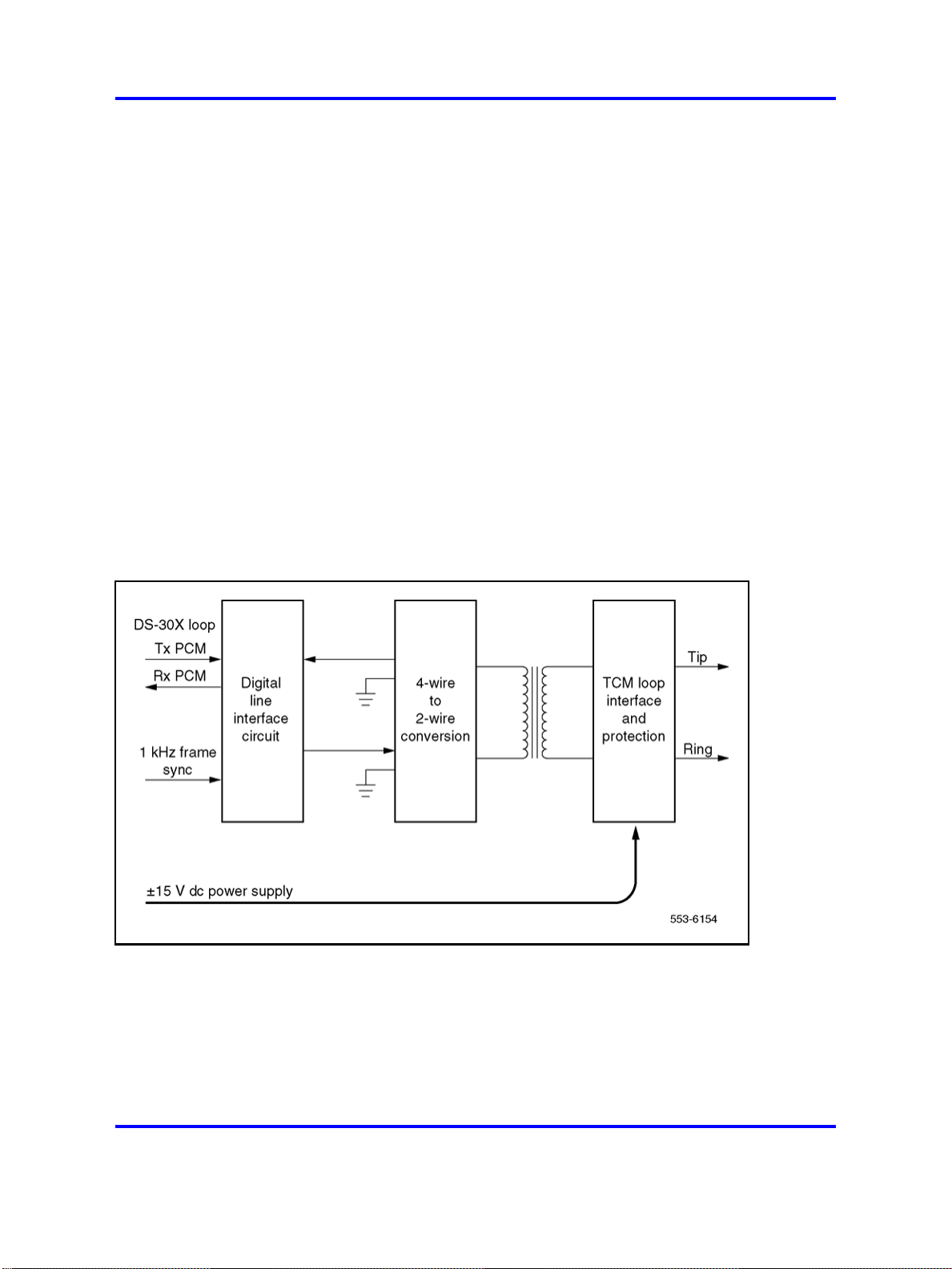
The digital line interface card contains one or more digital line interface
units. See Figure 5 "Digital line interface unit block diagram" (page 29).
Each digital line interface unit contains a Digital Line Interface Circuit
(DLIC). The purpose of each DLIC is to demultiplex data from the DS-30X
Tx channel into integrated voice and data bitstreams and transmit
those bitstreams as Bi-Polar Return to Zero, Alternate Mark Inversion
(BPRZ-AMI) data to the TCM loop. It also does the opposite: receives
BPRZ-AMI bitstreams from the TCM loop and multiplexes the integrated
voice and data bitstream onto the DS-30X Rx channel.
The 4-wire to 2-wire conversion circuit converts the 2-wire tip and ring
leads into a 4-wire (Tx and ground and RX and ground) signal that is
compatible with the digital line interface circuit.
TCM loop interfaces
Each digital phone line terminates on the digital line card at a TCM loop
interface circuit. The circuit provides transformer coupling and foreign
voltage protection between the TCM loop and the digital line interface
circuit. It also provides power for the digital telephone.
Figure 5
Digital line interface unit block diagram
To prevent undesirable side effects from occurring when the TCM loop
interface cannot provide the proper signals on the digital phone line, the
system controller can remove the ±15 V dc power supply from the TCM
loop interface. This happens when either the card gets a command from
the NT8D01 Controller card to shut down the channel, or when the digital
line card detects a loss of the 1 KHz frame synchronization signal.
Copyright © 2003-2008 Nortel Networks
.
Nortel Communication Server 1000
Circuit Card Reference
NN43001-311 02.06 Standard
27 August 2008
Page 30

30 Overview
Analog line call operation
Each TCM loop interface circuit can service loops up to 3500 ft. in length
when using 24 gauge wire. The circuit allows for a maximum ac signal loss
of 15.5 dB at 256 KHz and a maximum DC loop resistance of 210 ohms.
Signaling
The digital line interface units also contain signaling and control circuits
that establish, monitor, and take down call connections. These circuits
work with the system controller to operate the digital line interface circuits
during calls. The circuits receive outgoing call signaling messages from
the controller and return incoming call status information to the controller
over the DS-30X network loop.
The applications, features, and signalling arrangements for each line
interface unit are configured in software and implemented on the card
through software download messages. When an analog line interface unit
is idle, it provides a voltage near ground on the tip lead and a voltage near
–48 V dc on the ring lead to the near-end station. (The near-end station is
the telephone or device that is connected to the analog line card by the tip
and ring leads.) An on-hook telephone presents a high impedance toward
the line interface unit on the card.
Incoming calls
Incoming calls to a telephone that is connected to an analog line card
can originate either from stations that are local (served by the PBX), or
remote (served through the Public Switched Telephone Network (PSTN)).
The alerting signal to a telephone is 20 Hz (nominal) ringing. When
an incoming call is answered by the near-end station going off-hook, a
low-resistance dc loop is placed across the tip and ring leads (towards the
analog line card) and ringing is tripped. See Figure 6 "Call connection
sequence - near-end station receiving call" (page 31).
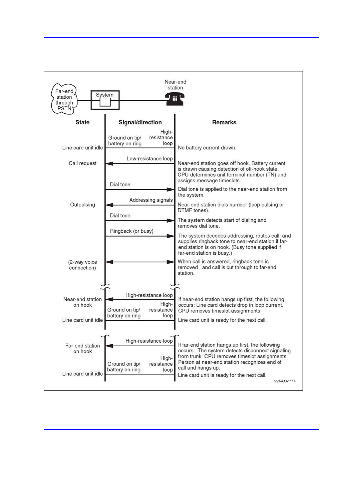
Outgoing calls
For outgoing calls from the near-end station, a line interface unit is seized
when the station goes off-hook, placing a low-resistance loop across
the tip and ring leads towards the analog line card. See Figure 7 "Call
connection sequence - near-end originating call" (page 32). When the card
detects the low-resistance loop, it prepares to receive digits. When the
system is ready to receive digits, it returns dial tone. Outward address
signaling is then applied from the near-end station in the form of loop
(interrupting) dial pulses or DTMF tones.
Copyright © 2003-2008 Nortel Networks
.
Nortel Communication Server 1000
Circuit Card Reference
NN43001-311 02.06 Standard
27 August 2008
Page 31
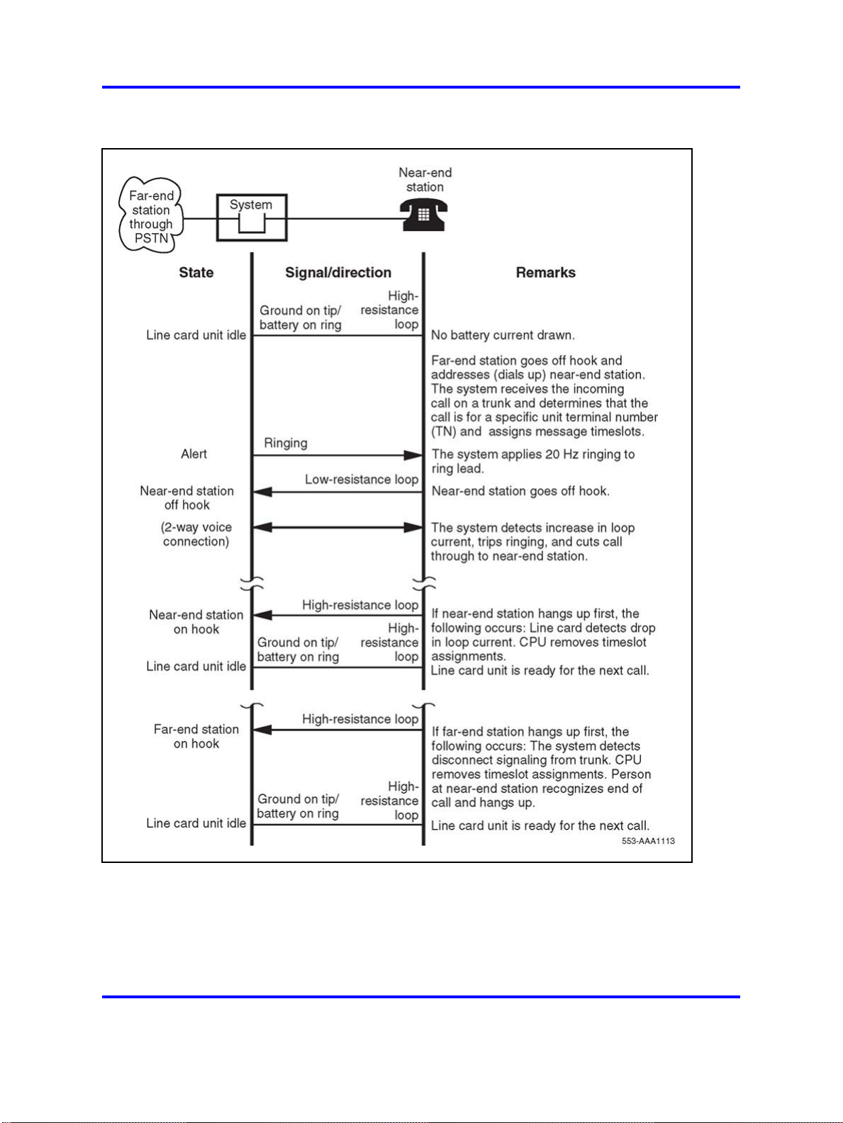
Figure 6
Call connection sequence - near-end station receiving call
Line cards 31
Copyright © 2003-2008 Nortel Networks
.
Nortel Communication Server 1000
Circuit Card Reference
NN43001-311 02.06 Standard
27 August 2008
Page 32
32 Overview
Figure 7
Call connection sequence - near-end originating call
Copyright © 2003-2008 Nortel Networks
.
Nortel Communication Server 1000
Circuit Card Reference
NN43001-311 02.06 Standard
27 August 2008
Page 33

Line cards 33
Message waiting
Line cards that are equipped with the message waiting feature receive
notification that a message is waiting across the Card LAN link (IPE
cards). On cards that drive a message waiting light, the light is turned on
by connecting the ring side of the telephone line to the –150 V dc power
supply. When the line card senses that the telephone has gone off-hook,
it removes the –150 V dc voltage until the telephone goes back on-hook.
Line cards that use an interrupted dial tone to indicate message waiting do
nothing until the receiver is picked up. The line card then interrupts the dial
tone at a regular interval to indicate that a message is waiting.
In both cases, the message waiting indication continues until the user
checks his or her messages. At that time, the system cancels the message
waiting indication by sending another message across the Card LAN link
or network loop.
Analog line supervision
Analog line supervision features are used to extend the answer
supervision and disconnect supervision signals when the line card is
connected to an intelligent terminal device (Key system or intelligent pay
phone). Two types of analog line supervision are provided:
• battery reversal answer and disconnect supervision
•
hook flash disconnect supervision
Battery reversal answer and disconnect supervision Battery reversal
answer and disconnect supervision is only used for calls that originate
from the terminal device. It provides both far-end answer supervision
and far-end disconnect supervision signals to the terminal device. In an
intelligent pay phone application, these signals provide the information
necessary to accurately compute toll charges.
In the idle state, and during dialing and ringing at the far end, the line card
provides a ground signal on the tip lead and battery on the ring lead. See
Figure 8 "Battery reversal answer and disconnect supervision sequence"
(page 35). When the far-end answers, these polarities are reversed.
The reversed battery connection is maintained as long as the call is
established. When the far-end disconnects, the system sends a message
that causes the line card to revert the battery and ground signals to the
normal state to signal that the call is complete.
Hook Flash disconnect supervision Hook flash disconnect supervision
is only used for incoming calls that terminate at the terminal device
(typically a Key system). See Figure 9 "Hook flash disconnect supervision
sequence" (page 36). The disconnect signal is indicated by the removal
Copyright © 2003-2008 Nortel Networks
.
Nortel Communication Server 1000
Circuit Card Reference
NN43001-311 02.06 Standard
27 August 2008
Page 34

34 Overview
Digital line call operation
Lineside T1 and E1 call operation
of the ground connection to the tip lead for a specific length of time. The
length of time is programmed in LD10, and ranges from a minimum of 10
milliseconds to a maximum of 2.55 seconds. See
Software Input/Output
Reference — Administration (NN43001-611) for more information.
Digital line call operation is controlled entirely by use of messages between
the digital telephone and the system. These messages are carried across
the TCM loop interface. There is no call connection sequence similar to
the one used for analog telephone line operation.
The lineside T1/E1 card’s call operation is performed differently depending
on whether the T1/E1 link is configured to process calls in loop start mode
or ground start mode. Configuration is performed through dip switch
settings on the lineside T1/E1 card.
The lineside T1/E1 card performs calls processing separately on each of
its 24 channels. Signaling is performed using the "A/B robbed bit" signaling
standard for T1/E1 communication.
A/B robbed bit signaling simulates standard analog signaling by sending a
meaningful combination of ones and zeros across the line that correlates
to the electrical impulses that standard analog signaling sends. For
example, to represent that an analog line interface unit is idle, the analog
line card provides a ground on the tip lead and –48Vdc on the ring lead.
The lineside T1/E1 card accomplishes the same result by sending its A bit
as 0 (translated as ground on the tip lead) and its B bit as 1 (translated
as –48V dc on the ring lead). However, measuring the voltage of the ring
lead on the T1/E1 line would not return –48V dc, since actual electrical
impulses are not being sent.
Copyright © 2003-2008 Nortel Networks
.
Nortel Communication Server 1000
Circuit Card Reference
NN43001-311 02.06 Standard
27 August 2008
Page 35
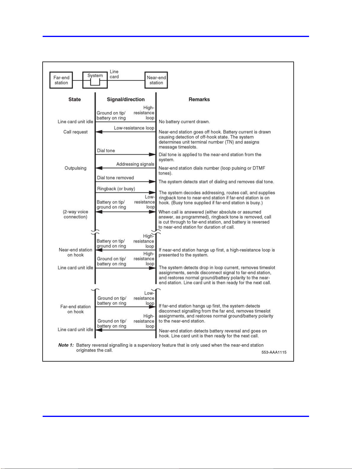
Figure 8
Battery reversal answer and disconnect supervision sequence
Line cards 35
Copyright © 2003-2008 Nortel Networks
.
Nortel Communication Server 1000
Circuit Card Reference
NN43001-311 02.06 Standard
27 August 2008
Page 36

36 Overview
Figure 9
Hook flash disconnect supervision sequence
Call operation is described by categorizing the operation into the following
main states:
Copyright © 2003-2008 Nortel Networks
.
Nortel Communication Server 1000
Circuit Card Reference
NN43001-311 02.06 Standard
27 August 2008
Page 37

Line cards 37
• Idle (on-hook)
• Incoming calls
• Outgoing calls
•
Calls disconnected by the CO
• Calls disconnected by the telephone
Loop Start Mode
In Loop Start mode, the A and B bits meaning is:
•
Transmit from LTI:A bit = 0 (tip ground on); B bit = Ringing (0=on,
1=off)
• Receive to LTI: A bit = Loop (0=open, 1=closed); B bit = 1 (no ring
ground)
When a T1 channel is idle, the Lineside T1 card simulates a ground on the
tip lead and –48Vdc on the ring lead to the terminal equipment by setting
its transmit A bit to 0 and transmit B bit to 1. Accordingly, an on-hook
channel on the terminal equipment simulates an open loop toward the
Lineside T1 card, causing the Lineside T1 card’s receive bits to be set to A
= 0 and receive B = 1.
Incoming calls Incoming calls to terminal equipment attached to the
Lineside T1 card can originate either from stations that are local (served
by the PBX), or remote (served through the PSTN). To provide the ringing
signal to a telephone the Lineside T1 card simulates an additional 90V on
the ring lead to the terminal equipment by alternating the transmit B bit
between 0 and 1 (0 during ring on, 1 during ring off). When an incoming
call is answered by the terminal equipment going off-hook, the terminal
equipment simulates tripping the ringing and shutting off ringing, causing
the Lineside T1 card’s receive A bit to be changed from 0 to 1.
Outgoing calls During outgoing calls from the terminal equipment,
a channel is seized when the station goes off-hook. This simulates a
low-resistance loop across the tip and ring leads toward the Lineside
T1 card, causing the lineside T1’s receive A bit to be changed from 0 to
1. This bit change prepares the Lineside T1 to receive digits. Outward
address signaling is then applied from the terminal equipment in the form
of DTMF tones or loop (interrupting) dial pulses that are signaled by the
receive A bit pulsing between 1 and 0.
Call disconnect from far end PSTN, private network or local
Station When a call is in process, the central office may disconnect the
call from the CS 1000E, CS 1000M, and Meridian 1. If the Lineside T1
port has been configured with the supervised analog line (SAL) feature,
Copyright © 2003-2008 Nortel Networks
.
Nortel Communication Server 1000
Circuit Card Reference
NN43001-311 02.06 Standard
27 August 2008
Page 38

38 Overview
the Lineside T1 card responds to the distant end disconnect message
by momentarily changing its transmit A bit to 1 and then returning it to 0.
The duration of time that the transmit A bit remains at 1 before returning
to 0 depends upon the setting that was configured using the SAL. If
the terminal equipment is capable of detecting distant end disconnect,
it responds by changing the Lineside T1 card’s receive A bit to 0 (open
loop).The call is now terminated and the interface is in the idle (on-hook)
state.
For the Lineside T1 card to support distant end disconnect in loop start
mode, the following configuration parameters must exist:
•
The Supervised Analog Line (SAL) feature must be configured for each
Lineside T1 port.
Note:
loop start operation. This is configurable in 10 m/s increments.
By default, the SAL feature opens the tip side for 750 m/s in
• For outgoing trunk calls, the trunk facility must provide far end
disconnect supervision.
• In order to detect distant end disconnect for calls originating on the
Lineside T1 card, the battery reversal feature within the SAL software
must be enabled. Enabling the battery reversal feature does not
provide battery reversal indication but only provides a momentary
interruption of the tip ground by asserting the A bit to 1 for the specified
duration.
•
In order to detect distant end disconnect for calls terminating on the
Lineside T1 card, the hook flash feature within the SAL software must
be enabled.
•
In order to detect distant end disconnect for calls originating and
terminating on the Lineside T1 card, both the battery reversal and hook
flash features must be enabled within the SAL software.
Call disconnect from Lineside T1 terminal equipment Alternatively,
while a call is in process, the terminal equipment may disconnect by going
on-hook. The terminal equipment detects no loop current and sends
signaling to the Lineside T1 card that causes its receive A bit to change
from 1 to 0. The call is now released.
Table 3 "Loop Start Call Processing A/B Bit Settings" (page 39) outlines
the lineside T1’s A and B bit settings in each state of call processing.
Copyright © 2003-2008 Nortel Networks
.
Nortel Communication Server 1000
Circuit Card Reference
NN43001-311 02.06 Standard
27 August 2008
Page 39
Line cards 39
Table 3
Loop Start Call Processing A/B Bit Settings
Transmit Receive
State ABAB
Idle
Incoming Calls:
• Idle
• Ringing is applied from Lineside T1 card
•
Terminal equipment goes off-hook
• Lineside T1 card stops ringing
Outgoing Calls:
• Idle
• Terminal equipment goes off-hook
Call Disconnect from far end:
•
Steady state (call in progress)
•
Far end disconnects by dropping loop current and Lineside T1
card changes Transmit A bit to 1 momentarily.
•
Terminal equipment responds causing Receive A bit to change
to 0.
•
Lineside T1 responds by changing its Transmit A bit to 0. Call is
terminated and set to idle state.
Call disconnect from terminal equipment:
•
Steady state (call in progress)
0101
0101
0
1/0
0
1/0
0111
0101
0111
0111
1111
1101
0101
0111
01
11
•
Terminal equipment goes on-hook causing the Receive A bit to
change to 0. Call is terminated and set to idle state.
Ground Start Mode
In Ground Start mode, the A and B bits meaning is:
•
Transmit from LTI:A bit = Tip ground (0=grounded, 1=not grounded); B
bit = Ringing (0=on, 1=off)
• Receive to LTI: A bit = Loop (0=open, 1=closed); B bit = Ring ground
(0=grounded, 1=not grounded)
When a T1 channel is idle, the Lineside T1 card simulates a ground on the
tip lead and -48V dc on the ring lead to the terminal equipment by setting
the transmit A bit to 1 and transmit B bit to 1. Accordingly, an on-hook
telephone simulates an open loop toward the Lineside T1 card, causing
the Lineside T1 card’s receive bits to be set to A = 0 and B = 1.
Nortel Communication Server 1000
Circuit Card Reference
NN43001-311 02.06 Standard
Copyright © 2003-2008 Nortel Networks
27 August 2008
0101
.
Page 40

40 Overview
Incoming Calls Incoming calls to terminal equipment that is connected
to the Lineside T1 card can originate either from stations that are local
(served by the PBX), or remote (served through the public switched
telephone network). To provide the ringing signal to the terminal
equipment the Lineside T1 card simulates the 90V ring signal on the ring
lead by alternating the transmit B bit between 0 and 1 (0 during ring on,
1 during ring off), and ground on the tip lead by setting the transmit A
bit to 0. When an incoming call is answered (by the terminal equipment
going off-hook), the terminal equipment simulates tripping the ringing and
shutting off ringing by causing the lineside T1’s receive A bit to change
from 0 to 1. The Lineside T1 card responds to this message by simulating
loop closure by holding the transmit B bit constant at 1.
Outgoing Calls During outgoing calls from the terminal equipment, a
channel is seized when the terminal equipment goes off-hook, simulating a
ground to the ring lead toward the Lineside T1 card by causing the lineside
T1’s receive B bit to change from 1 to 0. In turn, the Lineside T1 card
simulates grounding its tip lead by changing the transmit A bit to 0. The
terminal equipment responds to this message by removing the ring ground
(lineside T1’s receive B bit is changed to 1) and simulating open loop at
the terminal equipment (lineside T1’s receive A bit is changed to 0).
Call disconnect from far end PSTN, private network or local
station While a call is in process, the far end might disconnect the call.
If the Lineside T1 port has been configured with the Supervised Analog
Line (SAL) feature, the Lineside T1 responds to the distant end disconnect
message by opening tip ground. This causes the Lineside T1 card to
change the transmit A bit to 1. When the terminal equipment sees the
transmit A bit go to 1, it responds by simulating open loop causing the
lineside T1’s receive A bit to change to 0. The call is terminated and the
interface is once again in the idle condition.
For the Lineside T1 card to support distant end disconnect in ground start
mode, the following configuration parameters must exist:
• The Supervised Analog Line (SAL) feature must be configured for each
Lineside T1 port.
Note: By default, the SAL feature opens the tip side for 750 m/s in
loop start operation. This is configurable in 10 m/s increments.
• In order to detect distant end disconnect for calls originating on the
Lineside T1 card, the "battery reversal" feature within the SAL software
must be enabled. Enabling the battery reversal feature does not
provide battery reversal indication when a call is answered; it only
provides battery reversal indication when a call is disconnected.
Copyright © 2003-2008 Nortel Networks
.
Nortel Communication Server 1000
Circuit Card Reference
NN43001-311 02.06 Standard
27 August 2008
Page 41
• In order to detect distant end disconnect for calls terminating on the
Lineside T1 card, the "hook flash" feature within the SAL software must
be enabled.
•
In order to detect distant end disconnect for calls originating and
terminating on the Lineside T1 card, both the "battery reversal" and
"hook flash" features within the SAL software must be enabled.
Call disconnect from Lineside T1 terminal equipment Alternatively,
while a call is in process, the terminal equipment may disconnect by
going on-hook, causing the lineside T1’s receive A bit to change to 0. The
Lineside T1 card responds to this message by simulating the removal of
ground from the tip by changing its transmit A bit to 1. The call is now
terminated and the interface is once again in the idle condition.
Table 4 "Ground Start Call Processing A/B Bit Settings" (page 41) outlines
the lineside T1’s A and B bit settings in each state of call processing.
Table 4
Ground Start Call Processing A/B Bit Settings
Line cards 41
Transmit Receive
State ABAB
Idle
Incoming Calls (to terminal equipment):
•
Idle
•
Ringing is applied from Lineside T1 card by simulating ground on
tip lead and ringing on ring lead.
•
Terminal equipment goes off-hook by simulating ground on tip
lead and ringing on ring lead.
Outgoing Calls (from terminal equipment):
•
Idle
•
Terminal equipment goes off-hook.
• The Lineside T1 simulates grounding its tip lead
• Terminal equipment opens ring ground and closes loop
Call Disconnect from far end:
• Steady state (call in progress)
• The Lineside T1 ungrounds tip
• Terminal equipment opens loop current
1101
1101
0
0/1
0
0/1
1101
1100
0100
0111
0111
1111
1101
01
11
Call disconnect from terminal equipment:
• Steady state (call in progress)
Nortel Communication Server 1000
Circuit Card Reference
NN43001-311 02.06 Standard
Copyright © 2003-2008 Nortel Networks
.
0111
27 August 2008
Page 42

42 Overview
Table 4
Ground Start Call Processing A/B Bit Settings (cont’d.)
Transmit Receive
State ABAB
•
Terminal equipment goes open loop current
• Lineside T1 card opens tip ground
Ground Start Restrictions
If the Lineside T1 card is used in ground start mode, certain restrictions
should be considered. Because the system treats the Lineside T1 card as
a standard loop start analog line card, the ground start operation of the
Lineside T1 card has operational limitations compared to typical ground
start interface equipment relating to
and glare potential.
Distant end disconnect restrictions If the SAL feature is not available
in the CS 1000 software, the Lineside T1 card is not capable of indicating
to the Customer Premise Equipment (CPE) when a call is terminated by
the distant end. In this case, the Lineside T1 card continues to provide
a grounded tip indication (A=0) to the CPE until it detects an open loop
indication (A=0) from the CPE, at which time it provides an open tip
indication (A=1). Therefore, without SAL software, the Lineside T1 card is
not capable of initiating the termination of a call to the CPE.
With the SAL software configured for each Lineside T1 line, the Lineside
T1 card provides an open tip indication to the CPE when it receives an
indication of supervised analog line from the system. This provides normal
ground start protocol call termination.
0101
1101
start of dialing, distant end disconnect
Glare restrictions In telephone lines or trunks, glare occurs when a
call origination attempt results in the answering of a terminating call that
is being presented by the far end simultaneously with the call origination
attempt by the near end.
The Lineside T1 detects presentation of a terminating call (outgoing to
Lineside T1 terminal equipment) by detecting ringing voltage. If application
of the ringing voltage is delayed due to traffic volume and ringing generator
capacity overload, the Lineside T1 ground start operation cannot connect
the tip side to ground to indicate the line has been seized by the system.
In ground start mode, glare conditions need to be considered if both
incoming and outgoing calls to the Customer Premise Equipment (CPE)
are going to be encountered. If the system and the CPE simultaneously
Copyright © 2003-2008 Nortel Networks
Nortel Communication Server 1000
Circuit Card Reference
NN43001-311 02.06 Standard
27 August 2008
.
Page 43

attempt to use a Lineside T1 line, the system completes the call
termination. It does not back down and allow the CPE to complete the call
origination, as in normal ground start operation.
If both incoming and outgoing calls are to be handled through the Lineside
T1 interface, separate channels should be configured in the system and
the CPE for each call direction. This eliminates the possibility of glare
conditions on call origination.
Voice frequency audio level
The digital pad for Lineside T1 card audio level is fixed for all types of call
connection (0 dB insertion loss in both directions), and differs from the
analog line. Audio level adjustments, if required, must be made in the
Lineside T1 terminal equipment.
Off-premise line protection
Off-premise applications are installations where the telephone lines are
extended outside the building where the PBX system is housed, but the
lines are not connected to public access facilities. This application is
commonly referred to as a "campus installation."
Line cards 43
In off-premise applications, special protection devices and grounding are
required to protect PBX and telephone components from any abnormal
conditions, such as lightning strikes and power line crosses.
The NT1R20 Off-Premise Station Line card has built-in protection against
lightning strikes and power line crosses. These should be the preferred
cards for an off-premise application. Other cards can be used when
external line protectors are installed.
When using the Lineside T1 card for an off-premise or network application,
external line protectors must be installed. Install an isolated type Channel
Service Unit (CSU) as part of the terminal equipment, to provide the
necessary isolation and outside line protection. The CSU should be an
FCC part 68 or CSA certified unit.
Line protectors
Line protectors are voltage-absorbing devices that are installed at the
cross-connect terminals at both the main building and the remote building.
The use of line protectors ensure that system and telephone components
are not damaged from accidental voltages that are within the limit of
the capacity of the protection device. Absolute protection from lightning
strikes and other stray voltages cannot be guaranteed, but the use of line
protection devices significantly reduces the possibility of damage.
Copyright © 2003-2008 Nortel Networks
.
Nortel Communication Server 1000
Circuit Card Reference
NN43001-311 02.06 Standard
27 August 2008
Page 44
44 Overview
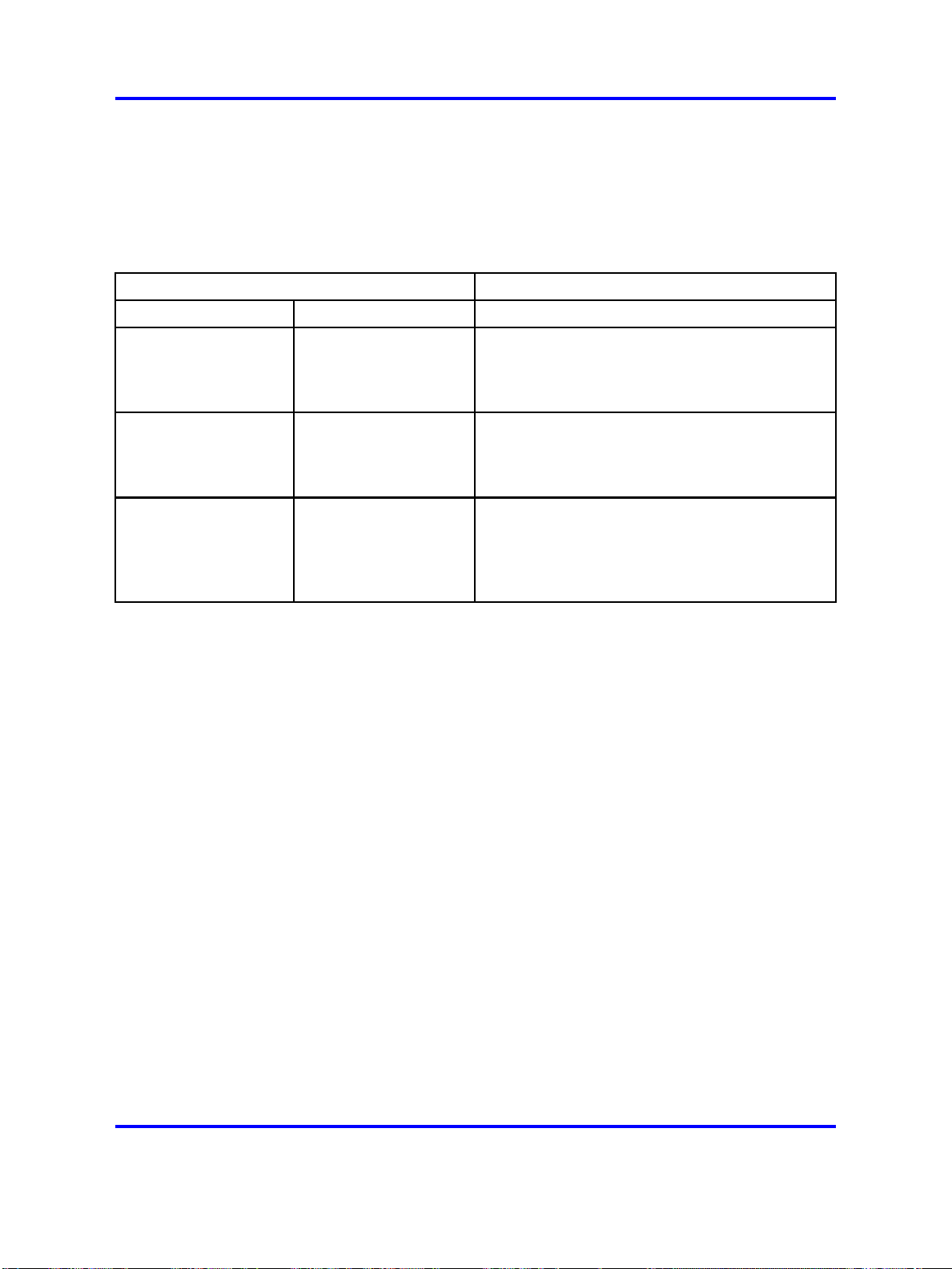
Nortel has tested line protection devices from three manufacturers. See
Table 5 "Line protection device ordering information" (page 44). Each
manufacturer offers devices for protection of digital as well as analog
telephone lines.
Table 5
Line protection device ordering information
Device order code
Analog Line Digital Line Manufacturer
UP2S-235 UP2S-75 ITW Linx Communication
201 Scott Street
Elk Grove Village, IL 60007
(708) 952-8844 or (800) 336-5469
6AP 6DP Oneac Corporation
27944 North Bradley Road
Libertyville, IL 60048-9700
(800) 553-7166 or (800) 327-8801 x555
ESP-200 ESP-050 EDCO Inc. of Florida
1805 N.E. 19th Avenue
P.O. Box 1778
Ocala, FL 34478
(904) 732-3029 or (800) 648-4076
These devices are compatible with 66 type M1-50 split blocks or
equivalent. Consult the device manufacturer if more specific compatibility
information is required.
Line protection grounding
In conjunction with line protectors, proper system (PBX) grounding
is essential to minimize equipment damage. Nortel recommends
following the grounding connection requirements as described in
Communication Server 1000M and Meridian 1 Large System Installation
and Commissioning, . This requirement includes connecting the ground for
the protection devices to the approved building earth ground reference.
Any variances to these grounding requirements could limit the functionality
of the protection device.
Line and telephone components
Because testing of the line protectors was limited to the line cards and
telephones shown below, only these components should be used for
off-premise installations.
Telephones
• Meridian Modular Telephones (digital)
• Meridian Digital Telephones
• Standard analog (500/2500-type) telephones
Copyright © 2003-2008 Nortel Networks
.
Nortel Communication Server 1000
Circuit Card Reference
NN43001-311 02.06 Standard
27 August 2008
Page 45

Line cards
• NT1R20 Off-Premise Station Line card
• NT8D02 Digital Line card
Trunk cards
The following trunk cards are designed using the IPE architecture, and are
recommended for use in all new system designs.
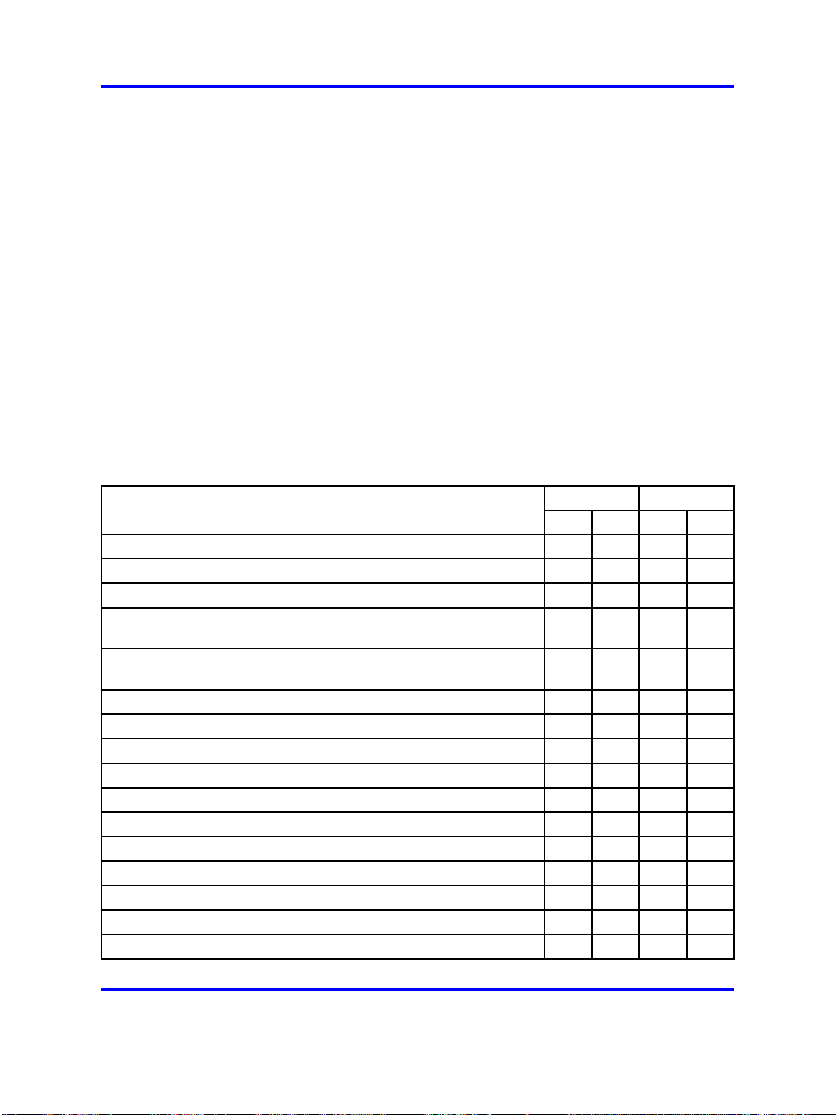
Each of the trunk cards was designed to fit a specific system need. Use
Table 6 "Trunk card characteristics" (page 45) to select the trunk card that
meets system needs.
Table 6
Trunk card characteristics
Trunk cards 45
Part
Number Description
NT8D14 Universal Trunk card
NT8D15 E and M Trunk card
NTCK16 Generic Central Office
Trunk card
* Central office (CO), Foreign Exchange (FX), and Wide Area Telephone Service (WATS)
trunks.
Trun
ks Trunk Types
8
CO/FX/WATS trunks*,
direct inward dial trunks,
TIE trunks,
Loop Dial Repeating trunks
Recorded Announcement
trunks,
Paging trunks
4
2-wire E and M Trunks,
4-wire E and M Trunks,
4-wire DX trunks,
Paging trunks
8
CO trunks IPE
Architect
ure
IPE
IPE
NT8D14 Universal Trunk card
The NT8D14 Universal Trunk card is an intelligent four-channel trunk card
that is designed to be used in a variety of applications. It supports the
following five trunk types:
• Central office (CO), Foreign Exchange (FEX), and Wide Area
Telephone Service (WATS) trunks
• Direct Inward Dial (DID) trunks
• TIE trunks: two-way Loop Dial Repeating (LDR) and two-way loop
Outgoing Automatic Incoming Dial (OAID)
Copyright © 2003-2008 Nortel Networks
.
Nortel Communication Server 1000
Circuit Card Reference
NN43001-311 02.06 Standard
27 August 2008
Page 46

46 Overview
• Recorded Announcement (RAN) trunks
• Paging (PAG) trunks
The universal trunk card also supports Music, Automatic Wake Up, and
Direct Inward System Access (DISA) features.
NT8D15 E and M Trunk card
The NT8D15 E and M Trunk card is an intelligent four-channel trunk card
that is designed to be used when connecting to the following types of
trunks:
• 2-wire E and M Type I signaling trunks
•
4-wire E and M Trunks with:
—
Type I or Type II signaling
— Duplex (DX) signaling
•
Paging (PAG) trunks
The trunk type and function can be configured on a per port basis. Dialing
outpulsing is provided on the card. Make and break ratios are defined in
software and downloaded by software commands.
Installation
NTCK16 Generic Central Office Trunk card
The NTCK16 generic central office trunk cards support up to eight analog
central office trunks. They can be installed in any IPE slot that supports
IPE. The cards are available with or without the Periodic Pulse Metering
(PPM) feature. The cards are also available in numerous countries.
This section provides a high-level description of how to install and test
trunk cards.
IPE trunk cards can be installed in any IPE slot of the NT8D37 IPE
module. Figure 10 "IPE trunk cards installed in an NT8D37 IPE module"
(page 47) shows where an IPE trunk card can be installed in an NT8D37
IPE module.
When installing trunk cards, these general procedures should be used:
Procedure 1
Installing a trunk card
Step Action
1 Configure the jumpers and switches on the trunk card (if any) to
meet the system needs.
Copyright © 2003-2008 Nortel Networks
.
Nortel Communication Server 1000
Circuit Card Reference
NN43001-311 02.06 Standard
27 August 2008
Page 47
2 Install the trunk card into the selected slot.
Figure 10
IPE trunk cards installed in an NT8D37 IPE module
3 Install the cable that connects the backplane connector on the
IPE module to the module I/O panel.
Operation 47
Operation
4 Connect a 25-pair cable from the module I/O panel connector to
the Main Distribution Frame (MDF).
5 Connect the trunk card output to the selected terminal equipment
at the MDF.
6 Configure the individual trunk interface unit using the Trunk
Administration program (LD 14) and the Trunk Route
Administration program (LD 16).
--End--
Once these steps are complete, the trunk card is ready for use.
This section describes how trunk cards fit into the CS 1000E, CS 1000M,
and Meridian 1architecture, the buses that carry signals to and from the
trunk cards, and how they connect to terminal equipment. See Table 7
"Differences between IPE parameters" (page 48) for IPE parameters.
Copyright © 2003-2008 Nortel Networks
.
Nortel Communication Server 1000
Circuit Card Reference
NN43001-311 02.06 Standard
27 August 2008
Page 48

48 Overview
Host interface bus
Cards based on the IPE bus use a built-in microcontroller. The IPE
microcontroller is used for the following:
• to perform local diagnostics (self-test)
• to configure the card according to instructions issued by the system
processor
•
to report back to the system processor information such as card
identification (type, vintage, and serial number), firmware version, and
programmed configuration status.
Table 7
Differences between IPE parameters
Parameter IPE
Card Dimensions 31.75 x 25.4 x 2.2 cm. (12.5 x10.0 x 0.875 in.)
Network Interface DS-30X Loops
Communication Interface card LAN Link
Microcontroller
8031
Peripheral Interface card NT8D01 Controller card
Network Interface card NT8D04 Superloop Network card
Modules NT8D37 IPE module
Intelligent Peripheral Equipment
IPE trunk cards all share a similar architecture. Figure 11 "Typical
IPE trunk card architecture" (page 49) shows a typical IPE trunk card
architecture. The various trunk cards differ only in the number and types of
trunk interface units.
Copyright © 2003-2008 Nortel Networks
.
Nortel Communication Server 1000
Circuit Card Reference
NN43001-311 02.06 Standard
27 August 2008
Page 49

Figure 11
Typical IPE trunk card architecture
Operation 49
The switch communicates with IPE modules over two separate interfaces.
Voice and signaling data are sent and received over DS-30X loops and
maintenance data is sent over a separate asynchronous communication
link called the card LAN link.
Signaling data is information directly related to the operation of the
telephone line. Some examples of signaling commands are as follows:
• off hook/on hook
• ringing signal on/off
• message waiting lamp on/off
Copyright © 2003-2008 Nortel Networks
.
Nortel Communication Server 1000
Circuit Card Reference
NN43001-311 02.06 Standard
27 August 2008
Page 50

50 Overview
Maintenance data is data relating to the configuration and operation of
the IPE card, and is carried on the card LAN link. Some examples of
maintenance data are as follows:
• polling
• reporting of self-test status
• CPU initiated card reset
•
reporting of card ID (card type and hardware vintage)
• reporting of firmware version
• downloading trunk interface unit configuration
• reporting of trunk interface unit configuration
•
enabling/disabling of the DS-30X network loop bus
• reporting of card status
DS-30X loops The interfaces provided by the line and trunk cards
connect to conventional 2-wire (tip and ring) line facilities. IPE analog
line and trunk cards convert the incoming analog voice and signaling
information to digital form, and route it to the Common Equipment (CE)
CPU over DS-30X network loops. Conversely, digital voice and signaling
information from the CPU is sent over DS-30X network loops to the analog
line and trunk cards where it is converted to analog form and applied to the
line or trunk facility.
IPE digital line cards receive the data from the digital phone terminal as
512 kHz Time Compressed Multiplexed (TCM) data. The digital line card
converts that data to a format compatible with the DS-30X loop, and
transmits it in the next available timeslot. When a word is received from
the DS-30X loop, the digital line card converts it to the TCM format and
transmits it to the digital phone terminal over the digital line facility.
A separate dedicated DS-30X network loop is extended between each
IPE line/trunk card and the controller cards within an IPE module (or the
controller circuits on a network/DTR card in a CE module). A DS-30X
network loop is composed of two synchronous serial data buses. One bus
transports in the transmit (Tx) direction toward the line facility and the other
in the receive (Rx) direction toward the common equipment.
Each bus has 32 channels for pulse code modulated (PCM) voice data.
Each channel consists of a 10-bit word. See Figure 12 "DS-30X loop data
format" (page 51).
Copyright © 2003-2008 Nortel Networks
Nortel Communication Server 1000
Circuit Card Reference
NN43001-311 02.06 Standard
27 August 2008
.
Page 51

Eight of the 10 bits are for PCM data, one bit is the call signaling bit,
and the last bit is a data valid bit. The 8-bit PCM portion of a channel is
called a
the 5.12 MHz clock frequency supplied by the controller card). The
timeslot repetition rate for a single channel is 8 kHz. The controller card
also supplies a locally generated 1 kHz frame sync signal for channel
synchronization.
Signaling data is transmitted to and from the line cards using the call
signaling bit within the 10-bit channel. When the line card detects
a condition that the switch needs to know about, it creates a 24-bit
signaling word. This word is shifted out on the signaling bit for the
associated channel one bit at a time during 24 successive DS-30X frames.
Conversely, when the switch sends signaling data to the line card, it is sent
as a 24-bit word divided among 24 successive DS-30X frames.
Figure 12
DS-30X loop data format
Operation 51
timeslot . The DS-30X loop is clocked at 2.56 Mbps (one-half
DS-30Y network loops extend between controller cards and superloop
network cards in the common equipment, and function in a manner similar
to DS-30X loops. See Figure 13 "Network connections to IPE modules"
(page 52).
Essentially, a DS-30Y loop carries the PCM timeslot traffic of a DS-30X
loop. Four DS-30Y network loops form a superloop with a capacity of 128
channels (120 usable timeslots).
See Communication Server 1000M and Meridian 1 Large System Planning
and Engineering (NN43021-220) for more information on superloops.
Copyright © 2003-2008 Nortel Networks
.
Nortel Communication Server 1000
Circuit Card Reference
NN43001-311 02.06 Standard
27 August 2008
Page 52

52 Overview
Card LAN link Maintenance communication is the exchange of control
and status data between IPE line or trunk cards and the CE CPU by way
of the NT8D01 Controller Card. Maintenance data is transported via the
card LAN link. This link is composed of two asynchronous serial buses
(called the Async card LAN link in Figure 11 "Typical IPE trunk card
architecture" (page 49)). The output bus is used by the controller for output
of control data to the trunk card.The input bus is used by the controller for
input of trunk card status data.
Figure 13
Network connections to IPE modules
Copyright © 2003-2008 Nortel Networks
.
Nortel Communication Server 1000
Circuit Card Reference
NN43001-311 02.06 Standard
27 August 2008
Page 53

Operation 53
A card LAN link bus is common to all of the line/trunk card slots within an
IPE module (or IPE section of a CE module). This bus is arranged in a
master/slave configuration where the controller card is the master and all
other cards are slaves. The module backplane provides each line/trunk
card slot with a unique hardwired slot address. This slot address enables
a slave card to respond when addressed by the controller card. The
controller card communicates with only one slave at a time.
In normal operation, the controller card continually scans (polls) all of the
slave cards connected to the card LAN to monitor their presence and
operational status. The slave card sends replies to the controller on the
input bus along with its card slot address for identification. In this reply,
the slave informs the controller if any change in card status has taken
place. The controller can then prompt the slave for specific information.
Slaves only respond when prompted by the controller; they do not initiate
exchange of control or status data on their own.
When an IPE line or trunk card is first plugged into the backplane, it runs
a self-test. When the self test is completed, a properly functioning card
responds to the next controller card poll with the self-test status. The
controller then queries for card identification and other status information.
The controller then downloads all applicable configuration data to the
line/trunk card, initializes it, and puts it into an operational mode.
The network card regularly polls the IPE cards during TS0 to see if any
of them has a message to be sent. When an IPE card has a message
waiting it responds to the poll by sending a series of 1s during the next
five successive timeslot 0s. The network card responds by sending a
"message send enable" message (all 1s). The IPE card replies by sending
1, 1, 1, 0, and then the message in successive timeslot 0s.
Trunk interface unit
Once the 8-bit digital voice signal has been received by the trunk card, it
must be converted back into an analog signal, filtered, and driven onto the
analog trunk line through an impedance matching and balance network.
The trunk interface also includes the logic necessary to place outgoing call
signaling onto the trunk, or the logic to connect to special services such as
recorded announcement and paging equipment.
Figure 14 "Typical trunk interface unit block diagram" (page 54) shows a
typical example of the logic that performs these functions. Each part of the
trunk interface unit is discussed in the following section.
Copyright © 2003-2008 Nortel Networks
.
Nortel Communication Server 1000
Circuit Card Reference
NN43001-311 02.06 Standard
27 August 2008
Page 54
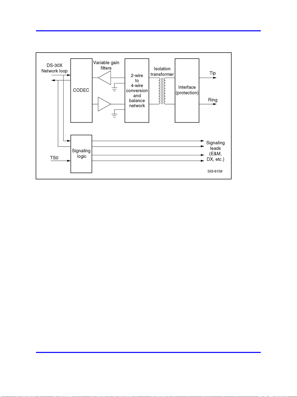
54 Overview
Figure 14
Typical trunk interface unit block diagram
Coder/Decoder circuit The coder/decoder (codec) performs Analog
to Digital (A/D) and Digital to Analog (D/A) conversion of the line analog
voiceband signal to and from a digital PCM signal. This signal can be
coded and decoded using either the A-Law or the µ-Law companding
algorithm. On some trunk cards the decoding algorithm depends of the
type of codec installed when the board is built. On others, it is an option
selected using a software overlay.
Variable gain filters Audio signals received from the analog phone
trunk are passed through a low-pass A/D monolithic filter that limits the
frequency spread of the input signal to a nominal 200–3400 Hz bandwidth.
The audio signal is then applied to the input of the codec. Audio signals
coming from the CODEC are passed through a low-pass A/D monolithic
filter that integrates the amplitude modulated pulses coming from the
CODEC, and then filters and amplifies the result.
On some of the trunk cards, the gain of these filters can be programmed
by the system controller. This allows the system to make up for line losses
according to the loss plan.
Balancing network Depending on the card type, the balancing
network is capable of providing either a 600 ohm or a 900 ohm (or both)
impedance matching network. It also converts the 2-wire transmission path
Copyright © 2003-2008 Nortel Networks
.
Nortel Communication Server 1000
Circuit Card Reference
NN43001-311 02.06 Standard
27 August 2008
Page 55

(tip and ring) to a 4-wire transmission path (Rx/ground and Tx/ground).
The balancing network is a transformer/analog (hybrid) circuit combination.
Signaling circuits Signaling circuits are relays that place outgoing call
signaling onto the trunk. Signal detection circuits monitor the incoming call
signaling.
Control signals Control signals and logic are provided when the trunk is
going to be connected to special services such as recorded announcement
and paging equipment.
Serial Data Interface (SDI) cards
The NT8D41BA QSDI paddle board provides four bidirectional
asynchronous serial ports for the system processor, and the QPC841
QSDI card also provides four. Any device that conforms to the RS-232-C
serial communication standard can be connected to these serial ports.
The electrical interface uses either standard RS-232-C signals or a special
high-speed interface that combines the high-speed differential interface
of the RS-422-A standard with the handshake signals of the RS-232-C
standard.
Serial Data Interface (SDI) cards 55
The RS-232-C interface is normally used when data rates are less
than 19.2 Kbps, and the cable length is less than 15.24 m (50 ft). The
high-speed interface is used when the signal rates are greater than 19.2
kbps (up to 64 kbps) and/or when the cable length is greater than 15.24
m (50 ft).
Table 8 "Serial data interface cards" (page 55) shows compatibility
between the three SDI cards and the various switch options.
Table 8
Serial data interface cards
Card
NT8D41BA
QPC841
Ports Port types
4
4
The NT8D41BA QSDI paddle board does not use a front panel. It mounts
to the rear of the backplane in the NT5D21 Core/Network module, and
does not consume a module slot. The RS-232-C connections are brought
out through special cables to the backplane I/O panel.
Compatible System Options
51C, 61C 81C
RS-232-C asynchronous X X
RS-232-C asynchronous X X
Copyright © 2003-2008 Nortel Networks
.
Nortel Communication Server 1000
Circuit Card Reference
NN43001-311 02.06 Standard
27 August 2008
Page 56

56 Overview
Uses
Features
The QPC841 Quad SDI card mounts in standard backplane slots and
its serial interface connectors are located on the card front panels. A
list of the modules that can be mounted in is given in the section on the
individual card.
Examples of asynchronous devices that can be connected to the system
processor using the NT8D41BA QSDI paddle board and the QPC841
Quad SDI card are:
•
an administration and maintenance terminal
• a background terminal for use in a hotel/motel
• the Automatic Call Distribution (ACD) feature
• the Call Detail Recording (CDR) feature
The NT8D41 QSDI paddle board and the QPC841 QSDI card provide the
following features:
• asynchronous serial data interface ports, each supporting
— RS-232-C interface
—
— Asynchronous, start-stop operation
—
—
—
•
enable/disable switch and LED
•
input/output (I/O) device address selectable by on-board switches.
Specifications
This section lists the specifications shared by all of the SDI cards. See
the appropriate section in this document for information specific to any
particular card.
Power consumption
The SDI cards obtain their power directly from the module backplane.
Power consumption for each of the cards is shown in Table 9 "Power
consumption" (page 57).
8–bit ASCII data with parity and stop bit
Data rates of 150, 300, 600, 1200, 2400, 4800, and 9600 baud
Data terminal equipment (DTE) emulation mode
Data communication equipment (DCE) emulation mode
Copyright © 2003-2008 Nortel Networks
.
Nortel Communication Server 1000
Circuit Card Reference
NN43001-311 02.06 Standard
27 August 2008
Page 57
Table 9
Power consumption
Serial Data Interface (SDI) cards 57
Maximum power consumption
Voltage
+5 VDC ±5% 1.0 Amp 1.5 Amp
+12 VDC ±5% 100 mA 100 mA
–12 VDC ±5% 100 mA 100 mA
NT8D41BA
QPC841
Environmental
The SDI cards operate without degradation under the conditions listed in
Table 10 "Environmental specifications" (page 57).
Table 10
Environmental specifications
Specification Operation Storage
Ambient temperature
Relative humidity
(non-condensing)
Altitude
to 50
to 122
C;
F)
0
(32
5% to 95% 0% to 95%
3500m;
(11000 ft)
–55
(–58
15000m;
(50000 ft)
to +70C;
to 158F)
Electrostatic discharge
The SDI cards meet the requirements of the IEC 801-2, clause 8.0
procedure. They can withstand a direct discharge of ±5 to ±20 kV without
being damaged.
Electromagnetic interference
The CS 1000E, CS 1000M, and Meridian 1systems meet the requirements
of FCC Part 15 and CSA C108.8 electromagnetic interference (EMI)
standards as a class "A" computing device. To accomplish this, the SDI
cables must exit the module through EMI filters on the I/O panel.
Reliability
The Mean Time Between Failure (MTBF) for all SDI cards is 55 years at
40¡C and 29 years at 55¡C.
Installation
To use a serial data interface card in a CS 1000E, CS 1000M, or Meridian
1system, first install the card in the system, and then configure the system
software to recognize it. These steps are discussed in the following
sections.
Copyright © 2003-2008 Nortel Networks
Nortel Communication Server 1000
Circuit Card Reference
NN43001-311 02.06 Standard
27 August 2008
.
Page 58

58 Overview
Maintenance
Instructions for cabling the serial data interface cards to the various system
consoles and peripherals are found in Communication Server 1000M and
Meridian 1 Large System Installation and Configuration (NN43021-310).
Configuring the system software
Once an SDI card has been installed in the system, the system
software needs to be configured to recognize it. This is done using the
Configuration Record program LD 17. Instructions for the Configuration
Record program are found in Software Input/Output Reference —
Administration (NN43001-611).
The following maintenance programs are used to maintain individual SDI
asynchronous ports. The program used depends on the application of the
port.
•
LD 37 Input/Output Diagnostics – Used for system terminal, printer,
background terminal ports, and system monitor status.
•
LD 42 Call Detail Recording (CDR) Diagnostic – For checking CDR
links and CDR system terminals.
The following maintenance program is used to maintain individual SDI
synchronous ports.
•
LD 48 Link Diagnostic – For checking Automatic Call Distribution
(ACD) and Meridian Link ports.
Instructions for running the various maintenance programs are found
in Software Input/Output Reference — Administration (NN43001-611).
System messages are interpreted in Software Input/Output Reference —
System Messages (NN43001-712).
Copyright © 2003-2008 Nortel Networks
.
Nortel Communication Server 1000
Circuit Card Reference
NN43001-311 02.06 Standard
27 August 2008
Page 59

.
Circuit card installation
Contents
This section contains information on the following topics:
“Card slots - Large System” (page 59)
“Circuit and installation” (page 60)
“Precautions” (page 63)
“Installing a circuit card” (page 64)
Card slots - Large System
The following table in this chapter identifies card slot compatibility in the
following modules:
• NT4N41 Core/Network module required for CS 1000M SG, CS 1000M
MG, Meridian 1 PBX 61CCall Processor (CP) PII, CP PIV, and
Meridian 1 PBX 81C
59
•
NT4N46 Core/Network module required for CS 1000M MGand Option
81C CP PII, CP PIV
•
NT6D60 Core/Network module required for the CS 1000M MGand
Option 81C only
•
NT8D35 Network module required for CS 1000M MGand Meridian
1 PBX 81C
• NT8D37 Intelligent Peripheral Equipment (IPE) module required for
CS 1000M HG, CS 1000M SG, CS 1000M MG, Meridian 1 Option 51,
Meridian 1 PBX 61C, and Meridian 1 PBX 81C
Copyright © 2003-2008 Nortel Networks
Nortel Communication Server 1000
Circuit Card Reference
NN43001-311 02.06 Standard
27 August 2008
.
Page 60

60 Circuit card installation
Circuit and installation
Table 11
Large Systemcard slots
Component Large System
A0786611 Call Processor Pentium II®card
81C Core/Net: "CP"
A0810486 Call Processor Pentium II 81C Core/Net: "CP"
NT1P61 Fiber Superloop Network card Core/Net: 0–7
NT1P62 Fiber Peripheral Controller card IPE: "Contr"
NT1R52 Remote Carrier Interface IPE: "Contr"
NT1R20 Off-Premise Station IPE: any slot but "Contr"
NT4D18 Hybrid Bus Terminator Core/Net: between 11 and 12
NT4D19 and NT423 Hybrid Bus Terminator Core/Net: between 0 and 1
NT4D20 and NT422 Hybrid Bus Terminator Core/Net: between 1 and 2
NT4N43 Multi-Medium DIsk Unit 81C Core/Net:
NT4N64 Call Processor Pentium II card 61C Core/Net: CP PII
NT4N64 Call Processor Pentium II card 81C Core/Net: CP PII
NT4N39 Call Processor Pentium IV card 61C Core/Net: CP PIV
NT4N39 Call Processor Pentium IV card 81C Core/Net: CP PIV
NT4N65 cPCI
®
Core to Network Interface card
NT4N66 cPCI Core to Network Interface
81C Core/Net: c9–c12
81C Core/Net cPCI Core backplane: 9–12
Transition card
NT4N67 System Utility card 81C Core/Net: c15
NT4N68 System Utility Transition card 81C Core/Net cPCI Core backplane:
NT5D11 and
IPE: any slot but "Contr"
NT5D14 Line side T1 Line card
NT5D12 Dual DTI/PRI card Core/Net: 0–7
NT5D61 Input/Output Disk Unit with CD-ROM
61C Core/Net: 17, 18 and 19
(MMDU)
NT5K02 Analog Line card IPE: any slot but "Contr"
NT5K07 Universal Trunk card IPE: any slot but "Contr"
NT5K17 Direct Dial Inward Trunk card IPE: any slot but "Contr"
NT5K18 Central Office Trunk card IPE: any slot but "Contr"
NT5K19 E and M Trunk card IPE: any slot but "Contr"
NT5K35 D-channel Handler Interface Core/Net: 0-7
Net: 5-12
NT5K36 Direct Inward/Direct Outward Dial
IPE: any slot but "Contr"
Trunk card
Nortel Communication Server 1000
Circuit Card Reference
NN43001-311 02.06 Standard
Copyright © 2003-2008 Nortel Networks
27 August 2008
.
Page 61

Table 11
Large Systemcard slots (cont’d.)
Component Large System
NT5K70 Central Office Trunk card IPE: any slot but "Contr"
NT5K71 Central Office Trunk card IPE: any slot but "Contr"
NT5K72 E and M Trunk card IPE: any slot but "Contr"
NT5K82 Central Office Trunk card IPE: any slot but "Contr"
NT5K83 E and M Trunk card IPE: any slot but "Contr"
NT5K84 Direct Inward Dial Trunk card IPE: any slot but "Contr"
NT5K90 Central Office Trunk card IPE: any slot but "Contr"
NT5K93 Central Office Trunk card IPE: any slot but "Contr"
NT5K96 Analog Line card IPE: any slot but "Contr"
NT5K99 Central Office Trunk card IPE: any slot but "Contr"
NT5K20 Extended Tone Detector IPE: any slot but "Contr"
NT6D65 Core to Network Interface 61C Core/Net: 12
NT6D66 Call Processor card 61C Core/Net: 15 and 16
Circuit and installation 61
NT6D70
IPE: any slot but "Contr"
S/T Interface Line card
NT6D71
IPE: any slot but "Contr"
U Interface Line card
NT6D72 Basic Rate Signal Concentrator card IPE: any slot but "Contr"
NT6D73
Core/Net: 0–7
Multi-purpose ISDN Signaling Processor card
NT6D80 MSDL Core/Net: 0–7
NT7D16 Data Access card IPE: any slot but "Contr"
NT7R51 Local Carrier Interface Core/Net: 0–7
NT8D01 Controller card IPE: "Contr"
NT8D02 Digital Line card IPE: any slot but "Contr"
NT8D04 Superloop Network card Core/Net: 0–7
Net: 5-12
NT8D09 Analog Message Waiting Line card IPE: any slot but "Contr"
NT8D14 Universal Trunk card IPE: any slot but "Contr"
NT8D15 E and M Trunk card IPE: any slot but "Contr"
NT8D16 Digitone Receiver card IPE: any slot but "Contr"
NT8D17 Conference/TDS card Core/Net: 0–7
NT8D41 Dual Port Serial Data Interface card Serial Port back of Core/Net module
Nortel Communication Server 1000
Circuit Card Reference
NN43001-311 02.06 Standard
Copyright © 2003-2008 Nortel Networks
27 August 2008
.
Page 62

62 Circuit card installation
Table 11
Large Systemcard slots (cont’d.)
Component Large System
NT9D19 Call Processor card 61C Core/Net: 15 and 16
NTAG03 Central Office Trunk card IPE: any slot but "Contr"
NTAG04 Central Office/Direct Inward Dial Trunk
IPE: any slot but "Contr"
card
NTAG36 Nortel Integrated Recorded Announcer IPE: any slot but "Contr"
NTBK51 Downloadable D-channel
Connects to DDP card
daughterboard
NTCK16 Generic Central Office Trunk card IPE: any slot but "Contr"
NTCK43AA Primary Rate Interface card Core/Net: 0-7
Net: 5-11, 13-14
NTRB33 FIber Junctor Interface card For 81C: Core/Net: 8 and 9, Net module: 2 and
3
NTRE39 Optical Cable Management card For 81C: Net module: the slot to the right side
of 14, the slot to the left of the 3PE in slot 1
QPC43 Peripheral Signaling card Core/Net: 10
Net: 4
QPC71 E&M/DX Trunk card IPE: any slot but "Contr"
QPC414 Network card Core/Net: 0–7
Net: 5-12
QPC441 3-Port Extender card Core/Net: 11
Net: 1
QPC471 Clock Controller card 61C Core/Net: 9
Net: 5 -12
For 81C, use NT8D35 Net slot 13; in QSD39
shelf, use Net slot 2; in QSD40 shelf, use slot
13
QPC578 Integrated Services Digital Line card IPE: any slot but "Contr"
QPC659 Dual Loop Peripheral Buffer card IPE: "DLB"
QPC720 Primary Rate Interface card Core/Net: 0–7
Net: 5–11, 13–14
QPC775 Clock Controller 61C Core/Net: slot 14.
For 81C use NT8D35 Net slot 13; in QSD39
shelf, use Net slot 2; in QSD40 shelf, use slot
13.
QPC789 16-Port 500/2500 Message Waiting
IPE: any slot but "Contr"
Line card
QPC841 4-Port Serial Data Interface card Core/Net: 0-7
Nortel Communication Server 1000
Circuit Card Reference
NN43001-311 02.06 Standard
Copyright © 2003-2008 Nortel Networks
27 August 2008
.
Page 63
Precautions
Precautions 63
To avoid personal injury and equipment damage, review the following
guidelines before handling system equipment.
WARNING
Module covers are not hinged; do not let go of the covers. Lift
covers away from the module and set them out of your work
area.
WARNING
Circuit cards may contain a lithium battery. There is a danger of
explosion if the battery is incorrectly replaced. Do not replace
components on any circuit card; you must replace the entire
card.
Dispose of circuit cards according to the manufacturer’s
instructions.
To avoid damage to circuit cards from static discharge, wear a properly
connected antistatic wrist strap when you work on system equipment. If a
wrist strap is not available, regularly touch one of the bare metal strips in
a module to discharge static. Figure 15 "Static discharge points" (page
64) shows the recommended connection points for the wrist strap and the
bare metal strips you should touch.
Handle circuit cards as follows:
• Unpack or handle cards away from electric motors, transformers, or
similar machinery.
• Handle cards by the edges only. Do not touch the contacts or
components.
• Set cards on a protective antistatic bag. If an antistatic bag is not
available, hand-hold the card, or set it in a card cage unseated from
the connectors.
• Store cards in protective packing. Do not stack cards on top of each
other unless they are packaged.
• Keep cards installed in the system as much as possible to avoid dirty
contacts and unnecessary wear.
• Store cards in a cool, dry, dust-free area.
Copyright © 2003-2008 Nortel Networks
.
Nortel Communication Server 1000
Circuit Card Reference
NN43001-311 02.06 Standard
27 August 2008
Page 64
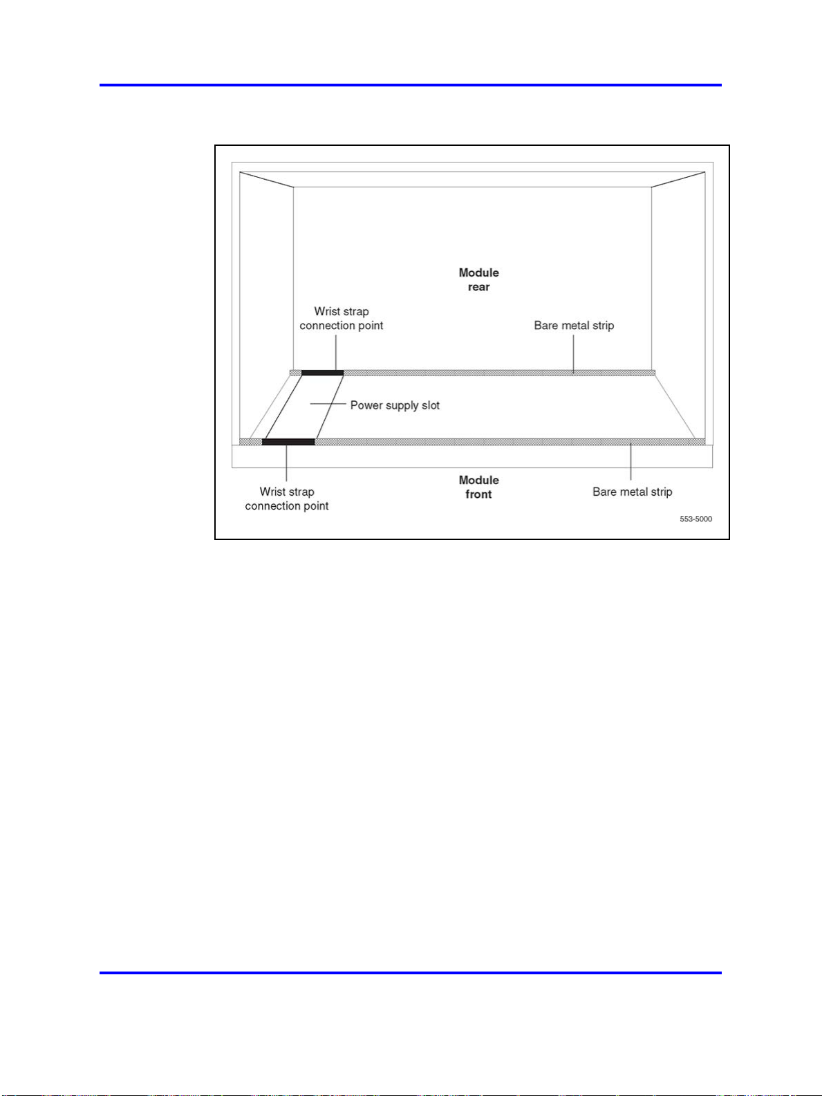
64 Circuit card installation
Figure 15
Static discharge points
During repair and maintenance procedures do the following:
• Turn off the circuit breaker or switch for a module power supply before
the power supply is removed or inserted.
• In AC-powered systems, capacitors in the power supply must
discharge. Wait five full minutes between turning off the circuit breaker
and removing the power supply from the module.
• Software disable cards, if applicable, before they are removed or
inserted.
• Hardware disable cards, whenever there is an enable/disable switch,
before they are removed or inserted.
• Return defective or heavily contaminated cards to a repair center. Do
not try to repair or clean them.
Installing a circuit card
This procedure provides detailed installation instructions for circuit cards.
Copyright © 2003-2008 Nortel Networks
.
Nortel Communication Server 1000
Circuit Card Reference
NN43001-311 02.06 Standard
27 August 2008
Page 65

Installing a circuit card 65
DANGER
To avoid personal injury and equipment damage, read all of the
guidelines in “Circuit and installation” (page 60) before you begin
installation and follow all guidelines throughout the procedure.
Procedure 2
Installing a circuit card
Step Action
1 Open the protective carton and remove the circuit card from the
antistatic bag. Return the antistatic bag to the carton and store it
for future use.
2 Inspect the card components, faceplate, locking devices,
and connectors for damage. If damaged, tag the card with a
description of the problem and package it for return to a repair
center.
3 Refer to the work order to determine the module and slot location
for the card.
4 If there is an enable/disable (Enb/Dis) switch on the faceplate,
set it to Dis.
5 If there are option switches or jumpers on the card, set them
according to the work order (see “Option settings” (page 79)).
CAUTION
System Failure
Incorrectly set switches on common equipment circuit
cards may cause a system failure.
6 Squeeze the ends of the locking devices on the card and pull
the tabs away from the latch posts and faceplate (see Figure 16
"Installing the circuit card in the card cage" (page 66)).
Copyright © 2003-2008 Nortel Networks
.
Nortel Communication Server 1000
Circuit Card Reference
NN43001-311 02.06 Standard
27 August 2008
Page 66
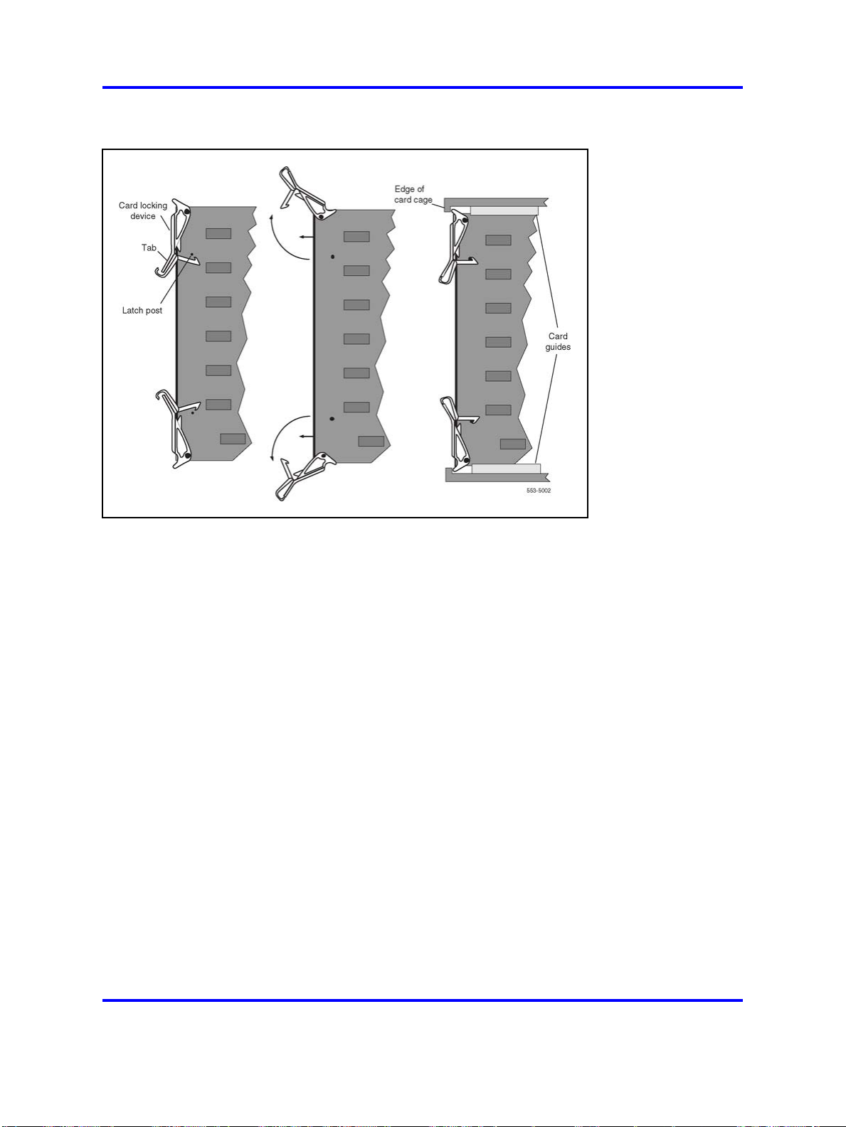
66 Circuit card installation
Figure 16
Installing the circuit card in the card cage
7 Insert the card into the card aligning guides in the card cage.
Gently push the card into the slot until you feel resistance. The
tip of the locking device must be behind the edge of the card
cage (see Figure 16 "Installing the circuit card in the card cage"
(page 66)).
8 Lock the card into position by simultaneously pushing the ends
of the locking devices against the faceplate.
Note: When IPE cards are installed, the red LED on the
faceplate remains lit for two to five seconds as a self-test runs.
If the self-test is completed successfully, the LED flashes
three times and remains lit until the card is configured and
enabled in software, then the LED goes out. If the LED does
not follow the pattern described or operates in any other
manner (such as continually flashing or remaining weakly lit),
replace the card.
9 If there is an enable/disable switch, set it to Enb.
Note: Do not enable the switch on an NT8D04 Superloop
Network card or QPC414 Network card until network loop
cables are installed.
10 If you are adding a voice, conference, or tone and digit loop,
press the manual initialize (Man Int) button on the NT5D03 or the
Copyright © 2003-2008 Nortel Networks
.
Nortel Communication Server 1000
Circuit Card Reference
NN43001-311 02.06 Standard
27 August 2008
Page 67

Installing a circuit card 67
NT5D10 Call Processor if the card is associated with the active
Call Processor:
Note: An initialization causes a momentary interruption in
call processing.
11 If you are installing the card in a working system, refer to the
work order and the technical document, Software Input/Output
Reference — Administration (NN43001-611) to add the required
office data to the system memory.
12 Go to the appropriate test procedure in “Acceptance tests” (page
69).
--End--
Copyright © 2003-2008 Nortel Networks
.
Nortel Communication Server 1000
Circuit Card Reference
NN43001-311 02.06 Standard
27 August 2008
Page 68

68 Circuit card installation
Copyright © 2003-2008 Nortel Networks
.
Nortel Communication Server 1000
Circuit Card Reference
NN43001-311 02.06 Standard
27 August 2008
Page 69

.
Acceptance tests
Contents
This section contains information on the following topics:
“Introduction” (page 69)
“Conference cards” (page 69)
“Digitone receiver cards” (page 72)
“Line cards” (page 72)
“Multifrequency sender cards” (page 73)
“Multifrequency signaling cards” (page 74)
“Network cards” (page 74)
69
“Trunk cards” (page 75)
“Tone and digit switch cards” (page 76)
Introduction
Test procedures for most circuit cards require that internal and external
cabling be installed. See the appropriate installation document for your
system and Telephones and Consoles Fundamentals (NN43001-567) for
cabling procedures.
Conference cards
Procedure 3
Testing conference cards
Step Action
Use this procedure to test a conference card or to test the conference function
of an NT8D17 Conference/TDS card.
1 Log into the system:
Copyright © 2003-2008 Nortel Networks
Nortel Communication Server 1000
Circuit Card Reference
NN43001-311 02.06 Standard
27 August 2008
.
Page 70

70 Acceptance tests
2 Request the status of a loop on the conference card:
3 If the conference card loop is disabled, enable it.
LOGI (password)
LD 38
STAT loop
Conference status is formatted as follows:
CNFC n DSBL n BUSY
"n" represents the number of conference groups disabled and
busy
CHAN n DSBL n BUSY
"n" represents the number of channels disabled and busy
UNEQ
card is not equipped in the system
DSBL card is disabled in software
For an NT8D17 Conference/TDS card, enter:
ENLX loop
(the conference loop is the odd loop of the conference/TDS loop
pair)
Note: The conference/TDS card is not enabled automatically
when it is inserted. You must enable the card with the
command ENLX. (This command is used in LD 34 and LD 46
to address even loops and in LD 38 to address odd loops.)
Enabling the loops with the command ENLL does not enable
the hardware for the card.
For other than an NT8D17 Conference/TDS card, enter:
ENLL loop
(the conference loop must be an even loop for cards other than
the NT8D17)
If the system response is other than OK, seeSoftware
Input/Output Reference — Administration (NN43001-611) to
analyze the messages.
4 Test the conference loop for channel, group, and switching
faults: CNFC loop
If the conference loop passes the tests, the output is OK.
If the system response is other than OK, see Software
Input/Output Reference — Administration (NN43001-611) to
analyze the messages.
5 Prepare the system for a manual conference call on a specified
loop:
CNFC MAN loop c
Where "c" is the manual conference group (1-15)
Copyright © 2003-2008 Nortel Networks
.
Nortel Communication Server 1000
Circuit Card Reference
NN43001-311 02.06 Standard
27 August 2008
Page 71

Conference cards 71
A manual conference test is performed by stepping through
conference channels and groups, listening for noise that
indicates a faulty card.
The manual conference test can be performed through a
system terminal or BCS maintenance telephone. If commands
are entered from a maintenance telephone, this telephone
automatically becomes part of the manual conference call.
Only one manual conference call is allowed at one time. A
manual conference consists of only two telephones, where one
telephone acts as a signal source while the other acts as a
listening monitor.
After you enter the CNFC command, any two telephones (one
may already be the maintenance telephone) dialing the special
service prefix code (SPRE) and the digits 93 enters the manual
conference call. The prime directory number (PDN) indicator, if
equipped, lights on each telephone.
Going on-hook takes the telephone out of the manual conference
call, and the test must be restarted.
See LD 38 in
Software Input/Output Reference — Administration
(NN43001-611)
for more detailed information on using this command.
6 Test various channels and conference groups audibly with the
command
CNFC STEP
When stepping through channels and groups, a clicking followed
by silence is normal. Any distortion or other noises indicates a
faulty card.
Once the CNFC STEP command has been entered, entering
C on the system terminal or maintenance telephone steps
through the conference channels. Entering G steps through the
conference groups. There are 15 channels per group and 15
groups per conference card.
Entering an asterisk (*) and END stops the test.
Again, see "LD 38" in the Software Input/Output Reference —
Maintenance (NN43001-711) for detailed information on using
this command.
7 End the session in LD 38:
****
--End--
Copyright © 2003-2008 Nortel Networks
.
Nortel Communication Server 1000
Circuit Card Reference
NN43001-311 02.06 Standard
27 August 2008
Page 72

72 Acceptance tests
Digitone receiver cards
Note: The DTR daughterboard connected to a QPC659 Dual Loop
Peripheral Buffer card cannot be assigned when the IPE shelf is used
in single loop mode.
Procedure 4
Testing digitone receiver cards
Step Action
Use this procedure to test a Digitone receiver (DTR) card, a DTR daughterboard,
or the DTR function on the NT8D18 Network/DTR card.
1 Log into the system:
LOGI (password)
2 See if the Digitone receiver to be tested is disabled: LD 34
STAT
The system responds with the terminal number (TN), or
numbers, of any disabled Digitone receivers.
3 If the Digitone receiver is disabled, enable it:
ENLR l s c uloop, shelf, card, and unit numbers
Line cards
4 Test the Digitone receiver:
DTRlsculoop, shelf, card, and unit numbers
If the system response is other than OK, seeSoftware
Input/Output Reference — Administration (NN43001-611) to
analyze the messages.
5 End the session in LD 34:
****
--End--
Procedure 5
Testing line cards
Step Action
Use this procedure to test a line card.
1 Log into the system:
LOGI (password)
2 Perform a network memory test, continuity test, and signaling
test on a specific loop and shelf:
LD 30
SHLF l sloop and shelf numbers
Copyright © 2003-2008 Nortel Networks
.
Nortel Communication Server 1000
Circuit Card Reference
NN43001-311 02.06 Standard
27 August 2008
Page 73

If the system response is other than OK, see Software
Input/Output Reference — Administration (NN43001-611) to
analyze the messages.
3 For a line card on a superloop, perform a signaling test on a
specific card or unit:
UNTT l s c loop, shelf, and card numbers
For the NT8D02 Digital Line card, enter:
UNTT l s c u loop, shelf, card, and unit numbers
If the system response is other than OK, see Software
Input/Output Reference — Administration (NN43001-611) to
analyze the messages.
4 End the session in LD 30:
****
Multifrequency sender cards
Procedure 6
Testing multifrequency sender cards
Multifrequency sender cards 73
--End--
Step Action
Use this procedure to test a multifrequency sender (MFS) card or the MFS
function of an NT8D17 Conference/TDS card.
1 Log into the system:
LOGI (password)
2 Test and enable an MFS loop:
LD 46
MFS loop
(on the NT8D17 Conference/TDS card, the TDS/MFS loop is the
even loop of the conference/TDS loop pair)
Note: The conference/TDS card is not enabled automatically
when it is inserted. You must enable the card with the
command ENLX. (This command is used in LD 34 and LD 46
to address even loops and in LD 38 to address odd loops.)
Enabling the loops with the command ENLL does not enable
the hardware for the card.
If the system response is other than OK, see Software
Input/Output Reference — Administration (NN43001-611) to
analyze the messages.
3 Access the system from a maintenance telephone; then enter:
LD 46
Give the system approximately 20 seconds to load the program.
Copyright © 2003-2008 Nortel Networks
.
Nortel Communication Server 1000
Circuit Card Reference
NN43001-311 02.06 Standard
27 August 2008
Page 74

74 Acceptance tests
See "Communicating with the Meridian 1" in Software
Input/Output Reference — Administration (NN43001-611) for
details on accessing the system from a maintenance telephone.
4 Obtain 10-second bursts of digits 1 to 9, 0, and 11 to 15 (in that
order) for all digits on the specified loop: TONE loop ALL
Each burst should sound different. If the bursts do not sound
different, replace the card.
5 End the session in LD 46:
****
Multifrequency signaling cards
Procedure 7
Testing multifrequency signaling cards
Step Action
Use this procedure to test a multifrequency signaling card.
1 Log into the system:
LOGI (password)
--End--
2 Test and enable the specified unit:
3 End the session in LD 54:
Network cards
Procedure 8
Testing network cards
Step Action
Use this procedure to test a network card.
1 Log into the system:
2 Perform a network memory test, continuity test, and signaling
LD 54
ATST l s c u loop, shelf, card, and unit numbers
If the system response is other than OK, see Software
Input/Output Reference — Administration (NN43001-611) to
analyze the messages.
****
--End--
LOGI (password)
test: LD 30
LOOP loop can be a specific loop number or ALL
Copyright © 2003-2008 Nortel Networks
.
Nortel Communication Server 1000
Circuit Card Reference
NN43001-311 02.06 Standard
27 August 2008
Page 75

Trunk cards 75
If ALL is specified, all enabled loops (except attendant console
loops) and all shelves on each loop are tested.
If only one loop is being tested and it is disabled, enter ENLL
loop to enable and test a network card associated with the
specified loop. (This command cannot enable network cards
disabled by LD 32.)
Trunk cards
If the system response is other than
OK, see Software
Input/Output Reference — Administration (NN43001-611) to
analyze the messages.
3 End the session in LD 30:
****
--End--
Use the following procedures to test a trunk card.
Procedure 9
Testing a trunk card using a maintenance telephone
Step Action
1 Access the system from a maintenance telephone.
See "Communicating with the Meridian 1" in the Software
Input/Output Reference — Administration (NN43001-611) for
details on accessing the system from a maintenance telephone.
2 Test the trunk unit:
LD 36
TRKlsculoop, shelf, card, and unit numbers
3 If the maintenance telephone is hooked up to a monitor and the
system response is other than OK, see Software Input/Output
Reference — Administration (NN43001-611) to analyze the
messages.
Procedure 10
Testing a trunk card using a system terminal
Step Action
1 Log into the system:
LOGI (password)
2 Enter:
LD 36
Copyright © 2003-2008 Nortel Networks
--End--
Nortel Communication Server 1000
Circuit Card Reference
NN43001-311 02.06 Standard
27 August 2008
.
Page 76

76 Acceptance tests
3 To test a trunk from a remote test center, seize a central office
(CO) monitor trunk:
CALL
or
CALL l s c u
Seize the automatic number identification (ANI) trunk: TRK l s c
u loop, shelf, card, and unit numbers
When you see the DN? prompt, enter the directory number (DN)
you want the system to dial.
If the system response is other than OK, see the
Input/Output Reference — Administration (NN43001-611) to
analyze the messages.
4 End the session in LD 36:
****
5 Test an automatically identified outward dialing (AIOD) trunk
card:
LD 41
AIOD l s c loop, shelf, and card numbers
If the system response is other than OK, see Software
Input/Output Reference — Administration (NN43001-611) to
analyze the messages.
6 End the session in LD 41:
****
Tone and digit switch cards
Procedure 11
Testing tone and digit switch cards
Software
--End--
Step Action
Use this procedure to test a tone and digit switch (TDS) card or to test the TDS
function of an NT8D17 Conference/TDS card.
1 Log into the system:
LOGI (password)
2 Obtain a list of terminal numbers (TNs) for disabled TDS cards:
LD 34
STAD
3 If the TDS loop to be tested is disabled, enable it.
For an NT8D17 Conference/TDS card, enter:
ENLX loop
Copyright © 2003-2008 Nortel Networks
.
Nortel Communication Server 1000
Circuit Card Reference
NN43001-311 02.06 Standard
27 August 2008
Page 77

Tone and digit switch cards 77
(the TDS/MFS loop is the even loop of the conference/TDS loop
pair)
Note: The conference/TDS card is not enabled automatically
when it is inserted. You must enable the card with the
command ENLX. (This command is used in LD 34 and LD 46
to address even loops and in LD 38 to address odd loops.)
Enabling the loops with the command ENLL does not enable
the hardware for the card.
For other than an NT8D17 Conference/TDS card, enter: ENLL
loop
4 Test the TDS loop:
TDS loop
If the system response is other than OK, see Software
Input/Output Reference — Administration (NN43001-611) to
analyze the messages.
5 End the session in LD 34:
****
6 Using a maintenance telephone, log into the system.
See "Communicating with the Meridian 1" in the Software
Input/Output Reference — Administration (NN43001-611) for
details on accessing the system using a maintenance telephone.
7 From the maintenance telephone, enter:
LD#34##
To test outpulsers and channels for the TDS loop, see Table
12 "TDS tone tests" (page 77) for a sample of the input
commands used with the maintenance telephone. See Software
Input/Output Reference — Administration (NN43001-611) for all
tones that can be tested.
8 Exit LD 34 from the maintenance telephone:
****
--End--
Table 12
TDS tone tests
Dial pad
Input command
BSY#loop## 279#loop## Provides busy tone from TDS loop specified.
C##
equivalent Description
2##
Removes any active tone.
DIA#loop## 342#loop## Provides dial tone from TDS loop specified.
OVF#loop## 683#loop## Provides overflow tone from TDS loop specified.
Nortel Communication Server 1000
Circuit Card Reference
NN43001-311 02.06 Standard
Copyright © 2003-2008 Nortel Networks
27 August 2008
.
Page 78

78 Acceptance tests
Table 12
TDS tone tests (cont’d.)
Dial pad
Input command
equivalent Description
RBK#loop## 725#loop## Provides ringback tone from TDS loop specified.
RNG#loop## 764#loop## Provides ring tone from TDS loop specified.
**** Exits TDS test program.
Copyright © 2003-2008 Nortel Networks
.
Nortel Communication Server 1000
Circuit Card Reference
NN43001-311 02.06 Standard
27 August 2008
Page 79

.
Option settings
Contents
This section contains information on the following topics:
“Circuit card grid” (page 80)
“NT1R20 Off-Premise Station card” (page 81)
Table 14 "General purpose switch settings" (page 83)
“NT6D42 Ringing Generator DC” (page 87)
“NT6D80 Multi-purpose Serial Data Link card” (page 89)
“NT8D14 Universal Trunk card” (page 90)
“NT8D15 E and M Trunk card” (page 92)
79
“NT8D17 Conference/TDS card” (page 93)
“NT8D21 Ringing Generator AC” (page 94)
“NT8D22 System Monitor” (page 94)
“NT8D41BA Quad Serial Data Interface Paddle Board” (page 99)
“QPC43 Peripheral Signaling card” (page 101)
“QPC414 Network card” (page 101)
“QPC441 3-Port Extender cards” (page 101)
“QPC841 4-Port Serial Data Interface card” (page 104)
Copyright © 2003-2008 Nortel Networks
Nortel Communication Server 1000
Circuit Card Reference
NN43001-311 02.06 Standard
27 August 2008
.
Page 80

80 Option settings
Circuit card grid
Some circuit cards contain option switches or jumpers, or both, that define
specific functions. A switch or jumper can be identified by an alphanumeric
coordinate (such as D29) that indicates a location on the card, or by a
switch number (such as SW2) printed on the circuit board (see Figure 17
"Circuit card grid" (page 81)). Positions on a switch (for example, positions
1, 2, 3, and 4 on SW2) are labeled on the switch block.
On a circuit card:
• ON may be indicated by the word "on," the word "up," the word
• OFF may be indicated by the word "down," the word "open," the
Throughout this document, if neither ON nor OFF is given (there is a blank
space) for a position on a switch, that position may be set to either ON or
OFF because it has no function for the option described.
"closed," the number "1," an arrow pointing up, or a solid dot (•).
number "0," or an arrow pointing down.
Copyright © 2003-2008 Nortel Networks
.
Nortel Communication Server 1000
Circuit Card Reference
NN43001-311 02.06 Standard
27 August 2008
Page 81
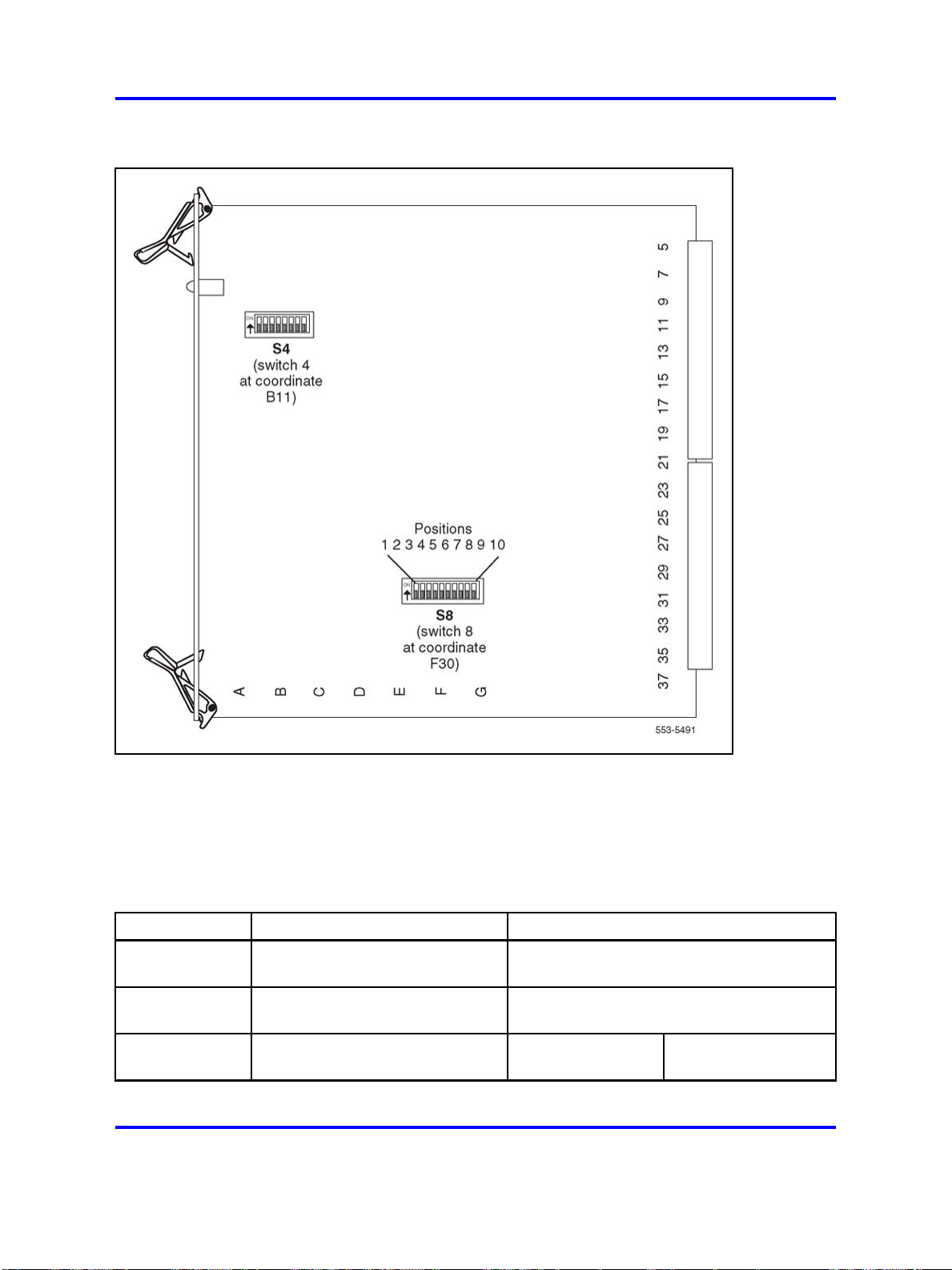
Figure 17
Circuit card grid
NT1R20 Off-Premise Station card 81
NT1R20 Off-Premise Station card
Table 13 "OPS analog line card configuration" (page 81) lists option
settings for the NT1R20 Off-Premise Station analog card.
Table 13
OPS analog line card configuration
Application
Class of Service
(CLS) (Note 1)
Loop resistance
(ohms)
Jumper strap
setting (Note 6)
Copyright © 2003-2008 Nortel Networks
On-premise station (ONS) Off-premise station (OPS)
ONP OPX
0–460
Both JX.0 and JX.1
off
Nortel Communication Server 1000
Circuit Card Reference
NN43001-311 02.06 Standard
27 August 2008
0–2300 (Note 2)
Both JX.0 and JX.1
off
Both JX.0 and JX.1
on
.
Page 82

82 Option settings
Table 13
OPS analog line card configuration (cont’d.)
Application
Class of Service
(CLS) (Note 1)
Loop loss (dB)
(Note 3)
TIMP
(Notes 1, 4)
Class of Service
(CLS) (Note 1)
BIMP
(Notes 1, 4)
Gain treatment
(Note 5)
Note 1: Configured in the Analog (500/2500-type) Telephone Administration program (LD 10).
Note 2: The maximum signaling range supported by the OPS analog line card is 2300 ohms.
Note 3: Loss of untreated (no gain devices) metallic line facility. Upper loss limits correspond to
loop resistance ranges for 26 AWG wire.
Note 4: Default software impedance settings are:
TIMP:
BIMP:
On-premise station (ONS) Off-premise station (OPS)
ONP OPX
0–1.5 >1.5–2.5 >2.5–3.0 0–1.5 >1.5–2.5 >2.5–4.5 >4.5–15
600
ohms
600
ohms
NP CLS
O
600 ohms
600 ohms
600
ohms
ONP OPX
3COM1 3COM2
PX CLS
O
600 ohms
3COM2
600
ohms
600
ohms
600
ohms
No Yes
600
ohms
3COM1 3COM2 3COM2
600
ohms
600
ohms
Note 1: Gain treatment, such as avoicefrequencyrepeater (VFR) is required to limit the actual OPS
loop loss to 4.5 dB, maximum. VFR treatment of metallic loops having untreated loss greater than 15
dB (equivalent to a maximum signaling range of 2300 ohms on 26 AWG wire) is not recommended.
Note 2: Jumper strap settings JX.0 and JX.1 apply to all eight units; "X" indicates the unit number,
0–7. "Off" indicates that a jumper strap is not installed across both pins on a jumper block. Store
unused straps on the OPS analog line card by installing them on a single jumper pin as shown below:
NT5D12 Dual DTI/PRI (DDP) card
Switch setting tables for this card are listed in subsections according to
their function. Bold font designates factory (default) settings.
Nortel Communication Server 1000
Circuit Card Reference
NN43001-311 02.06 Standard
Copyright © 2003-2008 Nortel Networks
27 August 2008
.
Page 83
General purpose switches
Use switch set SW9 for Trunk 0; use switch set SW15 for Trunk 1 (see
Table 14 "General purpose switch settings" (page 83)).
Table 14
General purpose switch settings
Switch Description
1
Framing Mode
NT5D12 Dual DTI/PRI (DDP) card 83
SW9/SW15
switch setting
off - ESF
on - SF
2
3
4
Yellow Alarm Method
Zero Code Suppression Mode
Unused off
Trunk interface switches
A switch provides selection of T1 transmission. Use switch SW4 for
Trunk 0; use switch SW10 for Trunk 1 (see Table 15 "Trunk interface
transmission mode switch settings" (page 83)).
Table 15
Trunk interface transmission mode switch settings
Description
For future use off
T1
A set of three switches provides selection of dB values. Use SW5, SW6,
and SW7 for Trunk 0; use SW11, SW12, and SW13 for Trunk 1 (see Table
16 "Trunk interface line build out switch settings" (page 83)).
off - FDL
on - Digit2
off - B8ZS
on - AMI
SW4/SW10 switch setting
on
Table 16
Trunk interface line build out switch settings
Description
0 dB off off off
7.5 dB
15 dB
Copyright © 2003-2008 Nortel Networks
.
Switch Setting
SW5/SW11 SW6/SW12 SW7/SW13
on on
on
Nortel Communication Server 1000
Circuit Card Reference
NN43001-311 02.06 Standard
27 August 2008
off
off
on
Page 84

84 Option settings
A set of four DIP switches provides selection among three values for
receiver impedance. Use SW8 for Trunk 0; use SW14 for Trunk 1 (see
Table 17 "Trunk interface impedance switch settings" (page 84)).
Table 17
Trunk interface impedance switch settings
Description
75
100
120
Ring ground switches
A set of four DIP switches selects which Ring lines are connected to
ground (see Table 18 "Ring ground switch settings" (page 84)).
Table 18
Ring ground switch settings
Switch
1
2
3
Description
Trunk 0 Transmit
Trunk 0 Receive
Trunk 1 Transmit
SW8/SW14 Switch Settings
off off
on
off off off
off off
S2 switch setting
off - Ring line is not grounded
on- Ring line is grounded
off - Ring line is not grounded
on - Ring line is grounded
off - Ring line is not grounded
on - Ring line is grounded
on
off
on
on
4
DCH mode and address select switches
One switch selects an on-board NTBK51AA D-Channel daughterboard
and an external MSDL/DCHI card. Four other switches provide the
daughterboard address (see Table 19 "DCH mode and address select
switch settings" (page 84)).
Table 19
DCH mode and address select switch settings
Swit
1-4
Copyright © 2003-2008 Nortel Networks
Description
ch
D-Channel daughterboard
Address
off - Ring line is not grounded
Trunk 1 Receive
on - Ring line is grounded
S3 Switch Setting
See the next table.
Nortel Communication Server 1000
Circuit Card Reference
NN43001-311 02.06 Standard
27 August 2008
.
Page 85

Table 19
DCH mode and address select switch settings (cont’d.)
NT5D12 Dual DTI/PRI (DDP) card 85
Swit
5-7
Description
ch
For future use off
8
External DCH or Onboard DDCH
Table 20
NTBK51AA daughterboard address select switch settings
Device Address
2
0
1
2
3
4
5on
6
1
Switch Setting
off off off off
on
off
off off off
on
on on
off off
off
off
on on
7 ononon
8
9
off off off
on
off off
S3 Switch Setting
off - MSDL or DCHI card
on - Onboard DDCH
daughterboard
off off
off off
on
on
off
off
off
off
on
on
10
11
12
13
14
15
off
on on
off off
on
off
on
off
off
on on
off
on on
on on on
on on on on
on
on
Note 1: The maximum number of DCHI, MSDL, and DDCH devices in the system is 16.The
Device Addresses are equivalent to the MSDL DNUM designations. For programming information
on the MSDL, refer to technical document Software Input/Output Reference — Administration
(NN43001-611)guide.
Note 2: Device address 0 is commonly assigned to the System Monitor.
Illustrations of switch locations and settings
Figure 18 "Switch functions and areas" (page 86) displays functional areas
for switches on the NT5D12 DDP card.
Nortel Communication Server 1000
Circuit Card Reference
NN43001-311 02.06 Standard
Copyright © 2003-2008 Nortel Networks
27 August 2008
.
Page 86
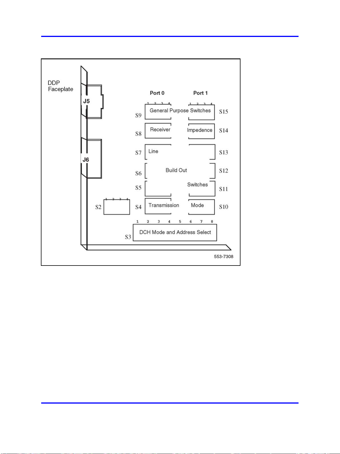
86 Option settings
Figure 18
Switch functions and areas
Figure 19 "Switch default settings" (page 87) displays default settings for
switches on the NT5D12 DDP card.
Copyright © 2003-2008 Nortel Networks
Nortel Communication Server 1000
Circuit Card Reference
NN43001-311 02.06 Standard
27 August 2008
.
Page 87

Figure 19
Switch default settings
NT6D42 Ringing Generator DC 87
NT6D42 Ringing Generator DC
Table 21 "NT6D42 recommended options for North American and British
Telecom" (page 87) through Table 26 "NT6D42CC SW2" (page 89) list
option settings for the NT6D42 Ringing Generator.
Table 21
NT6D42 recommended options for North American and British Telecom
Ringing
Application
North America 20 Hz 86 V ac
Copyright © 2003-2008 Nortel Networks
frequency
.
Ringing
voltage Jumper locations Ringing output
P5
High voltage
Nortel Communication Server 1000
Circuit Card Reference
NN43001-311 02.06 Standard
27 August 2008
Low impedance
Page 88

88 Option settings
Application
Ringing
frequency
Ringing
voltage Jumper locations Ringing output
British Telecom 25 Hz 80 V ac
Table 22
NT6D42 jumper locations P4 and P5
High voltage message waiting Pin location
Disable Jumper in P4
Enable Jumper in P5
Note: One jumper must be installed.
Table 23
NT6D42 jumper location J7
Ringing output Jumper location J7
Low impedance (normal) Connect pins 1 and 2
message waiting
P4
No high voltage
message waiting
Low impedance
High impedance (Australia) Connect pins 2 and 3
Table 24
NT6D42 SW1
Ringing frequency (Hz)
Table 25
NT6D42CB SW2
Ringing
voltage
86 V ac –120 V dc off off off off
86 V ac –150 V dc off off off
80 V ac –120 V dc
80 V ac –150 V dc
75 V ac –120 V dc off
75 V ac –150 V dc off
Position SW1
20 1
25 2
50 3
SW2
Message waiting
voltage 1 2 3 4
on
on
off off off
off off
on
on
on
on
off off
off
on
Copyright © 2003-2008 Nortel Networks
.
Nortel Communication Server 1000
Circuit Card Reference
NN43001-311 02.06 Standard
27 August 2008
Page 89

Table 25
NT6D42CB SW2 (cont’d.)
NT6D80 Multi-purpose Serial Data Link card 89
SW2
Ringing
voltage
70 V ac –120 V dc off off
70 V ac –150 V dc off off
Table 26
NT6D42CC SW2
Ringing
voltage
86 V ac –100 V dc off off off off
86 V ac –150 V dc off off off
80 V ac –100 V dc
80 V ac –150 V dc
75 V ac –100 V dc off
75 V ac –150 V dc off
70 V ac –100 V dc off off
70 V ac –150 V dc off off
Message waiting
voltage 1 2 3 4
on
on on
SW2
Message waiting
voltage 1 2 3 4
on
on
off off off
off off
on
on
off off
off
on
on on
off
on
on
on
off
NT6D80 Multi-purpose Serial Data Link card
Table 27
NT6D80 Multi-purpose Serial Data Link card
Port 0—SW4 Port 0—SW8
RS-232-D DTE or DCE*
RS-422-A DTE (terminal)
RS-422-A DCE (modem)
RS-232-D DTE or DCE*
RS-422-A DTE
RS-422-A DCE
RS-232-D DTE or DCE*
RS-422-A DTE
RS-422-A DCE
Nortel Communication Server 1000
Circuit Card Reference
NN43001-311 02.06 Standard
27 August 2008
Copyright © 2003-2008 Nortel Networks
all off
all off
all on
Port 1—SW3 Port 1—SW7
all off
all off
all on
Port 2—SW2 Port 2—SW6
all off
all off
all on
Port 3—SW1 Port 3—SW5
all off
all on
all off
all off
all on
all off
all off
all on
all off
.
Page 90
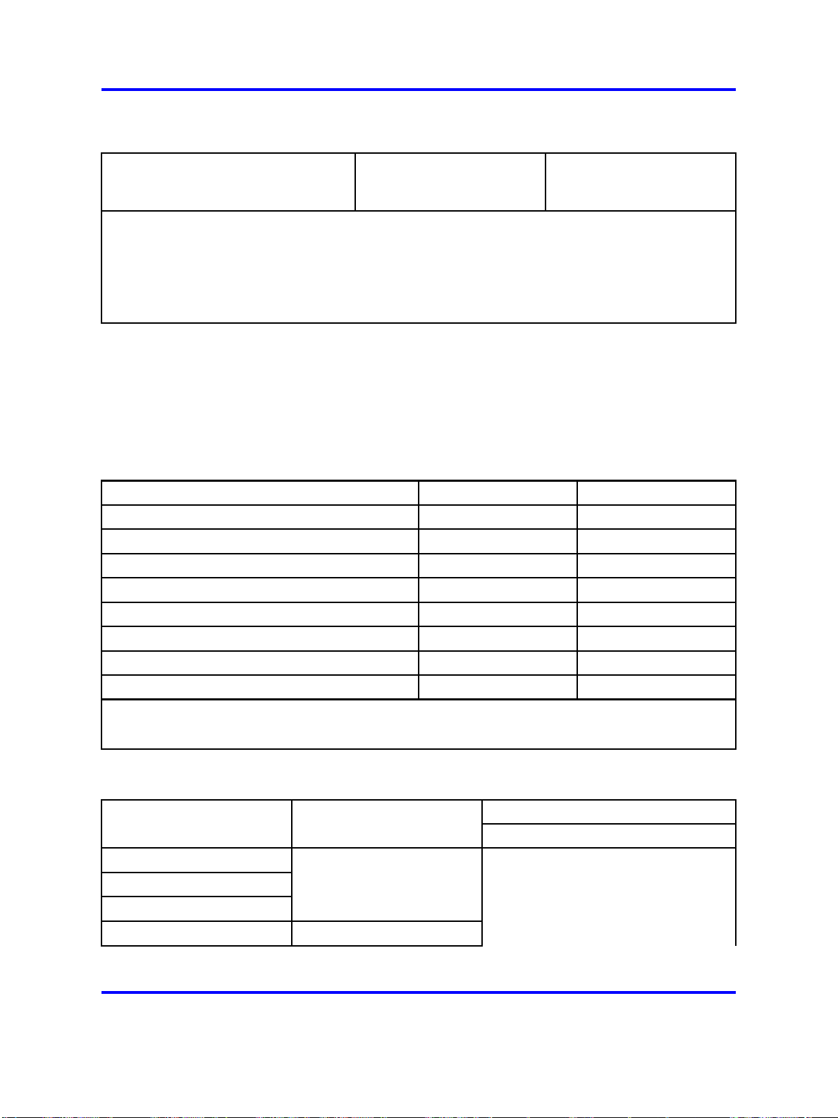
90 Option settings
Table 27
NT6D80 Multi-purpose Serial Data Link card (cont’d.)
RS-232-D DTE or DCE*
RS-422-A DTE
RS-422-A DCE
all off
all off
all on
all off
all on
all off
* RS-232-D DTE and DCE modes are software configured. RS-422-A DTE and DEC modes are
switch configured.
Note: The device number for the MSDL card is configured in LD17 at the prompt DNUM. You must
also set the device number, using switches S9 and S10, on the MSDL card. S9 designates ones
and S10 designates tens. To set the device number as 14, for example, set S10 to 1 and S9 to 4.
NT8D14 Universal Trunk card
Table 28 "NT8D14 vintage AA jumper strap settings" (page 90) through
Table 32 "NT8D14 vintages BA/BB cable loop resistance and loss" (page
92) list option settings for the NT8D14 Universal Trunk card.
Table 28
NT8D14 vintage AA jumper strap settings
Modes Location Jumper strap
Central Office (CO) J1, J2 off
2-way tie trunk (loop dial repeat) J1, J2 off
2-way tie trunk (outgoing/incoming dial) J1, J2 off
Recorded announcement (RAN) J1, J2 off
Paging trunk J1, J2 off
Japan CO/DID operation J1, J2 off
DID operation: loop length > = 20003/4 J1, J2
DID operation: loop length < 2000
3
/4 J1, J2 off
on
Note 1: off = no strap present.
Note 2: Locations (J1, J2) apply to all eight units.
Table 29
NT8D14 vintages BA/BB jumper strap settings-factory standard
Jumper strap settings
Trunk types Loop length J1.X J2.X J3.X J4.X
CO/FX/WATS
Zero–1524 m (5000 ft)
Off Off
1–2 1–2
2-way tie (LDR)
2-way tie (OAID)
DID Zero–600 ohms
Copyright © 2003-2008 Nortel Networks
.
Nortel Communication Server 1000
Circuit Card Reference
NN43001-311 02.06 Standard
27 August 2008
Page 91

NT8D14 Universal Trunk card 91
Jumper strap settings
Trunk types Loop length J1.X J2.X J3.X J4.X
RAN: continuous
operation mode
Paging
Not applicable: RAN and
paging trunks should not
leave the building.
Note: Jumper strap settings J1.X, J2.X, J3.X, and J4.X apply to all eight units; "X" indicates the
unit number, 0–7. "Off" indicates that no jumper strap is installed on a jumper block. Store unused
straps on the universal trunk card by installing them on a single jumper pin as shown below:
Table 30
NT8D14 vintages BA/BB jumper strap settings-extended range
Jumper strap settings
Trunk types Loop length J1.X J2.X J3.X J4.X
CO/FX/WATS
> 1524 m (5000 ft) Off Off
1–2 2–3
2-way tie (LDR)
2-way tie (OAID)
DID > 600 ohms On On
RAN: pulse start or level
start modes
Not applicable: RAN
trunks should not leave
Off Off
1–2 2–3
2–3 1–2
the building.
Note: Jumper strap settings J1.X, J2.X, J3.X, and J4.X apply to all eight units; "X" indicates the unit
number, 0–7. "Off" indicates that no jumper strap is installed on a jumper block.
Table 31
NT8D14 vintages BA/BB trunk types-termination impedance and balance network
Balance network for loop lengths (Note 2)
Zero–915 m
(zero–3000 ft)
915–1524 m
(3000–5000 ft)
> 1524 m
(> 5000 ft)
Trunk types
Terminating
impedance
(Note 1)
CO/FX/WATS 600 or 900 ohms 600 ohms 3COM1 3COM2
2-way tie (LDR) 600 or 900 ohms 600 ohms 3COM1 3COM2
2-way tie (OAID) 600 or 900 ohms 600 ohms 3COM1 3COM2
DID (loop < 600
600 or 900 ohms 600 ohms 3COM1 3COM2
ohms)
Copyright © 2003-2008 Nortel Networks
.
Nortel Communication Server 1000
Circuit Card Reference
NN43001-311 02.06 Standard
27 August 2008
Page 92
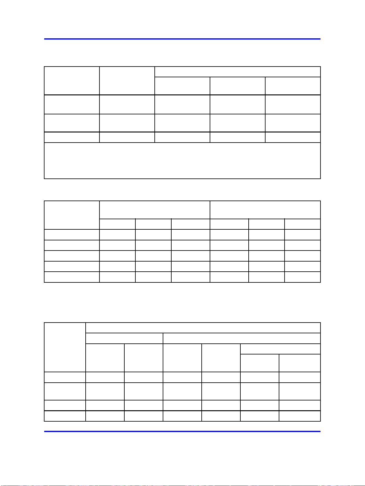
92 Option settings
Table 31
NT8D14 vintages BA/BB trunk types-termination impedance and balance network (cont’d.)
Terminating
impedance
Trunk types
DID (loopˇS 600
ohms)
RAN: continuous
operation mode
Paging 600 ohms 600 ohms N/A N/A
Note 1: The terminating impedance of each trunk unit is software selectable in LD 14 and should
match the nominal impedance of the connecting equipment.
Note 2: The balance network of each trunk unit is software selectable between resistive 600 or 900
ohms or 3COM and is jumper selectable between 3COM1 and 3COM2.
Table 32
NT8D14 vintages BA/BB cable loop resistance and loss
Cable length 22 AWG 24 AWG 26 AWG 22 AWG 24 AWG 26 AWG
915 m (3000 ft)
1524 m (5000 ft)
(Note 1)
600 or 900 ohms 600 ohms N/A 3COM2
600 or 900 ohms 600 or 900 ohms N/A N/A
Cable loop resistance (ohms)
97 155 251 0.9 1.2 1.5
162 260 417 1.6 2.0 2.5
Balance network for loop lengths (Note 2)
Zero–915 m
(zero–3000 ft)
915–1524 m
(3000–5000 ft)
Cable loop loss (dB)
(non-loaded at 1kHz)
> 1524 m
(> 5000 ft)
2225 m (7300 ft)
3566 m (11700 ft)
5639 m (18500 ft)
236 378 609 2.3 3.0 3.7
379 607 977 3.7 4.8 6.0
600 960 1544 5.9 7.6 9.4
NT8D15 E and M Trunk card
Table 33
NT8D15 E and M Trunk card
Mode of operation (Note 2)
2-wire trunk 4-wire trunk
DX tip & ring pair
Jumper
(Note 1) Type I Paging Type I Type II
J1.X off off off off Pins 1–2 Pins 2–3
J2.X
J3.X off off off off (Note 4) (Note 4)
J4.X off off off off Pins 2–3 Pins 1–2
on on
(Note 3)
on on
M—rcv
M—xmt
off off
E—rcv
M—xmt
Copyright © 2003-2008 Nortel Networks
.
Nortel Communication Server 1000
Circuit Card Reference
NN43001-311 02.06 Standard
27 August 2008
Page 93
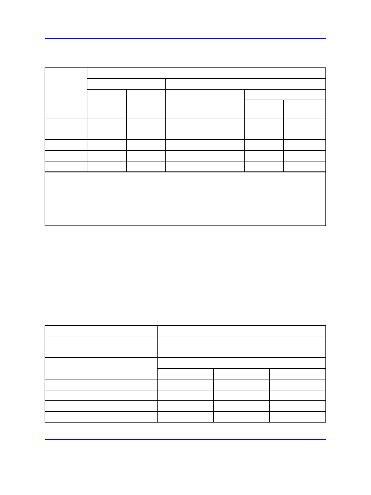
Table 33
NT8D15 E and M Trunk card (cont’d.)
Mode of operation (Note 2)
2-wire trunk 4-wire trunk
NT8D17 Conference/TDS card 93
DX tip & ring pair
Jumper
(Note 1) Type I Paging Type I Type II
J5.X off off off off (Note 4) (Note 4)
J6.X off off off off
J7.X off off off off
J8.X off off off off
J9.X Pins 2–3 Pins 2–3 Pins 2–3 Pins 2–3 Pins 1–2 Pins 1–2
Note: Jumper strap settings J1.X through J9.X apply to all 4 units; "X" indicates the unit number, 0–3.
Note: Off indicates that no jumper strap is installed on a jumper block.
Note: Paging trunk mode is not zone selectable.
Note: Jumper strap installed in this location only if external loop resistance exceeds 2500 ohms.
Note: Dot next to the jumper block indicates pin 1.
M—rcv
M—xmt
on on
on on
on on
E—rcv
M—xmt
NT8D17 Conference/TDS card
Switch and jumper settings are used to select the companding law and
to change the conference attenuation PAD levels. These PAD levels are
used if prompt CPAD = 1 in LD97. The J1 connector on the faceplate is
reserved for future use.
You can enable or disable a warning tone for conference calls. When
the option is enabled, the tone lets callers know they are entering a
conference call. The switch for this option is preset to disable the warning
tone.
Companding law
µ-law (North America), A-law connect pins 2 and 3
Special cases connect pins 1 and 2
Attenuation levels 1 2 3
10.2 db
8.5 db
6 db off
6 db off off
Nortel Communication Server 1000
Circuit Card Reference
NN43001-311 02.06 Standard
Copyright © 2003-2008 Nortel Networks
on on on
on
27 August 2008
Jumper at J3
SW2 (see Note)
off
on on
on
on
.
Page 94

94 Option settings
Companding law
4.5 db
3db
0 db off
0 db off off off
Note: Set position 4 to ON to disable the warning tone option. When the warning tone is enabled,
select the warning tone level as shown below.
Level Jumper at J2
24 db connect pins 1 and 2
30 db connect pins 2 and 3
on on
on
Jumper at J3
off off
on
off
off
NT8D21 Ringing Generator AC
Settings
Frequency Amplitude P1 P2 P3
20 Hz 86 V ac
25 Hz 70 V ac
25 Hz 80 V ac
25 Hz 86 V ac
50 Hz 70 V ac
50 Hz 80 V ac
open open
open
open
open
1–4
7–10
3–6
9–12
1–4
7–10
3–6
9–12
2–5
8–11
open open
open open
2–5
8–11
open
open
open
NT8D22 System Monitor
The master system monitor, located in the column with CP 0, must be
numbered 0. Slave system monitors are numbered from 1 to 63.
For examples of system monitor option settings in basic configurations,
see "Sample settings for NT8D22 System Monitors."
Configure the system monitor in Remote Peripheral Equipment (RPE)
columns as slaves. There is no serial connection between RPE columns.
Copyright © 2003-2008 Nortel Networks
.
Nortel Communication Server 1000
Circuit Card Reference
NN43001-311 02.06 Standard
27 August 2008
Page 95
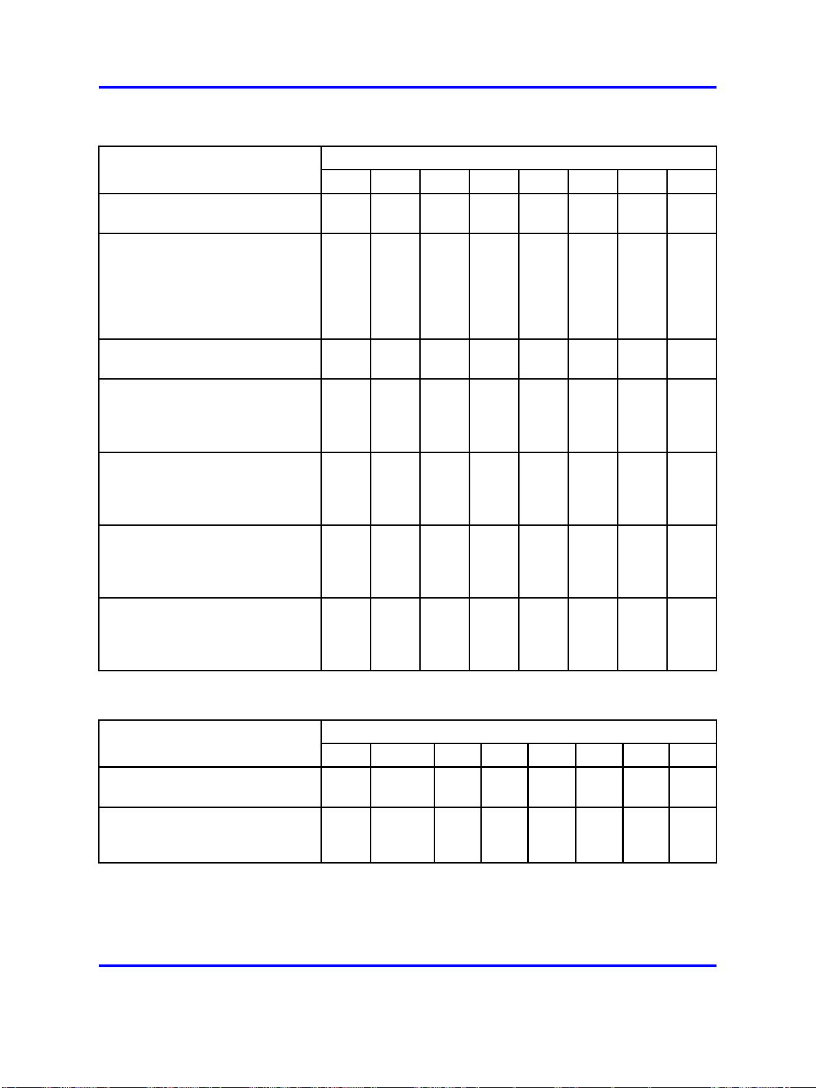
NT8D22 System Monitor 95
Table 34
NT8D22 SW1
Position
SW1 function 12345678
Not used
Meridian 1 columns only
Position 1 is OFF (Meridian 1
columns only)
Not used
Position 1 is ON, master column
contains CP:master
slaves
DC-powered system
AC-powered system
PFTU is activated by this column
due to over-temperature
PFTU is not activated by this
column
Position 1 is OFF (Meridian 1
columns only)
Not used
Not used
Position 1 is OFF (Meridian 1
columns only)
Not used
Not used
on
off
off
off
on
off
on
off
on
off
off
on
off
off
on
off
Not used
Not used
Not used
Meridian 1 columns only
on
on
off
off
Table 35
NT8D22 SW2
Position
SW2 indication 1 2 3 4 5 6 7 8
Master system monitor
Slave system monitor
Not used
All other operation
Copyright © 2003-2008 Nortel Networks
on
off
on
Always
off
Nortel Communication Server 1000
Circuit Card Reference
NN43001-311 02.06 Standard
27 August 2008
on
off
on
off
.
Page 96

96 Option settings
Table 35
NT8D22 SW2 (cont’d.)
Position
SW2 indication 1 2 3 4 5 6 7 8
For master, indicates total
number of slaves
For each slave, indicates the
slave address
Configure 3–8 according to the Table
37 "NT8D22 settings for total number of
slaves-SW2 on master" (page 96).
Configure 3–8 according to the Table
38 "NT8D22AD/NT8D22ADE5 slave
address-SW2 on slave" (page 97).
Table 36
NT8D22 SW3
SW3 indication 1 2 3 4
CTA
CTR
FAIL
MAJOR
master
slave
master
slave
master
slave
master
slave
on
off
Table 37
NT8D22 settings for total number of slaves-SW2 on master
Position
on
off
on
off
on
off
How many
slave units
0
1
2
3
4
Switch position Switch position
34
on on on on on on
on on on on on
on on on on
on on on on
on on on
5ononon
6
on on on
7ononon
8
9
10
11
Copyright © 2003-2008 Nortel Networks
on on
on on
on on
on on
How many
5
7
6
8
slave units
off
on
off
off off
on on
off
on
off
off off
off
on
off off off
on on on
off
on on
off
on
off
on
off
Nortel Communication Server 1000
NN43001-311 02.06 Standard
off
on
off
off off
Circuit Card Reference
27 August 2008
32
33
34
35
36
37
38
39
40
41
42
43
34
off
off
off
off
off
off
off
off
off
off
off
off
5
6
on on on on on
on on on on
on on on
on on on
on on
on on
on on
on on
on
on
on
on
off
off
off off
off off off
on on on
off
on on
off
on
off
on
off
7
off
on
off
off off
on on
on
off
on
off
on
off
off off
8
.
Page 97

Table 37
NT8D22 settings for total number of slaves-SW2 on master (cont’d.)
NT8D22 System Monitor 97
How many
slave units
12
13
14
15
16
17
18
19
20
21
22
23
24
25
26
27
Switch position Switch position
34
on on
on on
on on
on on
on
off
on
off
on
off
on
off
on
off
on
off
on
off
on
off
on
off off
on
off off
on
off off
on
off off
5
off off
off off
off off off
off off off off
on on on on
on on on
on on
on on
on
on
on
on
7
6
8
on on
on
off
on
off
on
off
off off
on on
off
on
off
off off
off
on
off off off
on on on
on on
on
on
off
on
off
off off
How many
slave units
44
45
46
47
48
49
50
51
52
53
54
55
56
57
58
59
34
on
off
on
off
on
off
on
off
off off
off off
off off
off off
off off
off off
off off
off off
off off off
off off off
off off off
off off off
5
off off
off off
off off off
6
7
on on
on
off
on
8
off off off off
on on on on
on on on
on on
on on
on
off
on
off
on
off off
on
off off off
off
on
off
off off
on on
on
off
on
on on on
on on
on
on
off
on
off
off off
28
29
30
31
on
off off off
on
off off off
on
off off off off
on
off off off off off
on on
on
off
on
Table 38
NT8D22AD/NT8D22ADE5 slave address-SW2 on slave
Slave unit
address
1
2
3
4
34
on on on on on
on on on on
on on on on
on on on
5ononon
6
on on on
7ononon
Copyright © 2003-2008 Nortel Networks
Position Position
5
7
6
8
Slave unit
off
on
off
off off
on on
off
on
off
off off
off
on
off off off
Nortel Communication Server 1000
Circuit Card Reference
NN43001-311 02.06 Standard
27 August 2008
60
61
62
63
address
33
34
35
36
37
38
39
off off off off
off off off off
off off off off off
on on
on
off
on
off off off off off off
34
off
off
off
off
off
off
off
5
on on on on
on on on
on on on
on on
on on
on on
on on
7
6
8
off
on
off
off off
on on
off
on
off
off off
off
on
off off off
.
Page 98
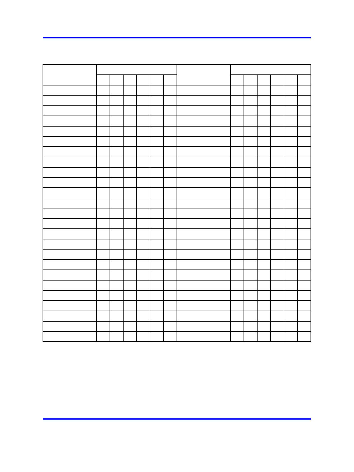
98 Option settings
Table 38
NT8D22AD/NT8D22ADE5 slave address-SW2 on slave (cont’d.)
Slave unit
address
8
9
10
11
12
13
14
15
16
17
18
19
20
21
22
34
on on
on on
on on
on on
on on
on on
on on
on on
on
off
on
off
on
off
on
off
on
off
on
off
on
off
Position Position
5
off
off
off
off
off off
off off
off off off
off off off off
on on on on
on on on
on on
on on
on
on
on
7
6
on on on
on on
on
on
off
off
off off
8
off
on
off
off off
on on
on
off
on
off
on
off
off off
on on
on
off
on
Slave unit
address
40
41
42
43
44
45
46
47
48
49
50
51
52
53
54
34
on
off
on
off
on
off
on
off
on
off
on
off
on
off
on
off
off off
off off
off off
off off
off off
off off
off off
5
6
on on on
off
on on
off
on
off
on
off
off off
off off
off off off
off off off off
on on on on
on on on
on on
on on
on
off
on
off
on
off off
7
off
on
off
off off
on on
on
off
on
off
on
off
off off
on on
on
off
on
8
23
24
25
26
27
28
29
30
31
32
on
on
on
on
on
on
on
on
on
off
on
off
off off
off off
off off
off off
off off off
off off off
off off off off
off off off off off
on on on on on
off off off
on on on
on on
on
on
NT8D22 jumper settings
EA-GND short (Pins 2 and 3 short) Accessing External EPROM.
EA-VCC short (Pins 2 and 1 short) Accessing Internal EPROM.
off
on
off
off off
on on
on
off
on
55
56
57
58
59
60
61
62
63
off off
off off off
off off off
off off off
off off off
off off off off
off off off off
off off off off off
off off off off off off
on
off off off
on on on
on on
on
on
off
on
off
off off
on on
on
off
on
Copyright © 2003-2008 Nortel Networks
.
Nortel Communication Server 1000
Circuit Card Reference
NN43001-311 02.06 Standard
27 August 2008
Page 99

NT8D41BA Quad Serial Data Interface Paddle Board 99
NT8D41BA Quad Serial Data Interface Paddle Board
Baud rate
Switches SW13, SW10, SW11, and SW12 determine the baud rate for
ports 1, 2, 3, and 4, respectively. See the configuration for these switches
in SDI paddle board baud rate switch settings.
Table 39
QSDI paddle board baud rate switch settings
SW13 (port 1), SW10 (port 2),
Baud
rate
150 2.40
300 4.80
600 9.60
1,200 19.20
2,400 38.40
4,800 76.80
9,600 153.60
19,200*
Baud Clock
(kHz) 1 2 3 4
307.20
on
on on
on
on on on
on
on on
on
on on on on
SW11 (port 3), SW12 (port 4)
off
off off
off
off off off
on on
off
on
off off
on
on
off
off
* For future use.
Address
Switch SW15 or SW16 and logic on the card always address the four
UARTs using a pair of addresses: 0 and 1, 2 and 3 through 14 and 15.
The configurations for both switches are shown in Table 40 "QSDI paddle
board address switch settings" (page 99). To avoid system problems,
switches SW15 and SW16 must not be configured identically.
Table 40
QSDI paddle board address switch settings
SW15
SW16
Device
pair
addresses
* To enable ports 1 and 2, set SW15 position 1 to ON. To enable ports 3 and 4, set SW16
position 1 to ON.
Port 1 Port 2
Port 3 Port 4 1* 2
01
23
4
6
5
7
E X off off off off off off
E X off off off off off
E X off off off off
E X off off off off
Switch settings
+
34
5
6
7
on
on on
8
on
off
+
For each X, the setting for this switch makes no difference, because it is not used.
Nortel Communication Server 1000
Circuit Card Reference
NN43001-311 02.06 Standard
Copyright © 2003-2008 Nortel Networks
27 August 2008
.
Page 100
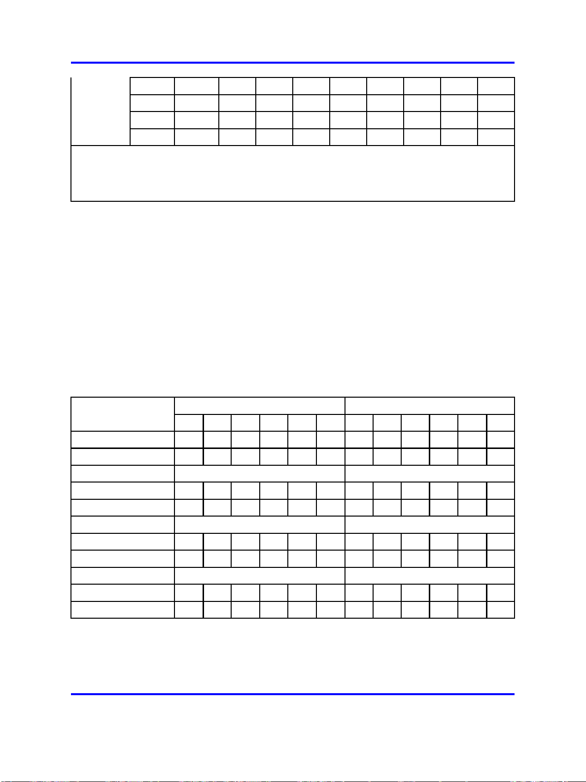
100 Option settings
89
10 11
12 13
14 15
* To enable ports 1 and 2, set SW15 position 1 to ON. To enable ports 3 and 4, set SW16
position 1 to ON.
+
For each X, the setting for this switch makes no difference, because it is not used.
E X off off off
E X off off off
E X off off off
E X off off off
on
on
on on
on on on
off off
off
DTE/DCE mode
Each serial port can be configured to connect to a terminal (DTE
equipment) or a modem (DCE equipment). Instructions for configuring
the DTE/DCE switches SW2, SW3, SW4, SW5, SW6, SW7, SW8, and
SW9 are shown in Table 41 "QSDI paddle board DTE/DCE mode switch
settings" (page 100).
Example: Port 1 is changed from DTE to DCE by reversing every switch
position on SW3 and SW2; that is, switches that were off for DTE are
turned on for DCE, and switches that were on for DTE are turned off for
DCE.
on
off
Table 41
QSDI paddle board DTE/DCE mode switch settings
Port 1 - SW 3 Port 1 -SW 2
Mode 1 2 3 4
DTE (terminal)
DCE (modem) off off off
DTE (terminal)
DCE (modem) off off off
DTE (terminal)
DCE (modem) off off off
DTE (terminal)
DCE (modem) off off off
on on on
Port 2 — SW 5 Port 2 — SW4
on on on
Port 3 — SW 7 Port 3— SW 6
on on on
Port 4 — SW 9 Port 4 — SW 8
on on on
off
on
off
on
off
on
off
on
5
on
off
on
off
on
off
on
off
61234
off off
on on
off off
on on
off off
on on
off off
on on
on
off
on
off
on
off
on
off
off
on
off
on
off
on
off
on
on
off
on
off
on
off
on
off
5
off
on
off
on
off
on
off
on
6
on
off
on
off
on
off
on
off
Copyright © 2003-2008 Nortel Networks
.
Nortel Communication Server 1000
Circuit Card Reference
NN43001-311 02.06 Standard
27 August 2008
 Loading...