

Page 1

NTRN10AN
Nortel Networks
OPTera Metro 3500
Multiservice Platform
Release 12.1 Planning and Ordering
Guide—Part 1 of 2
Standard Issue 1 April 2004
What’s inside...
Overview
Operation, administration, and maintenance (OAM) features
Hardware feature descriptions
See Part 2 for the following...
Technical specifications
Engineering rules
Cable and connector details
Shelf mounting guidelines
Ordering information
Terms and conditions
Glossary
*A0549426*
Page 2

Copyright 2000–2004 Nortel Networks, All Rights Reserved
The information contained herein is the property of Nortel Networks and is strictly confidential. Except as expressly authorized in
writing by Nortel Networks, the holder shall keep all information contained herein confidential, shall disclose the information only to
its employees with a need to know, and shall protect the information, in whole or in part, from disclosure and dissemination to third
parties with the same degree of care it uses to protect its own confidential information, but with no less than reasonable care. Except
as expressly authorized in writing by Nortel Networks, the holder is granted no rights to use the information contained herein.
Nortel Networks, the Nortel Networks logo, the Globemark, OPTera, and Preside are trademarks of Nortel Networks.
ACE/Server, RSA, and SecurID are trademarks of RSA Security Inc
Hewlett-Packard, HP, and HP-UX are trademarks of Hewlett-Packard Company.
Microsoft, Windows, and Windows NT are trademarks of Microsoft Corporation.
Solaris, Sun, Sun Blade, Sun Microsystems, and Ultra are trademarks of Sun Microsystems, Inc.
SPARC is a trademark of SPARC International Inc. Telcordia, TIRKS, and NMA are trademarks of Telcordia Technologies, Inc.
Pentium is a trademark of Intel Corporation.
.
Printed in Canada
Page 3

iii
Contents 0
About this document ix
Supported software ix
Supported hardware x
Technical support and information xii
Overview 1-1
Network element overview 1-1
Release 12.1 features 1-4
Release 12.1 Hardware Compatibility Matrix 1-16
Supported configurations 1-19
Interworking 1-25
Supported upgrade paths 1-26
Operation, administration, and maintenance (OAM) features 2-1
Gigabit Ethernet Drop and Continue 2-3
Alarm provisioning 2-5
Alarm flow control 2-6
Environmental alarms 2-7
External controls 2-7
ACO switch — clearing audible alarms and performing lamp tests 2-7
Bandwidth management 2-7
Tributary, DWDM, BLSR, UPSR, and 1+1 linear point-to-point 2-8
BLSR 2-9
Connection editing 2-9
In-service traffic rollover 2-9
BLSR networks (2-fiber) 2-10
Protection 2-11
’Infinite wait-to-restore’ parameter 2-12
BLSR Line Protection Oscillation Control 2-13
BLSR single span fiber cut scenario 2-13
BLSR nodal / multi-span failure scenario (involves squelching) 2-25
BLSR configurations 2-29
BLSR configuration and connection audit 2-30
Traffic flow over OC-48 BLSR 2-31
Traffic flow over OC-192 BLSR 2-32
Provisioning rules 2-34
OAM supported on BLSR 2-43
Channelized DS3 service (DS3VTx12 mapper) 2-44
Planning and Ordering Guide—Part 1 of 2 NTRN10AN Rel 12.1 Standard Iss 1 Apr 2004
Page 4

iv Contents
Common Language Location Identifier 2-44
Connection ID 2-45
Consolidated load 2-45
Dense wavelength division multiplexing (DWDM) 2-46
OMX module 2-48
Network sites 2-49
DWDM configurations 2-50
Facility attributes 2-54
Loopbacks 2-54
Terminal loopback 2-54
Facility loopback 2-54
Optical loopback 2-55
Network surveillance 2-58
Extended network processor (NPx) 2-58
Telemetry byte-oriented serial (TBOS) 2-59
Path trace 2-60
Section trace 2-61
TID address resolution protocol (TARP) 2-61
OPTera Packet Edge System (Resilient Packet Ring) - Ethernet 2-62
Connectors 2-62
Resilient packet ring (RPR) object 2-63
Optical Ethernet / Layer 2 (OE/L2) on OPTera Packet Edge System 2-64
RPR configuration alert 2-65
Auto save notification 2-65
NNI Filters increased to 2048 2-66
Optical Ethernet-Private Line (OE-PL) services using 10/100 Ethernet 2-66
2x100BT-P2P circuit pack 2-66
PPP over SONET 2-67
PPP and HDLC 2-67
Bridge Control Protocol 2-69
Network protection using UPSR, 1+1 linear and BLSR 2-69
OAMP support 2-70
Ethernet Operational Measurements 2-70
Optical Ethernet-Private Line (OE-PL) service using 2x1000 SX/LX OPE circuit
packs 2-71
Distributed multilink trunking 2-72
Bandwidth Reservation Protocol (BRP) 2-72
1024 TDIs on a mapped UNI 2-72
Optical Ethernet - Private Line (OE-PL) and Storage applications 2-73
2xGigE/FC-P2P circuit pack 2-73
Alarm management 2-74
Bandwidth management 2-84
Facility attributes 2-85
Ethernet Operational Measurements 2-90
Performance Monitoring 2-95
Fibre Channel Extended Reach 2-95
Generic Framing Procedure and Virtual Concatenation support 2-99
Optical interoperability of OPTera Metro 3500 2-102
Performance monitoring 2-102
SONET line, section, and path parameters 2-102
Threshold values 2-103
OPTera Metro 3500 Multiservice Platform NTRN10AN Rel 12.1 Standard Iss 1 Apr 2004
Page 5

Retrieving performance monitoring counts 2-110
Physical PMs 2-111
Performance monitoring threshold crossing alerts (TCA) 2-114
TCAs 2-114
TCA summary alarms 2-114
Site Manager support 2-116
Preside Software Upgrade Management support 2-116
Preside Applications Platform and Multiservice MOA support 2-117
Protection switching 2-118
Protection hierarchy 2-119
Protection performance monitoring parameters for optical facilities 2-120
Security and administration 2-122
Local account user authentication 2-122
Local ‘challenge-response’ user authentication 2-123
Centralized Security Administration (CSA) 2-124
Centralized user administration and authentication through RADIUS 2-125
SecurID support 2-128
Secure storage of authentication data 2-128
Saving and restoring provisioning data 2-129
Local TL1 of provisioning data 2-129
Save and restore of shelf processor or span of control data to a remote
management entity through an IP connection 2-129
Application of TL1 commands from a TL1 script file 2-130
Security levels 2-130
Third Level 5 User Support/Increased NPx SOC visibility to 16 NEs 2-131
System identifier (SID) 2-131
Remote login 2-132
Multiple login sessions 2-132
Enhanced Intrusion Detection 2-133
Intrusion attempt handling 2-134
Password management 2-135
Customer managed networks 2-137
Security log audit trail 2-138
General Broadcast tool 2-139
Modifiable Login Banner 2-140
STS Managed DSM 2-142
Support for 12 DSM 2-146
Synchronization 2-146
Internal timing 2-147
External timing 2-147
Line timing 2-147
Timing modes 2-149
Stratum clocks 2-150
Synchronization hierarchy 2-150
Hierarchy violations 2-151
Timing loops 2-151
Building-integrated timing supply (BITS) 2-153
Network element synchronization modes 2-153
Timing sources and timing distribution 2-155
External timing reference input signals to STX and VTX-series circuit packs
2-156
Contents v
Planning and Ordering Guide—Part 1 of 2 NTRN10AN Rel 12.1 Standard Iss 1 Apr 2004
Page 6

vi Contents
Synchronization-status messages 2-156
User-specified quality levels for timing sources 2-158
BITS output with VTX-series or STX-192 circuit packs 2-158
User-initiated synchronization switches 2-158
Test Access 2-160
Test Access Ports (TAPs) 2-161
Test access configurations 2-162
Monitoring test access 2-162
Split test access 2-165
Loss of association and auto recovery 2-167
User interface 2-168
Time of day synchronization 2-169
TL1 Changes to Cross Connect AID parameter 2-172
TL1 event exerciser 2-173
TL1 event / log feature 2-173
Database change events 2-174
Log events 2-174
Inventory events 2-174
ATAG sequence numbers 2-175
Topology enhancements 2-175
VT management option on STX equipped OPTera Metro 3500 2-175
VT management on a UPSR 2-175
VT grooming on a UPSR 2-181
Collocated OPTera Metro 3000 NE and dedicated STS at each site 2-184
Collocated OPTera Metro 3000 NE and shared VT-managed STS 2-186
UPSR planning guidelines summary 2-189
General guidelines 2-189
Physical subtending rings 2-189
Virtual rings across the STS-managed OPTera Metro 3500 backbone
network 2-189
VT grooming at an STS-managed OPTera Metro 3500 site 2-189
Hardware feature descriptions 3-1
Extended Reach (ZX) Small Form Factor Pluggable (SFP) 3-3
OPTera Metro 3500 Shelf and the OPTera Metro 3500 Universal Shelf 3-4
Shelves equipped with VTX-48 or VTX-48e circuit packs 3-4
Shelves equipped with STX-192 circuit packs 3-5
Replaceable I/O modules 3-26
Common modules 3-37
Left OAM (LOAM) 3-37
Left interface (LIF) 3-38
OPTera Metro 3500 cooling unit assembly and cooling unit fan modules 3-40
Universal cooling unit assembly and cooling unit fan modules for extended
temperature applications 3-41
20 A (Universal) power module 3-42
OPTera Metro 3000 breaker interface panel (BIP) 3-42
OPTera Metro 3500 BIP (European deployment) 3-44
STX-192 circuit pack 3-51
Equipping rules 3-51
VTX-48 circuit pack 3-54
Equipping rules 3-55
OPTera Metro 3500 Multiservice Platform NTRN10AN Rel 12.1 Standard Iss 1 Apr 2004
Page 7

VTX-48e circuit pack 3-55
Equipping rules 3-56
Extended shelf processor (SPx) 3-56
TL1 sessions 3-56
Alarms and TBOS 3-57
Reset button 3-57
Section data communication channel (SDCC) 3-57
Equipping rules 3-57
Extended network processor (NPx) 3-57
TL1 sessions 3-58
Alarms and provisioning data 3-58
Reset button 3-58
Equipping rules 3-59
ILAN interface 3-59
Equipping rules 3-59
OC-192 optical interface circuit pack 3-59
STS-1 path trace for OC-192 3-60
Section trace for OC-192 3-60
Section data communication channel (SDCC) 3-60
Forward Error Correction (FEC) 3-60
Equipping rules 3-62
OC-192 protection switching 3-62
OC-192 DWDM G.709 FEC optical interface circuit pack 3-64
Section data communication channel (SDCC) 3-64
Forward Error Correction (FEC) 3-64
Equipping rules 3-65
OC-48 optical interface circuit pack 3-65
STS-1 path trace for OC-48 3-65
Section trace for OC-48 3-66
Section data communication channel (SDCC) 3-66
Equipping rules 3-66
OC-48 protection switching 3-67
OC-48 STS optical interface circuit pack 3-68
STS-1 path trace for OC-48 3-69
Section trace for OC-48 3-69
Section data communication channel (SDCC) 3-69
Equipping rules 3-70
OC-48 protection switching 3-70
OC-48 DWDM circuit pack 3-71
Section data communication channel (SDCC) 3-71
Equipping rules 3-72
OC-12 optical interface circuit pack 3-72
Equipping rules 3-73
OC-12 Protection switching 3-73
Section data communication channel (SDCC) 3-74
OC12x4 STS IR optical interface circuit pack 3-75
Multimode Interworking 3-75
Equipping rules 3-76
Section data communication channel (SDCC) 3-77
OC-3 optical interface circuit pack 3-77
Equipping rules 3-78
Contents vii
Planning and Ordering Guide—Part 1 of 2 NTRN10AN Rel 12.1 Standard Iss 1 Apr 2004
Page 8

viii Contents
OC-3 Protection switching 3-78
Section data communication channel (SDCC) 3-79
OC-3x4 optical interface circuit pack 3-80
Multimode Interworking 3-80
Equipping rules 3-81
Section data communication channel (SDCC) 3-82
EC-1x3 circuit pack 3-82
Equipping rules 3-83
Protection switching 3-83
Section data communication channel (SDCC) 3-83
EC-1x12 circuit pack 3-84
Equipping rules 3-84
Protection switching 3-85
Section data communication channel (SDCC) 3-85
DS1 mapper 3-86
Equipping rules 3-86
DS3x3 mapper 3-87
Equipping rules 3-87
Protection switching 3-88
DS3x12 / DS3x12e mapper 3-89
Equipping rules 3-89
DS3VTx12 mapper 3-90
Equipping rules 3-91
DS3/VT protection switching 3-91
2x100BT-P2P circuit pack 3-91
Equipping rules 3-92
OPTera Packet Edge System 4x100BT circuit pack 3-94
Equipping rules 3-94
OPTera Packet Edge System 4x100FX circuit pack 3-96
Equipping rules 3-96
OPTera Packet Edge System 2xGigE (2x1000SX, 2x1000LX) circuit pack 3-97
Equipping rules 3-97
2xGigabit Ethernet/Fibre Channel - Point-to-Point circuit pack 3-98
Equipping rules 3-98
Protection switch controller (PSC) 3-100
Equipping rules 3-100
Protection switch extender (PSX) 3-101
Equipping rules 3-101
OMX + Fiber Manager 4CH 3-101
Enhanced OMX + Fiber Manager 4CH 3-102
OMX shelf (not required with OMX + Fiber Manager 4CH) 3-103
Equipping rules 3-103
Fiber Manager (not required with OMX + Fiber Manager 4CH) 3-104
DS1 service module (DSM) shelf 3-107
Equipping rules 3-107
Multiple IS 3-107
DSM DS1x84 termination module (TM) 3-111
Equipping rules 3-111
Protection switching 3-112
OPTera Metro 3500 Multiservice Platform NTRN10AN Rel 12.1 Standard Iss 1 Apr 2004
Page 9

ix
About this document 0
ATTENTION
This document is presented in two parts: Part 1 and Part 2. Each part has its
own table of contents. The table of contents in Part 1 contain topics found in
Part 1 only. The table of contents in Part 2 contain topics found in Part 2 only.
Part 2 continues sequential chapter numbering from Part 1.
You are reading Part 1 of Nortel Networks OPTera Metro 3500 Multiservice
Platform Release 12.1 Planning and Ordering Guide, NTRN10AN.
Part 1 of OPTera Metro 3500 Multiservice Platform Release 12.1 Planning
and Ordering Guide, NTRN10AN covers a network element overview and
new features in Release 12.1, operation, administration, and maintenance
(OAM) features, and hardware description features.
Part 2 of OPTera Metro 3500 Multiservice Platform Release 12.1 Planning
and Ordering Guide, NTRN10AN covers technical specifications, engineering
rules, cable and connector details, shelf mounting guidelines, ordering
information, terms and conditions, and a glossary.
Standards
The Telecommunications Industry Association (TIA) and the Electronics
Industries Alliance (EIA) accepted RS-232 as a standard in 1997 and
renumbered this standard as TIA/EIA-232. In this document, RS-232 is used
to reflect current labels on the hardware and in the software for the OPTera
Metro 3500 Multiservice Platform.
Supported software
This document supports the software release for OPTera Metro 3500 Release
12.1.
Planning and Ordering Guide—Part 1 of 2 NTRN10AN Rel 12.1 Standard Iss 1 Apr 2004
Page 10

x About this document
Supported hardware
This document supports the OPTera Metro 3500 shelves (NTN476AA,
NTN476DA) and the Universal OPTera Metro 3500 shelf (NTN476AH).
Note: The OPTera Metro 3500 shelf NTN476AA must be upgraded using
the power module and cooling upgrade kit (NTN458MW) to support
OC-192 optical interfaces.
Hardware naming conventions
The following naming conventions are used throughout this document to
identify the OPTera Metro 3500 hardware:
• The extended shelf processor (SPx) is referred to as the shelf processor.
• The extended network processor (NPx) is referred to as the network
processor.
Audience
The following members of your company are the intended audience of this
Nortel Networks technical publication (NTP):
• planners
• provisioners
• network administrators
• transmission standards engineers
OPTera Metro 3500 Multiservice Platform NTRN10AN Rel 12.1 Standard Iss 1 Apr 2004
Page 11
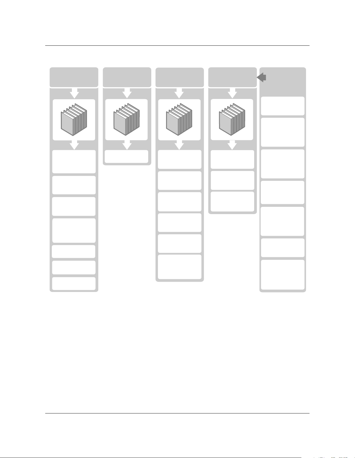
OPTera Metro 3500 NTP library
Shelf Setup
About the
OPTera Metro 3500
NTP Library
(323-1059-090)
Planning and
Ordering Guide
(NTRN10AN)
Network
Interworking Guide
(NTCA68CA)
OPTera Metro 3500
Network
InteroperabilityGuide
(NTRN16AA)
Installation
(323-1059-201)
Commissioning
(323-1059-210)
System Testing
(323-1059-222)
TL1 ReferenceGuides and
TL1 Reference
(323-1059-190)
Operations,
Administration
and Provisioning
System
Reconfiguration
(323-1059-224)
Security and
Administration
(323-1059-302)
Provisioning
Synchronization
(323-1059-310)
Protection
Switching
(323-1059-311)
Bandwidth
Management
(323-1059-320)
Provisioning
Equipment and
Facilities
(323-1059-350)
Maintenance
Performance
Monitoring
(323-1059-510)
Network
Surveillance
(323-1059-520)
Alarm and
Trouble Clearing
(323-1059-543)
About this document xi
EX1541p
Supporting
documentation
for the OPTera
Metro 3500
Library
Change Application
Procedures
(CAPs)
Data
Communications
Network Planning
Guide
(NTR710AM)
OPTera Metro
3000 series
DWDM Application
Guide
(NTRN12AA)
OPTera Packet Edge
System Planning
Guide
(NTRN10YK)
OPTera Packet Edge
System Network
Applications and
Management
(NTRN11YK)
OPTera Packet Edge
System User Guide
(NTN465YG)
Site Manager
Planning and
Installation Guide,
Rel 6.0
(NTNM35FA)
Planning and Ordering Guide—Part 1 of 2 NTRN10AN Rel 12.1 Standard Iss 1 Apr 2004
Page 12

xii About this document
Technical support and information
For technical support and information from Nortel Networks, refer to the
following table.
Technical Assistance Service
For service-affecting problems:
For 24-hour emergency recovery or software upgrade
support, that is, for:
• restoration of service for equipment that has been carrying
traffic and is out of service
• issues that prevent traffic protection switching
• issues that prevent completion of software upgrades
For non-service-affecting problems:
For 24-hour support on issues requiring immediate support
or for 14-hour support (8 a.m. to 10 p.m. EST) on upgrade
notification and non-urgent issues.
Global software upgrade support: North America:
North America:
1-800-4NORTEL (1-800-466-7835)
International:
001-919-992-8300
North America:
1-800-4NORTEL (1-800-466-7835)
Note:
code (ERC). To determine the ERC, see
our corporate Web site at
www.nortelnetworks.com. Click on the
Express Routing Codes link.
International:
Varies according to country. For a list of
telephone numbers, see our corporate
Web site at www.nortelnetworks.com.
Click on the Contact Us link.
1-800-4NORTEL (1-800-466-7835)
International:
Varies according to country. For a list of
telephone numbers, see our corporate
Web site at www.nortelnetworks.com.
Click on the Contact Us link.
You require an express routing
OPTera Metro 3500 Multiservice Platform NTRN10AN Rel 12.1 Standard Iss 1 Apr 2004
Page 13

1-1
Overview 1-
Network element overview
The Nortel Networks OPTera Metro 3500 network element is a multiservice
platform offering dense wavelength division multiplexing (DWDM) with a
wide variety of services: DS1, DS3, Channelized DS3, EC-1, OC-3, OC-12,
OC-48, OC-192, 10/100BASE-T Ethernet, 100BASE-FX Ethernet, Gigabit
Ethernet and Fibre Channel.
OPTera Metro 3500 is a next generation SONET multiservice platform. It
provides full OC-192 connectivity to customer premise locations.
On the physical layer (layer 1), an OPTera Metro 3500 network can be
configured as a unidirectional path-switched ring (UPSR), a 1+1 linear
configuration, a 2-fiber bidirectional line-switched ring (BLSR), or as an
unprotected fiber optic run.
On the data link layer (layer 2), an OPTera Metro 3500 network can be
configured as an OPTera Packet Edge ring with layer 2 protection, in
accordance with Resilient Packet Rings (RPR) currently being defined by the
IEEE 802.17 working group.
OPTera Metro Release 12.0 introduced a new STX-192 switch matrix circuit
pack. The STX-192 circuit pack is a fully non-blocking STS switch matrix and
clocking module providing switching capability for 40 Gbit/s. The STX-192
provides support for 10 Gbit/s links to the line slots 11 and 12 and up to 2.5
Gbit/s links to slots 3 through 10.
For STX based configurations, the OPTera Metro 3500 is optimized for
broadband services, namely Gigabit Ethernet, Storage Area Networking, and
switched Ethernet services using Resilient Packet Ring. When configured for
STX based configurations, the platform supports full TDM services as well,
with full fill OC12 and OC48 densities. Furthermore, DS1 services are still
possible via the DS1 Service Module (DSM). For STX based configurations
where VT1.5 level management is required, a dual node configuration can be
used where by a VTX based OPTera Metro 3500 is subtended from a STX
based OPTera Metro 3500. Both nodes are managed via Site Manager, which
provides end-to-end connection management capability.
Planning and Ordering Guide—Part 1 of 2 NTRN10AN Rel 12.1 Standard Iss 1 Apr 2004
Page 14
1-2 Overview
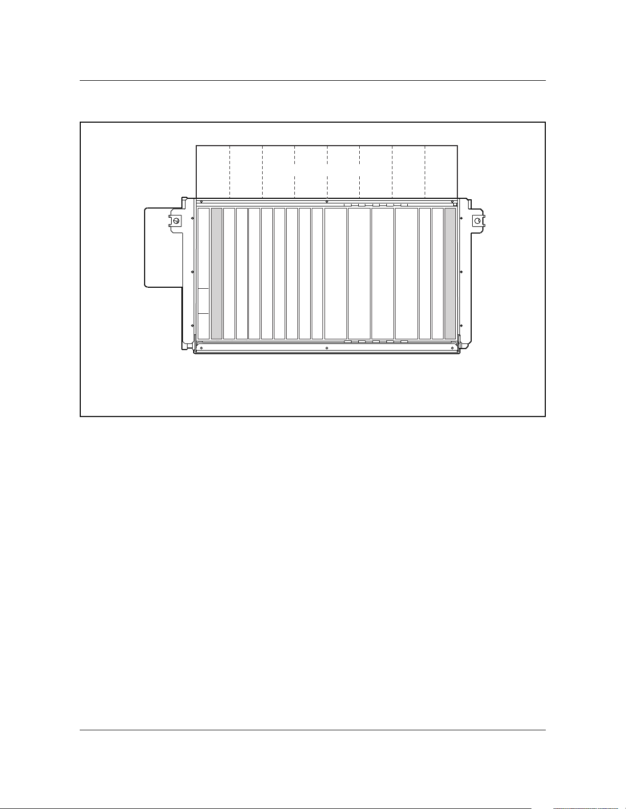
Figure 1-1
OPTera Metro 3500 slot assignments (STX-192 installed in shelf)
Slot 3 Slot 4 Slot 5 Slot 6 Slot 7 Slot 8 Slot 9 Slot 10
I/O module slots
LOAM
EX1470p
Empty
Tributary
Tributary
Tributary
Tributary
Tributary
Tributary
Tributary
Tributary
(See Note)
(See Note)
OC-48 STS or OC-192
OC-48 STS or OC-192
Pwr B Pwr A LIF
Slot 1
Slot 2
Slot 4
Slot 3
Note:
The OC-48 STS circuit pack is a single-width circuit pack.
Slot 6
Slot 5
Slot 7
Slot 9
Slot 8
Slot 10
Slot 11
Slot 12
STX-192
Slot 13
SPx
STX-192
Slot 15
Slot 14
Empty
NPx or ILAN
Slot 17
Slot 16
For VTX based configurations, the OM3500 is optimized for OC48 based
TDM and Optical Ethernet applications, supporting full densities for all TDM
services. Furthermore, with the completely non-blocking VT1.5 switch
matrix, the platform is ideally suited for hybrid digital cross connect and
add/drop multiplexer applications.
OPTera Metro 3500 Multiservice Platform NTRN10AN Rel 12.1 Standard Iss 1 Apr 2004
Page 15
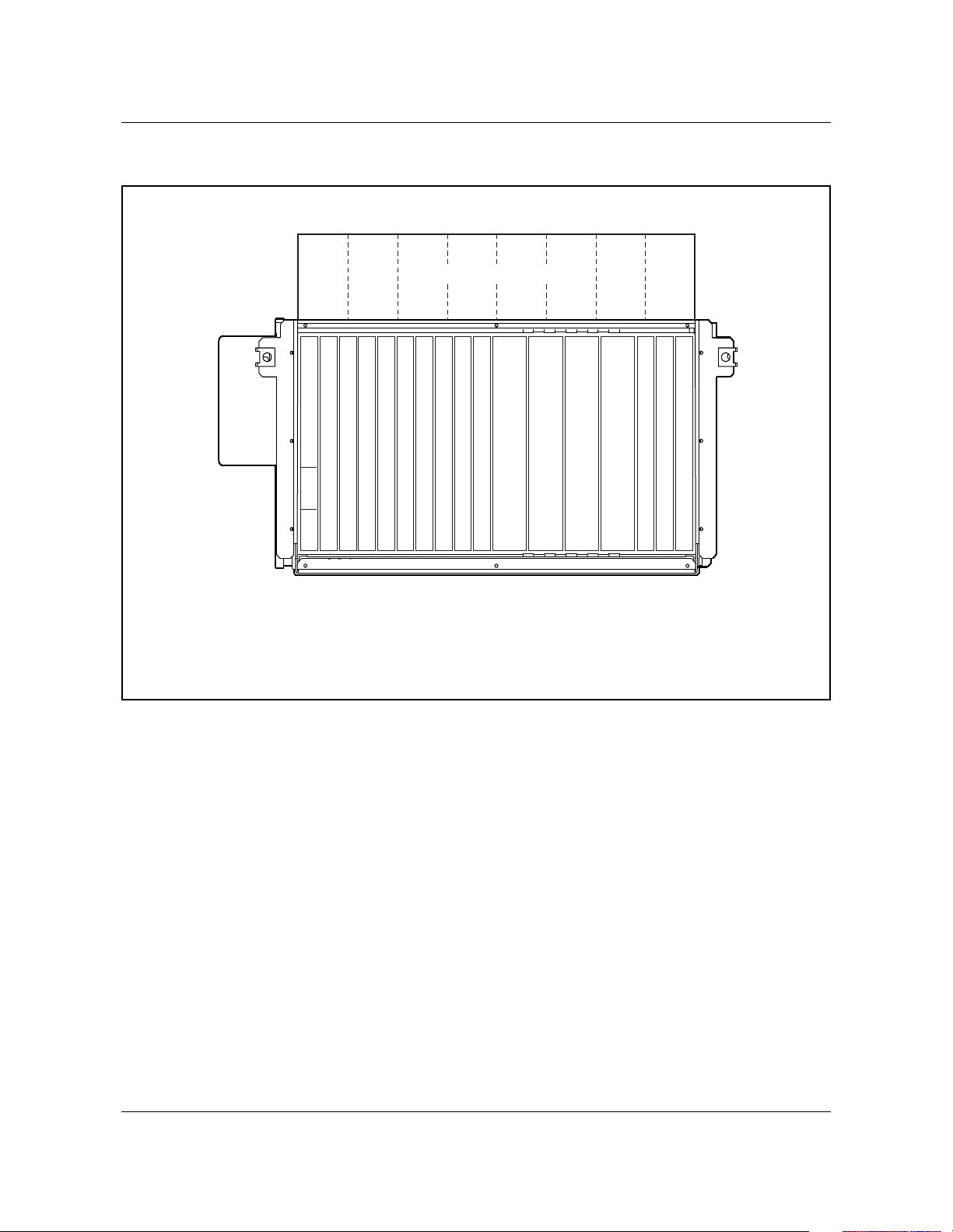
Figure 1-2
OPTera Metro 3500 slot assignments (VTX-48/VTX-48e installed in shelf)
Slot 3 Slot 4 Slot 5 Slot 6 Slot 7 Slot 8 Slot 9 Slot 10
I/O module slots
LOAM
Pwr B Pwr A LIF
PSC
Tributary
Tributary
Tributary
Tributary
Tributary
Tributary
Tributary
Tributary
OC-48 or OC-12
(See Note)
(See Note)
OC-48 or OC-12
VTX-48
VTX-48
SPx
NPx or ILAN
Overview 1-3
EX1040p
PSX
Slot 1
Slot 2
Slot 4
Slot 3
Note:
The OC-12 circuit pack is a single-width circuit pack.
Slot 6
Slot 5
Slot 7
Slot 9
Slot 8
Slot 10
Slot 11
Slot 12
Slot 13
Slot 14
Slot 16
Slot 15
Slot 17
Planning and Ordering Guide—Part 1 of 2 NTRN10AN Rel 12.1 Standard Iss 1 Apr 2004
Page 16

1-4 Overview
Release 12.1 features
The Release 12.1 OPTera Metro 3500 system offers the following new and
enhanced features:
• Gigabit Ethernet Drop and Continue support on 2xGigE/FC-P2P interface
• Support for extended reach (ZX) small-form factor pluggable (SFP)
This document describes the applications and functionality available in
Release 12.1. See the following chapters for more detail:
• Chapter 1, Overview, gives a high level description of what is supported in
this release.
• Chapter 2, Operation, administration, and maintenance (OAM) features,
gives a high level description of OAM&P functionality.
• Chapter 3, Hardware feature descriptions, describes both shelves and their
components.
• Chapter 4, Technical specifications (in Part 2 of this guide), lists the
technical specifications for all circuit packs and equipment.
• Chapter 5, Engineering rules (in Part 2 of this guide), lists special
engineering rules for interworking, DWDM, and Preside.
• Chapter 6, Cable and connector details (in Part 2 of this guide), lists the
cables and components used on the shelf.
• Chapter 7, Shelf mounting guidelines (in Part 2 of this guide), describes
typical installations.
• Chapter 8, Ordering information (in Part 2 of this guide), provides
procedures and tables to simplify the ordering process.
• Chapter 9, Terms and conditions (in Part 2 of this guide), provides contacts
to set up an order.
See Table 1-1 for a complete list of supported features in Release 12.1.
Table 1-1
Feature compatibility for Release 12.1
Feature Supported on
platforms with
VTX-series
circuit packs
Network configurations
Bidirectional line switched ring (BLSR) (2-fiber) at OC-192 rate No Yes
Bidirectional line switched ring (BLSR) (2-fiber) at OC-48 rate Yes No
Supported on
platforms with
STX circuit packs
BLSR with linear spur Yes Yes
BLSR with subtending UPSR Yes Yes
OPTera Metro 3500 Multiservice Platform NTRN10AN Rel 12.1 Standard Iss 1 Apr 2004
Page 17

Table 1-1 (continued)
Feature compatibility for Release 12.1
Overview 1-5
Feature Supported on
platforms with
VTX-series
Supported on
platforms with
STX circuit packs
circuit packs
Uni-directional Path switched Ring at OC3, OC-12, OC-48 or
OC-192 rates
Yes
except OC-192
Yes
Dual-homed subtending rings (on UPSR) Yes Yes
Linear add/drop multiplexer OC-3, and OC-12, OC-48, and
OC-192 rates
Linear point-to-point at OC-3, OC-12, OC-48, and OC-192
rates
Yes
except OC-192
Yes
except OC-192
Yes
except OC-192
Yes
Matched nodes (on UPSR) Yes Yes
Mixed RPR and TDM traffic over BLSR Yes Yes
Mixed RPR and TDM traffic over UPSR (and above UPSR
Yes Yes
variants)
Optical hubbing Yes Yes
Path-in-line (virtual ring) (across UPSR or BLSR) Yes Yes
RPR over BLSR (working and protection channels) Yes Yes
RPR over UPSR (and above UPSR variants) Yes Yes
Single-homed subtending rings (on UPSR) Yes Yes
UPSR to non-OPTera Metro 3500 BLSR interconnection Yes Yes
In-service reconfigurations
Adding a network element to an OC-48 or OC-192 BLSR Yes
except OC-192
Adding a network element to a UPSR Yes
Yes
except OC-48
Yes
except OC-192
Adding an OMX shelf to an in-service DWDM network Yes Yes
Adding an OPTera Metro 3500 network element to an OC-48
Yes Yes
UPSR over DWDM
Adding an OPTera Metro 3500 network element to an OC-48
Yes No
BLSR over DWDM
Converting an OC-48 UPSR to an OC-48 UPSR over DWDM Yes Yes
Converting an OC-48 BLSR to an OC-48 BLSR over DWDM Yes No
Planning and Ordering Guide—Part 1 of 2 NTRN10AN Rel 12.1 Standard Iss 1 Apr 2004
Page 18

1-6 Overview
Table 1-1 (continued)
Feature compatibility for Release 12.1
Feature Supported on
platforms with
VTX-series
Supported on
platforms with
STX circuit packs
circuit packs
Converting an OC-48 linear point-to-point network to an
Yes Yes
OC-48 linear point-to-point network over DWDM
Adding an OPTera Metro 3500 network element to an OC-192
No Yes
UPSR over DWDM
Converting an OC-192 UPSR to an OC-192 UPSR over
No Yes
DWDM
Converting an OC-192 linear point-to-point network to an
No Yes
OC-192 linear point-to-point network over DWDM
Converting a UPSR to a BLSR Yes
See Note 3
Converting a 1+1 linear point-to-point configuration to a
Yes Yes
Yes
See Note 3
2-node UPSR
Converting a 2-node UPSR to a 1+1 linear point-to-point
Yes Yes
configuration
Moving a synchronization boundary Yes Yes
Removing a network element from an OC-48 or OC-192 BLSR Yes
except OC-192
Yes
except OC-48
Removing a network element from a UPSR Yes Yes
Removing an OPTera Metro 3500 network element from an
Yes No
OC-48 BLSR over DWDM
Removing an OPTera Metro 3500 network element from an
Yes Yes
OC-48 UPSR over DWDM
Replacing a DS3x3 mapper with a DS3x12 / DS3x12e mapper Yes Yes
Replacing an EC-1x3 circuit pack with an EC-1x12 circuit pack Yes Yes
Replacing the ILAN circuit pack with a network processor Yes Yes
Replacing the network processor with an ILAN circuit pack Yes Yes
Upgrading a fiber span from an OC-3 to an OC-12 rate
Yes Yes
(See Note 2)
Upgrading a fiber span from an OC-12 to an OC-48 rate
Yes Yes
(See Note 2)
OPTera Metro 3500 Multiservice Platform NTRN10AN Rel 12.1 Standard Iss 1 Apr 2004
Page 19

Table 1-1 (continued)
Feature compatibility for Release 12.1
Overview 1-7
Feature Supported on
platforms with
VTX-series
Supported on
platforms with
STX circuit packs
circuit packs
Upgrading a fiber span from an OC-48 to an OC-192 rate No Yes
See Note 3
Converting a VT-assigned BLSR connection to a Full VT
Yes No
BLSR connection
Converting a Full VT BLSR connection to a VT-assigned
Yes No
BLSR connection
Services
DS1 Yes Yes
DS3 Yes Yes
DS3 (Channelized) Yes No
EC-1 Yes Yes
OC-3 Yes Yes
OC-12 Yes Yes
OC-48 Yes Yes
OC-192 No Yes
Optical Ethernet - Private Line service using 10/100 Ethernet Yes Yes
Optical Ethernet - Private Line using Gigabit Ethernet Yes Yes
full rate support
OPTera Packet Edge System
Yes Yes
See:
• OPTera Metro 3000 OPTera Packet Edge System User Guide
(NTN465YG)
• OPTera Packet Edge System Planning Guide (NTRN10YK)
• OPTera Packet Edge System Network Applications and
Management (NTRN11YK)
Resilient Packet Ring (RPR) Yes Yes
Storage Network (Fibre Channel (FC100) & FICON) Yes Yes
Test Access Electrical and Optical TAPS (monitor and split
Yes Yes
states)
Hardware (See Note 2)
Planning and Ordering Guide—Part 1 of 2 NTRN10AN Rel 12.1 Standard Iss 1 Apr 2004
Page 20

1-8 Overview
Table 1-1 (continued)
Feature compatibility for Release 12.1
Feature Supported on
platforms with
VTX-series
Supported on
platforms with
STX circuit packs
circuit packs
OPTera Metro 3500 Shelf Assembly (NTN476AA) Yes Yes
See Note 4
OPTera Metro 3500 Shelf Assembly (NTN476DA) Yes Yes
OPTera Metro 3500 Universal Shelf Assembly (NTN476AH) Yes Yes
2x100BT-P2P circuit pack (NTN433AA) Yes Yes
4x100FX (NTN4333EA, NTN433FA) Yes Yes
4x100BT (NTN433BB) Yes Yes
2x1000SX (NTN438AA) Yes Yes
2x1000LX (NTN438BA) Yes Yes
2xGigE/FC-P2P (NTN438DA) Yes Yes
1000-BaseSX 850 nm SFP (NTTP51AA) Yes Yes
1000-BaseLX 1310 nm SFP (NTTP51BD) Yes Yes
1000-BaseZX 1550 nm SFP (NTTP51DZ) Yes Yes
DS1 mapper (1:N protection) Yes No
DS1 service module (DSM) (up to 12 protected or unprotected
Yes Yes
DSM on an NE)
DS3 mapper
No No
See Note 5
DS3VTx12 mapper Yes No
DS3x12 mapper (1+1 protection) Yes Yes
DS3x12e mapper (1+1 protection) Yes Yes
DS3x3 mapper (1+1 protection) (NTN437AA) Yes Yes
DSM DS1x84 termination module (TM) Yes Yes
EC-1 circuit pack
No No
See Note 5
EC-1x12 circuit pack (1+1 protection) Yes Yes
EC-1x3 circuit pack (1+1 protection) (NTN436AA) Yes Yes
OPTera Metro 3500 Multiservice Platform NTRN10AN Rel 12.1 Standard Iss 1 Apr 2004
Page 21

Table 1-1 (continued)
Feature compatibility for Release 12.1
Overview 1-9
Feature Supported on
platforms with
VTX-series
circuit packs
OC-3 circuit pack in slots 11 and 12 (UPSR, 1+1 linear
No No
point-to-point and 1+1 linear ADM)
OC-3 circuit pack in slots 3 through 10 (UPSR, 1+1 linear
Yes Yes
point-to-point and 1+1 linear ADM)
OC-3x4 circuit pack in slots 11 and 12 (UPSR, 1+1 linear
No No
point-to-point and 1+1 linear ADM)
OC-3x4 circuit pack in slots 3 through 10 (UPSR, 1+1 linear
Yes Yes
point-to-point and 1+1 linear ADM)
OC-12 circuit pack in slots 11 and 12 (UPSR, 1+1 linear
Yes No
point-to-point and 1+1 linear ADM)
OC-12 circuit pack in slots 3 through 10 (UPSR, 1+1 linear
Yes Yes
point-to-point and 1+1 linear ADM)
OC-12x4 STS circuit pack in slots 11 and 12 (UPSR, 1+1
No No
linear point-to-point and 1+1 linear ADM)
OC-12x4 STS circuit pack in slots 3 through 10 (UPSR, 1+1
No Yes
linear point-to-point and 1+1 linear ADM)
Supported on
platforms with
STX circuit packs
OC-48 circuit pack in slots 11 and 12 (BLSR, UPSR, 1+1 linear
point-to-point)
OC-48 circuit pack in slots 3 through 10 (UPSR, 1+1 linear
point-to-point)
OC-48 STS circuit pack in slots 3 to 12 (UPSR, 1+1 linear
point-to-point)
OC-48 DWDM circuit pack in slots 11 and 12 (BLSR, UPSR,
1+1 linear point-to-point)
OC-48 DWDM circuit pack in slots 3 through 10 (UPSR, 1+1
linear point-to-point)
OC-192 circuit pack in slots 11 and 12 (BLSR, UPSR, 1+1
linear point-to-point)
OC-192 circuit pack in slots 3 through 10 (UPSR, 1+1 linear
point-to-point)
STM-0 optical interface (1+1 protection) (in J-SDH mode)
See Note 5
Planning and Ordering Guide—Part 1 of 2 NTRN10AN Rel 12.1 Standard Iss 1 Apr 2004
Yes No
No No
No Yes
Yes No
No No
No Yes
No No
No No
Page 22

1-10 Overview
Table 1-1 (continued)
Feature compatibility for Release 12.1
Feature Supported on
platforms with
VTX-series
Supported on
platforms with
STX circuit packs
circuit packs
STM-1 optical interface (1+1 protection) (in J-SDH mode)
No No
See Note 5
STM-1x4 optical interface (in J-SDH mode)
Yes Yes
(in Slots 3 through 10)
Intershelf LAN (ILAN) circuit pack Yes Yes
Network Processor circuit pack (NP circuit pack) (NTN422AA)
No No
See Note 5
Network Processor circuit pack - extended (NPx circuit pack)
Yes Yes
(NTN424Bx)
Shelf Processor circuit pack - terminal (SP circuit pack)
No No
(NTN420AA)
See Note 5
Shelf Processor circuit pack - enhanced (SPe circuit pack)
No No
(NTN421BA)
See Note 5
Shelf Processor circuit pack - extended (SPx circuit pack)
Yes Yes
(NTN423Bx)
OMX shelf Yes Yes
Performance monitoring
DS1 line and path Yes Yes
See Note 6
DS1e far-end line and path Yes Yes
See Note 6
DS1e far-end line and path with F bit generation Yes Yes
See Note 6
DS3 line and path Yes Yes
DS3/VT line and path Yes No
EC-1 section and line Yes Yes
Path PMs on DS3x12e circuit pack Yes Yes
OC-12 section and line Yes Yes
OC-3 section and line Yes Yes
OPTera Metro 3500 Multiservice Platform NTRN10AN Rel 12.1 Standard Iss 1 Apr 2004
Page 23

Table 1-1 (continued)
Feature compatibility for Release 12.1
Overview 1-11
Feature Supported on
platforms with
VTX-series
Supported on
platforms with
STX circuit packs
circuit packs
OC-48 section and line Yes Yes
OC-192 section and line No Yes
Physical performance monitoring for OC-48 DWDM ER and
Yes No
ELR circuit pack-receiver
Physical performance monitoring for OC-48 STS and OC-192
No Yes
circuit pack-receiver
STM-0 section and line (in J-SDH mode)
No No
See Note 5
STM-1 section and line (in J-SDH mode)
Yes Yes
See Note 5
STS-1 path Yes Yes
STS-3c path Yes Yes
STS-12c path
Yes Yes
See Note 7
STS-24c path No Yes
STS48c path No Yes
Ethernet Operational Measurements Yes Yes
Security and administration
User account creation Yes Yes
Network element / network processor naming Yes Yes
Time zone, date and time setting Yes Yes
Maintenance and updating of accounts and network element
Yes Yes
parameters
Intrusion attempt handling on the SPx and NPx Yes Yes
Password management on the SPx and NPx Yes Yes
Customer managed networks on the SPx and NPx Yes Yes
Security log / audit trail Yes Yes
Multiple authentication methods Yes Yes
Planning and Ordering Guide—Part 1 of 2 NTRN10AN Rel 12.1 Standard Iss 1 Apr 2004
Page 24

1-12 Overview
Table 1-1 (continued)
Feature compatibility for Release 12.1
Feature Supported on
platforms with
VTX-series
Supported on
platforms with
STX circuit packs
circuit packs
Challenge / Response authentication Yes Yes
Centralized authentication through a RADIUS server Yes Yes
Third span of control surveillance Yes Yes
General Broadcast tool Yes Yes
Bandwidth management
In-service traffic rollover for TDM traffic Yes Yes
In-service traffic rollover for RPR traffic No No
STS-1 traffic Yes Yes
STS-3c traffic Yes Yes
STS-12c traffic Yes Yes
STS-24c traffic No Yes
STS-48c traffic No Yes
STS-48c, STS24c, STS-12c, STS-3c, STS-1 time slot
assignment (TSA) on pass-through nodes on BLSR
STS-48c, STS-24c, STS-12c, STS-3c, STS-1, VT1.5
broadcast on 1+1 linear, UPSR
STS-48c, STS-24c, STS-12c, STS-3c, STS-1, VT1.5
drop-and-continue on 1+1 linear, UPSR
STS48c, STS-24c, STS-12c, STS-3c, STS-1, VT1.5
drop-and-continue on BLSR
STS-48c, STS-24c, STS-12c, STS-3c, STS-1, VT1.5
hairpinning
STS-48c, STS-24c, STS-12c,STS-3c, STS-1, VT1.5 time slot
assignment (TSA) on 1+1 linear, UPSR
STS-48c, STS-24c, STS-12c, STS-3c, STS-1, VT1.5 time slot
assignment (TSA) on add/drop nodes on BLSR
Yes
except STS24c &
STS-48c
Yes
except STS24c &
STS-48c
Yes
except STS24c &
STS-48c
No No
Yes
except STS24c &
STS-48c
Yes
except STS24c &
STS-48c
Yes
except STS-48c
Yes
Yes
except VT1.5
Yes
except VT1.5
Yes
VT1.5
Yes
VT1.5
Yes
VT1.5
OPTera Metro 3500 Multiservice Platform NTRN10AN Rel 12.1 Standard Iss 1 Apr 2004
Page 25

Table 1-1 (continued)
Feature compatibility for Release 12.1
Overview 1-13
Feature Supported on
platforms with
VTX-series
Supported on
platforms with
STX circuit packs
circuit packs
STS-48c, STS-24c, STS-12c, STS-3c, STS-1, VT1.5 time slot
interchange (TSI) on 1+1 linear, UPSR
Yes
except STS24c &
Yes
VT1.5
STS-48c
STS-48c, STS-24c, STS-12c, STS-3c, STS-1, VT1.5 time slot
interchange (TSI) on BLSR
Yes
except STS24c &
Yes
VT1.5
STS-48c
TU11, TU21, AU32, AU4 cross-connects (in J-SDH mode) Yes Yes
supports AU32
and AU4
VT1.5/ time slot assignment (TSA) on pass-through nodes on
Yes No
BLSR
VT6 cross-connects (in J-SDH mode) Yes No
Miscellaneous
6.312-MHz clock (in J-SDH mode) Yes Yes
Alarm provisioning Yes Yes
Composite clock timing (in J-SDH mode) Yes Yes
Consolidated load Yes Yes
DS1 ESF BITS synchronization status messaging Yes Yes
DS1 automatic in-service (AINS) Yes Yes
DS1 loopback Yes No
DS3 automatic in-service (AINS) on T3 facilities Yes Yes
DS3 loopback Yes Yes
DS3/VT automatic in-service (AINS) on T3 facilities Yes No
External building-integrated timing supply (BITS) input/output Yes Yes
Full TARP Yes Yes
Hitless timing reference switching Yes Yes
Independent synchronization and bandwidth management
Yes Yes
switching
Mixed tributaries Yes Yes
Planning and Ordering Guide—Part 1 of 2 NTRN10AN Rel 12.1 Standard Iss 1 Apr 2004
Page 26

1-14 Overview
Table 1-1 (continued)
Feature compatibility for Release 12.1
Feature Supported on
platforms with
VTX-series
Supported on
platforms with
STX circuit packs
circuit packs
NP/SP version checking Yes Yes
OC-3 1+1 high speed exerciser Yes Yes
OC-12 1+1 high-speed exerciser Yes Yes
OC-48 1+1 high-speed exerciser Yes Yes
OC-192 1+1 high-speed exerciser No Yes
Optical Facility loopbacks for OC-3, OC-12, EC1x12, OC-3x4,
STM-1x4, OC-12x4 STS, OC-48, OC-48 STS, OC-192,
Yes
except OC-192
Yes
2xGigE/FC-P2P
Optical Terminal loopbacks for OC-3, OC-12, EC1x12,
OC-3x4, STM-1x4, OC-12x4 STS, OC-48, OC-48 STS,
Yes
except OC-192
Yes
except OC-192
OC-192, 2xGigE/FC-P2P
OSI 7 layer Yes Yes
Path trace Yes Yes
Site Manager Rel 6.0.1
Yes Yes
See Note 8
Remote save and restore Yes Yes
S1 byte synchronization status messaging Yes Yes
Section trace Yes Yes
Shelf timing (internal, line/loop, tributary, external) Yes Yes
Stratum 3 internal clock Yes Yes
SP spare management enhancements Yes Yes
SSbit functionality at OC-3, OC-12, OC-48 and OC-192 rates Yes
Yes
except OC-192
STS-1 path trace for DS3, OC-3, OC-12, OC-48 and OC-192 Yes
except OC-192
Yes
See Note 9
OPTera Metro 3500 Multiservice Platform NTRN10AN Rel 12.1 Standard Iss 1 Apr 2004
Page 27

Table 1-1 (continued)
Feature compatibility for Release 12.1
Overview 1-15
Feature Supported on
platforms with
VTX-series
Supported on
platforms with
STX circuit packs
circuit packs
Time of day synchronization Yes Yes
VT1.5 group alarm Yes No
Note 1:
See Table 1-2 on page 1-16 for a list of optical circuit packs supported by each STX and
VTX-series circuit packs.
Note 2:
See Table 1-2 on page 1-16 for a list of optical circuit packs supported by each STX and
VTX-series circuit packs.
Note 3:
Note 4:
This is an out-of service procedure.
The OPTera Metro 3500 Shelf assembly (NTN476AA) must be upgraded using power module
and cooling upgrade kit (NTN458MW) to support OC-192 optical interfaces.
Note 5:
This interface is below the hardware baseline for OPTera Metro Release 12.1 and it is not
supported.
Note 6:
DS1 PMs are available through DSM connected to OPTera Metro 3500 equipped with STX-192
circuit pack.
Note 7:
Supported on all new Release 12.1 circuit packs (OC12x4 STS, OC-48 STS and OC-192)
along with all OC-48 circuit packs and selected OC-12 circuit packs (NTN404JA, NTN404KA,
NTN404LA, NTN404MA).
Note 8:
Note 9:
Site Manager Release 6.0.1 is backward compatible to the following releases:
— OPTera Metro 3500 Releases 10.1, 10.3, 10.31, 11.01, 11.02, 12.0 and 12.1
— OPTera Metro 3300/3400 Releases 9.12, 11.11 and 11.12
— OPTera Metro 3100 Release 4.01 and 4.02
For OPTera Metro 3500 equipped with STX-192 circuit packs (STS-managed), path trace must
be monitored on the path terminating equipment such as DSM module, DS3, 2x100BT- P2P,
2xGigGE/FC circuit packs.
Planning and Ordering Guide—Part 1 of 2 NTRN10AN Rel 12.1 Standard Iss 1 Apr 2004
Page 28

1-16 Overview
Release 12.1 Hardware Compatibility Matrix
For a list of supported electrical and optical interfaces by STX and VTX-series
circuit packs in Release 12.1, see Table 1-2.
Table 1-2
Hardware Compatibility Matrix for Release 12.1
Card Type Supported on
platform with
STX- 192
circuit packs
OC-192 Yes No • Dual slot circuit packs
OC-48 STS Yes No • Single slot circuit packs
OC-48 No Yes • Dual slot circuit packs
OC-12x4 STS Yes No • Single slot circuit packs
Supported on
platforms with
VTX-series
circuit packs
Notes
supported in slots 11
and 12.
• Supported only with
STX-192 circuit pack.
supported in slots 3 to
12.
• Supported only with
STX-192 circuit pack.
supported in slots 11
and 12.
• Supported only with
VTX-series circuit pack.
supported in slots 3
through 10.
• Supported with STX-192
circuit pack.
OC-12 Yes Yes • Single slot circuit packs
not supported in slots 11
and 12 with STX-192 or
VTX-48 circuit packs.
• Single slot circuit packs
supported in slots 3
through 10 with STX-192
or VTX-48 circuit packs.
• Single slot circuit packs
supported in slots 3
through 12 with VTX-48e
circuit pack.
OPTera Metro 3500 Multiservice Platform NTRN10AN Rel 12.1 Standard Iss 1 Apr 2004
Page 29

Table 1-2 (continued)
Hardware Compatibility Matrix for Release 12.1
Overview 1-17
Card Type Supported on
platform with
STX- 192
circuit packs
Supported on
platforms with
VTX-series
circuit packs
Notes
OC-3x4 Yes Yes Single slot circuit packs
supported in slots 3
through 10.
OC-3 Yes Yes • Single slot circuit packs
supported in slots 3
through 10.
STM-1x4 Yes Yes • Single slot circuit packs
supported in slots 3
through 10.
2xGigE/FC-P2P Yes Yes • Single slot circuit pack
supported in slots 3
through 10.
• Maximum bandwidth of
12xSTS1 per card when
equipped with
VTX-series circuit packs.
• Maximum bandwidth of
2xSTS24 per card when
equipped with STX-192
circuit packs.
2xGigE (OPE) Yes Yes • Dual slot circuit pack
supported in slots 3
through 10.
• Maximum bandwidth
assignable to a RPR is
STS12c with both
VTX-series and
STX-192 circuit packs.
4x100FX (OPE) Yes Yes • Single slot circuit pack
supported in slots 3
through 10.
• Maximum bandwidth
assignable to a RPR is
STS12c with both
VTX-series and
STX-192 circuit packs.
Planning and Ordering Guide—Part 1 of 2 NTRN10AN Rel 12.1 Standard Iss 1 Apr 2004
Page 30

1-18 Overview
Table 1-2 (continued)
Hardware Compatibility Matrix for Release 12.1
Card Type Supported on
platform with
STX- 192
circuit packs
Supported on
platforms with
VTX-series
circuit packs
Notes
4x100BT(OPE) Yes Yes • Single slot circuit pack
supported in slots 3
through 10.
• Maximum bandwidth
assignable to a RPR is
STS12c with both
VTX-series and
STX-192 circuit packs.
2x100BT-P2P
(Private Lines)
Yes Yes • Single slot circuit pack
supported in slots 3
through 10.
EC-1x12 Yes Yes • Single slot circuit pack
supported in slots 3
through 10.
DS3x12 Yes Yes • Single slot circuit pack
supported in slots 3
through 10.
EC-1x3 Yes Yes • Single slot circuit pack
supported in slots 3
through 10.
DS3VTx12 No Yes • Single slot circuit pack
supported in slots 3
through 10.
DS3x3 Yes Yes • Single slot circuit pack
supported in slots 3
through 10.
12xDS1 No Yes • Single slot circuit pack
supported in slots 3
through 10.
84xDS1 (DSM) Yes Yes • Support for 12 DSM per
shelf.
• DSM is only STS-1
managed with STX-192.
OPTera Metro 3500 Multiservice Platform NTRN10AN Rel 12.1 Standard Iss 1 Apr 2004
Page 31

Supported configurations
For network element configurations supported in Release 12.1, see Table 1-3
through Table 1-6.
Table 1-3 provides a summary of all network topologies supported when main
optical interfaces (slots 11 and 12) are configured as BLSR.
Table 1-4 provides a summary of all network topologies supported when main
optical interfaces (slots 11 and 12) are configured as UPSR.
Table 1-5 provides a summary of all network topologies supported when main
optical interfaces (slots 11 and 12) are configured as Linear point-to-point or
Linear ADM
Table 1-6 provides a summary of various network topologies supported on the
OPTera Metro 3500,
Overview 1-19
Planning and Ordering Guide—Part 1 of 2 NTRN10AN Rel 12.1 Standard Iss 1 Apr 2004
Page 32

1-20 Overview
Table 1-3
Summary of network topology supported - main optical interfaces configured as BLSR
Shelf platform
(VTX or STX)
Line rate of BLSR
optical interfaces
(Slots 11 & 12)
OC-48
VTX-48
(requires dual slot circuit
pack)
OC-48
VTX-48e
(requires dual slot circuit
pack)
STX-192 OC-192
Supported
subtending
configurations
Linear Spur
UPSR
Linear Spur
UPSR
Linear Spur
Line rate of subtending
configurations
(Slots 3 - 10)
OC-12
OC-3
OC-12
OC-3
OC-12
OC-3
OC-12
OC-3
OC-48
(requires OC-48 STS circuit
packs)
OC-12
OC-3
OC-48
(requires OC-48 STS circuit
packs)
UPSR
OC-12
OC-3
OPTera Metro 3500 Multiservice Platform NTRN10AN Rel 12.1 Standard Iss 1 Apr 2004
Page 33

Overview 1-21
Table 1-4
Summary of network topology supported - main optical interfaces configured as UPSR
Shelf platform
(VTX or STX)
VTX-48
VTX-48e
Line rate of UPSR
optical interfaces
(slots 11 & 12)
OC-48
(requires dual slot circuit
pack)
OC-48
(requires dual slot circuit
pack)
OC-12
Supported
subtending
configurations
Linear Spur
UPSR
Linear Spur
UPSR
Linear Spur
UPSR
Line rate of subtending
configurations
(Slot 3 - 10)
OC-12
OC-3
OC-12
OC-3
OC-12
OC-3
OC-12
OC-3
OC-12
OC-3
OC-12
OC-3
Planning and Ordering Guide—Part 1 of 2 NTRN10AN Rel 12.1 Standard Iss 1 Apr 2004
Page 34

1-22 Overview
Table 1-4 (continued)
Summary of network topology supported - main optical interfaces configured as UPSR
Shelf platform
(VTX or STX)
STX-192
Line rate of UPSR
optical interfaces
(slots 11 & 12)
OC-192
OC-48
(requires OC-48 STS
circuit pack)
Supported
subtending
configurations
Linear Spur
UPSR
Linear Spur
UPSR
Line rate of subtending
configurations
(Slot 3 - 10)
OC-48
(requires OC-48 STS circuit
pack)
OC-12
OC-3
OC-48
(requires OC-48 STS circuit
pack)
OC-12
OC-3
OC-48
(requires OC-48 STS circuit
pack)
OC-12
OC-3
OC-48
(requires OC-48 STS circuit
pack)
OC-12
OC-3
Table 1-5
Summary of network topology supported - main optical interfaces configured as Linear (pt-to-pt
or ADM)
Shelf platform
(VTX or STX)
Line rate of Linear
optical interfaces
(Slots 11 & 12)
Supported
subtending
configurations
Linear (pt-to-pt or
Line rate of subtending
configurations
(Slots 3 - 10)
OC-12
ADM chain)
OC-3
OC-12
OC-3
VTX-48
OC-48
(requires dual slot circuit
pack)
UPSR
OPTera Metro 3500 Multiservice Platform NTRN10AN Rel 12.1 Standard Iss 1 Apr 2004
Page 35

Overview 1-23
Table 1-5 (continued)
Summary of network topology supported - main optical interfaces configured as Linear (pt-to-pt
or ADM)
Shelf platform
(VTX or STX)
VTX-48e
Line rate of Linear
optical interfaces
(Slots 11 & 12)
OC-48
(requires dual slot circuit
pack)
OC-12
OC-192
Supported
subtending
configurations
Linear (pt-to-pt or
ADM chain)
UPSR
Linear (pt-to-pt or
ADM chain)
UPSR
Linear (pt-to-pt or
ADM chain)
UPSR
Line rate of subtending
configurations
(Slots 3 - 10)
OC-12
OC-3
OC-12
OC-3
OC-12
OC-3
OC-12
OC-3
OC-48
(requires OC-48 STS circuit
pack)
OC-12
OC-3
OC-48
(requires OC-48 STS circuit
pack)
OC-12
STX-192
Planning and Ordering Guide—Part 1 of 2 NTRN10AN Rel 12.1 Standard Iss 1 Apr 2004
OC-48
(requires OC-48 STS
circuit pack)
Linear (pt-to-pt or
ADM chain)
UPSR
OC-3
OC-48
(requires OC-48 STS circuit
pack)
OC-12
OC-3
OC-48
(requires OC-48 STS circuit
pack)
OC-12
OC-3
Page 36

1-24 Overview
Table 1-6
Summary of network topology line rates
Network topology Supported on platforms
with VTX-series circuit
packs
OC-3 OC-12 OC-48 OC-48 OC-192
Dual-homed subtending rings (UPSR) Yes Yes Yes Yes Yes
Linear add/drop multiplexer Yes Yes Yes Yes No
Linear point-to-point Yes Yes Yes Yes Yes
Matched nodes (UPSR) Yes Yes Yes Yes Yes
Mixed RPR and TDM traffic over BLSR No No Yes No
Mixed RPR and TDM traffic over UPSR Yes Yes Yes Yes Yes
Optical hubbing Yes Yes Yes Yes Yes
Path-in-line ring (virtual ring) (on BLSR) No No Yes No
Full VT BLSR No No Yes No
Supported on platforms
with STX circuit packs
See Note 1
Yes
See Note 2
Yes
See Note 2
See Note 3NoSee Note 3
VT-assigned BLSR No No Yes No
See Note 3NoSee Note 3
STS-1 assigned BLSR No No Yes No
See Note 2
Path-in-line ring (virtual ring) (on UPSR) Yes Yes Yes Yes Yes
RPR over BLSR (working and protection
channels)
RPR over UPSR Yes Yes Yes Yes Yes
Single-homed subtending rings (UPSR) Yes Yes Yes Yes Yes
UPSR Yes Yes Yes Yes Yes
UPSR to non-OPTera Metro 3500 BLSR
interconnection
Note 1:
gateway network element.
Note 2:
in slots 13 and 14.
Note 3:
If interconnecting two mixed traffic rings (VT and STS traffic), STS traffic must be used at the
OC-48 BLSR is supported on OPTera Metro 3500 equipped with VTX-series switched matrix
STX-192 circuit pack is an STS-managed switch matrix in slots 13 and 14.
No No Yes No
See Note 2
Yes Yes Yes Yes Yes
Yes
Yes
OPTera Metro 3500 Multiservice Platform NTRN10AN Rel 12.1 Standard Iss 1 Apr 2004
Page 37

Interworking
Overview 1-25
The following DWDM wavelength topologies are also supported:
• meshed ring
• hubbed ring
• point-to-point
• OPTera Metro 5000-series Multiservice Platform (Release 6.1)
Note: UPSR, BLSR, and 1+1 linear protection schemes for OPTera Metro
3500 signals pass through OPTera Metro 5000 network segments
transparently. Logical UPSRs, BLSRs and 1+1 linear configurations are
possible across both OPTera Metro 3000 and 5000 DWDM networks.
— OPTera Metro 3500 Gigabit Ethernet and Fibre Channel services (GFP
mapped) to OPTera Metro 5200 and OPTera Metro 5100.
— OPTera Metro 3500 aggregated signal (Gigabit Ethernet, OC-3,
OC-12, OC-48) to OPTera Metro 5000 OCI to OPTera Metro 5000
DWDM network.
— OPTera Metro 3500 DWDM to OPTera Metro 5000 DWDM
— OPTera Metro 3500 DWDM to OPTera Metro 5200 OFA to OPTera
Metro 3500 DWDM
— OPTera Metro 3500 DWDM to OPTera Metro 5200 OFA to OC-48
Classic DWDM
• OPTera Connect DX (Release 5 and higher):
— 1+1 linear point-to-point at OC-3, OC-12, OC-48 and OC-192 line
rates
— UPSR at OC-3, OC-12 and OC-48 line rates
— BLSR at OC-48 and OC-192 line rates
— virtual ring at OC-3, OC-12 and OC-48 line rates
• Optical Cross Connect HDX (formally OPTera Connect HDX) (Release
2):
— 1+1 linear point-to-point at OC-3, OC-12, OC-48 and OC-192 line
rates
— BLSR at OC-48 and OC-192 line rates
• Optical Cross Connect HDXc (formally OPTera Connect HDXc)
(Release 2.1):
— 1+1 linear point-to-point at OC-3, OC-12, OC-48 and OC-192 line
rates
— BLSR at OC-48 and OC-192 line rates
Planning and Ordering Guide—Part 1 of 2 NTRN10AN Rel 12.1 Standard Iss 1 Apr 2004
Page 38

1-26 Overview
• TransportNode OC-12 TBM (Release 14):
— 1+1 linear point-to-point at OC-3, and OC-12 line rates
— virtual ring at OC-3 line rate
• TransportNode OC-48 (Release 17):
— 1+1 linear point-to-point at OC-3, OC-12 and OC-48 line rates
— virtual ring at OC-3 and OC-12 line rates
— matched nodes at STS-1, OC-3 and OC-12 line rates
— OC-48 Regenerator
— BLSR at OC-48 line rate
• OPTera Long Haul 1600 (Release 7 and higher):
— OC-48 and OC-192 line rates
• TransportNode OC-192 (Release 7.0):
— 1+1 linear point-to-point at OC-3, OC-12, OC-48 and OC-192 line
rates
— virtual ring at OC-3, OC-12 and OC-48 line rates
• for OPE interworking, see OPTera Packet Edge System Planning Guide
(NTRN10YK).
Note: For Nortel Networks interworking and multi-vendor network
scenarios, DCC interoperability can be achieved with the appropriate
provisioning. See Optical Networks Data Communications Network
Planning Guide, NTR710AM.
Supported upgrade paths
Supported upgrade paths for OPTera Metro 3500 Release 12.1 are 10.1, 10.3,
10.31, 11.01, 11.02 and 12.0.
OPTera Metro 3500 Multiservice Platform NTRN10AN Rel 12.1 Standard Iss 1 Apr 2004
Page 39

2-1
Operation, administration, and maintenance (OAM) features 2-
This section describes the operations, administration, and maintenance (OAM)
features of Release 12.1 software.
Table 2-1 lists new OAM features in Release 12.1, and Table 2-2 lists OAM
features Release 12.1 continues to support.
Table 2-1
New or enhanced OAM features in OPTera Metro 3500 Release 12.1
Feature Page
Gigabit Ethernet Drop and Continue 2-3
Table 2-2
OPTera Metro 3500 OAM features
Feature Page
Alarm provisioning 2-5
Bandwidth management 2-7
BLSR networks (2-fiber) 2-10
Channelized DS3 service (DS3VTx12 mapper) 2-44
Common Language Location Identifier 2-44
Connection ID 2-45
Consolidated load 2-45
Dense wavelength division multiplexing (DWDM) 2-46
Facility attributes 2-54
Loopbacks 2-54
Network surveillance 2-58
OPTera Packet Edge System (Resilient Packet Ring) - Ethernet 2-62
Planning and Ordering Guide—Part 1 of 2 NTRN10AN Rel 12.1 Standard Iss 1 Apr 2004
Page 40

2-2 Operation, administration, and maintenance (OAM) features
Table 2-2 (continued)
OPTera Metro 3500 OAM features
Feature Page
Optical Ethernet / Layer 2 (OE/L2) on OPTera Packet Edge
2-64
System
Optical Ethernet-Private Line (OE-PL) services using 10/100
2-66
Ethernet
Optical Ethernet-Private Line (OE-PL) service using 2x1000
2-71
SX/LX OPE circuit packs
Optical Ethernet - Private Line (OE-PL) and Storage applications 2-73
Optical interoperability of OPTera Metro 3500 2-102
Performance monitoring 2-102
Site Manager support 2-116
Preside Applications Platform and Multiservice MOA support 2-117
Protection switching 2-118
Security and administration 2-122
STS Managed DSM 2-142
Support for 12 DSM 2-146
Synchronization 2-146
Test Access 2-160
Time of day synchronization 2-169
TL1 Changes to Cross Connect AID parameter 2-172
TL1 event exerciser 2-173
TL1 event / log feature 2-173
Topology enhancements 2-175
VT management option on STX equipped OPTera Metro 3500 2-175
OPTera Metro 3500 Multiservice Platform NTRN10AN Rel 12.1 Standard Iss 1 Apr 2004
Page 41

Operation, administration, and maintenance (OAM) features 2-3
Gigabit Ethernet Drop and Continue
OPTera Metro 3500 Release 12.1, extends its Unidirectional Multi-Node Drop
and Continue capability to support unidirectional Gigabit Ethernet (GE)
traffic. Unidirectional Multi-Node Drop and Continue provides the ability to
drop a time slot, either SONET contiguous (STS-1, STS-3c, STS-12c and
STS24c) or Virtual concatenation (STS-1-nv, n = 1 through 21 or STS-3c-nv,
n = 1 through 7), at a single or on a continuing series of nodes in an UPSR ring
or linear chain using a single timeslot on the ring or the linear chain. Gigabit
Ethernet unidirectional drop and continue connections are supported by the
2xGigE/FC-P2P interface for UPSR rings. Figure 2-1 on page 2-4, illustrates
an application where a video signal is inserted on a 2xGigE/FC-P2P interface
at one node and dropped on 2xGigE/FC-P2P interfaces at 5 subsequent nodes
using a unidirectional CCAT or VCAT timeslot(s).
Planning and Ordering Guide—Part 1 of 2 NTRN10AN Rel 12.1 Standard Iss 1 Apr 2004
Page 42

2-4 Operation, administration, and maintenance (OAM) features
Figure 2-1
Gigabit Ethernet drop and continue application
EX1543p
Video
distribution
Head End
Legend
Node 6 Node 5
Node 1 Node 4
UPSR
2x GigE/FC
P2P
mapper
OPTera Metro 3500
Node 2
Node 3
UPSR
1WAYPR
connection used
VCAT (STS1-nv or
STS3c-nv) and CCAT
cross-connects
supported. Time slots
re-used around ring.
2x GigE/FC P2P mapper
Because the connection is unidirectional the other direction (timeslot) can be
reused for another circuit. Unidirectional drop & continue on OPTera Metro
3500 can be used to provide applications such as; video broadcast,
Multi-Media conferencing and Distance Learning, for residential, business,
research and educational services.
OPTera Metro 3500 Multiservice Platform NTRN10AN Rel 12.1 Standard Iss 1 Apr 2004
Page 43

At the GE unidirectional add node, local client failures are propagated to the
far end using Client Signal Fail (CSF) client management frames. Refer to
Table 2-11 on page 2-78 for list of ingress LAN alarms. If subrate GE WAN
bandwidth is provisioned, enabling PAUSE flow control maybe required if the
connected equipment can not properly send the GE traffic to match the
provisioned WAN bandwidth.
Engineering rules
• Unidirectional Gigabit Ethernet traffic is supported on Linear and UPSR
rings.
• Gigabit Ethernet Drop and Continue traffic is supported for UPSR rings
only.
• A valid Gigabit Ethernet signal must be connected to the receiver interface
of the 2xGigE/FC-P2P at each drop node, otherwise GE idles will be
transmitted.
Note: An external optical splitter can be used to loop back the GE signal
from the Tx port to the Rx port of 2xGigE/FC-P2P, if the connected
equipment can not provide a valid GE signal.
• A "Link down" alarm will be raised if you re-provision a bidirectional
connection to unidirectional. To prevent this alarm from being raised the
following steps must be performed:
Operation, administration, and maintenance (OAM) features 2-5
— Delete all cross-connections to the WAN port
— Delete the Ethernet facility (DLT-ETH)
— Add the Ethernet facility (ENT-ETH)
— Re-enter the unidirectional cross-connection(s)
Note: Refer to Bandwidth Management, 323-1059-320, Equipment and
Facility Provisioning, 323-1059-350 and Alarm and Trouble Clearing,
323-1059-543.
• Auto-negotiation (AN) can be enabled, however both the receive (Rx) and
transmit (Tx) fibers must connect to the same partner otherwise
auto-negotiation will not complete properly.
• It is recommended to disable auto-negotiation (AN) and Pause transmit
(PAUSETX) frames at the drop nodes in this configuration.
Alarm provisioning
Alarm provisioning allows you to disable or enable notification of an alarmed
condition for any SONET alarm point on a network element. You can enable
or disable alarm notification for one alarm or for a group of alarms with no
effect on the alarm function. Disable an alarm to prevent that alarm from being
reported to the user in any way (including alarm reports, TBOS, LEDs, or
Planning and Ordering Guide—Part 1 of 2 NTRN10AN Rel 12.1 Standard Iss 1 Apr 2004
Page 44

2-6 Operation, administration, and maintenance (OAM) features
audible and visible office alarm outputs). The network element, whether the
alarm point is disabled or enabled, records all alarms when the conditions that
cause an alarm occur.
Alarms are not lost after they are activated, whether enabled or disabled, and
can be retrieved when they are enabled. OPTera Metro 3500 stores a maximum
of 3000 active alarms, including both enabled and disabled alarms. The Active
Alarms window of Site Manager does not identify active disabled alarms. You
can retrieve a list of all disabled alarms from the Alarm Provisioning window,
by clicking the Alarms on Disabled Points tab.
Alarm profiles allow you to enable or disable defined groups of alarm points.
These groups are defined as Alarm classes. Alarm points are grouped by
facility type or equipment.
Each group of alarm points has two profiles defined by the system: All Alarms
ON and All Alarms OFF. At start-up, every group of alarm points has a default
profile of All Alarms ON, which becomes the active profile. You can create up
to three profiles for any group of alarm points. Each profile has a distinct name
and contains status information for each alarm or event that applies to that
profile. Profile names can contain an ASCII string of up to 20 characters that
cannot include quotation marks (“) or backslashes (\).
You can create, edit, and delete profiles. You can change all profiles, except the
two profiles defined by the system. However, you cannot delete or edit a profile
that is set as the default profile, or edit or delete the active profile if it is in use.
A new profile can be added to take care of additional requirements.
Alarm flow control
When a major fault occurs within a network, significant numbers of alarms are
raised on each shelf processor over a sustained period of time. The alarm flow
control (AFC) feature avoids situations in which Site Manager sessions log out
automatically due to TL1 request timeouts.
If the alarm rate is four alarms / second or greater, in a given ten minute period,
then this condition is considered excessive alarming and the ‘Alarm and Event
Throttling Active’ alarm is generated to warn users that further alarms will not
be reported.
When the system initiates alarm flow control, applications can continue to
generate alarms. The AFC feature only disables the reporting of alarms to the
screen or to file. User-initiated retrievals will continue to display all the alarms.
When the number of alarms being generated falls below the provisioned
threshold, the ‘Alarm and Event Throttling Active’ alarm is cleared and alarm
reporting resumes.
OPTera Metro 3500 Multiservice Platform NTRN10AN Rel 12.1 Standard Iss 1 Apr 2004
Page 45

Operation, administration, and maintenance (OAM) features 2-7
Environmental alarms
Both the OPTera Metro 3500 and DS1 service module (DSM) support
environmental alarms. Each OPTera Metro 3500 shelf and DS1 service module
have 16 pairs of contacts that detect environmental alarms. The contacts are on
the environmental alarms connector of the left OAM (LOAM) and on the DSM
connected to the OAM power module. Set up environmental alarms during
provisioning.
The cooling fans on the OPTera Metro 3500 are detectable through pins
available from the backplane to the shelf processor. They are not connected to
an environmental alarm input for monitoring.
Alarm messages broadcast to all active user sessions.
External controls
The OPTera Metro 3500 network elements and DSM support external
controls. The external controls allow you to operate or release up to four relays
from any part of the network element or DSM. Connect the relays to external
equipment and program each relay with a control type attribute.
ACO switch — clearing audible alarms and performing lamp tests
The OPTera Metro 3500 network element and the DSM have an alarm cut-off
(ACO) button. The ACO button for the network element is on the left interface
(LIF) and the ACO button for the DSM is located on the fan faceplate of the
DSM. The alarm subsystem turns off the audible office alarm relay(s) when
you press the ACO button once.
Note: The ACO button on the network element also cuts off alarms and
performs lamp tests on connected DSMs.
The DSM has its own alarm cut-off button (ACO) because the DSM, although
connected to the shelf, can be located in another area that is far from the shelf.
You can turn off the audible alarms on both the network element and the DSM
from the Site Manager interface.
You can perform a lamp test on the network element or DSM by pressing the
ACO button twice.
Bandwidth management
OPTera Metro 3500 supports a built-in, fully non-blocking switching matrix.
OPTera Metro 3500 is capable of routing up to 192 STS-1 signals, 5376 VT1.5
channels when equipped with VTX-48 or VTX-48e modules. See Figure 2-2
on page 2-10. With the introduction of new STS-192 circuit pack the OPTera
Metro 3500 is now capable of routing 768 STS-1 signals. See Figure 2-3 on
page 2-10. This eliminates the need for adjunct cross-connect facilities in most
applications.
Planning and Ordering Guide—Part 1 of 2 NTRN10AN Rel 12.1 Standard Iss 1 Apr 2004
Page 46

2-8 Operation, administration, and maintenance (OAM) features
OPTera Metro 3500 supports bandwidth management capabilities that include
time slot assignment (TSA), time slot interchange (TSI), hairpinning,
broadcast, drop-and-continue, path protection, unidirectional services,
connection editing, and in-service rollover. This bandwidth management
capability is available at VT1.5, STS-1, STS-3c, STS-12c, STS-24c and
STS-48c levels.
Features such as hairpinning between tributaries permit a single OPTera Metro
3500 shelf to be used instead of multiple colocated network elements.
Tributary, DWDM, BLSR, UPSR, and 1+1 linear point-to-point
• up to 48 STS-1s and 1344 VT1.5s (with VTX-series circuit pack)
• up to 192 STS-1s (with STX-192 circuit pack)
• slots 3 through 10 can each access up to 2.48 Gbit/s (with STX-192 circuit
pack)
• slots 3 through 10 can each access up to 622 Mbit/s (with VTX-series
circuit pack)
• optical slots 11 and 12 access up to10 Gbit/s (with STX-192 circuit pack)
• optical slots 11 and 12 access up to 622 Mbit/s2.48 Gbit/s (with
VTX-series circuit pack)
• the OPTera Metro 3500 shelf supports electrical and optical services and
interfaces from DS1, DS3s, EC-1, OC-48, OC-12, OC-3, 10/100BT, GE
and Fibre Channel. See Table 3-7 on page 3-52 for a complete list of
supported interfaces.
Note: In a configuration of 12 protected DSM shelves connected to a
single OPTera Metro 3500 shelf, up to 1008 DS1s are supported.
• full VT/STS management is supported
Note: VT management is supported with VTX-48 or VTX-48e circuit
packs in slots 13 & 14 only.
• each OPTera Metro 3500 shelf with two OC-48 or OC-192 DWDM optical
interface circuit packs can support one wavelength per circuit pack
• each OPTera Metro 3500 shelf supports up to twelve protected DS1 service
module shelves or twelve unprotected DS1 service module shelves. Each
DS1 service module shelf supports 84 protected or unprotected DS1
facilities
• For a complete list of electrical and optical interfaces supported by
VTX-48, VTX-48e and STX-192 circuit packs equipped OPTera Metro
3500 shelf, refer to Table 3-7 on page 3-52.
OPTera Metro 3500 Multiservice Platform NTRN10AN Rel 12.1 Standard Iss 1 Apr 2004
Page 47

BLSR
Operation, administration, and maintenance (OAM) features 2-9
• supports BLSR protocol on OC-192 circuit packs equipped with STX-192
circuit packs in slots 13 and 14.
• supports BLSR protocol on OC-48 circuit packs equipped with
VTX-series circuit packs in slots 13 and 14.
— BLSR is not supported on OC-48 STS circuit packs equipped in slots
11 and 12.
• VT1.5, STS-1, STS-3c, and STS-12c, connections supported on the OC-48
BLSR ring equipped with VTX-series circuit pack.
• STS-1, STS-3c, STS-12c, STS-24c and STS-48c connections supported on
the OC-192 BLSR ring equipped with STX-192 circuit pack.
• supports In service Channel Rollover and In service Route Rollover of
VT1.5, STS-1, STS-3c, STS-12c and STS-24c.
Note 1: VT1.5connections require VTX-series circuit pack.
Note 2: STS-24c connections are supported on 2xGigE/FC-P2P, OC-48
STS and OC-192 circuit packs.
• supports OPE connections (RPR rings) at STS-1, STS-3c and STS-12c
over OC-48 or OC-192 BLSR.
Connection editing
Connection editing for the optical interface allows the user to change traffic
configurations through single or multiple connection type editing, while
maintaining live traffic. A forced switch or lockout may be required before the
edit to ensure that traffic is maintained.
In-service traffic rollover
In-service traffic rollover allows you to migrate live traffic within the transport
network. You can migrate any cross-connect end point to any other end point
capable of servicing the cross-connect rate, independent of the protection
scheme at the end point.
This operation is also supported to provide reconfigurations, such as merging
two UPSRs. This can be done on path-switched connections (1WAYPR and
2WAYPR) to move traffic from one cross-connect termination to a new
termination without disrupting service.
In service Channel Rollover in BLSR networks is the act of moving VT or STS
channels across time slots within a span. In service Route Rollover in BLSR
networks is the act of moving VT or STS channels from the short path to the
long path.
Note: In-service traffic rollover is not supported over RPR.
Planning and Ordering Guide—Part 1 of 2 NTRN10AN Rel 12.1 Standard Iss 1 Apr 2004
Page 48

2-10 Operation, administration, and maintenance (OAM) features
Figure 2-2
OPTera Metro 3500 bandwidth management architecture with VTX-series circuit
pack
OPTera Metro 3500
EX0810t
STS-48 equivalent
bandwidth optical
interface (slot 11)
STS-3 or STS-12 equivalent bandwidth
for tributary slots 3 to 10
Figure 2-3
OPTera Metro 3500 bandwidth management architecture with STX-192 circuit
pack
STS-192 equivalent
bandwidth optical
interface (slot 11)
192 STS or 5376 VT
Switching matrix
OPTera Metro 3500
768 STS
Switching Matrix
STS-48 equivalent
bandwidth optical
interface (slot 12)
EX1491p
STS-192 equivalent
bandwidth optical
interface (slot 12)
STS-1, STS-3, STS-12 or STS-48 equivalent
bandwidth for tributary slots 3 to 10
BLSR networks (2-fiber)
OPTera Metro 3500 supports 2-Fiber BLSR networks in its protection scheme
and configuration portfolios.
A 2-Fiber bidirectional line-switched ring (BLSR) is a ring network of nodes
interconnected by a pair of fibers. Like the unidirectional path-switched ring
(UPSR), the BLSR provides 100% restoration of restorable traffic for single
failures by reserving 50% of the ring’s capacity for protection. Consequently,
a 2-Fiber OC-48 or OC-192 ring effectively has a span capacity of STS-24 and
STS-96 respectively.
OPTera Metro 3500 Multiservice Platform NTRN10AN Rel 12.1 Standard Iss 1 Apr 2004
Page 49

A BLSR offers a network-level protection capability, and differs from a UPSR
in that the nodes in a BLSR are aware of the larger configuration. In a BLSR,
switching nodes communicate to each other through K-bytes. A UPSR node
has no network knowledge and does not rely upon any APS communication
with other nodes.
Protection
Protection in a BLSR is provided by using a time slot select function. The
network elements adjacent to the protected span bridges the working time slots
in the failed direction to the preassigned protection time slots in the direction
away from the failure. The network element where the signal is dropped from
the ring receives (selects) from the protection time slots on the side away from
the failure.
A BLSR bridge request can be initiated either by an operator or autonomously.
User-initiated BLSR switching commands
• Forced switch
Operation, administration, and maintenance (OAM) features 2-11
Note: All user-initiated protection switching commands are signaled on
the APS channels (K1 and K2 bytes).
— This command performs the ring switch from the working to the
protection channels for the span between the node at which the
command is initiated and the adjacent node to which the command is
destined. This switch occurs regardless of the state of the protection
channels, unless the protection channels are satisfying a higher priority
request.
• Manual switch
— This command performs the ring switch from the working to the
protection channels for the span between the node at which the
command was initiated and the node to which the command was
destined. This occurs if the protection channels to be used are operating
at a BER better than the signal degrade threshold and are not satisfying
an equal or higher priority request (including failure of the protection
channels).
• Lockout of working/protection
— These command performs a lockout (working or protection) which
prevents the working line from switching to the protection line. When
you perform a lockout, you prevent traffic from switching to the
protection line. If traffic is on the protection line, it returns to the
working line regardless of the condition of the working line. After you
initiate a lockout request, the lockout request remains active until you
release it. The lockout command has the highest priority.
Planning and Ordering Guide—Part 1 of 2 NTRN10AN Rel 12.1 Standard Iss 1 Apr 2004
Page 50

2-12 Operation, administration, and maintenance (OAM) features
Lockout of working: prevents a protection switch of the working line
to the protection line.
Lockout of protection: prevents any of the channels from switching to
the protection line.
Automatically initiated BLSR switching requests
• Signal fail (SF)
— SF is a hard failure caused by a Loss of Signal, Loss of Frame, a line
BER exceeding a preselected threshold, a line AIS, or some other
protectable hard failure. All channels with the SF condition are
protected using the ring switch.
• Signal degrade (SD)
— SD is a soft failure caused by a BER exceeding a preselected threshold.
It can be used to detect gradual degradation of service to perform
preventive maintenance. All degraded lines are protected using the ring
switch.
• Reverse request (RR)
— RR is transmitted to the tail-end network element on the Short Path as
an acknowledgement for receiving the Short Path ring bridge request.
• Wait to restore (WTR)
— WTR is issued when working channels meet the restoral threshold after
an SD or SF condition. This request is used to maintain the current state
during the WTR period unless it is pre-empted by a higher priority
request.
When a failure occurs in the ring, the ring switches are performed by the nodes
immediately adjacent to the failed segment. It should be noted that a failed
segment may be a single span or many spans with multiple nodes.
For a 2-Fiber BLSR operating at an OC-48 rate, time slot numbers 1 through
24 at the multiplex input are reserved for working channels. Time slot number
‘X’ of the first fiber is protected using time slot number ‘X + 24’ of the second
fiber in the opposite direction, where X is an integer between 1 and 24.
Similarly, for a 2-Fiber BLSR operating at an OC-192 rate, time slot numbers
1 through 96 at the multiplex input are reserved for working channels. Time
slot number ‘X’ of the first fiber is protected using time slot number ‘X + 96’
of the second fiber in the opposite direction, where X is an integer between 1
and 96.
’Infinite wait-to-restore’ parameter
OPTera Metro 3500 allows users to provision an infinite wait-to-restore period
in BLSR-protected optical interfaces. This effectively allows users to
provision BLSRs to autonomously switch non-revertively.
OPTera Metro 3500 Multiservice Platform NTRN10AN Rel 12.1 Standard Iss 1 Apr 2004
Page 51

Operation, administration, and maintenance (OAM) features 2-13
BLSR Line Protection Oscillation Control
OPTera Metro Release 12.0 introduced a line protection oscillation control
mechanism for BLSR systems. If 3 signal failures (SF) are detected on a line
within 12 seconds of each other the line protection oscillation control
mechanism is activated and protection will be in a lockout condition for 12
seconds. The OPTera Metro 3500 will raise an “Auto Switch Complete -
Oscillation” alarm. The lockout condition is released only after 12 seconds
have elapsed without a signal fail (SF) transition.
This feature is not provisionable and is always on.
BLSR single span fiber cut scenario
A fiber cut - and any other cause of signal degradation or signal failure on a
span - causes a BLSR autonomous switch. A fiber degradation scenario is
described in the following example. See Figure 2-4 on page 2-17 to Figure
2-11 on page 2-24 to see the following order of events after a signal
degradation between Node 3 and Node 4 occurs.
Note: The following steps correspond to the step numbers in the graphics.
Planning and Ordering Guide—Part 1 of 2 NTRN10AN Rel 12.1 Standard Iss 1 Apr 2004
Page 52

2-14 Operation, administration, and maintenance (OAM) features
BLSR single span Fiber cut example
Step Action
1 The BLSR ring is clean. Tributaries are added/dropped at Nodes 1 and 4.
2 The signal from Node 4 to Node 3 is degraded.
• Node 3 detects failure.
• Node 4 is unaware there is a problem.
3 Node 3 sends K-byte messages to Node 4 on the Short and Long paths. The
K-byte messages are 2 bytes in the SONET overhead that contain:
• source node (Node 3)
• destination node (Node 4)
• type of switch request (Signal Degrade)
• path direction (Long, Short)
• node status (Short Path sends ‘
RDI
4 Node 4 receives the message on the Short Path.
Node 4 sends a Signal Degrade switch request back to Node 3 on the Long
Path.
• source node (Node 4)
• destination node (Node 3)
• type of switch request (Signal Degrade)
• path direction (Long)
Idle
• node status (’
’)
Node 4 sends a Reverse Request message back to Node 3 on the Short
Path, acknowledging the receipt of the Short Path bridge request (the Signal
Degrade, RDI message).
• source node (Node 4)
• destination node (Node 3)
• type of switch request (Reverse Request)
• path direction (Short)
• node status (’
5 Nodes 1 and 2 enter into a ‘
Idle
’)
Passthrough
from Node 3 to Node 4 on the Long Path.
Note:
Nodes 1 and 2 check the ‘Destination Node’ attribute of the message
to see if it is addressed to them. They send the message unchanged to the
next node in the ring in the same direction.
—continued—
’; Long Path sends ‘
Idle
’)
’ state after receiving the message
OPTera Metro 3500 Multiservice Platform NTRN10AN Rel 12.1 Standard Iss 1 Apr 2004
Page 53

Operation, administration, and maintenance (OAM) features 2-15
BLSR single span Fiber cut example
Step Action
6 Node 4 receives the message on the long path, and enters into a ‘
state. Node 4 bridges traffic from the incoming working channels to the
opposite direction, outgoing protection channels. Node 4 acknowledges
receipt of the message by sending a ‘
the Long Path.
• source node (Node 4)
• destination node (Node 3)
• type of switch request (Signal Degrade)
• path direction (Long)
• node status (’
Note:
7 Node 3 receives the ‘Signal Degrade’ request from Node 4, and enters into a
‘
channels and acknowledges receipt of the message by sending a ‘
message back to Node 4 on the Long Path.
• source node (Node 3)
• destination node (Node 4)
• type of switch request (Signal Degrade)
• path direction (Long)
• node status (’
8 Node 4 receives the ‘
into the ‘
channels are then routed as if they were received from the failed working link.
Node 4 then sends a message to Node 3 indicating that it has entered into
the ‘
• source node (Node 4)
• destination node (Node 3)
• type of switch request (Signal Degrade)
• path direction (Long)
• node status (’
Note:
drop traffic at the add/drop multiplexer or route traffic back out onto the
working channels of the ring.
Nodes 1 and 2 remain in the ‘
Bridged
’ state. Node 3 bridges traffic from the working to the protection
Bridged and Switched
Bridged and Switched
Depending on the cross-connects provisioned, Node 4 will then either
Bridged
Bridged
’)
’)
Bridged
’ state.
’ status indication from Node 3. Node 4 enters
’ state. Traffic received on the protection
Bridged and Switched
—continued—
Bridged
’ message back to Node 3 on
Passthrough
’)
’ state.
Bridged
Bridged
’
’
Planning and Ordering Guide—Part 1 of 2 NTRN10AN Rel 12.1 Standard Iss 1 Apr 2004
Page 54

2-16 Operation, administration, and maintenance (OAM) features
BLSR single span Fiber cut example
Step Action
9 Node 3 receives the ‘
into the ‘
Bridged and Switched
channels are then routed as if they were received from the failed working link.
Node 4 then sends a message to Node 3 indicating that it has entered into
the ‘
Bridged and Switched
• source node (Node 3)
• destination node (Node 4)
• type of switch request (Signal Degrade)
• path direction (Long)
• node status (’
Note:
Depending on the cross-connects provisioned, Node 3 will then either
Bridged and Switched
drop traffic at the add/drop multiplexer or route traffic back out onto the
working channels of the ring.
10 Switch is complete.
Bridged
’ state.
—end—
’ status indication from Node 4. Node 3 enters
’ state. Traffic received on the protection
’)
OPTera Metro 3500 Multiservice Platform NTRN10AN Rel 12.1 Standard Iss 1 Apr 2004
Page 55

Figure 2-4
BLSR ring switch example
Operation, administration, and maintenance (OAM) features 2-17
EX1230p
1
'Idle' state 'Idle' state
W
W
P
W
W
P
P
W
P
43
P
W
W
P
P
W
12
P
W
'Idle' state 'Idle' state
Node 1 and 4 detail
Add/Drop tributaries
W
P
P
UEQ
W
W
Legend
P
Add/drop multiplexer
P
One fiber divided into
W
working and protection
bandwidth
= Working traffic
W
= Protection traffic
P
UEQ
P
W
Planning and Ordering Guide—Part 1 of 2 NTRN10AN Rel 12.1 Standard Iss 1 Apr 2004
Page 56

2-18 Operation, administration, and maintenance (OAM) features
Figure 2-5
BLSR ring switch example
EX1231p
2
4
P
W
P
3
W
P
W
12
P
W
Short path
SD/3/4/S/RDI
W
P
3
W
P
P
W
P
W
W
P
3
W
P
P
W
P
W
Legend
Add/drop multiplexer
P
One fiber divided into
W
working and protection
bandwidth
= Working traffic
W
= Protection traffic
P
4
P
W
P
W
P
W
12
P
W
Long path
SD/3/4/L/idle
OPTera Metro 3500 Multiservice Platform NTRN10AN Rel 12.1 Standard Iss 1 Apr 2004
Page 57

Figure 2-6
BLSR ring switch example
Operation, administration, and maintenance (OAM) features 2-19
EX1241p
4
4
P
W
W
P
P
W
12
Short path
RR/4/3/S/Idle
P
W
Long path
SD/4/3/L/idle
W
P
3
W
P
P
W
P
W
Node 1 and 2 state change detail
WW
5
PP
Legend
Add/drop multiplexer
P
One fiber divided into
W
working and protection
bandwidth
= Working traffic
W
= Protection traffic
P
Idle
state
Pass-through
state
W
P
P
W
W
P
P
W
UEQ
WW
PP
Planning and Ordering Guide—Part 1 of 2 NTRN10AN Rel 12.1 Standard Iss 1 Apr 2004
Page 58

2-20 Operation, administration, and maintenance (OAM) features
Figure 2-7
BLSR ring switch example
EX1232p
6
'Bridged' state
4
P
W
P
W
P
W
12
P
W
'Pass-through'
state
Long path
SD/4/3/L/bridged
'Idle' state
W
P
3
W
P
W
P
P
'Pass-through'
state
W
Node 3 and 4 state change detail
W
Idle
state
UEQ
P
W
P
P
W
W
P
Legend
Add/drop multiplexer
P
One fiber divided into
W
working and protection
Bridged
state
P
W
P
W
W
P
bandwidth
= Working traffic
W
= Protection traffic
P
W
P
OPTera Metro 3500 Multiservice Platform NTRN10AN Rel 12.1 Standard Iss 1 Apr 2004
Page 59

Figure 2-8
BLSR ring switch example
Operation, administration, and maintenance (OAM) features 2-21
EX1242p
'Bridged' state
'Idle' state
W
4
P
P
3
W
W
P
W
P
WWP
P
W
12
P
P
W
'Pass-through'
state
'Pass-through'
state
Long path
SD/4/3/L/bridged
Legend
Add/drop multiplexer
P
One fiber divided into
W
working and protection
bandwidth
= Working traffic
W
= Protection traffic
P
Planning and Ordering Guide—Part 1 of 2 NTRN10AN Rel 12.1 Standard Iss 1 Apr 2004
Page 60

2-22 Operation, administration, and maintenance (OAM) features
Figure 2-9
BLSR ring switch example
EX1233p
7
4
P
P
W
W
P
W
12
P
W
'Pass-through'
state
8
'Bridged and
Switched' state
4
W
P
Long path
SD/4/3/L/bridged
P
W
'Bridged' state'Bridged' state
W
P
W
P
3
WWP
P
'Pass-through'
state
'Bridged' state
W
P
3
W
P
Legend
Add/drop multiplexer
P
One fiber divided into
W
working and protection
P
W
12
P
W
'Pass-through'
W
P
'Pass-through'
state
state
P
W
bandwidth
= Working traffic
W
= Protection traffic
P
OPTera Metro 3500 Multiservice Platform NTRN10AN Rel 12.1 Standard Iss 1 Apr 2004
Page 61

Figure 2-10
BLSR ring switch example
Operation, administration, and maintenance (OAM) features 2-23
Node 3 and 4 state change detail
W
Bridged
state
P
W
P
W
W
P
P
EX1243p
Legend
9
Add/drop multiplexer
P
One fiber divided into
W
working and protection
bandwidth
= Working traffic
W
= Protection traffic
P
Bridged and
Switched
state
'Bridged and
Switched' state
4
W
P
P
W
12
'Pass-through'
state
SD/4/3/L/bridged and switched
P
W
P
W
W
P
P
Long path
P
W
Totally
decoupled
W
'Bridged and
Switched' state
W
P
W
W
P
'Pass-through'
state
W
P
3
P
P
W
Planning and Ordering Guide—Part 1 of 2 NTRN10AN Rel 12.1 Standard Iss 1 Apr 2004
Page 62

2-24 Operation, administration, and maintenance (OAM) features
Figure 2-11
BLSR ring switch example
10
EX1234p
'Bridged and
Switched' state
4
W
P
W
P
12
'Pass-through'
state
P
W
P
W
Switching
nodes
Pass-through
nodes
Long path
'Bridged and
Switched' state
W
P
3
WWP
W
P
'Pass-through'
state
P
SD/4/3/L/bridged and switched
Legend
Add/drop multiplexer
P
One fiber divided into
W
working and protection
bandwidth
= Working traffic
W
= Protection traffic
P
OPTera Metro 3500 Multiservice Platform NTRN10AN Rel 12.1 Standard Iss 1 Apr 2004
Page 63

Operation, administration, and maintenance (OAM) features 2-25
BLSR nodal / multi-span failure scenario (involves squelching)
In the instance in which one or more nodes becomes disconnected because of
multiple line failures and/or nodal failures, a BLSR network enters into a
bidirectional protected state of operation. The protection operation is much the
same as for the loss of a span, except that add-drop traffic at the affected node
is lost.
Figure 2-12 on page 2-27 and Figure 2-13 on page 2-28 illustrate failure in
Node C for OC-48 and OC-192 BLSR respectively. Traffic normally intended
to pass through Node C is looped back to the appropriate protection timeslots
at Nodes B and D. The traffic is then routed to the intended destinations as
described for link failures. The nodes performing the protection switch are
termed switch nodes.
During protection switching, traffic that normally exits the ring at the lost node
has the potential to be misconnected to another path termination. To ensure
that this does not happen, the nodes adjacent to the failed node (in the example,
Nodes B and D) squelch the appropriate working and protection paths by
inserting into them a path AIS (alarm indication signal) before completing the
protection switch. These paths continue to be given path AIS until the ring
returns to normal operation.
The squelching is performed by the switch nodes on the basis of a squelch map
that is automatically derived from the node map and STS-1 cross-connection
map when these maps are provisioned. The squelch map has an entry for each
STS-1 cross-connection provisioned at the ADM node. Each entry contains the
APS IDs of the nodes providing the service access point (SAP) and end node
for that STS-1.
If a node loses communication with the SAP or end node for a particular STS-1
(for example, because of a failure of the SAP or end node or because of a ring
segmentation isolating the SAP or end node), it can then squelch the path.
Pass-through connections at the failed node are not squelched, as these can be
successfully rerouted over the protection path. Figure 2-14 on page 2-29 shows
an example of a four-node ring with four STS-1 paths (a, b, c, and d). The
arrows indicate the direction of each path, from the originating node (SAP) to
the end node.
Table 2-3 on page 2-26 specifies the squelch map for Node D.
Planning and Ordering Guide—Part 1 of 2 NTRN10AN Rel 12.1 Standard Iss 1 Apr 2004
Page 64

2-26 Operation, administration, and maintenance (OAM) features
Table 2-3
Node D squelch map (example)
Connection SAP node ID End node ID
bAB
cDA
dCD
If Node D fails, path c is squelched at Node A and path d is squelched at Node
C. Path b is not squelched, as the path is rerouted from Node A to Node B by
the protection switch. Path a is unaffected by the protection switch, as it does
not route through the failed node.
OPTera Metro 3500 Multiservice Platform NTRN10AN Rel 12.1 Standard Iss 1 Apr 2004
Page 65

Figure 2-12
OC-48 BLSR node failure example
Operation, administration, and maintenance (OAM) features 2-27
F2140
(Add-drop)
A-B
A-D
Fiber 1
D-A
D-C (AIS)
D-B
A
Ring ADM
Fiber 2
D
B
Bridge
B-A
B-C (AIS)
B-D
(B-D)
C
Node
failure
C-B
C-D
Legend:
= Single fiber cable with 24 working
and 24 protection timeslots
= Working STS-1 timeslots (1 through 24)
= Protection STS-1 timeslots (25 through 48)
= Alarm indication signalAIS
Planning and Ordering Guide—Part 1 of 2 NTRN10AN Rel 12.1 Standard Iss 1 Apr 2004
Page 66

2-28 Operation, administration, and maintenance (OAM) features
Figure 2-13
OC-192 BLSR node failure example
(Add-drop)
A-B
A-D
EX1497p
Fiber 1
D-A
D-C (AIS)
D-B
A
Ring ADM
Fiber 2
D
B
Bridge
B-A
B-C (AIS)
B-D
(B-D)
C
Node
failure
C-B
C-D
Legend:
= Single fiber cable with 96 working
and 96 protection timeslots
= Working STS-1 timeslots (1 through 96)
= Protection STS-1 timeslots (97 through 192)
= Alarm indication signalAIS
OPTera Metro 3500 Multiservice Platform NTRN10AN Rel 12.1 Standard Iss 1 Apr 2004
Page 67

Operation, administration, and maintenance (OAM) features 2-29
Figure 2-14
STS paths and squelch map for a four-node 2-Fiber BLSR ring
Node A
(path a)
(path b)
(path c)
STS #3
F2247
Node B
(path b)
STS #2STS #1
(path c)
(path d)
Node D
BLSR configurations
The configuration of the BLSR ring is recorded in a BLSR configuration,
which is created on the NPx and then propagated to all the SPx circuit packs
in the BLSR ring.
BLSR configuration attributes
A BLSR configuration contains the following information:
• Ring name
• Optical interfaces involved in the ring (for each node in the ring)
• The associated automatic protection switching (APS) IDs of the involved
optical interfaces (for each node in the ring)
STS #2
STS #1
Line
STS #2
STS #3
Line
(path a)
(path d)
Node C
• The adjacent nodes’ APS IDs and TIDs (for each node in the ring)
Note 1: The allowable string characters are "0-9", "A-Z", and "-".
Note 2: The allowable range for an APS ID is between 0 and 15.
Planning and Ordering Guide—Part 1 of 2 NTRN10AN Rel 12.1 Standard Iss 1 Apr 2004
Page 68

2-30 Operation, administration, and maintenance (OAM) features
BLSR configuration distribution
The distribution process of a BLSR configuration from the NPx to the other
nodes in the BLSR is controlled by the combinations of results arising from the
following user-initiated actions:
• creating/deleting/editing a BLSR ring
• creating/deleting a BLSR configuration
• checking/loading/invoking/committing a BLSR configuration
• canceling a BLSR configuration (valid at any point before ‘commit’)
When a new BLSR configuration is provisioned, a ‘temporary’ BLSR
configuration is created. This BLSR configuration is activated when the
‘Invoke’ button is clicked in Site Manager. Any prior BLSR configuration is
deleted after the ‘Commit’ button is clicked in Site Manager.
BLSR configuration and connection audit
The BLSR configuration and connection audit feature is enabled by default.
Both audits are run by the system once every 1440 minutes (24 hours) by
default. This period is provisionable with a range of 15 minutes to 10080
minutes (7 days) in 15 minute increments.
The BLSR configuration and connection audit feature performs two tasks:
• The BLSR configuration audit function determines if the working BLSR
configuration on the NPx (master copy) is the same as the BLSR
configurations on the SPx circuit packs around the BLSR ring.
• The BLSR connection audit function determines if pass-through
connections in the BLSR have the proper End NE A and End NE Z
information provisioned.
BLSR configuration audit
If there is a discrepancy discovered in the configuration audit, the "BLSR
Configuration Audit Fail" alarm is raised on the SPx. At this time, the user is
able to force down the master copy of the BLSR configuration from the NPx
to the faulty SPx by going through the loading, invoking, and committing steps
on the NPx.
OPTera Metro 3500 Multiservice Platform NTRN10AN Rel 12.1 Standard Iss 1 Apr 2004
Page 69

Operation, administration, and maintenance (OAM) features 2-31
BLSR connection audit
If there is a discrepancy discovered in the connection audit, the "BLSR
Connection Audit Failed" alarm is raised against the pass-through node with
the inconsistency.
BLSR connection audit behaviour is as follows:
• The BLSR connection audit feature resides on the NPx.
• The audit period is user-provisionable.
• If the audit cannot connect to a node’s SPx, the NPx will output the
autonomous message "BLSR Connection Audit could not connect to SP"
• The audit will determine the correct End NE A and End NE Z information
of a path by looking at the Add/Drop points of the existing path.
• When an audit is complete, the NPx will output the autonomous message
"BLSR Connection Audit completed".
• The "BLSR Connection Audit Failed" alarm is cleared upon the next
successful BLSR connection audit.
• The BLSR connection audit feature can only raise an alarm if the entire
path is provisioned. For partial paths (for example, during the provisioning
of a path), an alarm is not raised.
Traffic flow over OC-48 BLSR
All traffic types previously supported on the OPTera Metro 3500 shelf are
supported in Release 12.1.
OC-48 BLSR is supported on OPTera Metro 3500 shelves equipped with
VTX-series circuit packs in slots 13 and 14.
STS BLSR with VT assignment
In VT assigned BLSRs, users must provision STS connections at pass-through
nodes. This gives a number of distinct advantages to the user:
• There are fewer connections for the user to manage.
• There are fewer, therefore quicker, connection retrievals on pass-through
nodes.
Note: The number of fewer connections can be estimated to be:
16 nodes x 24 available STS/node x 1/2 used for passthrough x 28 VT/STS
= 5376 fewer possible connections.
• The BLSR topology of OPTera Metro 3500 supports interoperability with
STS-based products like OPTera Connect HDX, OPTera Connect DX and
TransportNode OC-48 subtended BLSRs.
Planning and Ordering Guide—Part 1 of 2 NTRN10AN Rel 12.1 Standard Iss 1 Apr 2004
Page 70

2-32 Operation, administration, and maintenance (OAM) features
VT assigned end-to-end connections necessarily possess the following
characteristics:
• For any given end-to-end VT connection, add and drop nodes must be
provisioned with VT connections and pass-through nodes must be
provisioned with STS connections
• If one VT end-to-end connection within an STS is provisioned as VT
assigned, then all of the VTs within that STS must be VT assigned
• All VT assigned end-to-end connections within an STS channel must
terminate (add/drop) at the same node
• All of the VTs within an STS channel must terminate (add/drop) at the
same node
VT BLSR with full VT access
OPTera Metro 3500 supports full VT access (Full VT mode) in a BLSR. When
an end-to-end connection is provisioned as Full VT, all nodes along the length
of the connection (add, drop, and pass-through) are VT connections. In
addition, VTs in a given STS can be added and dropped to and from any where
in the network. This optimizes bandwidth efficiency and provisioning
flexibility.
Note: Full VT mode is only supported in OC-48 BLSR rings wherein all
the nodes are OPTera Metro 3500 network elements equipped with
VTX-series circuit packs.
Traffic flow over OC-192 BLSR
OC-192 BLSR is supported on OPTera Metro 3500 shelves equipped with
OC-192 circuit packs in slots 11 and 12 and with STX-192 circuit packs in
slots 13 and 14.
STS BLSR
The STX-192 circuit pack supports STS-managed traffic only,
The BLSR topology of OPTera Metro 3500 supports interoperability with
OPTera Connect DX at the OC-192 line rate.
OPTera Metro 3500 Multiservice Platform NTRN10AN Rel 12.1 Standard Iss 1 Apr 2004
Page 71

Operation, administration, and maintenance (OAM) features 2-33
Figure 2-15
STS BLSR with VT assignment support with VTX-48 or VTX-48e circuit pack (example)
Network Element A
(DS1 add/drop)
DS1
OC-48
OC-48
41112
2WAY
From
DS1
slot :4
port :1
To
OC-48
slot :11
STS-1 :1
VTG :1
VT1.5 :1
EX1244p
Network Element D
(protection pass-through)
(see Note)
OC-48
OC-48
Network Element B
11 12 11 12
(working pass-through)
2WAY
OC-48
DS1
OC-48
OC-48
61112
slot :12
STS-1 :1
VTG :1
VT1.5 :1
Network Element C
(DS1 add/drop)
Legend
= Fiber pair (duplex)
From
OC-48
OC-48
DS1
slot :6
port :7
To
2WAY
From
OC-48
slot :12
STS-1:1
To
OC-48
slot :11
STS-1 :1
= Cross-connect
= Working channel
= Protection channel
Note:
There is no need to provision a cross-connect for a protection
pass-through connection in a BLSR ring.
Planning and Ordering Guide—Part 1 of 2 NTRN10AN Rel 12.1 Standard Iss 1 Apr 2004
Page 72

2-34 Operation, administration, and maintenance (OAM) features
Provisioning rules
The following BLSR provisioning rules represent the sum of engineering rules
- as enforced by system software - plus provisioning recommendations.
CAUTION
Risk of traffic loss
Blocking of provisioning is performed only at a nodal level. Channel reserving /
blocking does not span more than one section. After using the provisioning rules
to determine which channels are reserved / blocked on the east and west fiber
sections adjacent to an add / drop node, users should ensure they respect these
‘reserved’ and ‘blocked’ time slot assignments in all downstream fiber sections
until the far-end add / drop node. Provisioning over these time slot assignments
downstream may result in dropped traffic if a protection switch occurs.
Table 2-4
OC-48/OC-192 BLSR provisioning rules
Rule # Description
1
2
3
4
Only the working channels may be provisioned as non-RPR connections
Note 1:
Note 2:
provisioned as unprotected channels for non-RPR traffic.
Note 3:
Note 4:
be provisioned as unprotected channels for non-RPR traffic
RPR traffic may be provisioned on STS-1 #1 through #48 for OC-48 BLSR or STS-1 #1 through
#192 for OC-192 BLSR
Mixed scenarios (both RPR and non-RPR traffic sharing the same BLSR fiber span) may be
provisioned.
Note:
working channel.
RPR connections on the East side of a ring must have the same signal rate as the RPR
connection (on the same time slot assignment) on the West side of the same ring.
For OC-48 BLSR the working channels are any of the STS-1 #1 through #24.
For OC-48 BLSR, STS-1 #25 through #48 are reserved for non-RPR protection and may not be
For OC-192 BLSR the working channels are any of the STS-1 #1 through #96.
For OC-192 BLSR, STS-1 #97 through #192 are reserved for non-RPR protection and may not
— Provisioning rules #1 and #2 apply in mixed scenarios for their respective traffic types.
— If a working channel is provisioned for non-RPR traffic, its protection channel is committed to being
protection and may not be used for RPR traffic.
— If a protection channel is provisioned for RPR traffic, its working channel may not be provisioned as
a non-RPR connection.
— If an East working channel (any of STS-1 #1 through #24 for OC-48 BLSR or STS-1 #1 through #96
for OC-192 BLSR) is provisioned for RPR traffic, the West working channel with the same time slot
assignment is reserved for RPR provisioning.
The same is true if the West working channel is provisioned as an RPR connection before the East
OPTera Metro 3500 Multiservice Platform NTRN10AN Rel 12.1 Standard Iss 1 Apr 2004
Page 73

Operation, administration, and maintenance (OAM) features 2-35
Table 2-4 (continued)
OC-48/OC-192 BLSR provisioning rules
5
In the following types of RPRs, it is recommended that only the working channels may be
provisioned for RPR connections:
— RPRs with subtending UPSRs
— Virtual RPRs
6
VT-assigned connections within the same STS-1 channel must have the same Aend/Zends
(Add/Drop points).
Note:
VT-assigned connections are only supported on shelves equipped with VTX-series circuit packs.
7
VT-assigned connections must not be provisioned in the same STS as Full VT connections.
Note:
VT-assigned connections are only supported on shelves equipped with VTX-series circuit packs.
Planning and Ordering Guide—Part 1 of 2 NTRN10AN Rel 12.1 Standard Iss 1 Apr 2004
Page 74

2-36 Operation, administration, and maintenance (OAM) features
Example of provisioning rules for OC-48 BLSR (RPR provisioned on working
channel)
In Figure 2-16 on page 2-36, a user provisions STS-1 #5 on the West optical
interface (OC-48 in slot 11) as an RPR connection. See Table 2-4 on page 2-34
for provisioning rules.
• STS-1 #29 on the East side is reserved for RPR provisioning because
non-RPR connections may not be provisioned in the designated protection
channels (any of STS-1 #25 through #48).
• STS-1 #29 on the East side cannot be a non-RPR protection channel
because the working channel on the West side has already been
provisioned as an RPR connection.
• STS-1 #5 on the East side is reserved for RPR provisioning because
STS-1 #5 on the West side has been provisioned as an RPR connection.
(See provisioning rule #3)
• STS-1 #29 on the West side is reserved for RPR provisioning because
non-RPR connections may not be provisioned in the designated protection
channels (any of STS-1 #25 through #48).
• STS-1 #29 on the West side cannot be a non-RPR protection channel
because the working channel on the East side is already reserved for RPR
provisioning. (See third bullet of this example, provisioning rule #3).
Figure 2-16
Example of BLSR provisioning rules OC-48 (RPR connection provisioned)
OC-48
in slot 11
EX1293p
OC-48
in slot 12
West optics
Protection
channels
(STS-1
#25-48)
Working
channels
(STS-1
#1-24)
Legend
= STS-1 provisioned as RPR
= STS-1 subsequently reserved for RPR provisioning
OPTera Metro 3500 Multiservice Platform NTRN10AN Rel 12.1 Standard Iss 1 Apr 2004
STS-1 #5 STS-1 #5
East optics
STS-1
#25-48
STS-1 #29STS-1 #29
STS-1
#1-24
Page 75

Operation, administration, and maintenance (OAM) features 2-37
Example of provisioning rules for OC-48 BLSR (non-RPR provisioned on
working channel)
In Figure 2-17 on page 2-37, a user provisions STS-1 #5 on the West optical
interface (OC-48 in slot 11) as an non-RPR connection. See Table 2-4 on page
2-34 for provisioning rules.
• STS-1 #29 on the East side is reserved as a non-RPR protection channel.
(See provisioning rule #1, provisioning rule #3)
• STS-1 #5 on the East side is reserved for non-RPR provisioning because
RPR provisioning rules over BLSR conflict with STS-1 #5 on the West
side and STS-1 #29 on the East side. (See provisioning rule #3)
• STS-1 #29 on the West side is reserved as a non-RPR protection channel
because STS-1 #5 on the East side is non-RPR. (See last bullet of this
example, provisioning rule #3).
Figure 2-17
Example of BLSR provisioning rules OC-48 BLSR (non-RPR connection
provisioned)
OC-48
in slot 11
OC-48
in slot 12
EX1294p
West optics
Protection
channels
(STS-1
#25-48)
Working
channels
(STS-1
#1-24)
Legend
= STS-1 provisioned as non-RPR
= STS-1 subsequently reserved as a non-RPR protection channel
= STS-1 subsequently restricted from RPR provisioning
STS-1 #5 STS-1 #5
East optics
STS-1 #29STS-1 #29
STS-1
#25-48
STS-1
#1-24
Planning and Ordering Guide—Part 1 of 2 NTRN10AN Rel 12.1 Standard Iss 1 Apr 2004
Page 76

2-38 Operation, administration, and maintenance (OAM) features
Example of provisioning rules for OC-192 BLSR (RPR provisioned on working
channel)
In Figure 2-18 on page 2-38, a user provisions STS-1 #5 on the West optical
interface (OC-192 in slot 11) as an RPR connection. See Table 2-4 on page
2-34 for provisioning rules.
• STS-1 #101 on the East side is reserved for RPR provisioning because
non-RPR connections may not be provisioned in the designated protection
channels (any of STS-1 #97 through #192).
• STS-1 #101 on the East side cannot be a non-RPR protection channel
because the working channel on the West side has already been
provisioned as an RPR connection.
• STS-1 #5 on the East side is reserved for RPR provisioning because
STS-1 #5 on the West side has been provisioned as an RPR connection.
(See provisioning rule #3)
• STS-1 #101 on the West side is reserved for RPR provisioning because
non-RPR connections may not be provisioned in the designated protection
channels (any of STS-1 #97 through #192).
• STS-1 #101 on the West side cannot be a non-RPR protection channel
because the working channel on the East side is already reserved for RPR
provisioning. (See third bullet of this example, provisioning rule #3).
Figure 2-18
Example of BLSR provisioning rules OC-192 (RPR connection provisioned)
OC-192
in slot 11
EX1498p
OC-192
in slot 12
West optics
Protection
channels
(STS-1
#97-192)
Working
channels
(STS-1
#1-96)
Legend
= STS-1 provisioned as RPR
= STS-1 subsequently reserved for RPR provisioning
OPTera Metro 3500 Multiservice Platform NTRN10AN Rel 12.1 Standard Iss 1 Apr 2004
STS-1 #5 STS-1 #5
East optics
STS-1
#97-192
STS-1 #101STS-1 #101
STS-1
#1-96
Page 77

Operation, administration, and maintenance (OAM) features 2-39
Example of provisioning rules for OC-192 BLSR (non-RPR provisioned on
working channel)
In Figure 2-19 on page 2-39, a user provisions STS-1 #5 on the West optical
interface (OC-192 in slot 11) as an non-RPR connection. See Table 2-4 on
page 2-34 for provisioning rules.
• STS-1 #101 on the East side is reserved as a non-RPR protection channel.
(See provisioning rule #1, provisioning rule #3)
• STS-1 #5 on the East side is reserved for non-RPR provisioning because
RPR provisioning rules over BLSR conflict with STS-1 #5 on the West
side and STS-1 #99 on the East side. (See provisioning rule #3)
• STS-1 #101 on the West side is reserved as a non-RPR protection channel
because STS-1 #5 on the East side is non-RPR. (See last bullet of this
example, provisioning rule #3).
Figure 2-19
Example of BLSR provisioning rules OC-192 BLSR (non-RPR connection
provisioned)
OC-192
in slot 11
OC-192
in slot 12
EX1499p
West optics
Protection
channels
(STS-1
#97-192)
Working
channels
(STS-1
#1-96)
Legend
= STS-1 provisioned as non-RPR
= STS-1 subsequently reserved as a non-RPR protection channel
= STS-1 subsequently restricted from RPR provisioning
STS-1 #5 STS-1 #5
East optics
STS-1 #101STS-1 #101
STS-1
#97-192
STS-1
#1-96
Planning and Ordering Guide—Part 1 of 2 NTRN10AN Rel 12.1 Standard Iss 1 Apr 2004
Page 78

2-40 Operation, administration, and maintenance (OAM) features
Special provisioning considerations for inter-ring hub node of OPE virtual rings
or OPE ring spanning Layer 1 subtending rings
In the case where you provision an RPR spanning multiple Layer 1 (SONET)
rings (see Figure 2-20 on page 2-41 and Figure 2-21 on page 2-42), the hub
node will require the use of two IPTR ring names for each RPR, to distinguish
the two pass-through connections from one another. Two different
provisioning scenarios and their cross-connect provisioning rules are listed in
Table 2-5 and Table 2-6.
Table 2-5
Scenario 1: there are already RPRs provisioned on the hub node
RPR Nodal IPTR ring name
Side 1 Optic Side 2 Optic
(example names)
first RPR (see Note) IPTR-1 (see Note) slot 11 or 12 optical facility tributary optical facility
IPTR-2 slot 11 or 12 optical facility tributary optical facility
second RPR IPTR-3 slot 11 or 12 optical facility tributary optical facility
IPTR-4 slot 11 or 12 optical facility tributary optical facility
•
•
•
•
•
•
•
•
•
•
•
•
Nth RPR IPTR-n slot 11 or 12 optical facility tributary optical facility
IPTR-n+1 slot 11 or 12 optical facility tributary optical facility
Note:
"first RPR" and "IPTR-1" represent the next time you provision an RPR on the hub node.
Table 2-6
Scenario 2: there are no prior RPRs provisioned on the hub node
RPR Nodal IPTR ring name
Side 1 Optic Side 2 Optic
(example names)
first RPR IPTR-1 slot 11 or 12 optical facility tributary optical facility
IPTR-2 tributary optical facility slot 12 or 11 optical facility
second RPR IPTR-3 slot 11 or 12 optical facility tributary optical facility
IPTR-4 slot 11 or 12 optical facility tributary optical facility
•
•
•
•
•
•
•
•
•
•
•
•
Nth RPR IPTR-n slot 11 or 12 optical facility tributary optical facility
IPTR-n+1 slot 11 or 12 optical facility tributary optical facility
OPTera Metro 3500 Multiservice Platform NTRN10AN Rel 12.1 Standard Iss 1 Apr 2004
Page 79

Operation, administration, and maintenance (OAM) features 2-41
Figure 2-20
RPR over a BLSR and subtending UPSR (example)
<West>
Network Element A
1112
<East>
<West>
12
BLSR
Network
Element B
Network
Element C
X
UPSR
W
<East>
1211
11
X
Network
Element D
Legend
Network
Element E
XW
W
= BLSR protected line slots
= UPSR protected line slots
= OPE circuit pack
= Resilient packet ring
Planning and Ordering Guide—Part 1 of 2 NTRN10AN Rel 12.1 Standard Iss 1 Apr 2004
Page 80

2-42 Operation, administration, and maintenance (OAM) features
Figure 2-21
Virtual RPR over BLSR and subtending UPSRs: no OPE circuit packs in core BLSR (example)
WX
12
11
W
Network
Element A
UPSR #1
BLSR
X
Network
Element B
W
X
Network
Element C
11
12
Network
Element D
11
12
Network
Element E
X
Legend
X
W
UPSR #2
Network
= BLSR protected line slots
= UPSR protected line slots
= OPE circuit pack
Network
Element G
WX
Element F
W
= Resilient packet ring
OPTera Metro 3500 Multiservice Platform NTRN10AN Rel 12.1 Standard Iss 1 Apr 2004
Page 81

Operation, administration, and maintenance (OAM) features 2-43
OAM supported on BLSR
In service channel rollover
A user can move VT or STS channels within the same span.
Note: VT management is supported with VTX-series circuit packs in slots
13 & 14 only.
In service route rollover
A user can move VT or STS channels onto an alternate span.
Note: VT management is supported with VTX-series circuit packs in slots
13 & 14 only.
Retrieving, adding, editing and deleting BLSR protection
A user can provision and deprovision an optical facility to be BLSR-protected.
Retrieving, adding, editing, deleting a non-RPR nodal cross-connect
A user can add, edit or delete a non-RPR cross-connect involving
BLSR-protected optical facilities as AIDs.
Retrieving, adding and deleting an End-to-End Connection over BLSR
Site Manager Release 6.0 supports end-to-end connection provisioning over
BLSR. Users can choose ‘Long’ or ‘Short’ path around the ring.
Note: OPE end-to-end connections are not supported.
Adding and deleting a BLSR configuration
A user can add or delete a BLSR Configuration to/from the NPx.
The operation of adding involves the creation of a ‘temporary configuration’
to which a user may add or edit BLSR configuration attributes. At any point
before ‘committing’ a BLSR configuration to the NPx, a user may ‘cancel’ the
operation, thereby backing out of the entire procedure. When the user is
comfortable with the provisioned attributes of a ‘temporary configuration’, the
user may then ‘commit’ that configuration to the NPx and to the remaining
nodes (SPx circuit packs) in the BLSR ring. The BLSR configuration stored
on the NPx is considered by the system to be the master copy.
The operation of deleting requires that the user:
• delete all connections
• remove the entire BLSR configuration
Forcing a BLSR configuration / connection audit
BLSR configuration / connection audits can be run on demand from the NPx.
Audits can only take place if the NPx Provisioning State is IDLE.
Planning and Ordering Guide—Part 1 of 2 NTRN10AN Rel 12.1 Standard Iss 1 Apr 2004
Page 82

2-44 Operation, administration, and maintenance (OAM) features
Changing the BLSR configuration / connection audit period
A user can edit the BLSR configuration / connection audit period. The range
is between 15 minutes to 10080 minutes (7 days). The default is 1440 minutes
(1 day).
Channelized DS3 service (DS3VTx12 mapper)
The DS3VTx12 circuit pack accommodates 12 channelized DS3 signals,
demultiplexing each of them into 28 DS1s which are in turn mapped into
VT1.5s. As a result, each DS3VTx12 circuit pack gives full visibility and
access to 336 VT1.5/s.
In keeping with the commitment of OPTera Metro 3500 supporting full digital
cross-connect capabilities (DCS), users are able to cross-connect all and any
VT1.5s from the DS3VTx12 circuit pack to VT1.5 paths of any other kind
supported by this network element, such as OC-48, OC-12, OC-3, EC-1, DS1,
DSM, and other DS3VTx12s.
AINS, loopback, and manual facility provisioning are supported at both the
DS3 and DS1 facility levels. Full bandwidth management and In-Service
Traffic Rollover (ISTR) capabilities are supported at the STS-1 (DS3) level
down to the VT1.5 (DS1) level for the DS3VTx12 circuit pack.
The DS3VTx12 circuit pack supports some but not all performance
monitoring parameters that are supported on other DS3 and DS1 circuit packs.
Table 2-23 on page 2-108 and Table 2-24 on page 2-109 illustrate the
supported parameters on the DS3VTx12 circuit pack for DS3 and DS1 PMs.
Note 1: The DS3VTx12 mapper supports M13 and ASYNC mapping
only.
Note 2: VT management is supported with VTX-series circuit packs in
slots 13 & 14 only.
Note 3: The DS3VTx12 mapper is not supported on OPTera metro shelves
equipped with STX-192 circuit packs.
For more information about the DS3VTx12 mapper, see DS3VTx12 mapper
on page 3-90.
Common Language Location Identifier
OPTera Metro 3500 supports an 11 character alphanumeric Common
Language Location Identifier (CLLI), that assigns a unique identification code
to each location and to each coded telephone plant item. The CLLI number is
user-provisionable and the code structure is: CCCCSSBBUUU
• CCCC is the geographical or place code
• SS is the geographical or state/country code
• BB is the network site code
OPTera Metro 3500 Multiservice Platform NTRN10AN Rel 12.1 Standard Iss 1 Apr 2004
Page 83

• UUU is the network entity code.
The combination of these codes comprise a unique place, a unique building
and a specific entity. If lower case characters or a mixture of upper and lower
case characters are desired, the CLLI may be enclosed in quotations.
Connection ID
Connection ID is a 40 character string used to identify specific connections
across an OPTera Metro 3000 network. This feature allows users to label
network connections in a more meaningful way to make the identification of
connections less complicated.
Connection ID can be added or modified through any of the following
interfaces:
• TL1
• Site Manager
• Trail Manager
Operation, administration, and maintenance (OAM) features 2-45
Note: The backslash (/), double quotation mark ("), and percentage sign
(%) characters are not supported in the Connection Id string.
Connection ID can be added, modified, or deleted to or from an existing
SONET cross-connect while carrying traffic. A Connection ID can be
provisioned for a resilient packet ring (RPR) cross-connect type when
provisioning an end-to-end connection but it cannot be edited or deleted
afterwards. Connection ID for RPR connections require you to provision both
the east and west cross-connects first.
Note: Connection ID is preserved over in-service rollover.
Connection ID is supported for all connection types on the OPTera Metro
3500. For RPR connections, Connection ID is stored on the optical interfaces
associated with the resilient packet ring (RPR) but cannot be edited after its
initial set-up.
Consolidated load
OPTera Metro 3500 Release 12.1 is a consolidated load, with support for
J-SDH (Japan Synchronous Digital Hierarchy) and SONET (Synchronous
Optical Network) payload and frame formats.
You can use Site Manager or the TL1 interface to switch from SONET mode
to a Superset (SONET and J-SDH) mode. You can also use these interfaces to
retrieve the current mode. Refer to the Release 12.0 Japan Specific Supplement
for more information.
Note 1: You cannot switch from Superset mode to SONET mode.
Planning and Ordering Guide—Part 1 of 2 NTRN10AN Rel 12.1 Standard Iss 1 Apr 2004
Page 84

2-46 Operation, administration, and maintenance (OAM) features
Note 2: Switching from SONET mode to Superset mode results in a warm
restart of the shelf processor.
Dense wavelength division multiplexing (DWDM)
OPTera Metro 3500 supports dense wavelength division multiplexing
(DWDM) technology. Information is multiplexed over specific wavelengths
called optical channels. Users can combine the supported wavelengths (listed
in Table 2-7 on page 2-47) over a single optical fiber using passive optical
couplers.
OPTera Metro 3500 Release 12.1 supports:
• nine OC-48 extended reach (ER) DWDM circuit packs operating in the
C-Band, with a dispersion of up to 360km.
• sixteen OC-48 long reach (LR) DWDM circuit packs operating in the
C-Band
• sixteen OC-48 long reach (LR) DWDM circuit packs operating in the
L-Band.
Note: Additional wavelengths for OC-48 DWDM extended and long reach
circuit packs may be introduced in the future. See OC-48 DWDM circuit
pack on page 3-71.
• nine OC-192 long reach (LR) DWDM circuit packs operating in the
C-Band.
Note 1: Additional wavelengths for OC-192 DWDM long reach circuit
packs may be introduced in the future. See OC-192 DWDM G.709 FEC
optical interface circuit pack on page 3-64.
Note 2: There are four wavelengths (channels) in each band. Each OMX
accommodates one band. Combined, the 8 OMX’s can accommodate 32
wavelengths on a single fiber.
Note 3: The OPTera Metro OMX does not support OC-48 DWDM
1535.04 nm, OC-48 DWDM 1555.75 nm, OC-48 DWDM 1596.34 nm, or
OC-48 DWDM 1578.69 nm wavelengths.
Note 4: Wavelengths and tolerances of the DWDM circuit packs are in
compliance with ITU-T G.692 and ITU-T G.694 specifications.
The channels follow ITU-T G.692 and ITU-T G.694 recommendations. The
wavelength grid is identical to the wavelength grid that is used for the Nortel
Networks OPTera Metro 5200 Multiservice Platform and Nortel Networks
TransportNode OC-48 products. See Figure 2-22 for ITU-T grid details.
OPTera Metro 3500 Multiservice Platform NTRN10AN Rel 12.1 Standard Iss 1 Apr 2004
Page 85

Operation, administration, and maintenance (OAM) features 2-47
Figure 2-22
OPTera Metro 3500 bands
OM1120t
C Band L Band
Band 1 Band 2 Band 3 Band 4 Band 5 Band 6 Band 7 Band 8
1605.73 nm 186.7 THz
1604.02 nm 186.9 THz
1602.31 nm 187.1 THz
1600.60 nm 187.3 THz
1595.59 nm 187.5 THz
1597.19 nm 187.7 THz
1595.49 nm 187.9 THz
1593.80 nm 188.1 THz
1592.10 nm 188.3 THz
1590.41 nm 188.5 THz
1588.73 nm 188.7 THz
1587.04 nm 188.9 THz
1585.36 nm 189.1 THz
1583.69 nm 189.3 THz
1582.02 nm 189.5 THz
1580.35 nm 189.7 THz
1578.69 nm 189.9 THz
1577.03 nm 190.1 THz
1575.37 nm 190.3 THz
1573.71 nm 190.5 THz
1572.06 nm 190.7 THz
1570.42 nm 190.9 THz
1568.77 nm 191.1 THz
1567.13 nm 191.3 THz
1565.48 nm 191.5 THz
1563.86 nm 191.7 THz
1562.23 nm 191.9 THz
1560.61 nm 192.1 THz
1558.98 nm 192.3 THz
1557.36 nm 192.5 THz
1566.76 nm 192.7 THz
1554.13 nm 192.9 THz
1552.52 nm 193.1 THz
1550.92 nm 193.3 THz
1549.32 nm 193.5 THz
1547.72 nm 193.7 THz
1546.12 nm 193.9 THz
1544.53 nm 194.1 THz
1542.94 nm 194.3 THz
1541.35 nm 194.5 THz
1539.77 nm 194.7 THz
1538.19 nm 194.9 THz
1536.61 nm 195.1 THz
1535.04 nm 195.3 THz
1533.47 nm 195.5 THz
1531.90 nm 195.7 THz
1530.33 nm 195.9 THz
1528.77 nm 196.1 THz
The 32 wavelengths are divided into eight bands of four channels each, all of
which are transmitted over a single optical fiber and can be managed
separately.
Sixteen C-Band wavelengths and sixteen L-Band wavelengths along with four
additional wavelengths 1534.04 nm, 1555.75 nm, 1578.69 nm and 1596.34 nm
wavelengths are supported for the OC-48 DWDM circuit packs. See Table 2-7
for wavelength details.
Table 2-7
Supported wavelengths for OPTera Metro 3500 OC-48 DWDM circuit pack
Band Wavelengths (nm)
Channel 1 Channel 3 Channel 2 Channel 4
C Band
Band 1 1528.77 1530.33 1533.47 1531.90
Band 2 1538.19 1539.77 1542.94 1541.35
Band 3 1547.72 1549.32 1552.52 1550.92
Band 4 1557.36 1558.98 1562.23 1560.61
L Band
Band 5 1570.42 1572.06 1575.37 1573.71
Band 6 1580.35 1582.02 1586.35 1583.69
Band 7 1590.41 1592.10 1595.49 1593.80
Band 8 1600.60 1602.31 1605.73 1604.02
Planning and Ordering Guide—Part 1 of 2 NTRN10AN Rel 12.1 Standard Iss 1 Apr 2004
Page 86

2-48 Operation, administration, and maintenance (OAM) features
Table 2-7 (continued)
Supported wavelengths for OPTera Metro 3500 OC-48 DWDM circuit pack
Band Wavelengths (nm)
Channel 1 Channel 3 Channel 2 Channel 4
Additional wavelengths
1535.04 NA NA NA NA
1555.75 NA NA NA NA
1578.69 NA NA NA NA
1596.34 NA NA NA NA
Note 1:
1578.69nm and 1596.34nm.
The OMX does not support the wavelengths 1535.04nm, 1555.75nm,
Eight C-Band wavelengths along with 1534.04 nm wavelength are supported
for the OC-192 DWDM G.709 FEC circuit packs. See Table 2-8 for
wavelength details.
Table 2-8
Supported wavelengths for OPTera Metro 3500 for OC-192 DWDM G.709 FEC
circuit pack
Band Wavelengths (nm)
Channel 1 Channel 2 Channel 3 Channel 4
C Band
Band 1 1528.77 1533.47 1530.33 1531.90
Band 2 1538.19 1542.94 1539.77 1541.35
1535.04 NA NA NA NA
Note 1:
Note 2:
The OMX does not support the wavelengths 1535.04nm.
Additional wavelengths for DWDM C-Band may be introduced in the future.
OMX module
The optical multiplexer (OMX) module is a multiplexer and demultiplexer
capable of supporting up to four wavelengths (one band).
Each OMX module contains passive optical filters that add and drop up to four
channels in the assigned wavelength band. The OMX module can multiplex
four wavelengths (channels) into an optical band. The bands can then be
optically combined into a single optical fiber and can be added to other bands
in an optical fiber path. See Figure 2-23.
OPTera Metro 3500 Multiservice Platform NTRN10AN Rel 12.1 Standard Iss 1 Apr 2004
Page 87

Operation, administration, and maintenance (OAM) features 2-49
Additional OMX modules are required for each DWDM band. The DWDM
bands can be multiplexed onto one optical fiber to daisy-chain the OMX
modules together.
OMX modules can be interconnected within the OMX shelf to provide a
working and protection traffic path. A single OMX module supports
unprotected traffic.
Figure 2-23
OPTera Metro 3500 and OMX interconnect
EX0783p
3500
shelf
3500
shelf
Note: Site Manager and Preside Network Manager do not support
wavelength and OMX module visibility in Release 12.1.
Network sites
There are two types of sites in an OPTera Metro 3500 network:
• terminal sites
• optical add/drop multiplexer sites (OADM)
Terminal sites consist of OPTera Metro 3500 shelves that are provisioned as
terminal shelves. At a terminal site, there must be a terminal shelf for every
wavelength channel used in the network. Wavelengths must be added or
dropped at a terminal location. Terminal sites are sometimes called hub sites
when used in hubbed-ring configurations.
3500
shelf
λ7λ8
OMX
shelf
Single fiber
λ6
3500
shelf
λ5
Single
patch fiber
3500
shelf
3500
shelf
λ3λ4
OMX
shelf
3500
shelf
λ2
3500
shelf
λ1
At an OADM site, single or multiple OPTera Metro 3500 shelves are placed to
gain access to specific wavelengths in the system, so that some wavelengths
are terminated, and some are optically passed through at that location. OADM
sites are sometimes called remote sites.
Planning and Ordering Guide—Part 1 of 2 NTRN10AN Rel 12.1 Standard Iss 1 Apr 2004
Page 88

2-50 Operation, administration, and maintenance (OAM) features
DWDM configurations
The following OMX configurations are supported:
• hubbed-ring
• a meshed-ring
• linear point-to-point
Hubbed-ring configuration
The hubbed-ring configuration is optimized for traffic flows that are
characteristic of access networks. For an example of a hubbed-ring
configuration, see Figure 2-24 and Figure 2-25.
Each OPTera Metro 3500 shelf can support one fully protected optical channel
between the OADM shelf and the terminal, or two unprotected channels. More
than one OPTera Metro 3500 shelf can be installed at an OADM site to provide
additional add/drop capacity as required.
Multiple OPTera Metro 3500 shelves are installed at the terminal, one for each
OADM shelf in the hubbed ring. Four wavelengths are grouped into one band.
The same wavelength band is assigned to the terminal shelf and the
corresponding OADM shelf.
Figure 2-24
Physical connections in a hubbed-ring configuration
Terminal site
OMX OMX OMX
1
OADM site
OMX
3
2
3
EX0812t
OADM site
OMX
1
OMX
2
OPTera Metro 3500 Multiservice Platform NTRN10AN Rel 12.1 Standard Iss 1 Apr 2004
Page 89

Operation, administration, and maintenance (OAM) features 2-51
Figure 2-25
Logical connections in a hubbed-ring configuration
Terminal
3500 3500 3500
1 2 3
OADM
3500
3
Meshed-ring configuration
OADM
3500
1
3500
2
EX0813t
The meshed-ring configuration is optimized for traffic flows that are
characteristic of interoffice networks. For an example of a meshed-ring
configuration, see Figure 2-26 and Figure 2-27.
Individual wavelengths can be added or dropped at different locations. You can
also reuse wavelengths.
Band meshing and channel meshing are both supported.
Band meshing allows the system to drop and add all wavelengths of a given
band at one node or at multiple nodes in the network. Other bands can be
passed through the system.
Channel meshing provides the capability for any channel from one node in the
network to be terminated (added or dropped) at any other node in the network
and at multiple nodes in the network.
Each OPTera Metro 3500 shelf can support one fully protected optical channel
or two unprotected channels. More than one OPTera Metro 3500 shelf can be
installed at a terminal or OADM site to provide additional add/drop capacity
as required.
Planning and Ordering Guide—Part 1 of 2 NTRN10AN Rel 12.1 Standard Iss 1 Apr 2004
Page 90

2-52 Operation, administration, and maintenance (OAM) features
Figure 2-26
Physical connections in a meshed-ring configuration
OADM or
Terminal site
3500 3500
1
EX0814t
2
OADM–site C
3500
OADM–site B
3500 3500
Figure 2-27
Logical connections in a meshed-ring configuration
OADM or
Terminal site
3500 3500
1
2
3500
OADM–site A
3500
EX0815t
OADM–site AOADM–site C
3500
OADM or
Terminal site B
3500 3500
OPTera Metro 3500 Multiservice Platform NTRN10AN Rel 12.1 Standard Iss 1 Apr 2004
Page 91

Linear point-to-point
A point-to-point configuration transports traffic between two sites on a
protected OMX DWDM system. Two fiber spans between the sites in a
DWDM point-to-point configuration have the same functionality as up to 32
fiber spans in a non-DWDM point-to-point configuration. An OMX shelf is
required at both sites. The fiber connects to the OTS OUT on the OMX module
at one site, and the OTS IN on the OMX module at the other site. See Figure
2-28 for an example of a point-to-point configuration for four channels.
Figure 2-28
DWDM point-to-point configuration
Physical Connections Logical Connections
Operation, administration, and maintenance (OAM) features 2-53
EX0811a
3500
3500
3500
3500
OMX
OMX
OMX
OMX
3500
3500
3500
3500
3500
3500
3500
3500
3500
3500
3500
3500
Planning and Ordering Guide—Part 1 of 2 NTRN10AN Rel 12.1 Standard Iss 1 Apr 2004
Page 92

2-54 Operation, administration, and maintenance (OAM) features
Facility attributes
Visible and provisionable facility attributes include the following:
• Signal degrade threshold (SDTH)
• Auto in service (AINS)
• Section trace
• Path trace
• Equalization (DS1)
• Frame Format (DS1)
• Line build out (DS3, EC-1)
• DS1, DS3, and EC-1 loopbacks
All supported facility attributes (except loopbacks) are default provisioned
when equipment is provisioned.
Loopbacks
Terminal loopback
A terminal loopback routes an incoming signal towards the backplane. An
alarm indication signal (AIS) is generated in the outward direction of the
signal.
Facility loopback
During a facility loopback, a signal received on the optical or electrical side of
the facility is looped back towards the associated return transmitter An alarm
indication signal (AIS) is generated in the onward direction of the signal. To
operate a facility loopback, the facility must be manually put out of service
(OOS).
Note: The facility must be out-of-service before a loopback is permitted
and both types of loopback cannot be active for a given facility at the same
time.
Facility loopback implementation complies with the latest issues of:
• GR-253-CORE, Synchronous Optical Network (SONET) Transport
Systems: Common Generic Criteria
• GR-819-CORE, Network maintenance: Access and Testing - Special
Services (SS) and SS-like networks
Refer to Figure 2-29 for details on electrical loopback types.
OPTera Metro 3500 Multiservice Platform NTRN10AN Rel 12.1 Standard Iss 1 Apr 2004
Page 93

Operation, administration, and maintenance (OAM) features 2-55
Figure 2-29
Electrical Loopback types
Facility Loopback
DS1
Facility Loopback
DS3
Facility Loopback
Terminal Loopback
VT equipped with DS1 AIS
for async mapping or VT AIS
for byte synch mapping
DS1
DS1 AIS
Terminal Loopback
STS equipped
with DS3 AIS
DS3
DS3 AIS
Terminal Loopback
AIS
EC1
Optical loopback
Optical facility loopbacks
Optical loopback functionality provides maintenance personnel the capability
to test portions of optical circuits for signal continuity by having the OC-n
circuit packs loopback test signals that are sent to them on either the terminal
or facility side of the connection. Sectioning of a SONET path facilitates
remote fault isolation.
Note: Site Manager supports provisioning of optical loopbacks.
Figure 2-30 illustrates an optical facility loopback.
EC1
Copy of signal on optics
Planning and Ordering Guide—Part 1 of 2 NTRN10AN Rel 12.1 Standard Iss 1 Apr 2004
Page 94

2-56 Operation, administration, and maintenance (OAM) features
Figure 2-30
Facility loopback
Ex1394t
Rx
OOS OCn
Tx
Optical terminal loopbacks
AIS
During a terminal loopback, a signal received on the switch card (STX-192 or
VTX-series) side of the facility is looped back towards the associated
incoming transmitter. To operate a terminal loopback, the facility must be
manually put out of service (OOS). Figure 2-31 illustrates an optical terminal
loopback.
Figure 2-31
Terminal loopback
Rx
OOS OCn
Tx
Ex1395t
Engineering rules
• Facility and terminal loopbacks are supported on DS1, DS3x3, DS3x12,
DS3VTx12, EC-1x3, EC-1x12, 2x10/100BT, OC-3, 2xGigE/FC-P2P,
OC-3x4, OC-12, OC-12x4 STS, and OC-48, OC-48 STS and OC-192
circuit packs.
Note: Terminal loopback is not supported on the OC-192 circuit packs.
• Terminal and facility loopbacks can not be performed at the same time on
the same optical facility.
• Terminal and facility loopbacks for multi-port optical circuit packs are
done on a per port basis. Only one loopback is allowed per port at any one
time.
• Terminal and facility loopbacks are maintained during;
— circuit pack restarts (warm/cold) if a shelf processor is present in the
shelf
OPTera Metro 3500 Multiservice Platform NTRN10AN Rel 12.1 Standard Iss 1 Apr 2004
Page 95

Operation, administration, and maintenance (OAM) features 2-57
— shelf processor restarts
— software upgrades
• Terminal and facility loopbacks are not maintained;
— during network element power cycles
— during brownouts
— when a restart is performed on a circuit pack in a shelf not containing
a shelf processor
• A facility with a loopback cannot be put in-service and it cannot be deleted.
• In-service roll-overs should not be performed on a card with a loopback
operated.
• A facility loopback cannot be operated if;
— the circuit pack is not physically present
— the facility state is in-service
— the facility is provisioned as a TAP
• A data communications channel (DCC) connection to a network element
should not be used to initiate a SONET loopback if the loopback interrupts
communication between the network element and the user. If DCC
communications are interrupted, there will be no way to release the
loopback.
Note 1: If at least one DCC remains active on the network, the user may
still communicate with the network element.
Note 2: GR-253-CORE recommends that facility loopbacks be positioned
at the point immediately following the optical-to-electrical interface. This
is not supported on all circuit packs.
• To operate a loopback, the facility must be OOS-MA.
• Loopbacks are only to be operated for facility testing. Loopbacks are not
to be operated at any other time.
The 2x100BT-P2P and 2XGigE/FC-P2P circuit packs supports both terminal
and facility loopbacks for testing purposes. The loopback can be performed on
a per-channel basis.
Refer to Figure 2-32 on page 2-58 for details on 2x100BT-P2P loopback types.
Note: For descriptive and procedural information about Ethernet
loopbacks, see:
– OPTera Packet Edge System Planning Guide, NTRN10YK
– OPTera Packet Edge System Network Applications and
Management Guide, NTRN11YK
Planning and Ordering Guide—Part 1 of 2 NTRN10AN Rel 12.1 Standard Iss 1 Apr 2004
Page 96

2-58 Operation, administration, and maintenance (OAM) features
Figure 2-32
2x100BT-P2P loopback conditioning
Terminal Loopback
LAN Side
WAN Side
No Link Pulse
LAN Side
Network surveillance
Extended network processor (NPx)
The NPx supports TCP/IP, X.25, and a seven-layer OSI stack. The NPx
communicates with Site Manager and the Multiservice Managed Object Agent
(MOA) over TCP/IP. It supports TL1 communication over X.25 with other
operations support systems (OSS). The NPx communicates with the
co-located extended shelf processor (SPx) through the backplane over
Ethernet. The NPx also allows up to 16 nodes with network processors or
ILAN cards to be daisy-chained through the intershelf local area network
(ILAN).
STS1/STS3c
X
Facility Loopback
WAN Side
SONET Path UNEQ
X
The NPx supports three user accounts with a level 5 UPC for network
surveillance purposes. Each level 5 user has visibility to NPx’s span of control
of up to 16 network elements. Logging in to the NPx using a user account with
a level 5 UPC from a local connection, you can retrieve alarms and events from
all network elements in the network processor span of control. The NPx can
have up to 16 network elements in its span of control.
The NPx supports file transfer to and from Preside and Multiservice MOA for
electronic software delivery, and to and from a PC to install files on the system.
The NPx also allows other network processors or shelf processors to retrieve
new software loads for upgrade purposes.
OPTera Metro 3500 Multiservice Platform NTRN10AN Rel 12.1 Standard Iss 1 Apr 2004
Page 97

Operation, administration, and maintenance (OAM) features 2-59
Telemetry byte-oriented serial (TBOS)
The OPTera Metro 3500 network element is equipped with a telemetry
byte-oriented serial (TBOS) subsystem that facilitates display of alarms at
remote network elements. The TBOS subsystem determines the location of the
network element that triggered the alarm.
When a remote alarm is detected by the TBOS system, the remote LED
illuminates at the network element defined as the TBOS head-end.
When the network element that has raised the alarm is identified, you can log
in to that network element and identify the fault details.
The OPTera Metro 3500 network element supports TBOS monitoring through
a dedicated TBOS port and a subset of TBOS information through the Site
Manager. OPTera Metro 3500 supports TBOS through a four-wire, half
duplex, 2400 baud, RS-422 port on the Left OAM (LOAM). Remote telemetry
can be performed using the TBOS port and an E2A monitor. A TBOS status
matrix can also be displayed using the Site Manager interface.
TBOS data is transmitted using 8 bytes containing 4 bits of data each. These
32-bit displays represent alarm conditions on a network element.
The TBOS standard states the following:
• There must be 64 bits assigned to represent alarm conditions on a network
element.
• There must be a total of eight such displays.
Single-ended TBOS
The OPTera Metro 3500 allows a single TBOS link to monitor several
interconnected network elements such as those in a UPSR or in a linear system.
(A linear system has no limit on chain size. However, the head-end only
monitors 16 network elements from the head-end.) The monitored network
elements are in what is called a monitored span. Network elements in the
monitored span communicate their alarm status to each other. This
communication allows TBOS to obtain alarm information about all the other
network elements in the monitored span.
TBOS mapping assignments are set up at one network element in each
monitored span. This network element is called the TBOS head end. Any node
can be selected as the head-end network element.
Protocol problems occur if more than one network element is configured as a
TBOS head end. If a second head end is set up, the TBOS remote flag becomes
erroneous.
Planning and Ordering Guide—Part 1 of 2 NTRN10AN Rel 12.1 Standard Iss 1 Apr 2004
Page 98

2-60 Operation, administration, and maintenance (OAM) features
Note: Although TBOS mapping assignments are set from the head-end
network element, you can retrieve TBOS from any remote network
element.
The other network elements in the monitored span are mapped to TBOS
display positions of the head-end network element. The order in which
network elements are assigned to the TBOS numbers is arbitrary. All display
numbers, including number one, can be assigned at any time.
The TBOS display is retrieved from the TBOS head-end network element
only. If you try to retrieve the TBOS display from another network element,
the display is blank.
Remote alarm LED indicator
The remote alarm LED at the TBOS head-end network element indicates an
alarm at another network element in the TBOS monitored span. The remote
alarm LED does not turn on if an alarm is raised at a network element that has
not been mapped into the TBOS display.
All network elements in a network should be included in the TBOS display
mapping.
TBOS report format
The report generated by opening the TBOS dialog box shows the TBOS
mapping assignments and the current alarm status of all assigned elements in
the monitored span. In the screen, adjacent to each network element (NE), are
columns containing periods (.), asterisks (*), or question marks (?).
• A period indicates normal status.
• The asterisks under the display header row symbols CR, MJ, MN, E1, E2,
• Question marks show that the network element has not been found in the
Path trace
Path trace is a 64-byte ASCII string transmitted through the J1 byte of the STS
path overhead (POH). The 64-byte format provides the user the ability to input
a 62-byte ASCII character string.
E3, E4, and RM, correspond to alarm conditions at each network element.
These represent critical, major, and minor alarms, the first four
environmental alarms in numeric order, and the remote alarm indicator,
respectively.
TBOS traffic flow. This can mean:
— the network element is not functioning
— the network element cannot be reached
— the NE name has been changed but not updated in the TBOS display
page
OPTera Metro 3500 Multiservice Platform NTRN10AN Rel 12.1 Standard Iss 1 Apr 2004
Page 99

Path trace is used by an STS path terminating equipment (PTE) to verify its
continuous connection to the intended transmitting STS PTE. Path trace can be
monitored on a DS3 STS-1 path facility. It can also be monitored on an OC-3,
OC-12, or OC-48 STS-1 path facility if the STS is virtual tributary
(VT)-managed. For OPTera Metro 3500 equipped with STX-192 circuit packs
(STS-managed), path trace must be monitored on the path terminating
equipment such as DSM module, DS3, 10/100BT- P2P, 2xGigE/FC-P2P
circuit packs.
Note 1: The following special characters are not supported:
! ” # $ % ’ () * + - . / < = > @ [ ] ^ _ ‘{|} ~
Note 2: Path trace can be monitored on the 2x100BT-P2P circuit pack
WAN port for STS-1 and STS-3c path facilities.
Note 3: Path trace can be monitored on the 2xGigE/FC-P2P circuit pack
for STS-1 STS-3c, STS12c and STS-24c path facilities.
Section trace
Section trace is a user-provisionable message transmitted so that a receiving
terminal in a section can verify its continued connection to the intended
transmitter. Section trace is a user-provisionable message in one of two
formats:
Operation, administration, and maintenance (OAM) features 2-61
• STRING - 15 bytes long printable alphanumeric ASCII string
Note: The following special characters are not supported:
! ” # $ % ’ () * + - . / < = > @ [ ] ^ _ ‘{|} ~
• NUMERIC - any value from 0 through 255 in decimal integer form
Use either of these formats to verify proper fiber connections or detect
reflections from optical couplers. When the section trace function is not
supported or if no value has been programmed, a numerical value of 01 is
transmitted.
TID address resolution protocol (TARP)
The TID address resolution protocol (TARP) is used by TL1-based network
elements to convert target identifiers (TIDs) into network service access points
(NSAPs). An NSAP is used internally in a SONET communications network
as a means of addressing a network element.
TARP is a propagation protocol. TARP uses this propagation method with a
distributed database of learned TID/network entity title (NET) mappings.
TARP allows network elements to translate between TID and NET by
automatically exchanging mapping information with other TL1-based network
elements without the need for craftsperson intervention. No additional address
provisioning is required at the network element to support TARP.
Planning and Ordering Guide—Part 1 of 2 NTRN10AN Rel 12.1 Standard Iss 1 Apr 2004
Page 100

2-62 Operation, administration, and maintenance (OAM) features
TARP transparency is required for operations, administration, and
maintenance (OAM) interoperability between OPTera Metro 3500 network
elements and network elements that are not based on TL1.
OPTera Packet Edge System (Resilient Packet Ring) - Ethernet
The OPTera Packet Edge System - Ethernet provides a way of delivering data
services in a wide area network (WAN). Service providers use Ethernet
interfaces (10/100/1000 Mbit/s) for WAN connections. The OPTera Packet
Edge System handles the multiplexing and virtual connections across the
optical network. OPTera Metro 3500 OPE cards provide STS-1, STS-3c, and
STS-12c Resilient Packet Ring (RPR) bandwidth.
OPTera Packet Edge is a set of distributed switch / bridge circuit packs that
support connectionless, statistically multiplexed packet traffic on a carrier
grade transport platform. The shared bandwidth OPTera Packet Edge
switching is suitable for interconnecting LANs, routers, switches, virtual
private networks, and servers on SONET topology networks for carrier and
service provider applications.
OPTera Packet Edge in Rel 12.0 supports the following circuit packs
• 4x100BT
• 4x100FX-MM
• 4x100FX-SM
• 2x1000SX (2xGigE over multimode fiber)
• 2x1000LX (2xGigE over single mode fiber)
Connectors
4x100FX circuit packs have MT-RJ connectors on the faceplate. Use 1310 nm,
single mode fiber-optic cables to interface to the 4x100FX (NTN433FA)
circuit pack. Use 850 nm, multimode fiber-optic cables to interface to the
4x100FX (NTN433EA) circuit pack. If necessary, use a patch panel to convert
between the MT-RJ connection and SC, ST, or FC connections.
The 4x100BT circuit pack requires a 8xRJ-45 I/O module for connectivity.
Connect using ports 1 to 4 of the 8xRJ-45 I/O, ports 5 to 8 are for future use.
The 2x1000SX circuit pack has duplex SC connectors on the faceplate. Use
850 nm, multimode fiber-optic cables to interface to the 2x1000SX circuit
pack.
The 2x1000LX circuit pack has duplex SC connectors on the faceplate. Use
1310 nm, single mode fiber-optic cables to interface to the 2x1000LX circuit
pack.
OPTera Metro 3500 Multiservice Platform NTRN10AN Rel 12.1 Standard Iss 1 Apr 2004
 Loading...