

Page 1
Multi-fuel oil burners
NORTEC WB
Installation manual
Models WB60, WB120, WB230, WB270
www.nortec.pro
2013
Page 2
2
Read carefully the Guide before installing and using the burner
Nortec WB!
Installation and start works have to be carried out only by specialists.
Power supply must be switched off before the works start!
Neglecting safety rules can cause an accident.
Dear customer!
Thank you for purchasing NORTEC products. We do everything to make sure you use
NORTEC equipment effectively for a long time!
1. Multi-fuel burners NORTEC WB features
NORTEC WB burners use waste engine and transmission oil, kerosene, diesel oil, light fuel oil,
liquid animal and vegetable oil.
Don’t use as fuel:
flammable liquids such as gas, ester, acetone, spirit etc.
The burners combine the functions of fuel supply, heating, spray and air supply, ignition and
flame supervision, so achieving automatic control of the combustion process.
Thanks to their robust and high-quality design NORTEC burners have the following features:
1. Well-automated fuel supply.
NORTEC burners are low pressure burners and compressed air supply with the pressure
from 0.15 to 0.4-0.5 MPa is required for good fuel spray.
2. Optimum mix of air and fuel, stable flame and efficient combustion.
The burners use air swirl technology with a sparger that provides fine and even mix of
sprayed fuel and secondary air, stable, complete and economic combustion.
3. Safe, reliable, automatic control.
NORTEC burners are equipped with an advanced control and safety system from Siemens.
It stops fuel supply and combustion process in case of emergency. Automatic control of fuel
temperature, fuel level in the chamber of preliminary heating, ignition and flame, the system
of automatic shutdown and restart make NORTEC WB burner easy and safe to use.
4. Flexible installation.
Each burner is equipped with long combustion tube and sliding flange that allows to use the
burner with any boiler and heat generator.
5. Easy maintenance.
The burners are easy to dismantle for regular cleaning and service.
Page 3
3
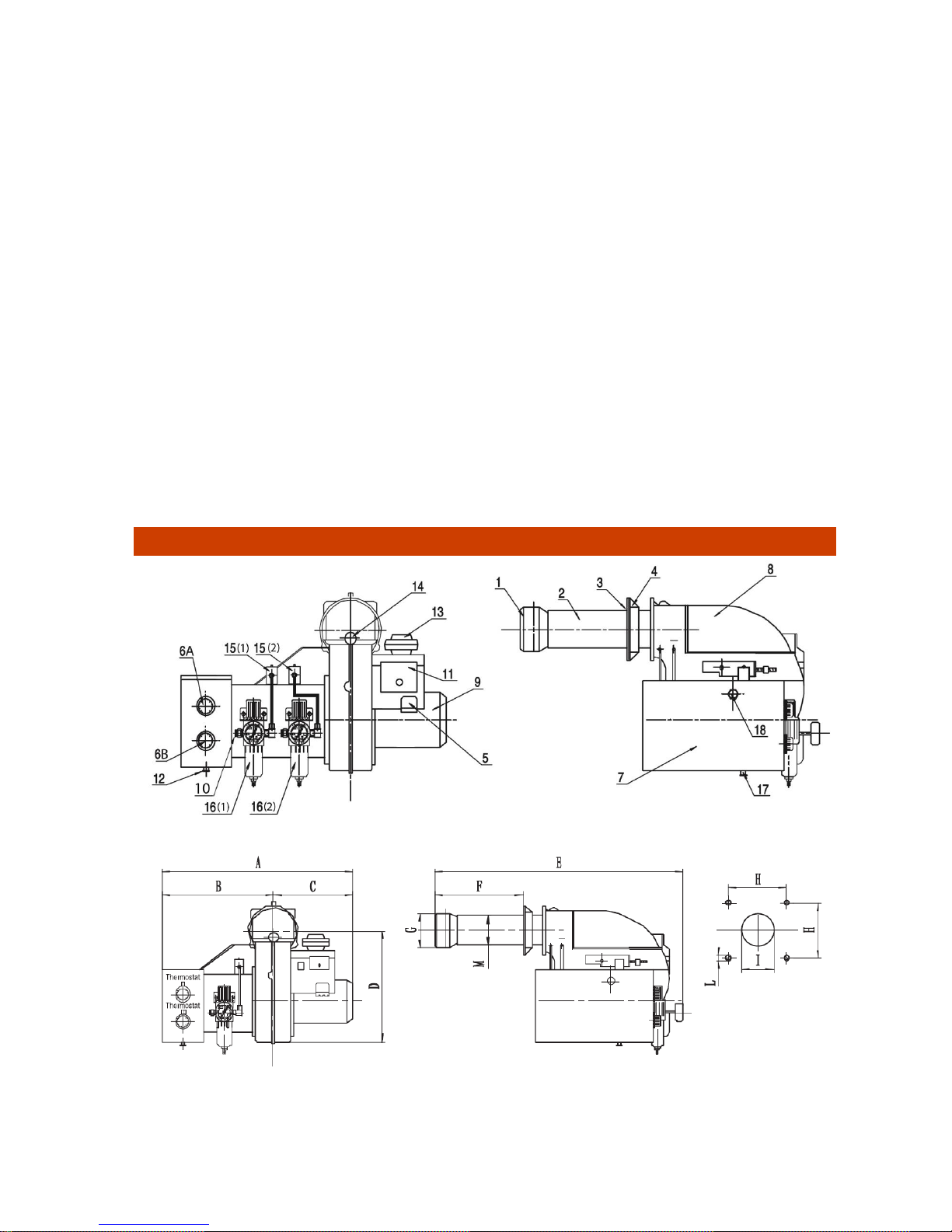
2. Multi-fuel burners NORTEC WB description and features
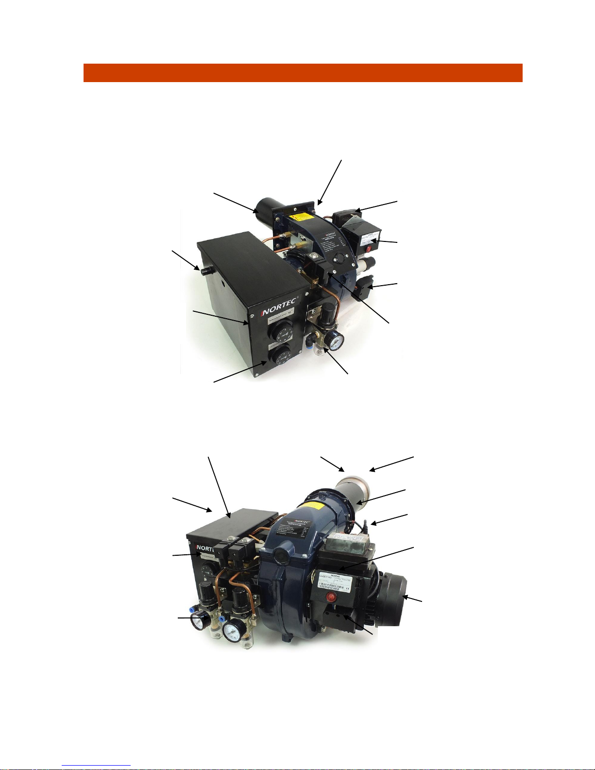
NORTEC WB burners are designed in 2 frames of typical sizes (see section 4).
Models WB60/120 (pic. 1) have one line to connect compressed air and one pressure regulator.
Models WB 230/270 (pic. 2) have two lines to connect compressed air and two pressure
regulators what follows the principle of two-stages start.
Pic. 1 Burners NORTEC WB60 and WB 120
Pic. 2 Burners NORTEC WB230 and WB270
Preliminary fuel
heater
Air regulator with a moisture
separating filter and manometer
Control chamber with an
indicator of emergency
shutdown
Electric socket
Electromagnetic
valve
Ignition transformer
Photocell
Fuel heating
thermostat
Nozzle for
adding fuel
Combustion tube
Fuel heating
thermostats
Preliminary fuel heater
Air regulators with a
moisture separating
filter and manometer
Electromagnetic
valves
Electric socket
Control chamber with an
indicator of emergency
shutdown
Ignition transformer
Photocell
Combustion tube
Diffuser
Fan electric engine
Page 4
4
Technical features of the burners NORTEC WB:
Model
Heat
power
kW
Air
consumption
m3/h
Air
pressure
MPa
Fuel
consumption
kg/h
Power
consumption
kW
(voltage/frequency)
V/Hz
Number and
value of
nozzles
Weigh
t, kg
WB 60
30–59
5
0,15-0,3
3,65–6
1,5 (220/50)
1 / 2.0 –
30о
36
WB 120
55–130
9,5
0,2-0,3
6,03–13
1,5 (220/50)
2 / 2.0 –
30о
37
WB 230
130-230
12
0,2-0,4
14-23
2,6(220/50)
2 / 2.5 –
80о
45
WB 270
190-270
15
0,2-0,4
19-27
2,6(220/50)
3 / 2.5 –
80о
45,5
The sizes of burners – see section 4.
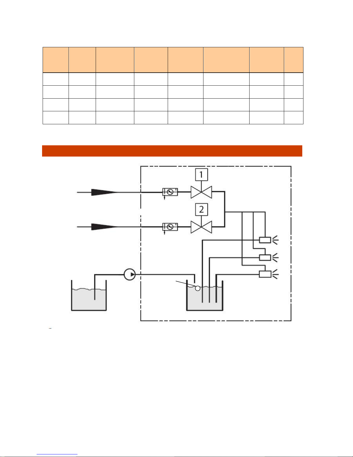
3. Diagram and function of NORTEC WB burners
* *not in the models NORTEC WB60 and WB120
** model NORTEC WB60 has 1 nozzle, WB120 and WB230 have 2 nozzles each and WB 270 - 3 nozzles
1. After getting a signal from the float placed in the preliminary fuel heater box the pump of
the lifting unit starts filling the box. At some point depending on the position of the float a
micro switch goes off which means that the box is full and the pump is off.
2. The thermostats of the preliminary fuel heating box set the maximum and minimum
temperature for heating the fuel.
3. From the thermostats signal the heaters start heating the fuel. At the minimum temperature
of the fuel one of the thermostats switches off and only one heater remains to work.
4. As soon as the given temperature of the oil is reached, the second heater switches off and
the burner gets ready to blow off the chamber of combustion. At this moment the fan of
secondary air works and the primary air valve is closed.
nozzles **
Preliminary fuel
heater
Lifting unit with
a pump and filter
External fuel tank
Compressed air line 1
Solenoid valves
Primary air
regulator 1
fuel
Primary air
Compressed air line 1
Primary air
regulator 2*
float
Page 5
5
5. After the blow-off is finished, the control chamber sends a signal to start ignition and opens
the electromagnetic valve for compressed air line 1. The air goes through the filter
separating moisture that has a pressure regulator and manometer. The amount of
pressure for primary air of line 1 is set within 0.15 - 0.4 MPa.
6. While going through the nozzle primary air causes vacuum on the fuel line and it starts
sucking the heated fuel from the preliminary heater.
7. In the flow of primary air the fuel gets atomized (becomes finely dispersed) and mixes up
with a swirled flow of secondary air.
8. The spark sent to the ignition electrodes inflames air and fuel mix. The photocell marks the
presence of flame, and the ignition process begins.
9. After a while the control chamber sends a signal to open the electromagnetic valve of line
2 (not in NORTEC WB 60/120 burners) and the burner starts working at full power.
10. For models NORTEC WB 60/120 full power of a burner is shown by the amount of primary
air pressure in line 1, and for models NORTEC WB 230/270 it is shown by the amount of
pressure in both inlets.
11. If the fuel level in the preliminary heater gets lower a certain level, the float goes down and
blocks the pump contact. The fuel is added in the heater.
12. If the flame goes out when the fuel runs out because of too high primary air pressure or
due to other reasons, the photocell switches the burner off and the error signal turns on.
Manual restart is needed.
13. If the temperature of the fuel in the heater is lower than it was given on the thermostat, the
burner stops working and heats the fuel up to the given temperature. The restart is
automatic.
4. Design, main elements and sizes of NORTEC WB burners
Pic.3 NORTEC WB burners elements
Pic.4 NORTEC WB burners dimensions
Page 6
6
* Air line 2 is in NORTEC burners WB 230 and WB 270
Dimension and set-up sizes of burners NORTEC WB
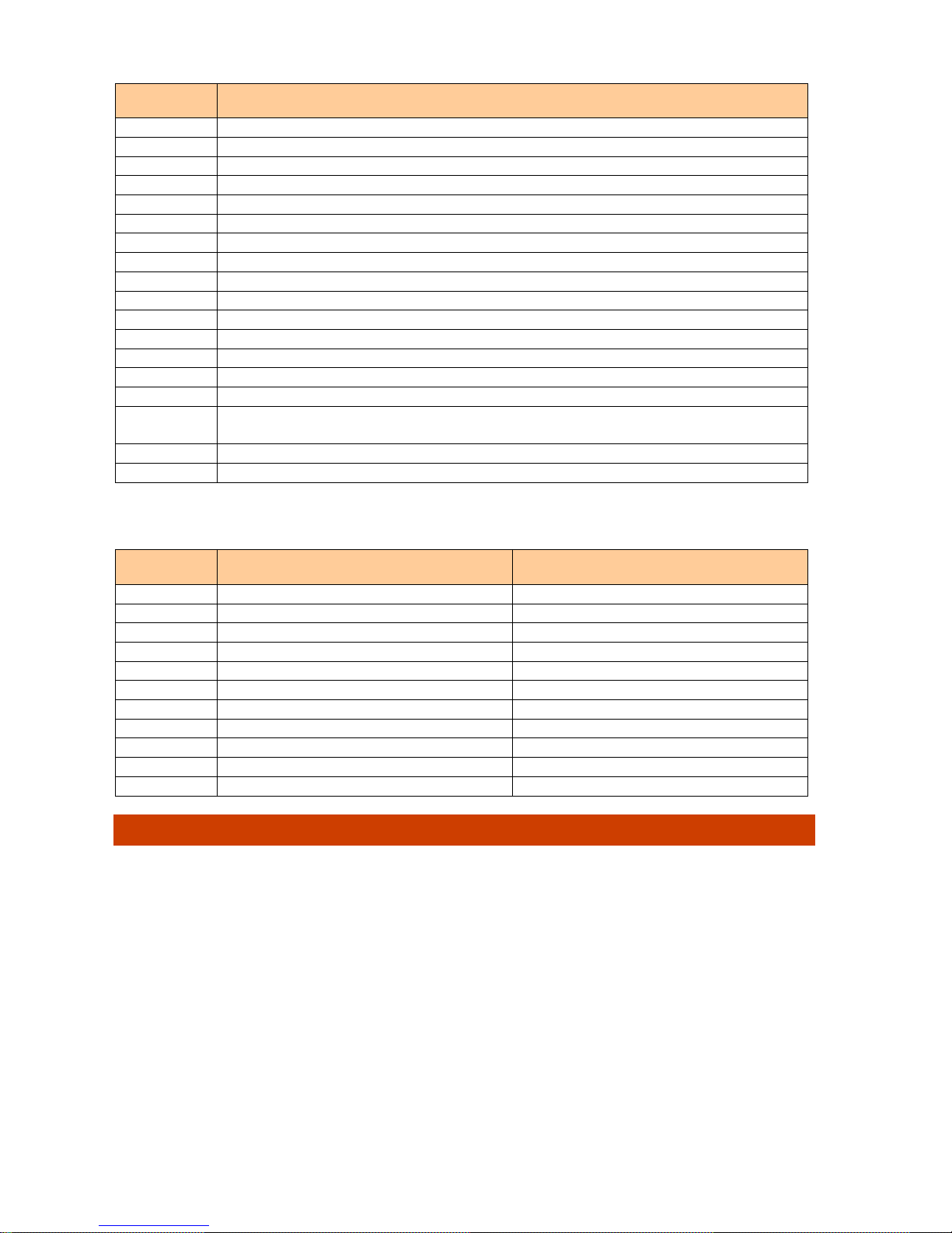
5. Burner head (electrodes and dispenser position) adjustment
Consistent ignition, optimum flame shape and the most efficient combustion depend on correct
adjustment of such elements as dispenser, nozzles, combustion tube and ignition electrodes in
relation to each other.
An incorrect electrode position causes inconsistent ignition or contamination of the electrodes.
An incorrect dispenser position may change the flame shape and burner power, cause drops of
unburnt fuel on the bottom of the combustion chamber.
To adjust the burner head correctly use the diagrams (pic. 5 and pic.6) and the chart showing
distance between the elements.
Before starting the adjustment take the combustion tube off by unscrewing 4 fixing screws that
attach the tube to the burner shell.
Adjustment of the burner with 3 nozzles (WB 270) is similar to the one for the burner with 2
nozzles (WB 230).
#
Element name (pic.1)
1
Diffuser (not used in models WB60 and WB120)
2
Combustion tube
3
Asbestos heatproof pad
4
Installation flange
5
7-pin socket for power and fuel pump connection
6 А, B
Thermostats unit for preliminary fuel heating
7
Preliminary fuel heater
8
Burner shell
9
Fan engine
10
Socket for compressed air connection
11
Control chamber with an indicator of emergency shutdown
12
Drain tap of the preliminary heater
13
Ignition transformer
14
View hole
15 (1),(2)*
Electromagnetic valves (solenoids) 1 and 2* of air lines
16 (1),(2)*
Air filters separating moisture and regulating primary air pressure in lines 1
and 2*
17
Drain tap of the preliminary heater
18
Fuel way inlet
Size
WB60/120, mm (pic. 2)
WB230/270
A
460
530
B
280
300
C
180
230
D
205
212
E
415
540
F
80 – 110
105 – 200
G
95
134
H
93
137
I
105
150 L M8
M8 M 95
114
Page 7
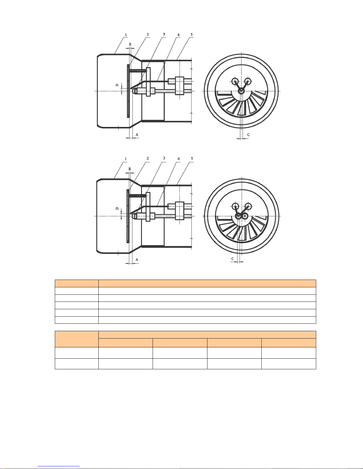
7
Pic. 5 Burner with 1 nozzle
Pic. 6 Burner with 2 and 3 nozzles
#
Element name (pic. 1)
1
Diffuser (not for models WB60 and WB120)
2
Dispenser
3
Nozzle
4
Electrode
5
Combustion tube
Burner
model
Relative distance between elements (mm)
A B C
D
WB 60/120
4-5 1 2-4
5.5-6
WB 230/270
5-6 1 3-5
5-7
A dispenser position affects relation of the volumes of straight air going along the outer edge of
the dispenser and swirled air going through the dispenser blades. If distance A gets bigger, the
volume of straight air grows, fuel mixes with air at lower speed, the flame grows higher and
becomes less consistent. If distance A gets smaller, the flame becomes less intensive, air and
fuel mix at higher speed, the flame gets shorter and wider.
Page 8

8
6. Secondary air shutter adjustment
A secondary air shutter is used to adjust the burner according to back pressure in the
combustion chamber to get maximum fuel combustion. NORTEC WB burners are single-stage
with manual adjustment of the shutter.
To do the adjustment loose screw A (pic. 7) and get the amount of CO2 in waste gas within 1011,5% by adjusting the air shutter, then tighten screw A.
Pic.7 Secondary air shutter
7. Burner power (primary air pressure) adjustment
Pic. 8 Primary air control with air filter
Inlet connector for
compressed air
Manometer
Drain filter valve
Air inlet
Pressure regulator cap
Page 9

9
Burner power is regulated by changing primary air pressure.
To maintain combustion primary air pressure in inlet 1 with open electromagnetic valve has to
be more than 0.15 MPa and less than 0.3 MPa.
This value is set on the regulator for a burner with one air line (NORTEC WB60/120) and on a
regulator of line 1 (left manometer) for burners with two air lines (NORTEC WB230/270).
To adjust primary air pressure pull the pressure regulator cap up and rotate it to increase or
decrease the pressure.
To increase pressure rotate the regulator cap clockwise, to decrease it rotate the cap counter-
clockwise.
After adjustment press the cap lightly to get it back to its start position.
The set pressure is reflected on the manometer of each regulator.
The pressure in the second line of burners NORTEC WB 230/270 can be more than 0.4 MPa
and is chosen according to the allowed boiler power.
NB! Sometimes the manometer shows the set pressure value with a closed
electromagnetic valve, but after it is open, the pressure falls abruptly. It’s important to
get the set pressure value by rotating the cap when the valve is open.
In case of condensed vapor in the drying filter box, pour it out by pressing the drain valve head.
8. Preliminary fuel heating temperature
Consistent fuel combustion are provided with fine spray and ignition. For this reason, the fuel is
heated in the preliminary heating chamber where fuel viscosity is lowered.
The preliminary heating chamber has two heaters each of which is controlled by its own
thermostat.
Thermostats knobs are placed on the front board of the heater (pic. 9).
Pic. 9. Regulating thermostats
Thermostat 1
Thermostat 2
Page 10

10
Thermostat 1 (top thermostat) controls switching on and off the burner automatic system. It
must set on 0 if diesel or kerosene are used and in case of other fuel types it must be set on the
temperature indicated in the chart below:
Fuel type
Thermostat 1
temperature, оС
Thermostat 2
temperature, оС
Diesel 0 0
Kerosene 0 0
Waste motor oil
70
75-80
Waste transmission oil
75
80-85
Vegetable oil
100
105-110
After the burner is turned on, both heaters get switched on and fuel heating begins. As soon as
the fuel is heated up to the temperature set on the thermostat 1, the burner control chamber
starts working and the ignition begins, then the heater 1 switches off. The heater 2 is on to keep
the fuel temperature up to its working value.
NB! Fuel characteristics may differ a lot. Generally, starting the burner first time set
thermostat 2 on its maximum temperature at which fuel doesn’t start boiling yet. Set
thermostat 1 5-10 grades lower than thermostat 2
9. Photocell, fault indicator and controller
Photocell is a flame-monitoring device. If the burner hasn’t started up or the flame has gone out
suddenly, the photocell sends a signal for emergency shutdown of the burner. In 10 seconds
after the photocell discovers flame absence, the burner will be shut down and the emergency
indicator will be switched on the control chamber.
NB! If the photocell is exposed to intense room light that gets inside the burner
through the view hole, the burner may stop working correctly. Keep the view hole
away from intense light source.
Emergency shutdown indicator is placed on the control chamber surface and it looks like a
rubber red button. In case of emergency the control chamber switches off the burner and the
emergency light turns on inside the indicator.
NB! In case of emergency shutdown the burner’s work can be resumed only after a
complete fix of the emergency situation. Then the burner can be manually restarted.
To restart the burner manually press the emergency indicator button until it clicks. The indicator
will switch off and the burner will start up again. If necessary an emergency signal (lamp or ring)
can be connected to inlet T1 as it is shown on the diagram of burner electrical wiring (see
below).
NB! To prevent premature manual restart the control chamber has a restart delay for
3 minutes after emergency shutdown.
Control chamber Siemens LOA24.171B27 is placed on the right above the burner electric
engine. It controls safety and consistency of the burner work in automatic mode. The control
chamber has the following work periods:
Emergency shutdown delay,
sec.
Blow-off, sec.
Ignition, sec.
Period before flame
control start, sec.
10
13
15
15
Page 11

11
10. Electric wiring diagram
NB! Installation, connection and adjustment works on burners NORTEC WB must be carried
out only by qualified staff having a pass to electric installation, experience in service and
installation of these burner types and authorized by the producer or official distributer of
NORTEC equipment.
Pic. 10 Electric diagram of burners NORTEC WB 60/120
Н3
To the pump of a
lifting unit
Burner socket
Page 12

12
Pic.11 Electric diagram of burners NORTEC WB 230/270
Electric diagram symbols:
K1: Heater №1
K2: Heater №2
K3: Heating elements of fuel inlets
H1: Thermostat №1
H2: Thermostat №2
H3: Floating switch of a fuel pump
LOA24: Control chamber of the burner
TA: Ignition transformer
V1: electromagnetic valve of air inlet 1
V2: electromagnetic valve of air inlet 2
M: burner fan engine
FR: photocell
HL: external emergency shutdown signal
F: cutout (16A)
TC: boiler thermostat
TS: safety thermostat
Electric diagrams of NORTEC burners WB 230 / 270 have an electromagnetic valve for
compressed air inlet 2.
To the pump of a
lifting unit
Н3
Burner socket
Page 13

13
11. Lifting unit
A lifting unit (pic. 12) has a gear pump with its own electric engine, a flange to connect fine fuel
filter and a set of flexible tubes one of which has a sieving fuel inlet on the end.
Pic. 12 Lifting unit with a fine fuel filter
Instead of a fine fuel filter any car oil filter with standard rim diameter and screw can be used.
Cargo vehicle filters are more long-lasting because of their large volume.
Before installing an oil filter fill it with fuel and put some on a rubber o-ring. Assembling and
dismantling the filter should be done with a catch hook that can be bought in a car parts shop.
The lifting unit has to be installed on the main fuel box, if it is placed in the room next to the
burner, or on the waste fuel box next to it, if the main box is not placed in the room. In the latter
case the fuel flow from the main box to the waste one has to be organized.
Electric connection of the lifting unit is done according to the burner electric diagram (pic.10 and
11)
The base box of the lifting unit must be grounded!
NB! To keep fuel clean, a sieving fuel inlet needs to be installed so that its lowest part
was no less than 15-20 cm from the bottom of the fuel box. It will prevent water and
solid dregs from getting into the burner.
It is better to have a floating fuel inlet. For this purpose, any suitable float (sanitary or an empty
plastic bottle) can be adjusted to it. It is recommended to use a limiting chain or wire which will
not let the fuel inlet to go down to the bottom of the box. (pic. 13)
Electric engine
Gear fuel pump
Fuel filter flange
To the fuel box
(via flexible tube
with a fuel inlet)
To the burner
(via blue flexible tube)
Base box
Page 14

14
So, the fuel intake will mostly happen from the top, cleanest layers and, thus, service intervals
for the burner will increase a lot.
It is recommended to do the cleaning and service of the fuel box to get rid of solid dregs and
moisture concentrating on the bottom of the box at least once a month.
That is why, while installing the fuel box, one of its walls needs to be inclined and a drain tap
adjusted to its lowest part.
Pic.13 Floating fuel inlet diagram
NB! Service intervals and the burner lifetime directly depend on the purity of the fuel.
It is recommended to filter the fuel before pouring it into the fuel box, settle the
vegetable oil in cold environment at least for 1-2 weeks before use. Change the
filtering element of the lifting unit at least once a month.
12. Installation of the burner and fuel system
Install the burner on the furnace of a boiler or heat generator using a set-up flange 4 and an
asbestos pad 3 (pic. 4).
To do that:
1. Loose the flange screw so that the burner combustion tube 2 could move easily in the
flange hole. Draw the flange beaks apart with a big screwdriver, if needed.
2. For burners WB230 and WB270, dismantle diffuser 1 by unscrewing three locking screws.
3. Put the flange on the combustion tube with its flat part to the furnace and adjust it on the
combustion tube. Length of the combustion tube sticking out into the combustion chamber
is indicated in the manual for your boiler (heat generator). Calculating a place for the
flange take the thickness of pad 3 and the length of diffuser 1 into account. (pic. 4).
4. Tighten the flange screw so that the burner had a horizontal position after installation.
Don’t tighten too much to avoid breaking the flange.
5. Put on a pad and diffuser, tighten the locking screws of the diffuser.
to the pump
Float
fuel
dregs and
moisture
sieving fuel inlet
limiting chain
Fuel tank
Page 15

15
6. Connect the burner and the furnace and fasten the flange with four screws. Tighten the
flange screws diagonally so the pad was pressed to the furnace evenly. Don’t allow the
flange inclination error!
After installing the burner, install the lifting unit on the fuel box. (pic. 12).
Adjust a fuel inlet in the fuel box as it is shown on pic. 13 and connect the flexible tube of the
fuel inlet with the pump nozzle.
Set the nozzle in the hole 18 (pic.4) of the burner preliminary heating box.
The nozzle is an angle brass unit with carving and a pad. It is screwed onto a blue flexible tube.
Disconnect the nozzle from the flexible tube and put its carving part with a pad inside the box
into the hole 18 so that the outlet hole of the nozzle looked down. Put a nut of the blue flexible
tube on the carving from the outside and tighten until the connection is stationary and leakproof.
NB! The nozzle hole must look down for safe fuel entry.
Connect the end of the blue flexible tube to the pump nozzle (pic.13).
Install the filtering element from the kit on the flange of the lifting unit (pic.13)
For that, first fill the element with fuel and put some fuel on a rubber ring pad to make the
connection leak-proof.
NB! Further on it is possible to use any suitable car oil filter as a filtering element.
Using cargo vehicle filters will increase service intervals and help the pump work
thanks to their big volume and large surface of the filtering element.
Connect an oil-resistant flexible tube to the nozzle for fuel flow (pic.1) and return it to the main
fuel box or a metal box with at least 5-liter volume in case of accidental overflow of heated fuel
from the heater box. So you will keep your room tidy and avoid losing the fuel.
NB! The main fuel box must NOT be higher the drain nozzle of the preliminary
heating box (pic.1). Otherwise the fuel will get into the heater uncontrollably and
cause fuel overflow what may lead to a fire hazard situation.
If the fuel box is below the burner, set up an electromagnetic locking valve on the fuel-supply
line by connecting it into a gap of the power-supply circuit of the fuel pump.
Examples of correct and incorrect installation of the fuel box in relation to the burner can be
found on pic. 14:
Page 16

16
Pic. 14 Examples of installation of the fuel box in relation to the burner
13. Electrical connection of the burner
ATTENTION!
Works on electrical connection and start-up of the burner must be carried out only by competent
staff who are allowed to work on electrical connection, have experience in burners installation
and are authorized by the producer or an official distributor of NORTEC products!
Electricity must be switched off before the works start!
Ignoring safety rules may cause emergency!
Damage caused by incompetent installation can not be covered by warranty!
CORRECT
INCORRECT!
INCORRECT!
Fuel tank
Fuel pump
Preliminary heater
Page 17

17
1. Switch off the electricity on the supply line.
2. Connect the cable of the lifting unit pump to suitable inlets of the burner outer part. (pic. 10,
11).
3. Connect the outer security thermostat and the heater thermostat into a gap of the power-
supply chain as it is shown on pic.10, 11.
4. Connect the grounding of the lifting unit and burner.
5. Connect the power-supply chain to the burner outer part according to the pictures 10, 11.
6. Check all the connections, tighten the locking screws and check isolation.
14. Burner start-up
Add 3-3.5 litres of fuel into the preliminary fuel heater box so the fuel fills up to ⅔ of the box.
Connect air lines of the compressor. Make sure output pressure of the compressor is at least 4
atm and the compressor capacity is enough for this burner model.
Open the compressor tap and set all the necessary values for air pressure in lines 1 and 2 (see
section 7). For consistent ignition keep the pressure in lines 1 and 2 at 0.2-0.3 MPa.
NB! In some cases when the electromagnetic valve is closed, the manometer shows
the set pressure value, but after the valve gets open, the pressure falls immediately.
Turning the regulator cap get the pressure value back with the electromagnetic valve
open.
Set the temperature in the preliminary fuel heater using thermostats 1 and 2 (6A and 6B on pic.
3) as it is shown in section 8.
Connect the outer burner part to the relevant part on the burner base.
The burner will start working according to the scheme described in section 3.
15. Regulating burner work
Due to back pressure from the combustion chamber of the boiler (heat generator) the burner
power and secondary air volume may need to be regulated.
The burner power depends on the volume of primary air, hence on pressure set on the
regulators 16(1) and 16(2) (pic. 3).
Setting the burner power at the first stage keep the consistency of ignition. Don’t increase the
value more than 0.3 MPa to avoid losing the flame.
At the second stage (for burners WB 230 and WB 270) the pressure can reach 0.4 MPa and
depends on the consistency of this burner work at full power with this boiler model.
Current burner power is defined by fuel consumption which is approximately 1 kg of fuel for 10
kW of burner power at rated operation conditions.
So, if you know the fuel consumption per hour, you can define burner power in this boiler with
this fuel.
It is impossible to define exact burner power value because of different heat capacity of fuel
types used for these burners.
Page 18

18
NB! Burner power must NOT be more than rated combustion chamber power. Set
the burner power at about 80% from the rated boiler power. Otherwise, there may be
burnout of the combustion chamber.
The amount of secondary air is regulated by changing the position of the secondary air shutter
(pic.7) as it is described in section 6.
Work diagrams for the burners are shown on pic. 15.
Pic. 15 Work diagrams of burners NORTEC WB
16. Main troubles and their solving methods
Troubles in this section are caused by ignoring the information in this guide or other reasons not
connected with equipment faults.
In case of an equipment fault trouble we recommend you to call an authorized NORTEC service
center or the place where the equipment was purchased to consult a specialist.
NB! Non-authorized repair works make your warranty on NORTEC equipment
invalid!
Restart the burner after trouble shooting by pressing the red button of the emergency shutdown
indicator (section 9).
kg/h
mBar
3 6 13
23
27
4
3
2
1
WB60
WB120
WB230
WB270
Page 19

19
Trouble
Possible reason
Solving method
Burner does not start after
start-up or works
inconsistently giving out an
error
Primary air pressure in line 1
is set beyond recommended
value.
Regulate primary air pressure value according to
section 7.
Fuel does not heat up to
necessary temperature.
Increase fuel heating temperature value according
to section 8.
There is too much moisture in
the fuel.
Let the fuel stand before use. Adjust the floating fuel
inlet according to section 11.
There are mud or solid dregs
in the fuel.
Replace the filtering element according to section
11. Clean the fuel box, let the fuel stand and adjust
the floating fuel inlet according to section 11.
There is too much synthetic
oil in the fuel.
Add some mineral oil into the fuel. It should be 30%
fuel, 70% mineral oil.
or
Add 10-20% of diesel to the fuel volume.
Fuel does not ignite properly.
Check the fuel. Replace it or add diesel. Combine
proportion experimentally.
Littered sieving filter in the
preliminary fuel heating box.
Clean the filter. Replace the filtering element of the
lifting unit. Clean the heater box from dregs and
soot.
Moisture in the preliminary
heating box.
Pour moisture out via drain tap 17 (pic.3). Adjust a
floating fuel inlet according to section 11.
Littered nozzles.
Use an authorized service center NORTEC to clean
the nozzles.
Clean the fuel system thoroughly, replace a filtering
element of the lifting unit.
Fuel does is not delivered to
the preliminary heater box
Lifting unit pump is not
connected.
Check the connection and connect the pump
according to section 13.
No fuel in the main fuel box.
Add fuel to the box.
Littered fuel inlet.
Clean the fuel inlet, clean the fuel box from dregs
and moisture, set the floating fuel inlet according to
section 11.
Fine cleaning filter is
exhausted.
Replace the filtering element according to section
11.
Fuel tube is pinched.
Remove the pinch.
The float is hung up in the
heater box.
Release and work on the float. Clean the box from
dregs and resin.
The lifting unit and burner are
too far from each other.
Move the fuel box closer to the burner or set up
another box next to the burner. Make the fuel line
cross section bigger.
Fuel flows out via the drain
hole of the heater box
Fuel is heated up too much.
Turn down the temperature of fuel heating
according to section 8.
Page 20

20
The float is hung up in the
heater box.
Release and work on the float. Clean the box from
dregs and resin.
Compressed air is not
delivered to the burner or its
pressure is not enough
The compressor is switched
off.
Switch the compressor on.
The compressor does not
comply with the burner by its
capacity.
Replace the compressor based on the information in
section 2.
Pressure set on the
compressor is too low.
Set the pressure on the compressor within 4-5 atm.
Air tube is pinched or broken.
Check the air connection and solve the trouble.
Condensed water in filters,
settlers of regulators 16
(pic. 3).
Press the drain valve and pour condensed water
out. If necessary, turn the glass cap of the settler off
and clean the sieving filter
The burner power is lower
than indicated
Incorrect burner adjustment in
the combustion chamber.
Regulate the combustion tube position according to
the guide on the boiler or heat generator.
Incorrect regulation of
secondary air use.
Regulate the shutter position according to section
15 or call a specialist from NORTEC service center
to do the adjustment.
Low primary air pressure in
lines 1 and 2.
Regulate primary air parameters according to
section 15 call a specialist from NORTEC service
center to do the adjustment.
To consult a NORTEC representative, please, call: 8 (495) 223 27 03
17. Service and warranty
You have purchased reliable long-life equipment from NORTEC.
For long and smooth use of NORTEC WB burners follow service intervals, regularly monitor the
burner and fuel systems, timely replace the filtering element of the lifting unit and clean the
preliminary heater, fuel inlet, nozzle unit from dregs, soot and mechanical dirt.
Do not allow dregs and moisture to accumulate in the fuel box, timely pour condensed water out
of the fuel box, the preliminary heater box and moisture separating filter of the air line.
Cleaning intervals depend on fuel quality and purity. Normally, a service interval is 1-2 weeks, if
waste oils are used.
NB! Do not use the burner without cleaning for a long time as it will cause difficult-toremove dregs on heating elements, float, nozzles and sparger.
To clean the preliminary heater box use a detergent. To remove dregs and soot from nozzles
and sparger use acetone.
To clean the sparger and nozzles take the burner off the furnace without changing the flange
position on the combustion tube.
Page 21

21
NB! In case of heavy contamination in the nozzles unit which requires dismantling of
the burner, call a specialist in an authorized NORTEC service center.
Call a specialist from an authorized NORTEC service center at least twice a year to maintain
smooth work of the burner.
Warranty period of NORTEC WB burner is established by the Russian Federation law as
12 months since the purchase of a burner from an authorized NORTEC distributor.
Equipment is repaired under warranty after a buyer shows a filled warranty certificate for the
burner with a stamp of the distributor and a receipt (invoice) with the date of purchase.
Warranty turns invalid in the following cases:
1. Use and service conditions are different from the indicated in the guide.
2. Using inflammable substances such as gas, spirit, ester, acetone etc. as fuel. The producer is
not responsible for an outcome of such substances use in NORTEC burners.
3. Mechanical damage of the burner or pump.
4. Non-authorized dismantling, construction change or repairing of the burner.
5. No documents confirming the fact of purchase from an authorized distributor.
18. Supply package
NORTEC WB burner supply package consists of:
#
Name
Amount, pcs
1
NORTEC WB burner assembled
1
2
Set-up flange
1
3
Asbestos flange pad
1
4
Lifting unit assembled
1
5
Fuel tube
2
6
Sieving fuel inlet
1
7
Rubber pad for fuel receiving nozzle
1
8
Fuel receiving nozzle
1
9
Fine cleaning fuel filter
1
10
7-pin plug of a burner, outer part with a pump wire
1
11
Box lid of preliminary fuel heater
1
12
Fix screws with disks and nuts
4
13
User guide
1
Page 22

22
19. Vendor details and copyright
Exclusive NORTEC equipment distributor on the territory of Russia and CIS is LLC “TK-Service”
INN 7719573483
Address: 123007, Moscow, 2nd Magistralniy dead-end street, bld. 7a
Phone: +7 (495) 223 27 03
Web: www.nortec.pro
Email: info@nortec.pro
All rights on using trademark on the Russian Federation territory belong to LLC
“TK-Service”.
Copyright rights on this User Guide belong to NORTEC® trademark owner. Full or partial use of
this Guide materials without the knowledge of the owner is prohibited and prosecuted by
Russian law on copyright protection.
Due to constant upgrade of NORTEC®, equipment, its characteristics, construction details and
appearance may be different from those described in this Guide.
Page 23

Index
№
Chapter
Page
1
Multi-fuel burners NORTEC WB features
2
2
Multi-fuel burners NORTEC WB description and features
3
3
Diagram and function of NORTEC WB burners
4
4
Design, main elements and sizes of NORTEC WB burners
5
5
Burner head (electrodes and dispenser position) adjustment
6
6
Secondary air shutter adjustment
8
7
Burner power (primary air pressure) adjustment
8
8
Preliminary fuel heating temperature
9
9
Photocell, fault indicator and controller
10
10
Electric wiring diagram
11
11
Lifting unit
13
12
Installation of the burner and fuel system
14
13
Electrical connection of the burner
16
14
Burner start-up
17
15
Regulating burner work
17
16
Main troubles and their solving methods
18
17
Service and warranty
20
18
Supply package
21
19
Vendor details and copyright
22
Stamp of a seller and selling date:
« » ________________ 201 г.
 Loading...