

Nortec WB60, WB230, WB120, WB270 Installation Manual
Multi-fuel oil burners
NORTEC WB
Installation manual
Models WB60, WB120, WB230, WB270
www.nortec.pro
2013
2
Read carefully the Guide before installing and using the burner
Nortec WB!
Installation and start works have to be carried out only by specialists.
Power supply must be switched off before the works start!
Neglecting safety rules can cause an accident.
Dear customer!
Thank you for purchasing NORTEC products. We do everything to make sure you use
NORTEC equipment effectively for a long time!
1. Multi-fuel burners NORTEC WB features
NORTEC WB burners use waste engine and transmission oil, kerosene, diesel oil, light fuel oil,
liquid animal and vegetable oil.
Don’t use as fuel:
flammable liquids such as gas, ester, acetone, spirit etc.
The burners combine the functions of fuel supply, heating, spray and air supply, ignition and
flame supervision, so achieving automatic control of the combustion process.
Thanks to their robust and high-quality design NORTEC burners have the following features:
1. Well-automated fuel supply.
NORTEC burners are low pressure burners and compressed air supply with the pressure
from 0.15 to 0.4-0.5 MPa is required for good fuel spray.
2. Optimum mix of air and fuel, stable flame and efficient combustion.
The burners use air swirl technology with a sparger that provides fine and even mix of
sprayed fuel and secondary air, stable, complete and economic combustion.
3. Safe, reliable, automatic control.
NORTEC burners are equipped with an advanced control and safety system from Siemens.
It stops fuel supply and combustion process in case of emergency. Automatic control of fuel
temperature, fuel level in the chamber of preliminary heating, ignition and flame, the system
of automatic shutdown and restart make NORTEC WB burner easy and safe to use.
4. Flexible installation.
Each burner is equipped with long combustion tube and sliding flange that allows to use the
burner with any boiler and heat generator.
5. Easy maintenance.
The burners are easy to dismantle for regular cleaning and service.
3
2. Multi-fuel burners NORTEC WB description and features
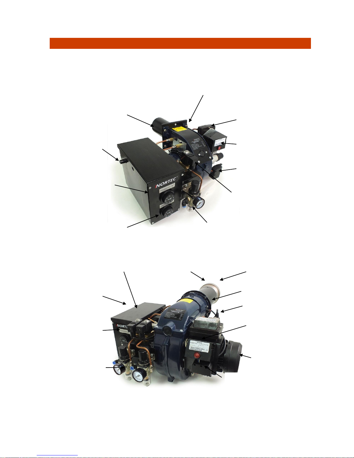
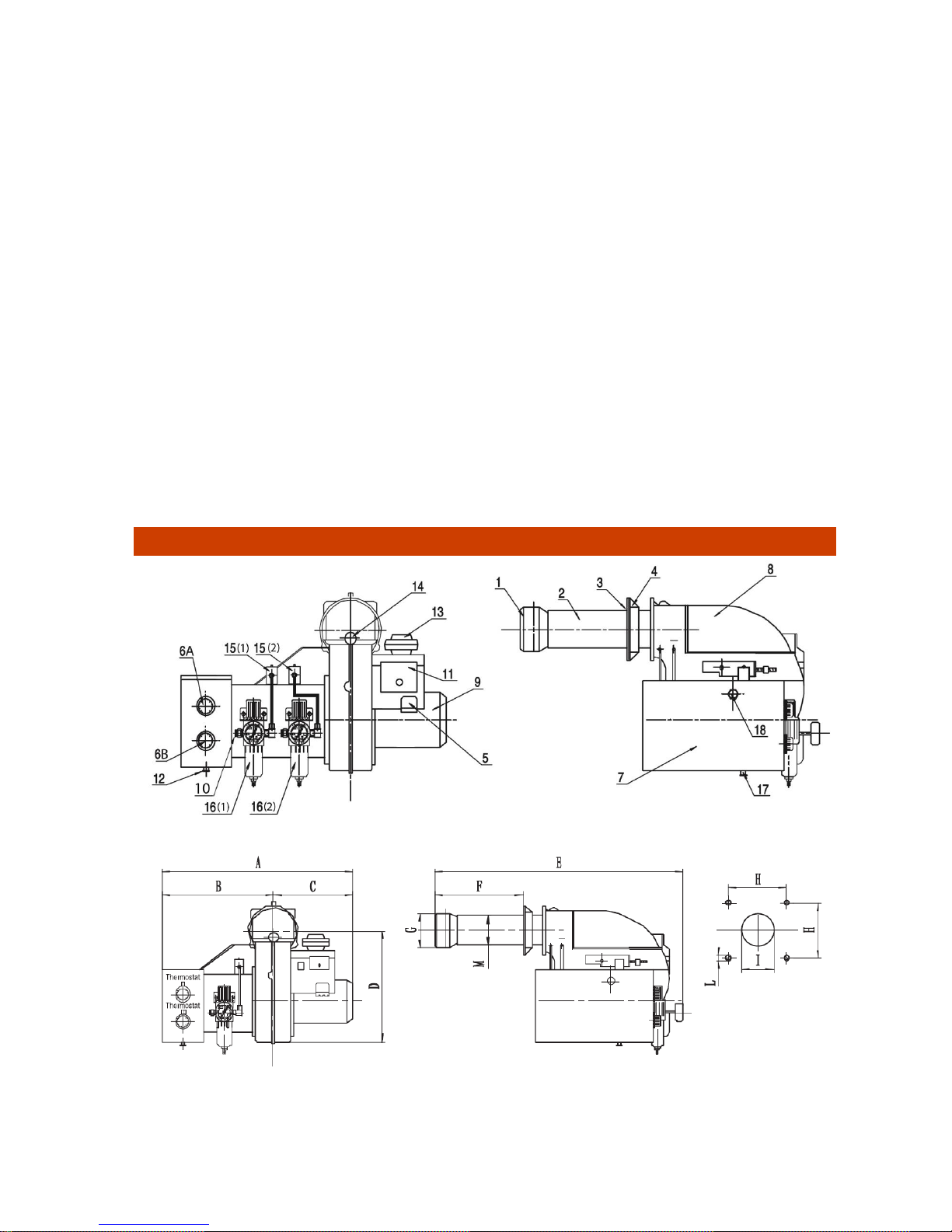
NORTEC WB burners are designed in 2 frames of typical sizes (see section 4).
Models WB60/120 (pic. 1) have one line to connect compressed air and one pressure regulator.
Models WB 230/270 (pic. 2) have two lines to connect compressed air and two pressure
regulators what follows the principle of two-stages start.
Pic. 1 Burners NORTEC WB60 and WB 120
Pic. 2 Burners NORTEC WB230 and WB270
Preliminary fuel
heater
Air regulator with a moisture
separating filter and manometer
Control chamber with an
indicator of emergency
shutdown
Electric socket
Electromagnetic
valve
Ignition transformer
Photocell
Fuel heating
thermostat
Nozzle for
adding fuel
Combustion tube
Fuel heating
thermostats
Preliminary fuel heater
Air regulators with a
moisture separating
filter and manometer
Electromagnetic
valves
Electric socket
Control chamber with an
indicator of emergency
shutdown
Ignition transformer
Photocell
Combustion tube
Diffuser
Fan electric engine
4
Technical features of the burners NORTEC WB:
Model
Heat
power
kW
Air
consumption
m3/h
Air
pressure
MPa
Fuel
consumption
kg/h
Power
consumption
kW
(voltage/frequency)
V/Hz
Number and
value of
nozzles
Weigh
t, kg
WB 60
30–59
5
0,15-0,3
3,65–6
1,5 (220/50)
1 / 2.0 –
30о
36
WB 120
55–130
9,5
0,2-0,3
6,03–13
1,5 (220/50)
2 / 2.0 –
30о
37
WB 230
130-230
12
0,2-0,4
14-23
2,6(220/50)
2 / 2.5 –
80о
45
WB 270
190-270
15
0,2-0,4
19-27
2,6(220/50)
3 / 2.5 –
80о
45,5
The sizes of burners – see section 4.
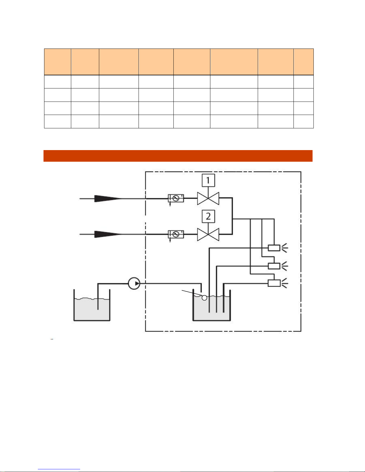
3. Diagram and function of NORTEC WB burners
* *not in the models NORTEC WB60 and WB120
** model NORTEC WB60 has 1 nozzle, WB120 and WB230 have 2 nozzles each and WB 270 - 3 nozzles
1. After getting a signal from the float placed in the preliminary fuel heater box the pump of
the lifting unit starts filling the box. At some point depending on the position of the float a
micro switch goes off which means that the box is full and the pump is off.
2. The thermostats of the preliminary fuel heating box set the maximum and minimum
temperature for heating the fuel.
3. From the thermostats signal the heaters start heating the fuel. At the minimum temperature
of the fuel one of the thermostats switches off and only one heater remains to work.
4. As soon as the given temperature of the oil is reached, the second heater switches off and
the burner gets ready to blow off the chamber of combustion. At this moment the fan of
secondary air works and the primary air valve is closed.
nozzles **
Preliminary fuel
heater
Lifting unit with
a pump and filter
External fuel tank
Compressed air line 1
Solenoid valves
Primary air
regulator 1
fuel
Primary air
Compressed air line 1
Primary air
regulator 2*
float
5
5. After the blow-off is finished, the control chamber sends a signal to start ignition and opens
the electromagnetic valve for compressed air line 1. The air goes through the filter
separating moisture that has a pressure regulator and manometer. The amount of
pressure for primary air of line 1 is set within 0.15 - 0.4 MPa.
6. While going through the nozzle primary air causes vacuum on the fuel line and it starts
sucking the heated fuel from the preliminary heater.
7. In the flow of primary air the fuel gets atomized (becomes finely dispersed) and mixes up
with a swirled flow of secondary air.
8. The spark sent to the ignition electrodes inflames air and fuel mix. The photocell marks the
presence of flame, and the ignition process begins.
9. After a while the control chamber sends a signal to open the electromagnetic valve of line
2 (not in NORTEC WB 60/120 burners) and the burner starts working at full power.
10. For models NORTEC WB 60/120 full power of a burner is shown by the amount of primary
air pressure in line 1, and for models NORTEC WB 230/270 it is shown by the amount of
pressure in both inlets.
11. If the fuel level in the preliminary heater gets lower a certain level, the float goes down and
blocks the pump contact. The fuel is added in the heater.
12. If the flame goes out when the fuel runs out because of too high primary air pressure or
due to other reasons, the photocell switches the burner off and the error signal turns on.
Manual restart is needed.
13. If the temperature of the fuel in the heater is lower than it was given on the thermostat, the
burner stops working and heats the fuel up to the given temperature. The restart is
automatic.
4. Design, main elements and sizes of NORTEC WB burners
Pic.3 NORTEC WB burners elements
Pic.4 NORTEC WB burners dimensions
6
* Air line 2 is in NORTEC burners WB 230 and WB 270
Dimension and set-up sizes of burners NORTEC WB
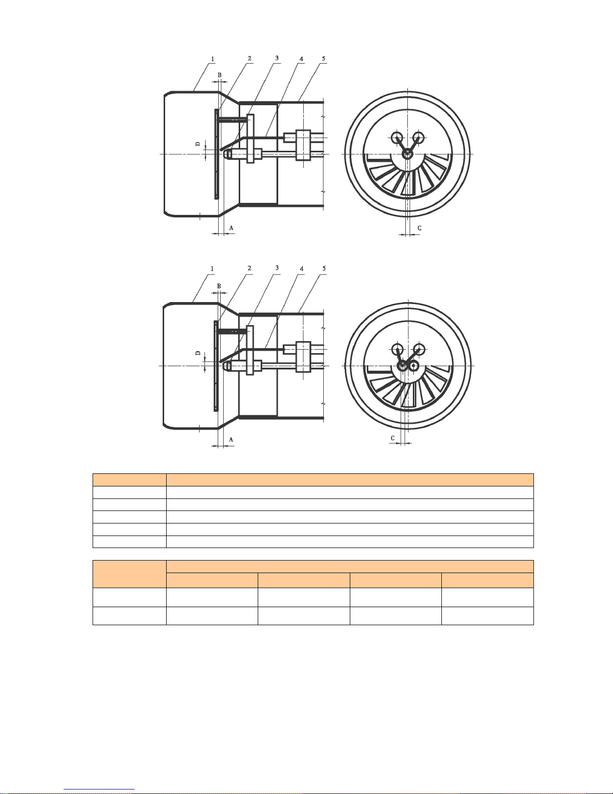
5. Burner head (electrodes and dispenser position) adjustment
Consistent ignition, optimum flame shape and the most efficient combustion depend on correct
adjustment of such elements as dispenser, nozzles, combustion tube and ignition electrodes in
relation to each other.
An incorrect electrode position causes inconsistent ignition or contamination of the electrodes.
An incorrect dispenser position may change the flame shape and burner power, cause drops of
unburnt fuel on the bottom of the combustion chamber.
To adjust the burner head correctly use the diagrams (pic. 5 and pic.6) and the chart showing
distance between the elements.
Before starting the adjustment take the combustion tube off by unscrewing 4 fixing screws that
attach the tube to the burner shell.
Adjustment of the burner with 3 nozzles (WB 270) is similar to the one for the burner with 2
nozzles (WB 230).
#
Element name (pic.1)
1
Diffuser (not used in models WB60 and WB120)
2
Combustion tube
3
Asbestos heatproof pad
4
Installation flange
5
7-pin socket for power and fuel pump connection
6 А, B
Thermostats unit for preliminary fuel heating
7
Preliminary fuel heater
8
Burner shell
9
Fan engine
10
Socket for compressed air connection
11
Control chamber with an indicator of emergency shutdown
12
Drain tap of the preliminary heater
13
Ignition transformer
14
View hole
15 (1),(2)*
Electromagnetic valves (solenoids) 1 and 2* of air lines
16 (1),(2)*
Air filters separating moisture and regulating primary air pressure in lines 1
and 2*
17
Drain tap of the preliminary heater
18
Fuel way inlet
Size
WB60/120, mm (pic. 2)
WB230/270
A
460
530
B
280
300
C
180
230
D
205
212
E
415
540
F
80 – 110
105 – 200
G
95
134
H
93
137
I
105
150 L M8
M8 M 95
114
7
Pic. 5 Burner with 1 nozzle
Pic. 6 Burner with 2 and 3 nozzles
#
Element name (pic. 1)
1
Diffuser (not for models WB60 and WB120)
2
Dispenser
3
Nozzle
4
Electrode
5
Combustion tube
Burner
model
Relative distance between elements (mm)
A B C
D
WB 60/120
4-5 1 2-4
5.5-6
WB 230/270
5-6 1 3-5
5-7
A dispenser position affects relation of the volumes of straight air going along the outer edge of
the dispenser and swirled air going through the dispenser blades. If distance A gets bigger, the
volume of straight air grows, fuel mixes with air at lower speed, the flame grows higher and
becomes less consistent. If distance A gets smaller, the flame becomes less intensive, air and
fuel mix at higher speed, the flame gets shorter and wider.
 Loading...