

Page 1
MH
TM
Series
EVAPORATIVE
HUMIDIFIER/COOLER
Inst allation Manual
2544832-A
Page 2
PROPRIETARY NOTICE
This document and the information disclosed herein are proprietary data of
WALTER MEIER LTD. Neither this document nor the information contained herein
shall be reproduced used, or disclosed to others without the written authorization of
WALTER MEIER LTD., except to the extent required for inst allation or maintenance
of recipient’s equipment. All references to the NORTEC name should be taken as
referring to WALTER MEIER LTD.
LIABILITY NOTICE
WALTER MEIER LTD. does not accept any liability for installations of humidity equipment installed
by unqualified personnel or the use of parts/components/equipment that are not authorized or
approved by WALTER MEIER LTD.
COPYRIGHT NOTICE
Copyright 2008, WALTER MEIER LTD. All rights reserved.
RECORD OF REVISIONS
For each revision, put the revised pages in your manual and disca rd the superseded pages. W rite the
revision number and revision date, date put in manual, and the incorporator’s initials in the applicable
columns on the Record of Revisions.
Revision
Number
Revision
Date
Date Put
In Manual By
Revision
Number
Revision
Date
Date Put
In Manual By
Page 3

TABLE OF CONTENTS
Subject Page
10-00 INTRODUCTION
1. INTRODUCTION. . . . . . . . . . . . . . . . . . . . . . . . . . . . . . . . . . . . . . . . . . . . . . . . . . . . . . . . . . . . . . . . . . . . . . . . .2
1.1 GENERAL 2
1.2 NOTES ON THE INSTALLATION AND OPERATING INSTRUCTIONS . . . . . . . . . . . . . . . . . . . . . . . . . . .2
2. SAFETY OVERVIEW . . . . . . . . . . . . . . . . . . . . . . . . . . . . . . . . . . . . . . . . . . . . . . . . . . . . . . . . . . . . . . . . . . . . .4
2.1 SAFETY OVERVIEW . . . . . . . . . . . . . . . . . . . . . . . . . . . . . . . . . . . . . . . . . . . . . . . . . . . . . . . . . . . . . . . . . .4
3. PRODUCT OVERVIEW . . . . . . . . . . . . . . . . . . . . . . . . . . . . . . . . . . . . . . . . . . . . . . . . . . . . . . . . . . . . . . . . . . .6
3.1 MODEL OVERVIEW. . . . . . . . . . . . . . . . . . . . . . . . . . . . . . . . . . . . . . . . . . . . . . . . . . . . . . . . . . . . . . . . . . .6
3.2 PRODUCT DESIGNATION . . . . . . . . . . . . . . . . . . . . . . . . . . . . . . . . . . . . . . . . . . . . . . . . . . . . . . . . . . . . .7
3.3 TYPE KEY. . . . . . . . . . . . . . . . . . . . . . . . . . . . . . . . . . . . . . . . . . . . . . . . . . . . . . . . . . . . . . . . . . . . . . . . . . .7
3.4 MHB FLOW MODEL. . . . . . . . . . . . . . . . . . . . . . . . . . . . . . . . . . . . . . . . . . . . . . . . . . . . . . . . . . . . . . . . . . .8
3.5 MHTC FLOW MODEL. . . . . . . . . . . . . . . . . . . . . . . . . . . . . . . . . . . . . . . . . . . . . . . . . . . . . . . . . . . . . . . . .10
3.6 MHB REFLOW MODEL . . . . . . . . . . . . . . . . . . . . . . . . . . . . . . . . . . . . . . . . . . . . . . . . . . . . . . . . . . . . . . .12
3.7 MHTC REFLOW MODEL . . . . . . . . . . . . . . . . . . . . . . . . . . . . . . . . . . . . . . . . . . . . . . . . . . . . . . . . . . . . . .14
3.8 STANDARD DELIVERY . . . . . . . . . . . . . . . . . . . . . . . . . . . . . . . . . . . . . . . . . . . . . . . . . . . . . . . . . . . . . . .16
3.9 STORING / TRANSPORT / PACKAGING . . . . . . . . . . . . . . . . . . . . . . . . . . . . . . . . . . . . . . . . . . . . . . . . .16
10-10 INSTALLATION
1. INSTALLATION . . . . . . . . . . . . . . . . . . . . . . . . . . . . . . . . . . . . . . . . . . . . . . . . . . . . . . . . . . . . . . . . . . . . . . . . 18
1.1 IMPORTANT NOTES ON THE MOUNTING AND INSTALLATION WORK . . . . . . . . . . . . . . . . . . . . . . . .18
1.2 UNIT MOUNTING . . . . . . . . . . . . . . . . . . . . . . . . . . . . . . . . . . . . . . . . . . . . . . . . . . . . . . . . . . . . . . . . . . . .19
10-20 PLUMBING AND ELECTRICAL INSTALLATION
1. WATER INSTALLATION . . . . . . . . . . . . . . . . . . . . . . . . . . . . . . . . . . . . . . . . . . . . . . . . . . . . . . . . . . . . . . . . .34
1.1 OVERVIEW WATER INSTALLATION. . . . . . . . . . . . . . . . . . . . . . . . . . . . . . . . . . . . . . . . . . . . . . . . . . . . . 34
1.2 NOTES ON WATER INSTALLATION. . . . . . . . . . . . . . . . . . . . . . . . . . . . . . . . . . . . . . . . . . . . . . . . . . . . .35
1.3 ELECTRICAL INSTALLATION . . . . . . . . . . . . . . . . . . . . . . . . . . . . . . . . . . . . . . . . . . . . . . . . . . . . . . . . . .36
10-30 OPERATION
1. OPERATION. . . . . . . . . . . . . . . . . . . . . . . . . . . . . . . . . . . . . . . . . . . . . . . . . . . . . . . . . . . . . . . . . . . . . . . . . . .42
1.1 PUTTING INTO OPERATION. . . . . . . . . . . . . . . . . . . . . . . . . . . . . . . . . . . . . . . . . . . . . . . . . . . . . . . . . . .42
1.2 ADJUST THE VOLUME CONTROLLING VALVES . . . . . . . . . . . . . . . . . . . . . . . . . . . . . . . . . . . . . . . . . .42
1.3 NOTES ON OPERATION. . . . . . . . . . . . . . . . . . . . . . . . . . . . . . . . . . . . . . . . . . . . . . . . . . . . . . . . . . . . . .43
1.4 TAKING OUT OF OPERATION . . . . . . . . . . . . . . . . . . . . . . . . . . . . . . . . . . . . . . . . . . . . . . . . . . . . . . . . .43
10-40 MAINTENANCE & TROUBLESHOOTING
1. MAINTENANCE . . . . . . . . . . . . . . . . . . . . . . . . . . . . . . . . . . . . . . . . . . . . . . . . . . . . . . . . . . . . . . . . . . . . . . . .46
1.1 IMPORTANT NOTES ON MAINTENANCE . . . . . . . . . . . . . . . . . . . . . . . . . . . . . . . . . . . . . . . . . . . . . . . .46
1.2 MAINTENANCE INTERVALS. . . . . . . . . . . . . . . . . . . . . . . . . . . . . . . . . . . . . . . . . . . . . . . . . . . . . . . . . . .46
1.3 MAINTENANCE WORK . . . . . . . . . . . . . . . . . . . . . . . . . . . . . . . . . . . . . . . . . . . . . . . . . . . . . . . . . . . . . . .47
1.4 DISMANTLING AND INSTALLATION WORKS . . . . . . . . . . . . . . . . . . . . . . . . . . . . . . . . . . . . . . . . . . . . .49
1.5 RESETTING THE MAINTENANCE INDICATION. . . . . . . . . . . . . . . . . . . . . . . . . . . . . . . . . . . . . . . . . . . .51
2. TROUBLESHOOTING . . . . . . . . . . . . . . . . . . . . . . . . . . . . . . . . . . . . . . . . . . . . . . . . . . . . . . . . . . . . . . . . . . .51
2.1 TROUBLESHOOTING LIST . . . . . . . . . . . . . . . . . . . . . . . . . . . . . . . . . . . . . . . . . . . . . . . . . . . . . . . . . . . .51
2.2 NOTES ON FAULT ELIMINATION. . . . . . . . . . . . . . . . . . . . . . . . . . . . . . . . . . . . . . . . . . . . . . . . . . . . . . .52
Page 4

3. TAKING OUT OF SERVICE / DISPOSAL . . . . . . . . . . . . . . . . . . . . . . . . . . . . . . . . . . . . . . . . . . . . . . . . . . . .52
3.1 TAKING OUT OF SERVICE . . . . . . . . . . . . . . . . . . . . . . . . . . . . . . . . . . . . . . . . . . . . . . . . . . . . . . . . . . . .52
3.2 DISPOSAL / RECYCLING. . . . . . . . . . . . . . . . . . . . . . . . . . . . . . . . . . . . . . . . . . . . . . . . . . . . . . . . . . . . . .52
4. PRODUCT SPECIFICATIONS . . . . . . . . . . . . . . . . . . . . . . . . . . . . . . . . . . . . . . . . . . . . . . . . . . . . . . . . . . . . .53
4.1 TECHNICAL DATA . . . . . . . . . . . . . . . . . . . . . . . . . . . . . . . . . . . . . . . . . . . . . . . . . . . . . . . . . . . . . . . . . . .53
4.2 UNIT DIMENSIONS. . . . . . . . . . . . . . . . . . . . . . . . . . . . . . . . . . . . . . . . . . . . . . . . . . . . . . . . . . . . . . . . . . .54
WARRANTY
Page 5

10-00
INTRODUCTION
10-00
Page 1
2008-12-03
Page 6

1. INTRODUCTION
1.1 GENERAL
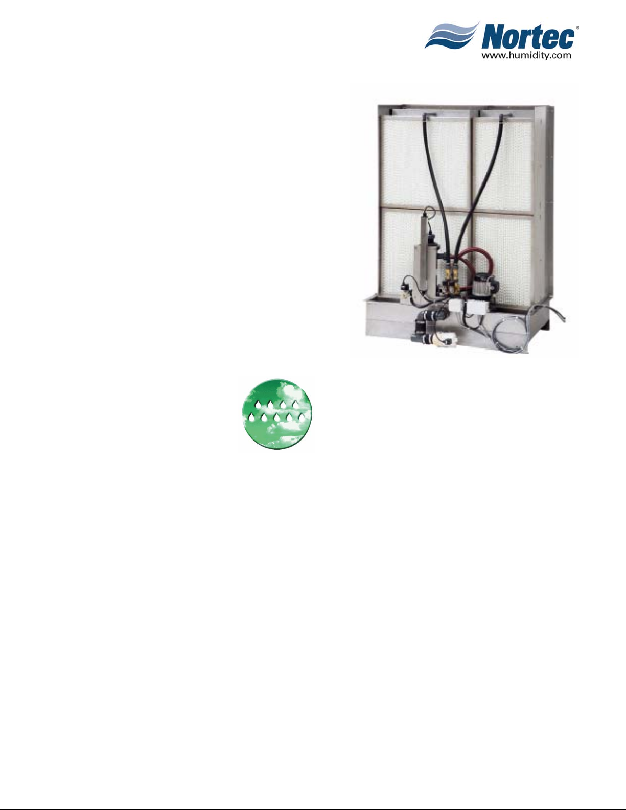
Thank you for purchasing the Nortec MH Adiabatic Air Humidifier.
The Nortec MH Adiabatic Air Humidifier incorporates the latest technical advances and
is designed to meet all recognized safety standards. Nevertheless, improper use of the
Nortec MH Adiabatic Air Humidifier may result in danger to the user or third parties
and/or damage of material assets.
To ensure safe, proper, and economical operation of the Nortec MH Adiabatic Air
Humidifier, please observe and comply with all information and safety information
contained in this installation and operating manual as well as in any separate
documentation related to the components installed in the humidification system.
If you have questions, which are not or insufficiently answered in this documentation,
please contact your Nortec representative. They will be glad to assist you.
1.2 NOTES ON THE INSTALLATION & OPERATING INSTRUCTIONS
10-00
Page 2
2008-12-03
Limitation
The product covered in this installation and operating instruction manual is solely the
Nortec MH Adiabatic Air Humidifier. The various accessories associated with the
Nortec MH Adiabatic Air Humidifier are only described in such detail that is necessary
for proper operation of the humidifier. Further information on accessories can be
obtained in the respective instructions.
These installation and operating instructions are restricted to the installation,
commissioning, operation, servicing, and troubleshooting of the Nortec MH Adiabatic
Air Humidifier and are meant for qualified personnel that are sufficiently qualified for
their respective work.
The installation and operating instructions are supplemented by various separate items
of documentation (manuals for accessories, etc.). Appropriate cross-references
are made to these publications in the installation and operating instructions.
Page 7
Symbols used in this manual
The catchword “CAUTION” designates notes in this installation
and operating instructions that, if neglected, may cause damage
and/or malfunction of the unit or other material assets.
The catchword “WARNING” used in conjunction with the general
caution symbol designates safety and danger notes in this
installation and operating instructions that, if neglected, may
cause injury to persons.
The catchword “DANGER” used in conjunction with the general
caution symbol designates safety and danger notes in this
installation and operating instructions that, if neglected, may lead
to severe injury or even death of persons.
Safekeeping
Please safeguard these installation and operating instructions in a safe place, where
they can be immediately accessed. If the equipment changes hands, the
documentation must be passed on to the new operator.
If the documentation gets misplaced, please contact your Nortec representative.
Copyright protection
The present installation and operating instructions is protected under the Copyright
Act. Passing-on and reproduction of the manual (or part thereof) as well as exploitation
and communication of the contents are prohibited without written permission by the
manufacturer. Violation of copyright terms is subject to legal prosecution and arises
liability for indemnification.
The manufacturer reserves the right to fully exploit commercial patent rights.
10-00
Page 3
2008-12-03
Page 8

2. FOR YOUR SAFETY
2.1 SAFETY OVERVIEW
General
Every person working with the Nortec MH must have read and understood the
installation and operating instructions before carrying out any work. Knowing and
understanding the contents of the installation and operating instructions is a basic
requirement for protecting all personnel against any kind of danger, to prevent faulty
operation, and to operate the unit safely and correctly.
All signs and markings applied to the unit must be observed and kept in a readable
state.
Qualification of personnel
All work (installation, operating, servicing, etc.) described in these installation and
operating instructions may only be carried out by a specialist who is well trained
and adequately qualified and is authorized by the customer.
For safety and warranty reasons any action beyond the scope of this manual must be
carried out only by qualified personnel authorized by the manufacturer.
It is assumed that all persons working with the Nortec MH are familiar and comply with
the appropriate regulations on work safety and the prevention of accidents.
Intended use
The Nortec MH Adiabatic Air Humidifier/cooler is intended exclusively for air
humidification/air cooling in air ducts or air handler within the specified operating
conditions. Any other type of application, without the written consent of your Nortec
Representative, is considered as not conforming with the intended purpose and may
lead to the Nortec MH becoming dangerous.
Operation of the equipment in the intended manner requires that all the information
in these instructions are observed (in particular the safety instructions).
10-00
Page 4
2008-12-03
Page 9
Danger that may arise from the unit
Danger: Some components of the Nortec MH are mains powered.
One may get in touch with live parts when the control unit or
the distribution boxes are open. Touching live parts may
cause severe injury or danger to life.
Prevention: Before carrying out any work set the Nortec MH out of operation
(switch off the unit, disconnect it from the mains and
stop the water supply) and secure the unit against inadvertent
power-up.
Warning: The UV lamp used in the water treatment unit (option) emits
harmful UV-C rays.
If the UV lamp is operated outside the housing, the emitted
UV-C rays may damage the eyes.
Prevention: Never operate the UV lamp outside the housing.
Warning: Badly maintained humidifiers can endanger the health.
If the unit is not properly maintained germs may grow in the
water tub which can cause illness and the humidification
boxes (and the mist eliminator) of the Nortec MH and may
affect the air passing through the humidifier.
Prevention: The Nortec MH must be cleaned in the prescribed intervals
according to the information given. The cleaning works must be
carried out correctly and the humidification boxes and the mist
eliminator boxes must be replaced after their prescribed lifetime
has elapsed.
10-00
Page 5
2008-12-03
Page 10

In case of danger
If safe operation is no longer possible, then the Nortec MH should immediately be shut
down and secured against accidental power-up.
This can be the case under the following circumstances:
• if the Nortec MH is damaged
• if the Nortec MH is no longer operating correctly
• if connections and/or piping are not sealed
• if electrical cables are defective
All persons working with the Nortec MH must report any alterations to the unit that may
affect safety to the owner without delay.
Prohibited modifications to the unit
No modifications must be undertaken on the Nortec MH without the express written
consent of the manufacturer.
For the replacement of defective components use exclusively original accessories and
spare parts available from your Nortec supplier.
3. PRODUCT OVERVIEW
3.1 MODEL OVERVIEW
The Nortec MH is available in the two base versions “flow” with direct water system
and “Reflow” with circulating water system. The following base models are available:
10-00
Page 6
2008-12-03
• Nortec MHB Flow (On/Off Control)
• Nortec MHTC Flow (Total Control Staging)
• Nortec MHB Reflow (On/Off Control)
• Nortec MHTC Reflow (Total Control Staging)
All base models can be extended in their functions by different options. In addition
there are different accessories available for all models.
Page 11
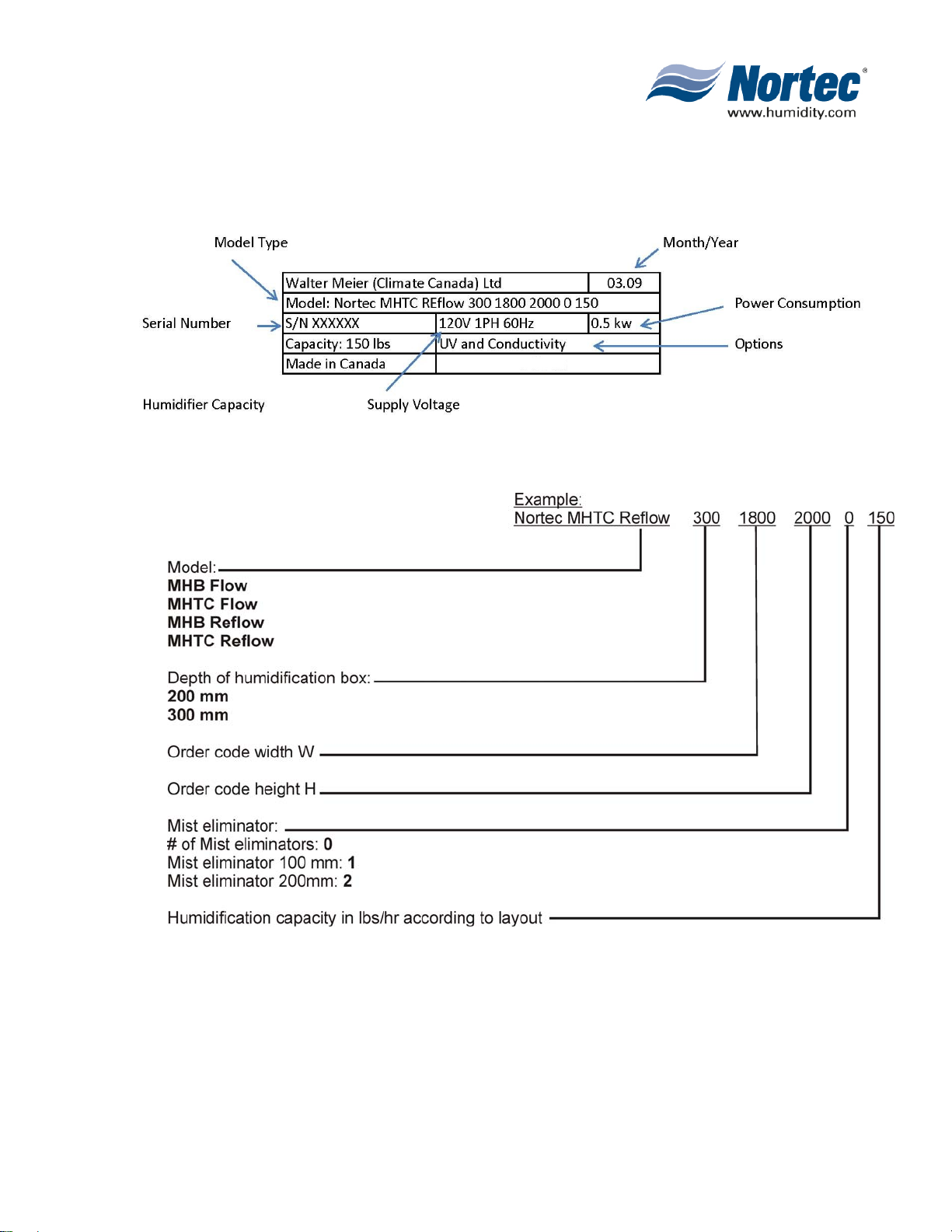
3.2 PRODUCT DESIGNATION
The product designation and the most important unit data are found on the rating plate:
3.3 TYPE KEY
10-00
Page 7
2008-12-03
Page 12
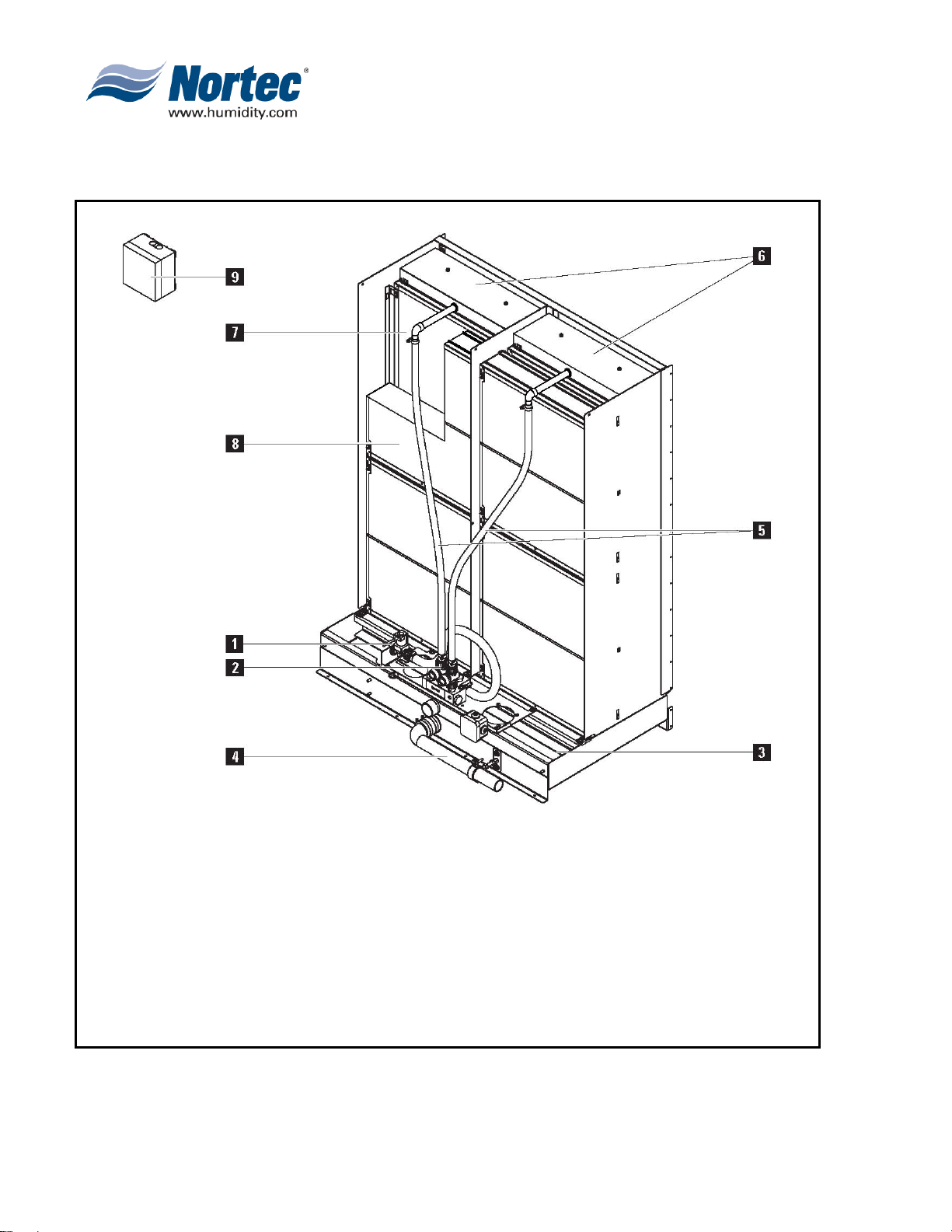
3.4 MHB Flow Model
3.4.1. MHB Flow Construction Model
10-00
Page 8
2008-12-03
Water connection on unit R 3/4 " (outside thread)
1
Volume controlling valves (adjustable manually)
2
Water tub
3
Open drain 1.5” PVC (1.66” (42 mm) OD)
4
Water hoses
5
Spray bar cap with distribution pipes
6
Humidification boxes
7
Mist eliminator (for air speed above humidification boxes >3.8 m/s) (750 fpm)
8
Control unit on/off
9
Figure 1. Construction Model – MHB Flow
Page 13
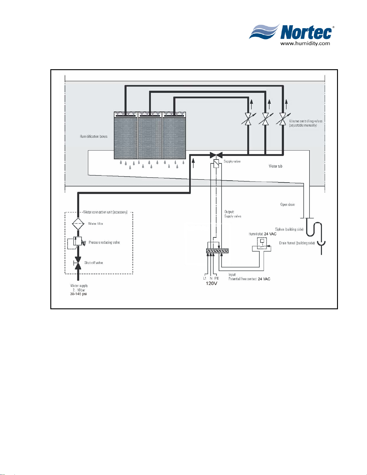
3.4.2. MHB Flow System Overview
Figure 2. System Overview – MHB Flow
Functional description
The MHB Flow model provides On/Off control by means of the MHB control unit and an
external On/Off humidistat. In case of a humidification/cooling request the supply valve
opens and the water flows via the pressure reducing valve (accessory), the water filter
(accessory) and the manually adjustable volume controlling valves to the distribution pipes
above the humidification boxes.
The distribution pipes evenly supply the water to the entire surface of the humidification
boxes where it flows down and humidifies the air flowing through the humidification boxes.
The excess water not used for humidification flows to the water tub and then directly to the
drain.
10-00
Page 9
2008-12-03
Page 14
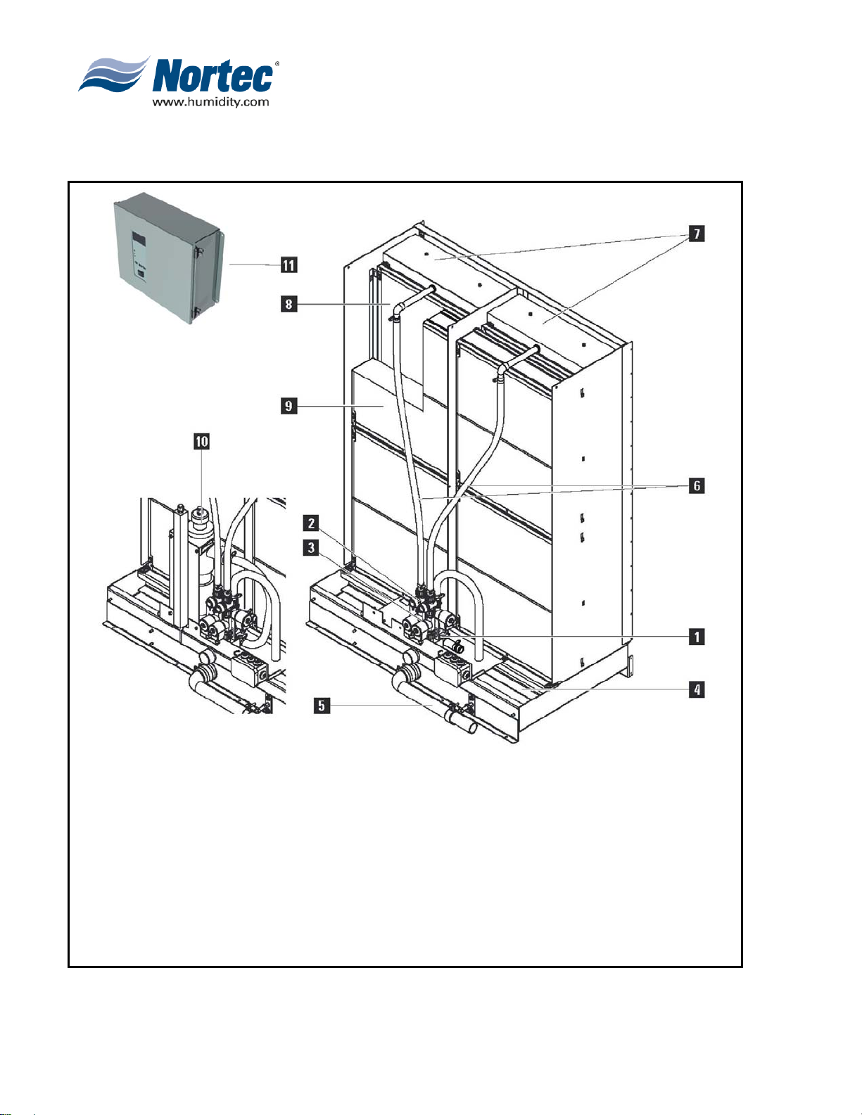
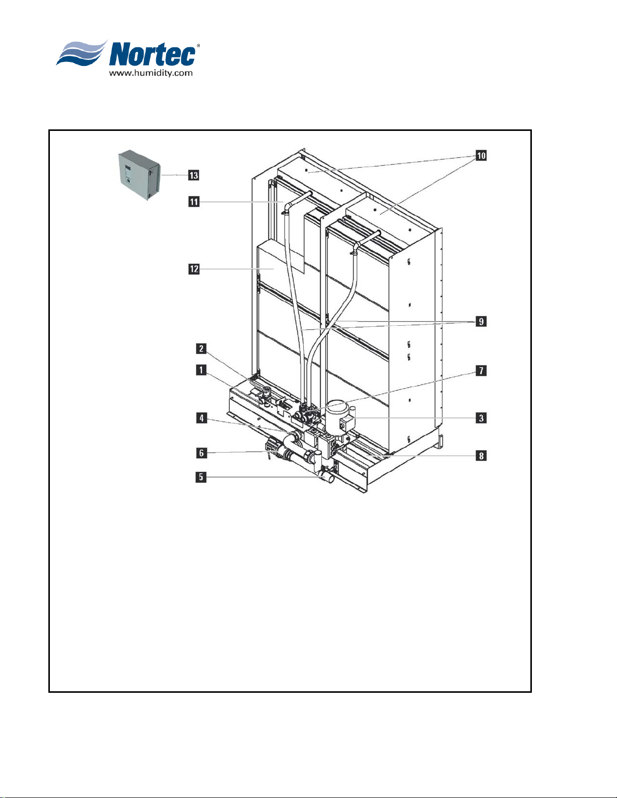
3.5 MHTC Flow Model
3.5.1. MHTC Flow Construction Model
10
11
10-00
Page 10
2008-12-03
Water connection on unit R 3/4 " (outside thread)
1
Volume controlling valves (adjustable manually)
2
Step valves (1 to 3)
3
Water tub
4
Open drain (outside diameter 1.5" PVC (1.66" (42 mm) OD)
5
Water hoses
6
Spray bar cap with distribution pipes
7
Humidification boxes
8
Mist eliminator (for air speed above humidification boxes >750 fpm) (3.8 m/s)
9
UV water treatment (option)
MHTC Total Control Unit
Figure 3. Construction Model – MHTC Flow
Page 15
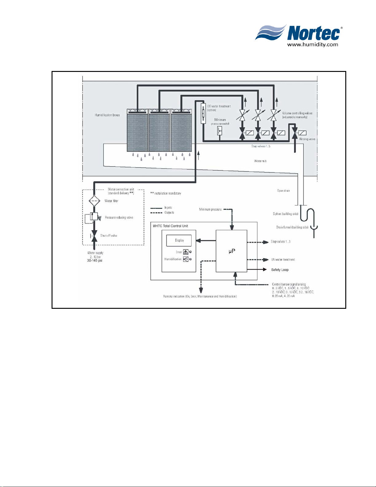
3.5.2. MHTC Flow System Overview
Figure 4. System Overview – MHTC Flow
Functional description
The MHTC Flow model provides multistep control by means of the MHTC Total Control unit and the
step valves (1, 2 or 3 step valves depending on the humidifier capacity). The MHTC Total Control unit
(for wall mounting) processes analog sensor/control signals and uses them to control the step valves.
This allows multistep control (1 to 3 steps depending on the humidifier capacity) which improv es
control accuracy compared to the MHB Flow model.
In case of a humidification/cooling request one, two or all three step valves open (depending on the
request). The water flows via the manually adjustable volume controlling valves to the distribution
pipes above the humidification boxes.
The distribution pipes evenly supply the water to the entire surface of the humidification boxes where
it flows down and humidifies the air flowing through the humidification boxes. The excess water not
used for humidification flows to the water tub and then directly to the drain. If the MHTC Flow model
is equipped with the optional UV water treatment (installed in the water supply) the water is
continuously sterilized during the humidification process.
2008-12-03
10-00
Page 11
Page 16
3.6 MHB Reflow Model
3.6.1. MHB Reflow Construction Model
10
11
12
13
10-00
Page 12
2008-12-03
Water connection on unit R 3/4 " (outside thread)
1
Level-controlled supply valve
2
Circulation pump
3
Overflow
4
Drain
5
Drain valve
6
Volume controlling valves (adjustable manually)
7
Water tub
8
Water hoses
9
Spray bar caps with distribution pipes
Humidification boxes
Mist eliminator (for air speed above humidification boxes >750 fpm) (3.8 m/s)
MHB Control Unit
Figure 5. Construction Model – MHB Reflow
Page 17
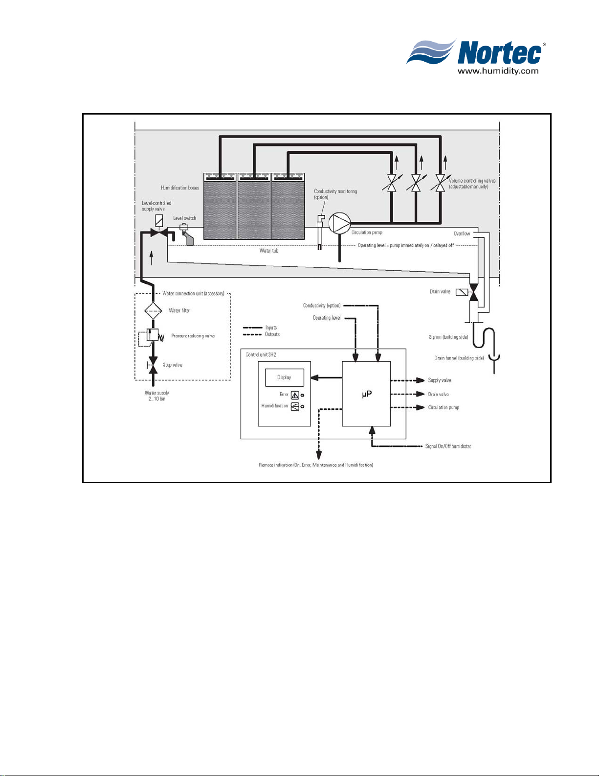
3.6.2. MHB Reflow System Overview
Figure 6. System Overview – MHB Reflow
Functional description
The water tub is filled up to a preset upper level via the level-controlled supply valve. When the water
level in the tub drops below a certain limit, the level-controlled supply valve opens until the upper limit
is reached again. The pump is activated whenever the float is high and continues to operate for a
preset time after the float level drops.
The MHB Reflow model provides On/Off control by means of the MHB control unit and an external
On/Off humidistat. In case of a humidification/cooling request the pump is activated. The water flows
via the manually adjustable volume controlling valves to the distribution pipes above the
humidification boxes.
The distribution pipes evenly supply the water to the entire surface of the humidification boxes where
it flows down and humidifies the air flowing through the humidification boxes. The excess water not
used for humidification flows to the water tub. To prevent accumulation of mineral residues and the
formation of germs in the water tub, the tub is completely drained periodically (interval or time
controlled).
2008-12-03
10-00
Page 13
Page 18
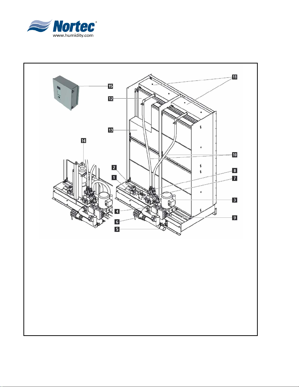
3.7 MHTC Reflow Model
3.7.1. MHTC Reflow Construction Model
10
11
12
13
14
15
10-00
Page 14
2008-12-03
Water connection on unit R 3/4 " (outside thread)
1
Level-controlled supply valve
2
Circulation pump
3
Overflow
4
Drain
5
Drain valve
6
Step valves (1 to 3)
7
Volume controlling valves (adjustable manually)
8
Water tub
9
Water hoses
Spray bar cap with distribution pipes
Humidification boxes
Mist eliminator (for air speed above humidification boxes >750 fpm) (3.8 m/s)
UV water treatment (option)
MHTC Total Control Unit
Figure 7. Construction Model – MHTC Reflow
Page 19

3.7.2. MHTC Reflow System Overview
Figure 8. System Overview – MHTC Reflow
Functional description
The water tub is filled up to a preset upper level via the level-controlled supply valve. When
the water level in the tub drops below a certain limit, the level-controlled supply valve opens
until the upper limit is reached again.
The MHTC Reflow model provides multistep control by means of the MHTC Total Control
unit and the step valves (1, 2 or 3 step valves depending on the humidifier capacity). The
MHTC Total Control unit (for wall mounting) processes analog sensor/control signals and
uses them to control the step valves. This allows multistep control (1 to 3 steps depending
on the humidifier capacity) which improves control accuracy compared to the MHB Reflow
model.
2008-12-03
10-00
Page 15
Page 20

In case of a humidification/cooling request, the circulation pump starts and one, two, or all
three step valves open (depending on the request). The water flows via the manually
adjustable volume controlling valves to the distribution pipes above the humidification boxes.
The distribution pipes evenly supply the water to the entire surface of the humidification
boxes where it flows down and humidifies the air flowing through the humidification boxes.
The excess water not used for humidification flows to the water tub.
To prevent accumulation of mineral residues and the formation of germs in the water tub,
the tub is completely drained periodically (Interval or time controlled). Additionally further
hygiene functions can be activated: Operation-dependent draining of the water tub
(conductivity or fill cycle controlled) as well as cleaning and drying of the humidification
boxes.
If the MHTC Reflow model is equipped with the optional UV water treatment, a particular
amount of water is led to the UV water treatment unit where it is sterilized.
.
3.8 STANDARD DELIVERY
Standard delivery includes:
• Nortec MH Adiabatic Air Humidifier according to type designation (disassembled)
equipped with options according to packing list.
• Ordered accessories with operating instructions, packed separately.
• Installation and operating instructions (this document).
• Operating instructions control unit MHTC (models with control unit MHTC only)
• Spare parts list.
3.9 STORING / TRANSPORT / PACKAGING
Storing
Store the unit and unit components in a protected area meeting the following
requirements:
• room temperature: 1 ... 40°C (34-104ºF)
• room humidity: 10 ... 75 %rh
Transport
For optimum protection always transport the unit and the unit components in the
original packaging.
The weight of the unit components depends on the unit model. To move larger unit
components always ask a second person for assistance.
Packaging
Keep the original packaging of the Nortec MH for later use. In case you wish to
dispose of the packaging, observe the local regulations on waste disposal. Never
dispose of the packaging to the environment.
10-00
Page 16
2008-12-03
Page 21

10-10
INSTALLATION
10-10
Page 17
2008-12-03
Page 22

1. INSTALLATION
1.1 IMPORTANT NOTES ON THE MOUNTING AND INSTALLATION WORK
Qualification of personnel
All mounting and installation work must be carried out only by well qualified personnel
authorized by the owner. It is the owner’s responsibility to verify proper qualification of
the personnel.
General note
Strictly observe and comply with all information given in the present installation and
operating instructions regarding the mounting of the unit and the installation of water
and electricity.
Observe and comply with all local regulations dealing with water and electrical
installations.
Safety
The electrical installation for the unit models MHB Flow, MHTC Flow, MHB Reflow,
MHTC Reflow requires the removal of the control unit cover. Please note the following:
Danger of electrical shock! You may get in touch with live parts
when the control unit is open. The control unit must be connected
to the mains only after all mounting and installation work has been
completed and the control unit cover has been relocated properly.
The electronic components inside the control unit are very
sensitive to electrostatic discharge. When the unit is open for
installation work, appropriate measures must be taken to protect
these components against damage caused by electrostatic
discharge (ESD protection).
10-10
Page 18
2008-12-03
Page 23

1.2 UNIT MOUNTING
1.2.1. Note on the locating the unit
Usually, the design and dimensioning of the ventilation duct/air handler as well as the location
of the Nortec MH inside the duct are determined, recorded and specified when planning the
entire system. Prior to installation, however, make sure the following criteria have been taken
into consideration:
• For operation with fully demineralised water: Fully demineralised water is aggressive! For
this reason, all components located close to the humidification unit (duct/ air handler,
fastening material, drain pipe, etc.) must be made of corrosion-proof steel or plastic.
• For installation and maintenance of the humidification unit a viewing window and a
sufficiently large maintenance door must be available in the duct/ air handler.
• In the area of the humidification unit the ventilation duct/ air handler must be waterproof.
• Important! An air filter must be installed at the air inlet of the humidification unit. The filter
must meet the quality standards (MERV 11 (Note WMCI specifies EU7 (f7) which is
equivalent to MERV 11) ASHRAE 52.2 or better.
• In case of low ambient temperature the duct must be insulated to prevent the moist air from
condensing inside the duct.
• If the system is equipped with a heater, make sure it is at least 20” (0.5 m) away from the
humidification unit.
• If silencers are mounted in the air conditioning units make sure to locate the humidification
unit at a minimum distance of 10’ (3 m) before or after the silencers.
• In order to avoid drops seeping over the humidification boxes, an even air flow over the full
cross section of the humidification unit must be guaranteed. If necessary, rectifiers or
perforated plates must be installed on the building side before the humidifier. If the air
velocity through the humidification boxes exceeds 750 fpm (3.8 m/s), mist eliminator must
be installed.
• The effective height of the siphon in the drain line depends on the duct pressure. Correct
dimensioning of the siphon is the customer’s responsibility.
10-10
Page 19
2008-12-03
Page 24

1.2.2. Mounting Process
Figure 1. Mounting Process – Step 1
Align the water tub to the centre of the duct, then use a level check water tub to the duct
lengthwise and crosswise. Shim the tank as required until it is level.
Note: Install four self-tapping screws 1/4 UNC x 3/4" on each side of the tub to secure it in
place.
10-10
Page 20
2008-12-03
Page 25

Figure 2. Mounting Process – Step 2
Fix the cross beam “B” to the water tub using four hexagon socket screws 1/4 UNC x 1/2" and
washers.
10-10
Page 21
2008-12-03
Page 26

Figure 3. Mounting Process – Step 3
Hint: With close space conditions we recommend to install the EPDM sealing profile to the vertical
supports before installing the supports. Please refer to step 7 for more information.
Carefully mount the left “D” and the right vertical support “E” onto the threaded bolts of the
water tank, then fix each support with four 1/4 UNC nuts and washers (do not overtighten the nuts).
Important! Before tightening the nuts make sure the holes of the vertical supports seat solidly
on the sheet metal of the water tub and do not stuck on the collar of the threaded bolt!
10-10
Page 22
2008-12-03
Page 27

Figure 4. Mounting Process – Step 4
Carefully mount the vertical intermediate support(s) “F” (number depending on t he unit size)
onto the threaded bolts of the water tub, then fix each support with two 1/4 UNC nuts and washers
to the water tub (do not overtighten the nuts) and with a hexagon socket screw 1/4 UNC x 1/2" and a
washer to the cross beam.
Important! Before tightening the nuts make sure the holes of the intermediate support seat solidly on the
sheet metal of the water tub and do not stick on the collar of the threaded bolt!
10-10
Page 23
2008-12-03
Page 28

Figure 5. Mounting Process – Step 5
Fix the front bracket “G” to each vertical support using two hexagon socket screws 1/4 UNC x 1/2" and
washers.
Important! Before tightening the screws make sure all supports are vertically exactly aligned!
10-10
Page 24
2008-12-03
Page 29

Fix one mounting bracket “H” to each vertical support and intermediate support using a hexagon
socket screw 1/4 UNC x 1/2", a 1/4 UNC nut and a washer (see figure above). Important: With multiple
intermediate supports all mounting brackets must be mounted to the supports on the same side. The
mounting brackets fixed to the outermost supports must be mounted always outside (between
duct wall and support) and point inward.
Finally align the supports, then fix the mounting brackets to the duct ceiling using two self-tapping
screws 1/4 UNC x 3/4" each.
Figure 6. Mounting Process – Step 6
10-10
Page 25
2008-12-03
Page 30

Figure 7. Mounting Process – Step 7
The air gap between the outermost vertical supports and the duct walls as well as between the
front bracket and the duct ceiling must be sealed using EPDM sealing profile (accessory). Cut the EPDM
sealing profiles to the desired length (channel height and channel width plus cm allowance). Fix the
EPDM sealing profiles to the outermost vertical supports and to the front bracket using the clamping
brackets and self-tapping screws #10 x 3/4" supplied. Tailor the EPDM sealing profiles to the duct height
and the duct width, then fix them to the duct walls and the duct ceiling using the clamping brackets and
self-tapping screws #10 x 3/4" supplied (number of self-tapping screws to be used as required).
Note: In place of the EPDM sealing profiles also sheet metal angles of stainless steel (not included
in the delivery) may be used for the sealing.
10-10
Page 26
2008-12-03
Page 31

Figure 8. Mounting Process – Step 8
Fix hydraulic unit to the water tub and the cross beam using four hexagon socket screws 1/4 UNC x 1/2"
and washers.
Important: Remove the closing plug “H” from the circulation pump inlet before mounting
the hydraulic units MHB Reflow or MHTC Reflow.
10-10
Page 27
2008-12-03
Page 32

Figure 9. Mounting Process – Step 9
Assemble the drains according to the corresponding figure above (the drai ns can be assembled
for draining to the right or to the left) and fix it to the water tank using the mounting bracket provided.
10-10
Page 28
2008-12-03
Page 33

Figure 10. Mounting Process – Step 10
Starting from the bottom, install the humidification boxes in each row: Hook the mounting clips
of the boxes into the corresponding openings of the supports, then push the humidification box
downwards until it comes to a stop (arrangement of the humidification boxes according to the
installation drawing included in the delivery).
NOTE: In systems with an air speed >925 fpm (4.7 m/s) through the boxes the cover sheet “K” must be
mounted to all topmost humidification boxes before installing them.
10-10
Page 29
2008-12-03
Page 34

Figure 11. Mounting Process – Step 11
Only for units with mist eliminator: Hook the mounting brackets into corresponding openings
of the vertical supports, then push the brackets downwards until it comes to a stop (if necessary
use a rubber mallet).
Note: arrangement of the mounting brackets according to the detail figures above and the installation
drawing included in the delivery.
10-10
Page 30
2008-12-03
Page 35

Figure 12. Mounting Process – Step 12
Only for units with mist eliminator: Starting from the bottom, install the mist eliminator in
each row: Hook the mounting clips of the mist eliminator into the corresponding openings of the
mounting brackets, then push the mist eliminator downwards until it comes to a stop.
Note: arrangement of the mist eliminator according to the installation drawing included in the
delivery.
10-10
Page 31
2008-12-03
Page 36

Figure 13. Mounting Process – Step 13
Mounting the spray cap bars: Push the two tongues on the back side of the trickling hood underneath
the frame sheet of the humidification box (see detail above), then pivot the spray cap bars
downwards. The two brackets on the front side of the spray cap bar must engage in the frame
(see detail above) of the humidification box.
Note: arrangement of the spray cap bars according to the installation drawing included in the
delivery.
10-10
Page 32
2008-12-03
Page 37

10-20
PLUMBING &
ELECTRICAL
INSTALLATION
10-20
Page 33
2008-12-03
Page 38

1.0 WATER INSTALLATION
1.1 OVERVIEW WATER INSTALLATION
Figure 1. MHB Flow – Water Installation
10-20
Page 34
2008-12-03
Figure 2. MHTC Flow – Water Installation
Page 39

Figure 3. MHB & MHTC Reflow – Water Installation
1.2 NOTES ON WATER INSTALLATION
Water supply
The water supply is to be carried out according to the figure found in this chapter and
the applicable local regulations for water installations. The indicated connection
specifications must be observed.
• The installation of the shut-off valve, pressure reducing valve and a water filter
should be made as close as possible to the unit.
Notes on water quality:
• For the water supply of the Nortec MH, use exclusively untreated drinking water,
Reverse Osmosis Water, fully demineralised water or partly softened water.
• The use of additives such as corrosion inhibitors, disinfectants, etc., is not allowed,
since these additives may endanger health and affect proper operation.
• If the Nortec MH shall be operated with softened water, please contact your
Nortec supplier.
• The connection material must be pressure-proof and certified for use in drinking
water supply systems.
• Important: Before connecting the water line to the unit, the line must be flushed
thoroughly.
The thread at the humidifier connection is made of plastic. To
avoid overtightening, the union nut of the water pipe must be
tightened by hand only.
10-20
Page 35
2008-12-03
Page 40

Water drain
The water drain is to be carried out according to the figure found in this chapter and
the applicable local regulations for water installations. The indicated connection
specifications must be observed.
• Make sure the drain line is installed with a constant down-slope to the siphon of the
building.
• Make sure the drain pipe is correctly fixed and easily accessible for inspections
and cleaning purposes.
• The minimum inside diameter of the drain pipe of 1.5" (38.1 mm) must be
maintained throughout the entire length!
When operating the Nortec MH with fully demineralised water fully demineralised
water is aggressive! For this reason, use exclusively plastic or stainless steel
installation materials.
1.3 ELECTRICAL INSTALLATION
1.3.1 Leading the electrical cables out of the duct
Note: The electric installation of the unit models for the Nortec MH “Flow” and “Reflow” is the
clients responsibility.
Figure 4. Leading the electrical cables out of the duct
• Lead the low voltage multi conductor control cable via liquid tight conduit fittings, “A” out of
the duct.
• MH Reflow models – Install a power cable rated for plenum use and meeting all local
electrical codes (not provided) to the wires in the pump motor’s junction box “B”. Route
the power cable out of the duct via liquid tight conduit fitting.
10-20
Page 36
2008-12-03
Page 41

1.3.2 Mounting the MH Control Unit
Figure 5. Mounting the MH Control Unit
1. Fix the control panel to the wall using 4 x ¼” screws (not provided).
2. Connect the multi conductor control cables from the hydraulic unit to the corresponding
terminals in the control unit according the appropriate wiring diagram.
Important: all cables must be lead into the control unit via strain reliefs installed into the
openings in the bottom of the control panel housing.
3. MH Reflow models – Connect the power cable from the pump motor to the
corresponding terminals according to the appropriate wiring diagram.
10-20
Page 37
2008-12-03
Page 42

1.3.3 Wiring Diagram Nortec MH Flow
10-20
Page 38
2008-12-03
Figure 7. Wiring Diagram MH Flow
Page 43

1.3.4 Wiring Diagram Nortec MH Reflow
Figure 8. Wiring Diagram MH Reflow
10-20
Page 39
2008-12-03
Page 44

THIS PAGE INTENTIONALLY LEFT BLANK
10-20
Page 40
2008-12-03
Page 45

10-30
OPERATION
10-30
Page 41
2008-12-03
Page 46

1.0 OPERATION
1.1 PUTTING INTO OPERATION
Proceed as follows when putting the Nortec MH into operation:
• Examine the Nortec MH and installation for possible damage.
Damaged devices or devices with damaged installation may present
danger to human life or cause severe damage to material assets.
Damaged units and/or units with damaged or faulty installation must not
be operated.
• Models MHB Flow, MHTC Flow, MHB Reflow, MHTC Reflow: Make sure the connecting
box(es) and the control unit are closed and that all cables are lead through cable glands.
• Open the shut-off valve in the water supply line.
• Switch on the service switch in the mains supply.
• Models MHTC Flow, MHB Reflow, MHTC Reflow: switch on the MH control unit (the unit
switch lights up).
• Note: regarding the operation of the MH control unit please observe the information given
in the separate operating instructions to the MH control unit.
• Check the settings of the humidistat/thermostat or the humidity controller, respectively. If
necessary, adjust settings.
1.2 ADJUST THE VOLUME CONTROLLING VALVES
Figure 1. Adjusting the Volume Control Valves
After first time commissioning of the Nortec MH, the volume controlling valves must be
adjusted to the local operating conditions according to the separate instructions.
10-30
Page 42
2008-12-03
Page 47

1.3 NOTES ON OPERATION
During operation of the Nortec MH the humidification system has to be inspected weekly. On
this occasion check the following:
• the water for any leakage.
• the humidifier and the other system components for correct fixing and any damage.
• the electric installation for any damage.
• unit models with MH control unit: Check operating information in display level and whether
or not a warning or error message is present.
If the inspection reveals any irregularities (e.g. leakage, error indication) or any damaged
components take the Nortec MH out of operation as described in chapter. Then, have the
malfunction be eliminated or the damaged component be replaced by a well trained specialist
or a service technician from your Nortec supplier.
1.4 TAKING OUT OF OPERATION
In order to take the Nortec MH out of operation (e.g. to perform maintenance works, to
eliminate a malfunction, etc.) perform the following steps:
Close the shut-off valve in the water supply line.
Models MHB Reflow and MHTC Reflow: empty the water tub.
Models MHB Reflow and MHTC Reflow: Start manual draining (see operating instructions of
the MH control unit) and wait until the water tub is empty.
Models MHTC Flow, MHB Reflow, and MHTC Reflow: switch off control unit.Important: If the
unit has to be switched off because of a malfunction, please note the code of the actual error
message.
Isolate all components of the Nortec MH from the mains and secure system against
accidentally being reconnected to the mains.
If work has to be carried out on the Nortec MH, switch off the ventilation system and secure
the system against accidentally being switched on.
Note: if the Nortec MH is not be used for a longer period of time the MHB Flow model should
be taken out of operation as described above. However, the MHTC Flow, MHB Reflow, and
MHTC Reflow should stay operable to keep the hygiene functions active.
10-30
Page 43
2008-12-03
Page 48

THIS PAGE INTENTIONALLY LEFT BLANK
10-30
Page 44
2008-12-03
Page 49

10-40
MAINTENANCE &
TROUBLESHOOTING
10-40
Page 45
2008-12-03
Page 50

1.0 MAINTENANCE
1.1 IMPORTANT NOTES ON MAINTENANCE
Qualification of personnel
All maintenance work must be carried out only by well qualified and trained
personnel authorized by the owner. It is the owner’s responsibility to verify proper
qualification of the personnel.
General note
The instructions and details for maintenance work must be followed and upheld.
Only the maintenance work described in this documentation may be carried out.
Only use original Nortec spare parts to replace faulty parts.
Safety
Before carrying out any maintenance work take the Nortec MH out of operation as
described in this manual and secure the unit against inadvertent power-up. In
addition, take the ventilation system out of operation as described in the operation
instructions of the ventilation system and secure the ventilation system against
inadvertent power-up.
The Nortec MH must be maintained in the prescribed intervals, the cleaning work
must be carried out correctly and the humidification boxes and the mist eliminator
boxes must be replaced after their prescribed lifetime has elapsed.
WARNING! If the unit is insufficiently maintained germs which
can cause illness, may grow in the water tub and the
humidification boxes (and the mist eliminator) of the Nortec MH
and may affect the air passing through the humidifier.
1.2 MAINTENANCE INTERVALS
In order to maintain operational safety the Nortec MH must be maintained in regular
intervals. The time interval for the maintenance is to be adapted to the operating
conditions. The hygiene status depends mainly on the quality of the humidifier water
but also on the adherence to the exchange intervals of the upstream air filter, the air
velocity and the micro-biological and chemical composition of the supply air.
Therefore the maintenance intervals must be determined for each system separately.
The first maintenance must be carried out after 800 operating hours. Depending on
the encountered hygiene status during the first maintenance the interval time must
be decreased or increased.
10-40
Page 46
2008-12-03
Page 51

In any case the Nortec MH is to be maintained at least twice annually.
On units equipped with a MH control unit (MHTC Flow, and MHTC Reflow) the
maintenance interval can be programmed. As soon as the maintenance time has
elapsed, a maintenance message is displayed to draw your attention to the pending
maintenance. To determine the maintenance interval time, the above described
procedure can be used.
1.3 MAINTENANCE WORK
Component Work to be carried out
Humidification boxes
and mist eliminator
boxes.
Water tank
Frame structure
Duct section
downstream of the
humidifier
Hydraulic unit
Dismantle and check the humidification boxes (and
mist eliminator boxes). Clean the frame of the boxes
with a combined detergent and disinfectant. If the
humidifier fleece is heavily soiled, the humidification
boxes have to be replaced.
Note: If the humidification boxes indicate strong dust
deposit, the air filter of the ventilation system is to be
controlled (filter quality at least MERV 11 according to
ASHRAE 52.2 Standard).
Check water tank for soiling (dust, slime, mineral
deposit, etc.) and clean with a combined detergent and
disinfectant.
Note: The actual hygiene status indicates, whether the
maintenance interval time must be decreased or
increased.
Check screw connections of the frame structure, tight
loose screw connections. Clean frame structure with a
combined detergent and disinfectant.
Check the duct section behind the humidifier
(downstream) for collection of residual water. If
residual water is present: Check air velocity above the
humidification boxes (without mist eliminator max. 690
Fpm (3.5 m/s), with mist eliminator max. 885 Fpm (4.5
m/s), respectively). Mount mist eliminator if necessary.
Clean duct with a combined detergent and disinfectant.
Check connections and components for sealing and
correct fastening. Seal/replace leaky components,
replace defective components, and fasten loose
components. Carefully clean the components of the
hydraulic unit with a combined detergent and
10-40
Page 47
2008-12-03
Page 52

disinfectant.
Water installation
Spray Bar Cap
Drain line with Siphon
UV water treatment
(Option)
Electric installation
Check water the water hoses of the humidifier for
cracks and correct fastening, replace defective hoses.
Carefully clean the hoses with a combined detergent
and disinfectant.
Check water supply line for sealing and seal if
necessary. Dismantle water filter (if present) and clean
it.
Dismantle the spray bar cap and check the holes in the
water distribution pipes for mineral deposit. If
necessary, dismantle the water distribution pipes and
remove the mineral deposit. Clean spray bar cap and
water distribution pipes with a combined detergent and
disinfectant.
Check and clean with a combined detergent and
disinfectant, if necessary.
Dismantle the UV lamp. Carefully clean glass tube and
UV lamp. After max. of 8000 operating hours the UV
lamp must be replaced.
Check all cables and components for correct fastening,
correct function and defects. Have defective
components replaced or loose components fastened
by a qualified specialist.
10-40
Page 48
2008-12-03
Page 53

1.4 DISMANTLING AND INSTALLATION WORKS
1.4.1 Dismantle and install the mist eliminator and humidification boxes.
1. Undo the hose clamps, then pull off the
hoses from the connections on the spray
bar caps.
2. Lift the spray bar caps on the water
connection side and remove them to the
front.
3. Starting from the top remove the mist
eliminator boxes (push box upwards and
remove it to the front).
4. Release the fixing clip in the middle of
the mounting bracket by pressing slightly
on the vertical support, then carefully
push the mounting bracket upwards and
remove it. Repeat this step for all
mounting brackets.
5. Starting from the top remove the
humidification boxes (push box upwards
and remove it to the front).
The installation of the cleaned or the new humidification boxes/mist eliminator boxes
follows the reverse dismantling order.
10-40
Page 49
2008-12-03
Page 54

1.4.2 Dismantle and install the UV lamp (option)
The installation of the UV lamp follows the reverse dismantling order.
CAUTION! When installing the UV lamp, make sure to hold the lamp
until it is completely inserted. Under no circumstances let the lamp fall
inside the holder, since this could damage the lamp.
1. Pull the retaining clip out to release the
UV light plug.
2. Carefully lift the plug and pull the UV
lamp out of the housing.
3. Remove glass tube to the top.
4. Clean glass tube outside and inside
with a lint-free and soft cloth.
10-40
Page 50
2008-12-03
Page 55

1.5 RESETTING THE MAINTENANCE INDICATION
When maintenance work has been completed the maintenance indication must be reset
on the unit models flow MHTC Flow, and MHTC Reflow (yellow LED lights). For that
purpose, please observe the information given in the separate operating instructions for the
MH control unit.
2.0 TROUBLESHOOTING
Important! Most operational malfunctions are not caused by faulty equipment but rather by
improper installation or disregarding of planning guidelines. Therefore, a complete fault
diagnosis always involves a thorough examination of the entire system.
2.1 TROUBLESHOOTING LIST
PROBLEM CAUSE SOLUTION
Residual water in the
section of the duct behind
(downstream) the Nortec
MH
Humidity/Cooling
demand present however
the Nortec MH does not
humidify.
Maximum
humidification/cooling
capacity is not reached.
Air velocity above the
humidification boxes is too
high. Units without mist
eliminator max. (750 Fpm)
3.8 m/s, Units with a 4”
(100 mm) mist eliminator
max. 885 fpm (4 .5 m/s),
with a 7.87” (200 mm) mist
eliminator max. 1082 fpm
(5.5 m/s).
Water drain is leaking.
Shut-off valve in the water
supply line closed.
Reflow Models: Circulation
pump defective.
System incorrectly
dimensioned (insufficient
capacity).
Insufficient water supply
capacity
Models with MH control
unit: Output limitation
active.
Install mist eliminator or
reduce air velocity in the
duct.
Check/seal water drain.
Open shut-off valve.
Replace circulation pump.
Contact your Nortec
supplier.
Check water supply,
increase water pressure.
Deactivate output
limitation (see separate
operating instructions for
MH control unit).
10-40
Page 51
2008-12-03
Page 56

Note: On units equipped with a MH control unit (MHTC Flow, MHB Reflow, and MHTC
Reflow) malfunctions during operation are indicated by a corresponding event message in
the display. For that purpose, please observe the information given in the separate
operating instructions for the MH control unit.
2.2 NOTES ON FAULT ELIMINATION
In order to eliminate faults, the Nortec MH must be set out of operation
as described in this manual. Disconnect the unit from the mains and
secure the unit against in advertent power-up.
Only allow trained and qualified personnel to repair faults. Faults relating to electrical
installation must only be carried out by authorized personnel or your Nortec representative’s
service technician.
Repair work and replacement of faulty components must only be carried out by your Nortec
representative’s service technician!
3.0 TAKING OUT OF SERVICE / DISPOSAL
3.1 TAKING OUT OF SERVICE
If the Nortec MH must be replaced or if the humidification system is not needed any more,
proceed as follows:
1. Take the unit out of operation as described in this manual.
2. Have the unit (and all other system components, if necessary) un-mounted by a qualified
service technician.
3.2 DISPOSAL / RECYCLING
Dismantled components must be disposed of and/or recycled according to the local
regulations. In case of doubt please contact your Nortec supplier.
10-40
Page 52
2008-12-03
Page 57

4.0 PRODUCT SPECIFICATIONS
4.1 TECHNICAL DATA
Control
Control supply charge 120 VAC /
Circulation pump supply voltage --- --- 120 VAC/60 Hz
Control signals Potential
Control characteristics On/Off Control Step On/Off Control Step
Control accuracy Control accuracy depends on air conditions, control distance,
Max. admissible air speed above
humidification boxes
Water supply R ¾” outside thread
Water drain
Admissible water supply pressure
Admissible water temperature 41-113ºF (5-45ºC)
Water quality
Pressure drop Typically 0.44 IWC @ 500 fpm, 90% rh
Admissible ambient temperature (Control
unit)
Admissible ambient humidity (Control unit) Max. 75% rh Max. 75% rh Max. 75% rh Max. 75% rh
Degree of protection of Control unit
Degree of protection of pump, valves, etc.
Fire classification of humidification medium UL 900 Class 1
Accessories
Supply valve connection (24V)
Drain water connection (24 V)
Duct humidistat
Room humidistat
Duct humidity sensor
Room humidity sensor
Remote indication PCB
On/Error/Maintenance/Humidification
Options
UV water treatment
Drain valve (24VAC)
Conductivity monitoring
Nortec Links BMS Interface
Nortec OnLine Web Control
S = Standard Equipment
y = Option
MHB FLOW MHT C FLOW MHB
REFLOW
Humidistat Total Controller
120 VAC /
60 Hz
free contact
of an
external
humidistat /
thermostat
water quality and probably on the number of On/Off cycles.
3.8 m/s / 750 fpm (4.5 m/s / 885 fpm with 4” (100 mm) mist
1.5" PVC (1.66" (42 mm) OD) outside diameter of tube
Tap water, Reverse Osmosis, softened or fully demineralized water.
34…104ºF
(1…40ºC)
S S S S
y y y y
y y y y
y y y y
60 Hz
0…5 VDC
1…5 VDC
0…10 VDC
2…10 VDC
0…16 VDC
3.2…16 VDC
0..20 mA
4..20 mA
eliminator, 5.5 m/s
34…104ºF
1…40ºC
y
y
S S S
y
y
Control MHB
120 VAC /
60 Hz
Potential
free contact
of an
external
humidistat /
thermostat
34…104ºF
1…40ºC
S S
S S
y y
MHTC
REFLOW
Total Controller
120 VAC /
60 Hz
0…5 VDC
1…5 VDC
0…10 VDC
2…10 VDC
0…16 VDC
3.2…16 VDC
0..20 mA
4..20 mA
34…104ºF
1…40ºC
y
y
y
y
10-40
Page 53
2008-12-03
Page 58

4.2 UNIT DIMENSIONS
UH: 25.4…120.0 (645…3045) (Increments of 2.95”)
UW: 23.8…118.3 (604…3004) (Increments of 3.94”)
UD:
Max. humidification
efficiency
85% 8” (200 mm) ---- 22.5” (573 mm)
85% 8” (200 mm) 4” (100 mm) 22.5” (573 mm)
85% 8” (200 mm) 26.5 (673 mm)
95% 12” (300 mm) ---- 26.5 (673 mm)
95% 12” (300 mm) 4” (100 mm) 26.5 (673 mm)
95% 12” (300 mm) 30.4” (773 mm)
Depth Humidification
box
UA: MHB / MHTC Flow 3.8” (97 mm)
MHB / MHTC Reflow 5.9” (131 mm)
Depth Mist
eliminator
Depth UD
10-40
Page 54
2008-12-03
Page 59

WARRANTY
(1) WALTER MEIER INC. and/or WALTER MEIER LTD. (hereinafter collectively referred
to as THE COMPANY), warrant for a period of two years after installation or 30 months
from manufacturer’s ship date, whichever date is earlier, that THE COMPANY’s
manufactured and assembled products, not otherwise expressly warranted (with the
exception of the cylinder), are free from defects in material and workmanship. No
warranty is made against corrosion, deterioration, or suitability of substituted materials
used as a result of compliance with government regulations.
(2) THE COMPANY’s obligations and liabilities under this warranty are limited to furnishing
replacement parts to the customer, F.O.B. THE COMPANY’s factory, providing the
defective part(s) is returned freight prepaid by the customer. Parts used for repairs are
warranted for the balance of the term of the warranty on the original humidifier or
90 days, whichever is longer.
(3) The warranties set forth herein are in lieu of all other warranties expressed or implied
by law. No liability whatsoever shall be attached to THE COMPANY until said produ cts
have been paid for in full and then said liability shall be limited to the original purchase
price for the product. Any further warranty must be in writing, signed by an officer of
THE COMPANY.
(4) THE COMPANY’s limited warranty on accessories, not of the co mpanies manufactu re,
such as controls, humidistats, pumps, etc. is limited to the warranty of the original
equipment manufacturer from date of original shipment of humidifier.
(5) THE COMPANY makes no warranty and assumes no liability unless the equipment is
installed in strict accordance with a copy of the catalog and installation manual in effect
at the date of purchase and by a contractor approved by THE COMPANY to install
such equipment.
(6) THE COMPANY makes no warranty and assumes no liability whatsoever for
consequential damage or damage resulting directly from misapplication, incorrect
sizing or lack of proper maintenance of the equipment.
(7) THE COMPANY retains the right to change the design, specification and performance
criteria of its products without notice or obligation.
Page 60

U.S.A.
Walter Meier (Climate USA) Inc.
826 Proctor Avenue
Ogdensburg, NY 13669
TEL: 1-866-NORTEC-1
EMAIL: northamerica.climate@waltermeier.com
WEBSITE: www.humidity.com
CANADA
Walter Meier (Climate Canada) Ltd.
2740 Fenton Road
Ottawa, ON K1T 3T7
TEL: 1-866-NORTEC-1
FAX: (613) 822-7964
Authorized Agent:
 Loading...