

Page 1
2579080 EN 1412
READ AND SAVE THESE INSTRUCTIONS
OPERATION MANUAL
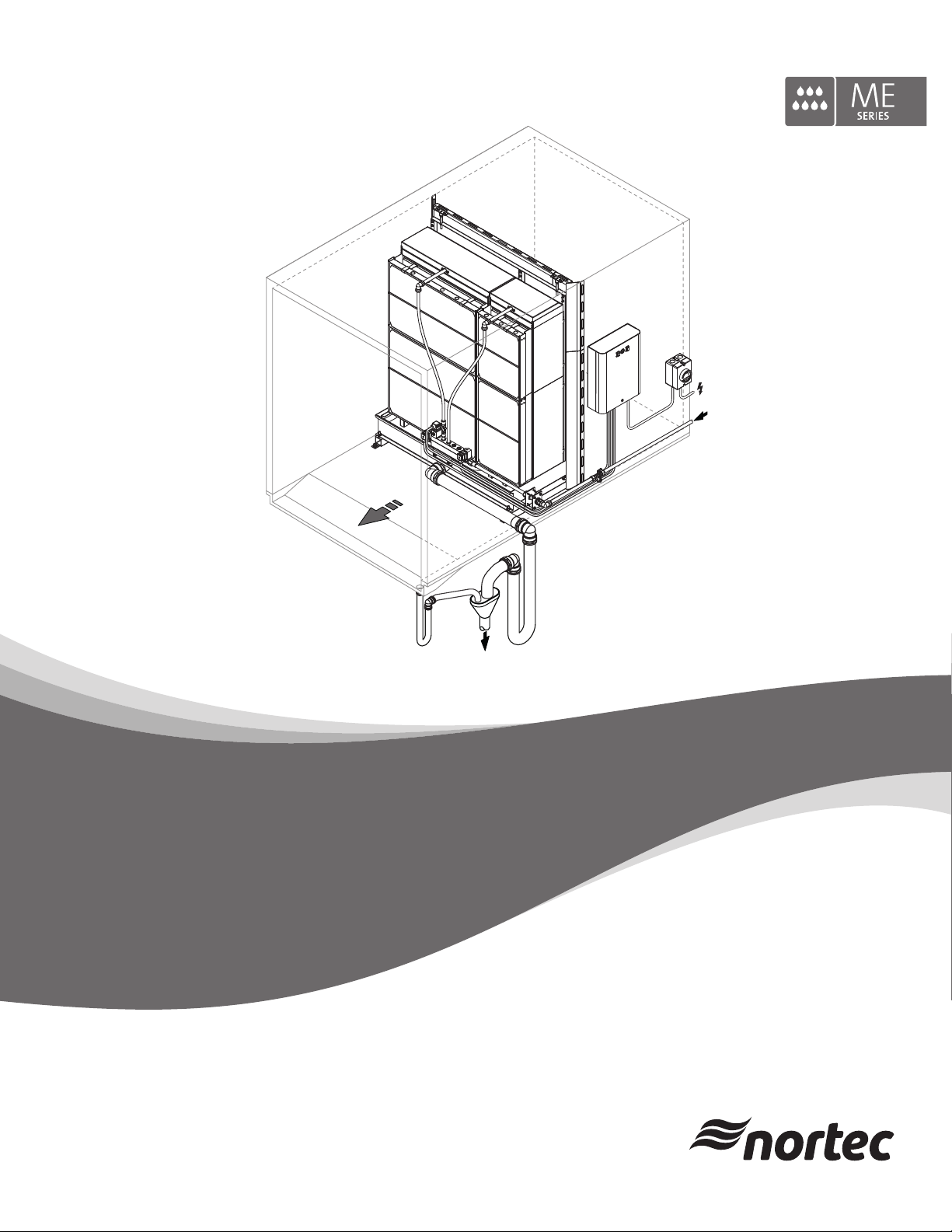
Adiabatic air humidification/air cooling system
Nortec ME Direct Feed
Humidication and Evaporative Cooling
Page 2

Thank you for choosing Nortec
Installation date (MM/DD/YYYY):
Commissioning date (MM/DD/YYYY):
Location ref.:
Model:
Serial number:
Manufacturer
Condair Plc
Artex Avenue, Rustington,
Littlehampton, West Sussex.
BN16 3LN (UK)
TEL: +44(0)1903 850 200
FAX: +44(0)1903 850 345
www.Nortec.co.uk
Proprietary Notice
This document and the information disclosed herein are proprietary data of Condair Plc. Neither this document, nor
the information contained herein shall be reproduced, used, or disclosed to others without the written authorization
of Condair Plc, except to the extent required for installation or maintenance of recipient's equipment.
Liability Notice
Condair Plc does not accept any liability due to incorrect installation or operation of the equipment or due to the
use of parts/components/equipment that are not authorized by Condair Plc.
Copyright Notice
Copyright 2014, Condair Plc All rights reserved.
Technical modications reserved
Page 3

Contents
1 Introduction 5
1.1 General 5
1.2 Notes on the operation manual 5
2 For your safety 7
3 Product Overview 10
3.1 Model overview 10
3.2 Product designation / Which model do you have 11
3.3 Construction of the system components 12
3.3.1 Construction of the evaporative module 12
3.3.2 Construction of the hydraulic manifold 13
3.4 System overviews 14
3.4.1 Typical system Nortec ME Direct Feed (internal installation) 14
3.4.2 Typical system Nortec ME Direct Feed (external installation) 15
4 Operation 18
4.1 Important notes on operation 18
4.2 Initial commissioning 19
4.3 Display and operating elements of Nortec control units 21
4.4 Start up for daily operation 22
4.5 Notes on operation 23
4.5.1 Important notes on operation 23
4.5.2 Recommended regular checks during operation 23
4.6 Decommissioning the system 24
5 Maintenance 25
5.1 Important notes on maintenance 25
5.2 Maintenance Intervals 26
5.3 Maintenance guide 26
5.4 Dismantling and installation of components for maintenance 28
5.4.1 Dismantling and installation of the evaporative module 28
5.5 Consumables Guide 28
5.6 Health and Safety Requirements 29
5.7 Routine Water Sampling and Testing 30
5.8 Cleaning and Disinfection 31
5.9 Cleaning and Disinfection Method Statement 32
6 Fault elimination 33
6.1 Malfunction list 33
6.2 Notes on fault elimination 34
3Contents
Page 4

7 Taking out of service/Disposal 35
7.1 Taking out of service 35
7.2 Disposal/Recycling 35
8 Productspecications 36
8.1 Technical data 36
9 Appendix 37
9.1 Wiring diagram Nortec ME Direct Feed with stage control 37
9.2 Wiring diagram Nortec ME Direct Feed with optional On/Off control unit 38
4 Contents
Page 5

1 Introduction
1.1 General
We thank you for having purchased the NortecMEDirectFeedEvaporativeHumidierandCooler
(Nortec ME Direct Feed for short).
The Nortec ME Direct Feed incorporates the latest technical ad van ces and meets all recognized safety
standards. Nevertheless, improper use of the Nortec ME Direct Feed may result in danger to the user
or third parties and/or impairment of material assets.
To ensure a safe, proper, and economical operation of the Nortec ME Direct Feed, please observe and
comply with all information and safety instructions contained in the present documentation as well as in
the separate documentations of the components installed in the humidication system.
If you have questions after reading this documentation, please contact your Nortec representative. They
will be glad to assist you.
1.2 Notes on the operation manual
Limitation
ThesubjectofthisoperationmanualistheNortecMEDirectFeedEvaporativeHumidierand
Cooler. The various options and accessories are only described insofar as is necessary for proper
operation of the equipment. Further information on options and accessories can be obtained in the
respective instructions.
This operation manual is restricted to the operation, the maintenance and troubleshooting of the
Nortec ME Direct Feed and is meant for welltrainedpersonnelbeingsufcientlyqualiedfortheir
respective work.
Please note, some illustrations in this manual may show options and accessories which may not be
supplied as standard or available in your country. Please check availability and specication details with
your Nortec representative.
The operation manual is supplemented by various separate items of documentation (such as the installation manual), which are included in the delivery as well. Where necessary, appropriate cross-references
are made to these publications in the operation manual.
5Introduction
Page 6
Symbols used in this manual
CAUTION!
The catchword “CAUTION” used in conjunction with the caution symbol in the circle designates notes
in this operation manual that, if neglected, may cause damage and/or malfunction of the unit or
other material assets.
WARNING!
The catchword “WARNING” used in conjunction with the general caution symbol designates safety
and danger notes in this operation manual that, if neglected, may cause injury to persons.
DANGER!
The catchword “DANGER” used in conjunction with the general caution symbol designates safety and
danger notes in this operation manual that, if neglected, may lead to severe injury or even death
of persons.
Safekeeping
Please safeguard this operation manual in a safe place, where it can be immediately accessed. If the
equipment changes hands, the operation manual must be passed on to the new operator.
If the operation manual gets mislaid, please contact your Nortec representative.
Language versions
This operation manual is available in various languages. Please contact your Nortec representative for
information.
6 Introduction
Page 7

2 For your safety
General
Every person working with the Nortec ME Direct Feed must have read and understood the operation
manual of the Nortec ME Direct Feed before carrying out any work.
Knowing and understanding the contents of the operation manual is a basic requirement for protecting
the personnel against any kind of danger, to prevent faulty operation, and to operate the unit safely and
correctly.
All ideograms, signs and markings applied to the components of the Nortec ME Direct Feed must be
observed and kept in readable state.
Qualicationofpersonnel
All work described in this operation manual may only be carried out by specialists who are well
trainedandadequatelyqualiedandareauthorizedbythecustomer.
For safety and warranty reasons any action beyond the scope of this manual must be carried out only
by qualied personnel authorised by the manufacturer.
It is assumed that all persons working with the Nortec ME Direct Feed are familiar and comply with the
appropriate local regulations on work safety and the prevention of accidents.
The Nortec ME Direct Feed may not be used by persons (including children) with reduced physical,
sensory or mental abilities or persons with lacking experience and/or knowledge, unless they are supervised by a person responsible for their safety or they received instructions on how to operate the system.
Children must be supervised to make sure that they do not play with the Nortec ME Direct Feed.
Intended use
The Nortec ME Direct Feed is intended exclusively for
or air ducts within the specied operating conditions. Any other type of application, without the written
consent of the manufacturer, is considered as not conforming with the intended purpose and may lead
to the Nortec ME Direct Feed becoming dangerous.
Operation of the equipment in the intended manner requires that all the information contained in this
operation manual are observed (in particular the safety instructions).
airhumidicationandaircooling inAHU's
7For your safety
Page 8
Danger that may arise from the Nortec ME Direct Feed
DANGER!
Risk of electric shock!
The optional Nortec ME Direct Feed control units contain live mains voltage. Live parts may be
exposed when the control unit is open. Touching live parts may cause severe injury or danger
to life.
Prevention: Before carrying out any work on the Nortec ME Direct Feed switch off the control unit,
disconnect it from the mains via the electrical isolator and secure the electrical isolator in “Off” position
against inadvertent power-up.
DANGER!
Healthriskbecauseofinadequatehygiene!
Inadequately operated and/or poorly maintained evaporative humidication/cooling systems may
endanger health. When inadequately operated and/or poorly maintained micro-organisms (including
the bacterium which causes Legionnaire’s disease) may grow in the evaporative module, the water
tank and the water system of the Nortec ME Direct Feed and may affect the air in the AHU/air duct.
Prevention: the Nortec ME Direct Feed must strictly be operated and maintained in accordance with
this manual.
WARNING!
Some type of evaporative material is manufactured from glass bre. Though this material is not classi-
ed as hazardous, it is recommended that Personal Protection Equipment such as gloves, protective
clothing and eye protection are used during handling to protect the user from bres or dust. If dust is
generated during handling it is recommended that respiratory protection is worn.
Correct lifting and handling
Lifting or handling of components must only be carried out by trained and qualied personnel. Ensure
that the lifting operation has been properly planned and risk assessed, and that all equipment has been
checked by a skilled and competent Health & Safety representative.
It is the customer's responsibility to ensure that operators are trained in handling heavy goods and to
enforce the relevant lifting regulations.
8 For your safety
Page 9

Preventing unsafe operation
If it is suspected that safe operation is no longer possible, then the Nortec ME Direct Feed should
immediately be shut down and secured against accidental power-up according to chapter 4.6 –
Decommissioning the system. This can be the case under the following circumstances:
– if the Nortec ME Direct Feed is damaged
– if the Nortec ME Direct Feed is contaminated
– if the electrical installations are damaged
– if the Nortec ME Direct Feed is no longer operating correctly
– if connections and/or piping are leaking
All persons working with the Nortec ME Direct Feed must report any alterations to the system that may
affect safety to the owner without delay.
Prohibitedmodicationstotheunit
Nomodications must be undertaken on the Nortec ME Direct Feed without the express written
consent of the manufacturer.
For the replacement of defective components use exclusively original accessories and spare parts
available from your Nortec representative.
9For your safety
Page 10
3 Product Overview
3.1 Model overview
The standard version includes the evaporative module (75%, 85 % or 95 % efciency depending
on the cassette type) and a hydraulic manifold without valves (for internal or external installation).
To run the standard version with a On/Off control, the system must be equipped with an On/Off control
unit and the hydraulic manifold must be equipped with a drain valve, a supply valve, and a purge valve
as minimum. All components for extending the standard version to an On/Off control system are available as options (see table below) or must be supplied by the customer.
To run the standard version with a stage control, the system must be equipped with a stage control unit
and the hydraulic manifold must be equipped with a drain valve, a supply valve, a purge valve, and the
appropriate number of stage valves as minimum. All components for extending the standard version to
a stage control system are available as options (see table below) or must be supplied by the customer.
Options On/Off control Stage control
Fibre Media
Composite non particle-releasing glass bre media with anti-microbial impregnation and A2, S2, d0 (UL Class 1) re rating.
Available in 75% (100mm), 85% (150mm) and 95% (200mm) efciencies.
Polyester Media
Robust patented synthetic media with hygroscopic impregnation and DIN
EN53483 Class F1 re rating.
Available in 85% (200mm), 95% (300mm) efciencies.
Droplet Separator
Droplet Catching matrix increasing maximum face velocity limit without droplet carry-over from 3.5 m/s (689 fpm) to 4.5 m/s (886 fpm).
Evaporative module Blanking
Kit to secure Nortec ME and prevent air-bypass within the duct / AHU.
Leak Detection
Provides additional fault indication for the Nortec ME by monitoring for standing water detected in duct / AHU.
Stage valves
Valve kit which facilitates stage control of direct feed systems using customer
controls or the ME Direct Feed Stage Control Unit.
Available in 2, 3, 4 and 5 stage versions.
Inlet, drain and purge valve
Valve kit for customers who wish to create their own basic on/off direct feed
control system.
On/Off control unit
On/Off control unit for simple control of direct feed systems which includes
timed purge function to enhance system hygiene.
Stage control unit
Stage control unit for simple analogue control of direct feed systems which
includes timed purge function to enhance system hygiene.
● ●
● ●
● ●
● ●
● ●
––– ●
● ●
● –––
––– ●
10 Product Overview
Page 11
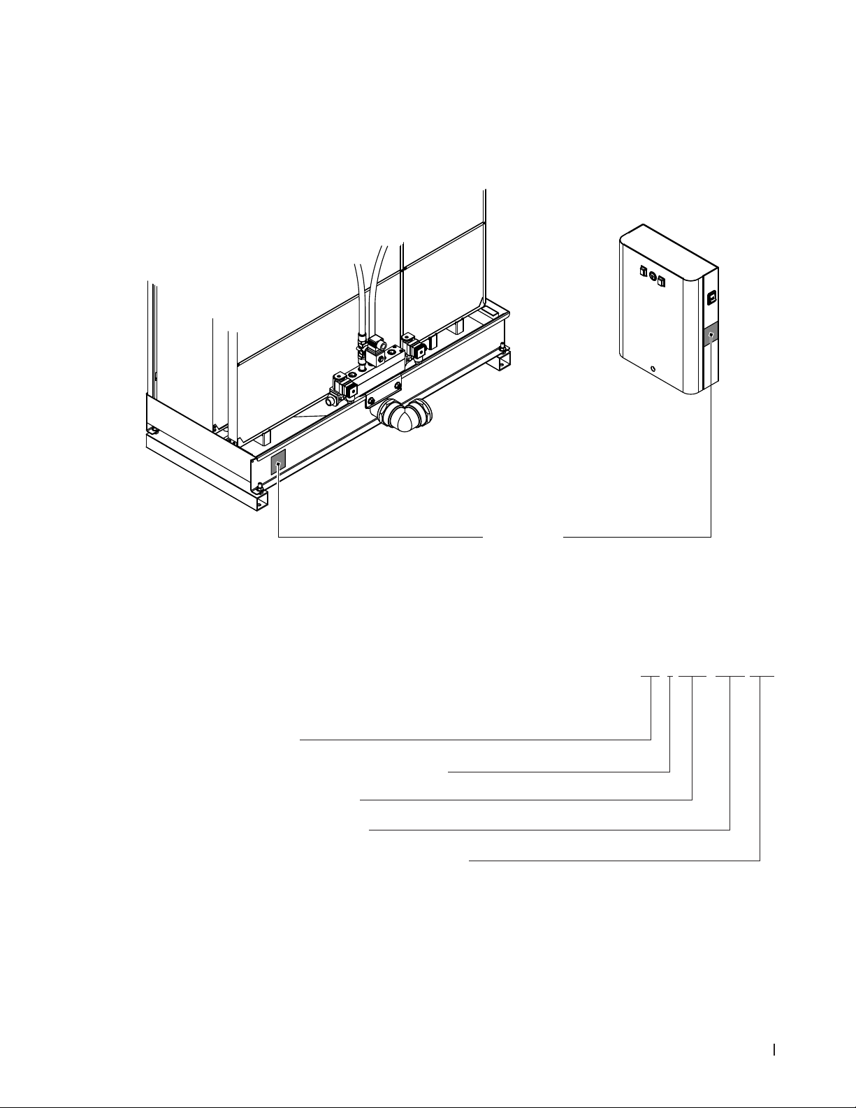
3.2 Product designation / Which model do you have
The product designation and the most important unit data (e.g. serial number, Evaporative module
product key, etc.) are found on the rating plate xed on the left side of the evaporative module and on
the right side of the control unit (if applicable).
Fig. 1: Position of rating plate
Evaporative module product key
Product idencation
ME (media evaporator)
Product version (consecutive version number):
Width evaporative module in mm
Height evaporative module in mm
Material type and efciency evaporative cassettes:
F75= Glass bre 75 %
F85= Glass bre 85 %
F95= Glass bre 95 %
P85= Polyester 85 %
P95= Polyester 95 %
Rating Plate
Example:
ME-1-0900-1125-F95
11Product Overview
Page 12
3.3 Construction of the system components
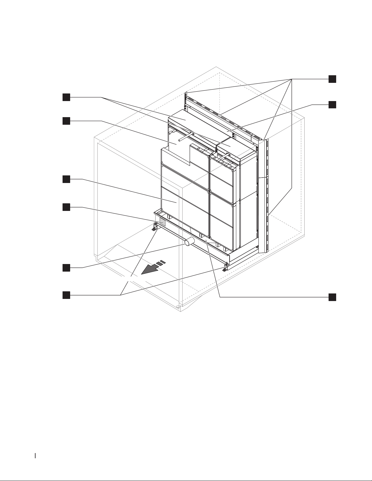
3.3.1 Construction of the evaporative module
6
5
4
3
7
8
2
Air ow direction
1
1 Upstands
2 Tank connector ø54 mm (2.125")
3 Rating plate
4 Droplet separator, mandatory for face velocity
>3.5 m/s (>689 fpm)
Fig. 2: Construction of the evaporative module
9
5 Evaporative cassettes (F75, F85, F95, P85 or P95)
6 Distribution heads
7 Blanking plates (option)
8 Mounting frame for evaporative cassettes
9 Water tank
12 Product Overview
Page 13

3.3.2 Construction of the hydraulic manifold
9
8
7
2
1
6
5
4
3
10
1 Fixing bracket
2 Drain valve (option or supplied by others)
3 Supply valve (option or supplied by others)
4 Connector stage 5
5 Connector stage 3
6 Connector stage 1
7 Connector stage 2
8 Connector stage 4
9 Stage valve 2 (option or supplied by others)
10 Purge valve (option or supplied by others)
Fig. 3: Construction of the hydraulic manifold (gure shows layout for 2-stage control)
8
7
2
6
5
4
9
3
1
1 Fixing bracket
2 Drain valve (option or supplied by others)
3 Supply valve (option or supplied by others)
4 Connector stage 5
5 Connector stage 3
6 Connector stage 1
7 Connector stage 2
8 Connector stage 4
9 Purge valve (option or supplied by others)
Fig. 4: Construction of the hydraulic manifold (gure shows layout for On/Off control)
13Product Overview
Page 14

3.4 System overviews
3.4.1 Typical system Nortec ME Direct Feed (internal installation)
Blanking plates
Drain valve
Hydraulic manifold (with
optional supply valve, drain
valve and stage valve)
Air ow direction
AHU drain
with trap
Evaporative module
Stage valve
Supply valve
Water drain line
Control unit
Purge valve
Electrical
isolator
Water supply line
Shut-off valve
(not supplied)
Fig. 5: Typical system Nortec ME Direct Feed (internal installation with optional valves)
14 Product Overview
Page 15

3.4.2 Typical system Nortec ME Direct Feed (external installation)
Blanking plates
Air ow direction
AHU drain
with trap
Evaporative module
Stage valve
Drain valve
Control unit
Supply valve
Water drain line
Electrical
isolator
Water supply line
Shut-off valve
(not supplied)
Purge valve
Hydraulic manifold (with
optional supply valve, drain
valve and stage valve)
Fig. 6: Typical installation Nortec ME Direct Feed (external installation with optional valves)
15Product Overview
Page 16

Schematicowdiagram
Evap-
orative cassettes
Water tank
Stage valve
(optional)
Drain solenoid
valve (NO)
2 1 3 54
AHU
Hydraulic manifold
Inlet solenoid
valve (NC)
Drain trap
(building side)
Tundish
(building side)
Shut-off
valve with
strainer
Purge solenoid
valve (NC)
Fig. 7: Schematic ow diagram Nortec ME Direct Feed System (internally mounted)
AHU
Evaporative cassettes
Water tank
Drain trap
(building side)
(building side)
Tundish
Stage valve
(optional)
2 1 3 54
Drain solenoid
valve (NO)
Hydraulic manifold
Tundish
(building side)
Inlet solenoid
valve (NC)
Shut-off valve
with strainer
Purge solenoid
valve (NC)
Fig. 8: Schematic ow diagram Nortec ME Direct Feed System (externally mounted)
16 Product Overview
Page 17

Functional description
As standard the Nortec ME Direct Feed is operated with On/Off control (requires a drain and a supply
valve fitted to the hydraulic manifold (both valves available as options) and a customer supplied On/Off
control or the optional direct feed On/Off control unit).
Equipped with the optional stage valves and the optional direct feed stage control unit, stage control
can be established.
In case of a humidication/cooling request with standard On/Off control the drain solenoid valve (NO)
closes and the inlet solenoid valve (NC) opens and the water ows to the distribution header above the
evaporative cassettes.
In case of a humidication/cooling request with optional stage control unit the drain solenoid valve (NO)
closes and the inlet solenoid valve (NC) opens. Depending on the demand signal and the evaporative
module size additionally stage valve two, three, four and ve open to supply water to the distribution
header of the corresponding evaporative cassettes bank.
The distribution pipes inside the distribution header evenly supply the water to the entire surface of the
evaporative cassettes where it ows down and humidies the air owing through the evaporative cassette
matrix. The excess water not used for humidication ows to the water tank and then directly to the drain.
Both optional direct feed control units (On/Off control unit and stage control unit) support time based
ushing of the water supply line once a purge valve (available as option) is tted in the supply line. Every
20 hours the water supply line is ushed via the purge valve to prevent water stagnation in the water
supply line which can lead to the grow of micro-organisms in the water supply line.
17Product Overview
Page 18

4 Operation
4.1 Important notes on operation
Qualicationofpersonnel
The Nortec ME Direct Feed must be commissioned and op erated only by personnel familiar with the
system and adequately qualied for the respective tasks. It is the owner’s responsibility to verify proper
qualication of the operating personnel.
General notes
The instructions and details regarding commissioning and operation must be followed and upheld.
The initial commissioning of the Nortec ME Direct Feed requires appropriately trained technical personnel. It is strongly recommended that your Nortec representative commissions your system. Part of this
initial commissioning process may include a disinfection of the water tank and the evaporative cassettes.
Please read this document in full before commencing any work.
Please pay attention to local regulations regarding working at heights and electrical work.
Safety and hygiene
DANGER!
The Nortec ME Direct Feed must be operated in accordance with this manual. Failure to do so
could result in contamination that might cause Legionnaires’ disease, which can be fatal
WARNING!
TheNortecMEDirectFeedsystemequippedwithanoptionalNortecMEDirectFeedcontrol
unit should not be electrically isolated for periods exceeding 24 hours as automatic drain and
purge cycles will be disabled.
18 Operation
Page 19

4.2 Initial commissioning
The initial commissioning of the Nortec ME Direct Feed requires appropriately trained technical personnel. We strongly recommend that your Nortec representative commissions your system.
Inspections
Prior to initial commissioning the complete system must be inspected for correct execution of the installations. Proceed as follows:
1. Switch off AHU.
2. Evaporative module installation: Check correct selection of evaporative module on rating plate if
multiple units on site. Check that the evaporative module has been installed level in all planes with
secure blanking plates to prevent air bypass. Check that there is sufcient access for cassette removal during maintenance. Ensure assembly is securely xed, and that there is no visible damage.
Check that the evaporative module is installed in a waterproof section. Check evaporative module
(including tank) is free of dirt/ debris and clean as necessary.
3. Control unit installation: Check that the control unit is mounted in a convenient dry location
4. Supply water Installation: Ensure the water system in the building has been subject to a Risk Assessment. The Nortec ME Direct Feed must be connected to a clean, wholesome mains water
supply. It is the responsibility of the user to ensure that the water system complies with local regulations and bylaws, particularly those for the control of Legionella microbes. The use of mains water
fed tanks and reservoirs is only permitted as part of a managed water treatment system. Check that
the evaporative module has a feed water supply in excess of 2 bar (29 psi) connected to the supplied approved lling hose. Ensure that any hygiene options have been correctly installed. Check
all joints and ttings for leaks.
5. Drain installation: Check that the drain line is made according to the corresponding instructions
given in the installation manual. Ensure the drain line is connected to the main building drain and
that drain pipework is trapped to a suitable level for the applicable working duct pressure. Check all
joints and ttings. Ensure that the drain connection includes an air gap.
6. Distribution pipework: Check all water distribution pipework between the hydraulic manifold and
the distribution headers are securely tted.
7. Electrical wiring: Check all electrical connections with reference to the corresponding wiring diagram
in this manual. Check that a 100...240V / 10A single phase supply is connected to the control unit.
Ensure that this power supply is isolated with an electrical isolator within 1 m (39") of the control unit.
Note: For systems equipped with a custom control unit please refer to the corresponding manual.
8. Optional controls: Check that appropriate controls connections have been made to the control unit.
Refer to the controls wiring section of the installation manual.
9. Flushwatersupplyandtestsupplywaterquality: Disconnect water supply pipe from connector
on the hydraulic manifold. Fix hose to free end of supply pipe and lead hose to a drain. Carefully
ush supply pipe a suitable amount of time without creating splashing or aerosols.
Take a water quality sample to ensure that supply water meets the requirements specied in the
water quality guide. The sample should be tested using a dip slide to indicate the total number of
colony forming units per ml (cfu/ml). Generally, levels of 1x10
3
cfu/ml may be considered acceptable
for this type of humidier provided the species of microbes and/or fungi involved are themselves not
considered to be harmful. If you are unsure of the quality of your water please consult your Nortec
distributor for advice.
Then reconnect the water supply pipe to the supply connector on the hydraulic manifold.
19Operation
Page 20

10. Perform pressure test: Turn on water supply and check for leaks. Ensure double check valve is
installed correctly.
After the system has been inspected and found correct proceed with the initial commissioning:
1. Ensure AHU is switched off.
2. If evaporative cassettes have become dirty or damp prior to commissioning, then disinfect the system
as described in sections 5.3 and 5.9 of this manual.
3. Validate control requirements and enable a full demand to unit. If Nortec control unit is used, check
for correct connections and operation when switched on.
4. If using the Nortec control unit the system will purge the water supply line, when rst switched on.
Normal operation will commence after three minutes.
5. Flush water through all cassettes (ensure all stages are operating if stage control option).
6. Check water is owing to drain with no leakage.
7. Allow system to ush with full demand until water is clean.
8. Check all components are operating correctly (including any option kits i.e. inlet valve, drain valve,
purge valve, stage valves).
9. Test correct ow of water to distribution header.
10. Switch on fan of AHU and test operation with fans running and validate air conditions against the
design data.
11. Test controls set up and ensure correct set points. If drain or automatic ush options are installed,
set up suitable cycles.
12. Switch off AHU.
13. Wipe tank clean (including section under cassettes).
14. If commissioning has not been completed by an approved Nortec representative, it is recommended
that records are kept of commissioning date and software settings.
15. Demonstrate system to customer and highlight hygiene and maintenance requirements.
16. Raise any installation concerns.
17. Issue commissioning documentation.
The system is now ready for normal operation.
20 Operation
Page 21

4.3 Display and operating elements of Nortec control units
1 <Control unit On/Off> switch (located on the
right side of the control unit)
Note: with this switch you can switch on and off
the control unit. If the control unit is switched off
all functions (including hygiene functions) of the
Nortec ME Control are deactivated.
2 Electrical isolator
Note: the electrical isolator (supplied by the customer) must be installed in the mains supply line!
3 Status LED green: Nortec ME Direct Feed is
humidifying/cooling
4 <Humdication/CoolingOn/Off> switch
5 Status LED white: Unit switched On
Fig. 9: Display and operating elements Nortec control units (option)
DANGER!
Risk of electric shock!
Since mains supply to the control unit is not interrupted by switching off the
<Humdication/Cooling
On/Off> switch and there is still mains voltage inside the control unit even when you switch off the
<Control unit On/Off> switch too, the electrical isolator must be switched off before open the
control unit.
21Operation
Page 22

4.4 Start up for daily operation
It is assumed that initial commissioning has been carried out properly by appropriately trained technical
personnel.
The following description outlines the start up procedure for daily operation for systems equipped with an
optional Nortec ME Direct Feed control unit. For systems equipped with a control unit of another brand
please refer to the operating instructions of the corresponding control unit.
Proceed as follows to prepare the Nortec ME Direct Feed for operation:
1. Switch off AHU.
2. Examine the Nortec ME Direct Feed for possible damage. Ensure tank is empty.
DANGER!
Damaged systems or systems with damaged components or installation may present danger to
human life or cause severe damage to material assets.
Damaged systems and/or systems with damaged or faulty installation must not be operated.
3. If Nortec ME Direct Feed has been disconnected from the mains for more than 48 hours:
• Close shut-off valve in the water supply line.
• Disconnect water supply line from the connector on the hydraulic manifold. Caution should be
taken to ensure no splashing is created.
• Connect hose to the water supply line and lead the open end into open tundish outside the AHU.
• Open shut-off valve in the water supply line and ush water supply line an appropriate length of
time. Then, close shut-off valve again, remove hose and reconnect supply line to the connector
on the hydraulic manifold.
4. Make sure the front panel of the control unit is mounted and xed with the retaining screw.
5. Close doors of AHU if open, then switch on AHU if switched off.
6. Open shut-off valve in the water supply line.
7. Switch on the electrical isolator in the mains supply to the control unit.
8. Switch <Control unit On/Off> and <Humdication/CoolingOn/Off>switch on the control unit to
“On” (systems equipped with a Nortec control unit only).
The Nortec ME Direct Feed is now ready for operation.
22 Operation
Page 23

4.5 Notes on operation
4.5.1 Important notes on operation
If your system is equipped with the optional Nortec control unit and the optional purge valve, the water
supply line is purged every 20 hours for approximately 3 minutes in order to ush water supply line.
The Nortec stage control unit will also drain the hoses that supply water to the distribution header during these 3 minutes.
4.5.2 Recommended regular checks during operation
During operation the Nortec ME Control has to be checked periodically in accordance with the table below.
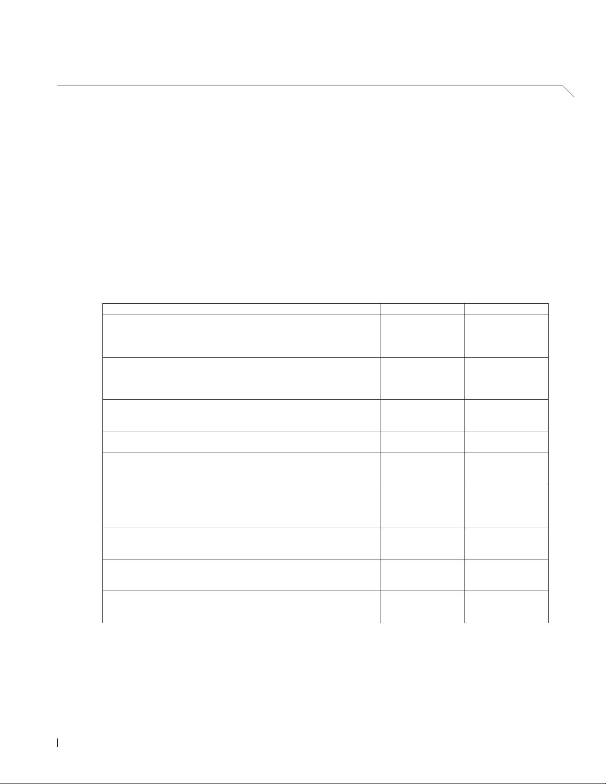
Operations Checks Daily Weekly Monthly Quarterly
Monitor humidity/temperature control
Check for any low humidity/temperature concerns
Check any alarms on BMS
Visible check for:
No water leakage (air on and air off side)
–
– system components for correct xing and any da-
mage
– electric installation for any damage.
Matrix media is saturated (relative to demand signal)
Condition of tanks and air on matrix is clean
Inspect and determine replacement frequency of sediment lter
Condition of tanks are clean (clean as required)
If the checks reveal any irregularities (e.g. leakage, error indication) or any damaged components take
the Nortec ME Control out of operation as described in chapter 4.6 – Decommissioning the system.
Then, have the malfunction eliminated or the damaged component replaced by a well trained specialist
or a service technician from your Nortec representative.
23Operation
Page 24

4.6 Decommissioning the system
In order to decommission the Nortec ME Direct Feed (e.g. to perform maintenance works, to eliminate
a malfunction, etc.) perform the following steps:
1. Close the shut-off valve in the water supply line.
2. Switch off control unit: switch off <Humdication/Cooling On/Off> and <Control unit On/Off>
switch on the control unit (only with Nortec control units).
Note: if your system is equipped with a control unit other than Nortec, please refer to the corresponding manual for switching off the control unit.
5. Disconnect control unit from the mains: switch off the electrical isolator in the mains supply to
the control unit and secure switch in “Off” position against accidentally being switched on, or clearly
mark the switch.
6. Let the fan of the ventilation system run until the evaporative module is dry.
7. If work has to be carried out on the evaporative module or the hydraulic manifold mounted inside
the duct, switch off the AHU and secure the system against accidentally being switched on.
Important Notes!
– This applies only for systems equipped with the optional Nortec control unit and the optional purge
valve: for reasons of hygiene, we recommend that the control unit should be left powered on even if
the Nortec ME Direct Feed is not being used for a longer period of time. Only the <Humdication/
Cooling On/Off> switch should be switched off. This keeps the hygiene functions (e.g. periodical
ushing of water supply pipe) active and hence the build-up of germs is opposed.
– If the Nortec ME Direct Feed is isolated from the mains for prolonged periods, water stagna-
tion might occur in supply pipework and microbial contamination result, therefore the system,
including any storage tanks or vessels should be drained and left dry. Before putting the system
back into operation, a full risk assessment should be undertaken to ensure safe operation, with
particular attention paid to water supply quality. Additionally a complete system service has to
be performed prior to putting the system back in operation.
24 Operation
Page 25

5 Maintenance
5.1 Important notes on maintenance
Qualicationofpersonnel
All maintenance work must be carried out only by wellqualiedandtrainedpersonnelauthorisedby
the owner. It is the owner’s responsibility to verify proper qualication of the personnel.
General notes
The instructions and details for maintenance work must be followed and upheld. Only carry out the
maintenance work described in this documentation.
The Nortec ME Direct Feed must be maintained in the prescribed intervals, the cleaning work must be
carried out correctly.
Only use original spare parts from your Nortec representative to replace defective parts or parts which
have elapsed their lifetime.
Safety and hygiene
Some maintenance work requires removal of the unit cover. Please note the following:
DANGER!
Dangerofelectrichazard!
Before carrying out any maintenance work take the Nortec ME Direct Feed out of operation as
described in chapter 4.6 – Decommissioning the system and secure the system against inadvertent power-up. In addition take AHU out of operation as described in the operations instructions of the
AHU and secure the AHU against inadvertent power-up.
CAUTION!
The electronic components inside the optional Nortec control unit are very sensitive to electrostatic
discharge.
Prevention: Before carrying out any maintenance work to the electrical or electronic equipment of
the control unit, appropriate measures must be taken to protect the respective components against
damage caused by electrostatic discharge (ESD protection).
DANGER!
Healthriskbyinadequatemaintenance!
Inadequatelyoperatedand/orpoorlymaintainedadiabatichumidication/coolingsystemsmay
endanger health. When inadequately operated and/or poorly maintained, micro-organisms
(including the bacterium which causes Legionnaire’s disease) may grow in the water system
andintheareaofthehumidicationunitandmayaffecttheairintheAHU/airduct.
Prevention: the adiabatic air humidication /air cooling system Nortec ME must be correctly operated
as described in chapter 4 – Operation, and must be correctly maintained and cleaned in the prescribed
intervals as described in chapter 5 – Maintenance.
25Maintenance
Page 26

5.2 Maintenance Intervals
In order to maintain operational safety and hygienic demands the Nortec ME Direct Feed must be serviced
at regular intervals. The time interval for the complete system service is to be adapted to the operating
conditions. The hygiene status depends mainly on the quality of the humidier water but also on the
adherence to the exchange intervals of the upstream air lter, the air velocity and the micro-biological
and chemical composition of the supply air. Therefore the service intervals must be determined for each
system separately.
The interval time for a complete system service is to be determined at commissioning. A typical interval
time is 2000 hours of operation.
Depending on the encountered hygiene status when performing a complete system service the interval
time must be decreased or increased.
In any case the Nortec ME Direct Feed should receive a complete service at least once annually.
Note: We recommend to perform a minor service between two complete system service.
5.3 Maintenance guide
The Nortec ME unit will form part or your hot and cold water system and as such require you to undertake
certain duties with regards to local regulations and bylaws concerning the control of Legionella microbes
in water systems. Your water sampling / testing and disinfection regime must be based on results of a
site specic risk assessment.
If any further assistance is required or you are interested in a planned maintenance quote, please contact
your Nortec distributor.
Note: routine water sampling and testing is not included as part of a Nortec service contract.
Please note that the information given in the table below is only to act as a guide which shows the work
to be carried out on “Minor Service” and “Complete System Service”.
Correct maintenance is vital to ensure optimum output, reliability and safety.
Operations Minor
Service
Replace inlet water lter if applicable Yes Yes
Check all solenoid valves Yes Yes
Clean all solenoid valves ––– Yes
Replace purge valve ow restrictor (if applicable) ––– Yes
Check all hoses and connectors Yes Yes
Check ow restrictors in hydraulic manifold ––– Yes
Clean inlet valve strainer ––– Ye s
Replace all feed hose ––– Yes
Check distribution headers Yes Yes
Clean distribution headers ––– Yes
Clean front section of tank Yes Yes
Check droplet separator (if applicable) and evaporator cassettes in suitable condition
Yes Yes
Complete
System Service
26 Maintenance
Page 27

Operations Minor
Service
Lightly brush evaporator cassettes if necessary, replace if heavily soiled ––– Yes
Remove evaporator cassettes and clean all sections of tank and frame
structure
Check and secure frame structure and seal ––– Yes
Check all media for full saturation Yes Yes
Measure ow rates to distribution headers ––– Yes
Check and secure all electrical connections Yes Ye s
Check overall installation for leaks and damage Yes Yes
Check any options as per relevant documentation Yes Yes
Complete disinfection as described in this manual Yes Yes
Check safety interlock and humidity/temperature control devices (if applicable)
Check air velocity at face of evaporative cassettes matrix ––– Yes
Update service log book Yes Yes
––– Yes
––– Yes
Complete
System Service
27Maintenance
Page 28

5.4 Dismantling and installation of components for maintenance
5.4.1 Dismantling and installation of the evaporative module
1. Take the Nortec ME Direct Feed out of operation as described in chapter 4.6 – Decommissioning
the system and allow to drain and dry.
2. Switch the AHU off, and isolate the power and water supply to the AHU.
3. Disconnect distribution hoses from the connectors on the distribution heads, the wall feed-throughs
(if applicable) and the hydraulic manifold.
4. Remove droplet separator boxes (column by column):
• Remove upper separator brackets.
• Remove bank of separator boxes.
• Remove lower separator brackets.
5. Remove evaporative cassettes (column by column):
• Push box upwards and remove.
6. Remove distribution headers assemblies from topmost evaporative cassettes:
• Remove plastic rivets xing the distribution header assembly to the evaporative cassette.
• Carefully lift off the distribution header assembly.
7. Remove the cross bar (remember position).
Clean dismantled components, water tank, frame structure, blanking plates and air duct as described in
chapter 5.3 – Maintenance guide. If all components have been cleaned and dried, assemble the evaporative module in the reverse dismantling order. Replace any defective components with new ones.
5.5 Consumables Guide
Common consumables
Description StandardFrequency(month)
DISIFIN XL 1
Disinfection chemical (sourced locally) 6
Descaling chemical (sourced locally) as required
Inlet ow restrictor 24
Distribution header feed hose 24
Evaporative matrix cassette
Wholesome mains water
–
– RO water
36 - 60
60 - 84 +
28 Maintenance
Page 29

Option consumables
Description StandardFrequency(month)
PureFlo Ag+ sediment lter 6
PureFlo Ag+ antimicrobial lter 12
Contact your Nortec distributor for consumables list/order codes.
To help us ensure that the correct spares parts are sent, please conrm your unit serial and model
number with your order.
5.6 HealthandSafetyRequirements
In accordance with local regulations, users must take water samples for Legionella analysis. Samples
should be taken from the same places as described in chapter 5.7 – Routine Water Sampling and Test-
ing, and the analysis carried out by an accredited laboratory which is part of an appropriately certied
Legionella testing scheme. In the event that the Legionella content exceeds 102 cfu/l, the humidier
should be switched off and specialist advice sought regarding its disinfection.
1. If biolm (a slimy or gel-like deposit when wet, which might be dry and crisp in a dry system) is found
during any inspection of the humidier or water system, the humidier MUST be switched off and
not put back into operation until the system has been taken apart, scrubbed and thoroughly cleaned
with a suitable biocide with biolm penetrating qualities such as 50 ppm chlorine dioxide solution.
This work should only be carried out by fully trained specialist organisations or individuals.
2. The optional Nortec ME Direct Feed control unit must be left powered on to allow automatic
ushingandcleaningcyclestooccur. If the optional Nortec ME Direct Feed control unit is powered
off for prolonged periods, water stagnation might occur and contamination result, so the system,
including any storage tanks or vessels should be drained and left dry. Before putting the system
back into service, the water pipework supplying the Nortec ME Direct Feed should be purged care-
fully, avoiding the creation of aerosols by splashing, and a water sample should be taken to ensure
cleanliness. In the event that the humidier pipework contains any residual water or has remained
damp, and the temperature exceeded 20 °C (68°F), the Nortec ME Direct Feed should be disinfected
using an appropriate solution.
Contact your Nortec representative for advice on water sampling and analysis, disinfection of systems,
service and maintenance.
29Maintenance
Page 30

5.7 Routine Water Sampling and Testing
Hygiene
Your attention is drawn to local regulations and bylaws regarding the control of Legionellosis in water
systems. If inadequately maintained, water systems, of which any humidier is a part, can support the
growth of micro-organisms, including the bacterium that causes Legionnaires’ disease. Nortec Humid-
ity Ltd. has considered all aspects of this equipment to reduce as far as possible the risk of Legionnaires’
disease and other similar conditions, but it is important that users are aware of their responsibilities under
local regulations in reducing the risk of Legionellosis.
To prevent the growth of Legionella, users are required to:
1. Carry out a risk assessment of the water system using a competent person, and implement an appropriate monitoring and control regime.
2. Avoid water temperatures which favour the growth of Legionella.
3. Avoid water stagnation.
4. Clean and disinfect the system in accordance with local regulations and bylaws, and the instructions
in this manual.
5. The Nortec ME Direct Feed system MUST be connected to a clean, wholesome mains water supply and it is recommended that the supply water is chlorinated. It is the responsibility of the user to
ensure that the water system complies with local regulations and bylaws, particularly those for the
control of Legionella microbes. The use of mains water fed tanks and reservoirs is only permitted
as part of a managed water treatment system.
On commissioning and at regular intervals thereafter, test for possible water contamination using Dipslides.
Take samples from the water supply, the evaporative cassettes and from the tank. Check for biolm.
The Dipslides should be incubated for 2 days at 30°C (86°F).
3
1. If the microbial count from the tank exceeds 10
cfu/ml, the system should be turned off, any biolm
scrubbed clean and then disinfected using a 50 ppm chlorine solution for one hour before being put
back into use.
3
2. If the microbial count in the water supply to the evaporative module exceeds 10
cfu/ml, this suggests contamination of the water system within the building. The system should be turned off and
you should seek specialist advice on cleaning your water supply.
3. If the water temperature anywhere in the system regularly exceeds 20°C, (68°F) increase the frequency of water sampling. The frequency may be reduced if successive tests show a consistent
3
level below 10
cfu/ml.
30 Maintenance
Page 31

5.8 Cleaning and Disinfection
Before commencing cleaning and disinfection:
For systems in operation or where the water quality or air quality is poor, it is recommended to dismantle and scrub the system clean, to carry out a disinfection of all parts of the evaporative module with
a minimum of 50ppm chlorine or an appropriate disinfection solution. Please refer to the cleaning and
disinfection and method statement section to ensure that the relevant chemicals, equipment and Personal
Protective Equipment are available to carry out disinfection.
1. Risk assess the situation. This should include but is not limited to observance of local regulations
and the use of PPE, working from heights and ensuring a full understanding of the Nortec ME Direct
Feed.
2. Coordinate with relevant responsible persons.
3. Check records (i.e sample results of microbiological control) for system history.
4. If possible, disinfection should be carried out when the building is unoccupied, with air ow off.
Evaporative humidiers must be regularly cleaned and maintained, to prevent contamination especially
in industrial environments.
All surfaces requiring disinfection or cleaning must be in contact with the appropriate concentration of
disinfection solution for the correct contact period. The method statement for disinfection may need to
be adapted depending on the layout of the humidier pipework. Additional procedures will be required
for supply water system pipework or water treatment systems prior to the humidier.
Nortec Humidity Ltd. recommends that routine disinfection should take place in the following situations:
• At six monthly intervals as part of the maintenance regime.
• If the system or part of it has been shutdown and/or substantially altered creating a risk of contamination.
• During or following any increase of bacterial activity (as per recommendations in chapter 5.7 – Rou-
tine Water Sampling and Testing) or outbreak or suspected outbreak of Legionellosis.
RecommendedDisinfectionEquipment
– Disinfection solution in accordance with manufacturers guidelines.
– Disinfection neutraliser (only if necessary).
– Disinfection solution test kit (to measure strength).
– Bucket of fresh water.
– Cleaning equipment.
– Mixing vessel / Measuring container.
– Risk assessment / test record sheets. Appropriate report/record
– Standard tools
– Appropriate PPE
– COSHH risk assessment / MSDS
31Maintenance
Page 32

5.9 Cleaning and Disinfection Method Statement
Step 1 - Refer to the Risk Assessment
• Refer to the Manufacturers instructions and safety advice.
• Ensure the area is well ventilated.
• Ensure the Nortec ME system is OFF and isolated from external controls.
• If the unit is already in operation there is low risks, check for correct operation before cleaning
and dismantling.
Note: if there are concerns over condition of unit, drain unit, ush water supply, and disinfect
tank before starting cleaning work.
• Drain system, dismantle unit and scrub tank fully. For complete disinfection remove droplet separa-
tor banks (if applicable) and the evaporative cassettes to allow a full clean (refer to maintenance
section).
• Consider appropriate maintenance requirements at this time including parts replacement i.e.
replacing distribution hoses to ensure that these are also disinfected.
Step 2 - Mix Disinfection Solution
• Prepare a vessel into whom the evaporative cassettes and droplet separator banks can be placed
for disinfection
• Mix disinfection solution following the manufacturers instructions and in the required amount.
• Note: Solution loses strength over time and the solution may need to be increased through the
process or the disinfection process may need to be repeated.
Step 3 - Disinfection
• Place evaporative cassettes and droplet separator banks into the vessel with the disinfection
solution and leave them in the solution for the correct amount of time.
• Note the strengths of the disinfection solution at 15 minute intervals and adjust solution strength
as required.
• Wash tank, tank frame and AHU section with a cloth soaked with disinfection solution.
• After disinfection rinse all parts thoroughly with wholesome water to remove any disinfection
chemicals. Then, dry or let dry all components.
Step4-Neutralisethedisinfectionsolution–ifrequiredbasedonchemicalused
WARNING!
If a neutralising solution is required, always ensure that the neutralising solution is used in accordance with the manufacturer’s guidance. Failure to follow the manufacturer’s guidance with regard
to neutralising the disinfection chemical may present a risk to health.
• Mix neutralising agent as per manufacturers instructions.
• Measure the strength as per MSDS until the disinfection solution is down to desired strength.
Step 5 - Drain neutralised disinfection solution
• Drain neutralised disinfection solution into appropriate drain (depending on Risk Assessment) .
• Always leave work area clean, dry and tidy.
Step 6 - Re-assemble evaporative module and Re-start the Nortec ME system
If in doubt always contact your Nortec distributor.
32 Maintenance
• Re-assemble evaporative module and restart ME system. Refer to the corresponding section.
Page 33

6 Fault elimination
Important! Most operational malfunctions are not caused by faulty equipment but rather by improper
installation or disregarding of planning guidelines. Therefore, a complete fault diagnosis always involves
a thorough examination of the entire system. Often, the installations have not been properly executed,
or the fault lies with the humidity control system.
6.1 Malfunction list
Malfunction Cause Remedy
Residual water in the section
of the duct downstream of the
evaporative module.
Humidity/cooling demand
present however the Nortec ME
Direct Feed does not humidify.
Maximum humidication/cooling
capacity is not reached.
Face velocity is too high. Systems
without droplet separator max
3.5 m/s (689 fpm), systems with
a droplet separator max. 4.5 m/s
(886 fpm).
Water tank, water piping or hydraulic
manifold is leaking.
Water ow to media too high. Check/replace ow restrictors in the
Evaporative cassettes have become
blocked with minerals.
Uneven or non laminar air ow. Check design conditions of AHU.
Air on temperature is too low. Check design conditions of AHU. and
Shut-off valve in the water supply
line closed.
Site control are not correct. Prove controls and control module.
Insufcient water supply capacity. Check water supply, increase water
Install droplet separator or reduce air
velocity in the duct.
Check/seal water tank, water piping
and hydraulic manifold.
hydraulic manifold.
Check set up, replace evaporative
cassettes, perform system service.
Install perforated plate on the air
supply side.
increase temperature.
Open shut-off valve.
pressure.
Evaporative cassettes have become
blocked with minerals.
Check set up, replace evaporative
cassettes, perform system service.
33Fault elimination
Page 34

6.2 Notes on fault elimination
– For the elimination of faults set the Nortec ME Direct Feed out of operation as described in chapter
4.6 – Decommissioning the system, disconnect control unit from the mains and close shut-off valve
in the water supply line.
DANGER!
Make sure the control unit is separated from the mains (check with voltage detector) and the shutoff valve in the water supply line is closed.
– The elimination of faults must be carried out by qualied and well trained professionals only.
Malfunctions relating to the electrical installation must be repaired by authorized personnel (e.g.
licensed electrician) or by your Nortec representative’s service technician only.
CAUTION!
Electronic components are very sensitive to electrostatic discharge. When carrying out repairs
to the control unit, appropriate measures (ESD-protection) must be taken to prevent damage to
electronic components.
– Repair work and the replacement of faulty components must be carried out by your Nortec repre-
sentative’s service technician only!
34 Fault elimination
Page 35

7 Taking out of service/Disposal
7.1 Taking out of service
If the Nortec ME Direct Feed must be replaced or if the humidication system is not needed any more,
proceed as follows:
1. Take the Nortec ME Direct Feed out of operation as described in chapter 4.6 – Decommissioning
the system.
2. Have the system components unmounted by a qualied service technician.
7.2 Disposal/Recycling
Components not used any more must not be disposed of in the domestic waste. Please dispose of the
individual components in accordance with local regulations at the authorised collecting point.
If you have any questions, please contact the responsible authority or your local Nortec representative.
Thank you for your contribution to environmental protection.
35Taking out of service/Disposal
Page 36

8 Productspecications
8.1 Technical data
With optional
Supply voltage optional On/Off and stage control unit 100...240 VAC/50...60 Hz
Power consumption
Control signals On/Off 0..10 VDC
Control accuracy Control accuracy depends on air conditions, control
Max. admissible matrix face velocity 3.5 m/s (689 fpm)
Water supply ø15mm (0.625") push-t connector
Water drain (outside diameter) ø 54 mm (2.125")
Admissible water supply pressure 2...5 bar (29...72.5 psi)
Admissible water temperature 5...20 °C (41...68 °F)
Water quality Tap water, softened or fully demineralised water with a
Admissible operating air temperature 10...60 °C (50...140 °F)
Admissible ambient temperature (optional control unit) 1...40 °C (33.8...104 °F)
Admissible ambient humidity (optional control unit) max. 75 %rh
Degree of protection of optional control unit IP21
Degree of protection of optional valves IP54
Conformity CE marking
Fire classication of evaporative media glass bre media: A2-S2,-D0 (UL Class 1)
1)
Power consumption depending on the number of vertical evaporative cassettes banks and the options tted
1)
Nortec ME Direct Feed
With optional
On/Off control unit
40 W 100 W
distance, water quality and on the number of On/Off
cycles
(4.5 m/s (886 fpm) with droplet separator)
max. of 100 cfu/ml
polyester media: DIN EN 53438 Class F1
Stage control unit
2...10 VDC
36 Product specications
Page 37

9 Appendix
9.1 Wiring diagram Nortec ME Direct Feed with stage control
Control unit
A1 15 Y1
3
2
18 16 A2
R1
1-10min
Ton
10-100h
Toff
24V 0V 0V IP
0-10
2-10
JP1
A1
S1
T1
LED 2LED 1
PMC-24V100W1AA
RELAY1 RELAY2 RELAY3 RELAY4 RELAY5 RELAY6 RELAY7 RELAY8
STG
STG
STG
STG
STG
STG
SEQ
SEQ
SEQ
SEQ
OFF
OFF
OFF
OFF
OFF
ON
ON
OFF
ON
NCNOCNCNOCNCNOCNCNOCNCNOCNCNOCNCNOCNCNO
XR
OFF
OFF
SEQ
OFF
OFF
ON
ON
SEQ
OFF
OFF
STG
SEQ
OFF
OFF
ON
ON
STG
SEQ
OFF
OFF
S2
ON
PE NL
NF
C
NL
XS
–
+
B1
P/PI
Purge valve
A1 I/O board
B1 Demand signal 0...10V or 2...10V
F1 External fuse mains supply (10 A, slow acting)
F2 Internal fuse mains supply (6.3 A, fast acting)
JP1 Jumper control signal (Jumper tted on 0..10V)
LED 1 LED white (control unit switched ON)
LED 2 LED green (humidication ON)
NF Mains lter
Inlet valve
Drain valve
Stage valve 2
Stage valve 3
Stage valve 4
Stage valve 5
100...240 V/1~/50..60 Hz
Q External electrical isolator
R1 Timer purge valve
S1 Humidication On/Off switch
S2 On/Off switch control unit
T1 24V power supply
XE1 Terminal mains supply voltage
XR Terminals 24V valves
XS Ground terminals valves
Fig. 10: Wiring diagram Nortec ME Direct Feed with optional stage control unit
F2
L N
XE1
F1
L N
PE
Q
37Appendix
Page 38

9.2 Wiring diagram Nortec ME Direct Feed with optional On/Off control unit
Control unit
S1
T1
LED 2LED 1
PMC-24V100W1AA
S2
R1
A1 15 Y1
321 4
XE2
1-10min
Ton
3
10-100h
Toff
2
PE NL
NF
NL
18 16 A2
XS
B1
ON/Off
A1 I/O board
B1 On/Off controller
F1 External fuse mains supply (10 A, slow acting)
F2 Internal fuse mains supply (6.3 A, fast acting)
LED 1 LED white (control unit switched ON)
LED 2 LED green (humidication ON)
NF Mains lter
Q External electrical isolator
Inlet valve
Drain valve
Purge valve
R1 Timer purge valve
S1 Humidication On/Off switch
S2 On/Off switch control unit
T1 24V power supply
XE1 Terminal mains supply voltage
XE2 Terminal valves and On/Off controller
XR Terminals 24V valves
XS Ground terminals valves
PE
100...240 V/1~/50..60 Hz
Fig. 11: Wiring diagram Nortec ME Direct Feed with optional On/off control unit
F2
L N
XE1
F1
Q
L N
38 Appendix
Page 39

Page 40

CONSULTING, SALES AND SERVICE:
U.S.A.
826 Proctor Avenue
Ogdensburg, NY 13669
CANADA
2740 Fenton Road
Ottawa, Ontario K1T 3T7
TEL: 1.866.NORTEC1
FAX: 613.822.7964
EMAIL: nortec@humidity.com
WEBSITE: www.humidity.com
 Loading...