

Page 1
2579079 EN 1412
READ AND SAVE THESE INSTRUCTIONS
OPERATION MANUAL
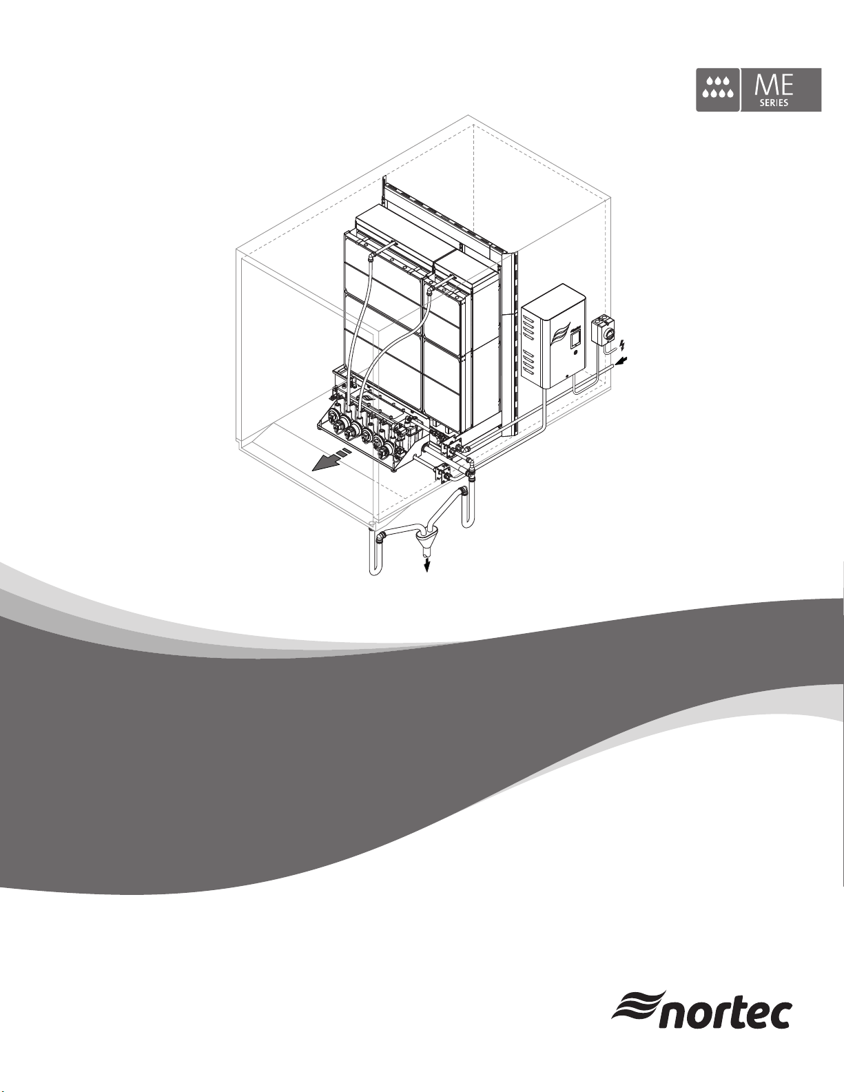
Adiabatic air humidification/air cooling system
Nortec ME Control
Humidication and Evaporative Cooling
Page 2

Thank you for choosing Nortec
Installation date (MM/DD/YYYY):
Commissioning date (MM/DD/YYYY):
Location ref.:
Model:
Serial number:
Manufacturer
Condair Plc
Artex Avenue, Rustington,
Littlehampton, West Sussex.
BN16 3LN (UK)
TEL: +44(0)1903 850 200
FAX: +44(0)1903 850 345
www.Nortec.co.uk
Proprietary Notice
This document and the information disclosed herein are proprietary data of Condair Plc. Neither this document, nor
the information contained herein shall be reproduced, used, or disclosed to others without the written authorization
of Condair Plc, except to the extent required for installation or maintenance of recipient's equipment.
Liability Notice
Condair Plc does not accept any liability due to incorrect installation or operation of the equipment or due to the
use of parts/components/equipment that are not authorized by Condair Plc.
Copyright Notice
Copyright 2014, Condair Plc All rights reserved.
Technical modications reserved
Page 3

Contents
1 Introduction 5
1.1 General 5
1.2 Notes on the operation manual 5
2 For your safety 7
3 Product Overview 10
3.1 Model overview 10
3.2 Product designation / Which model do you have 11
3.3 Construction of the system components 12
3.3.1 Construction of the evaporative module 12
3.3.2 Construction of the hydraulic module 13
3.4 System overviews / Functional description 14
3.4.1 Typical system Nortec ME Control (internally mounted) 14
3.4.2 Typical system Nortec ME Control (externally mounted) 15
4 Operation 18
4.1 Important notes on operation 18
4.2 Initial commissioning 19
4.3 Display and operating elements 21
4.4 Start up for daily operation 22
4.5 Notes on operation 23
4.5.1 Important notes on operation 23
4.5.2 Remote operating and fault indication 23
4.5.3 Recommended regular checks during operation 23
4.5.4 Manual draining of the water tank 24
4.5.5 Performing a matrix wash over 25
4.6 Decommissioning the system 26
5 Operating the Nortec ME control software 27
5.1 Standard operating display 27
5.1.1 Operating status indication 28
5.1.2 Maintenance and malfunction indications 29
5.2 Navigating/operating the Nortec ME control software 30
5.3 Information functions 31
5.3.1 Accessing support information 31
5.3.2 Accessing system information 31
5.4 Conguration 34
5.4.1 Accessing the “Conguration” submenu 34
5.4.2 Conguring dilution and drain cycle functions – “Features” submenu 34
5.4.3 Control settings – “Control Settings” submenu 36
5.4.4 Basic settings – “General” submenu 38
5.4.5 Communication settings – “Communication” submenu 39
3Contents
Page 4

5.5 Service functions 40
5.5.1 Accessing the “Service” submenu 40
5.5.2 Performing maintenance functions – “Service” submenu 40
5.5.2.1 Input diagnostic functions – “Input Diagnostics” submenu 44
5.5.2.2 Output diagnostic functions – “Output Diagnostics” submenu 47
5.5.2.3 Relay diagnostic functions – “Relay Diagnostics” submenu 48
5.6 Administration settings 49
5.6.1 Accessing “Administrator” submenu 49
5.6.2 Administration settings – “Administrator” submenu 49
6 Maintenance 51
6.1 Important notes on maintenance 51
6.2 Maintenance intervals 52
6.3 Maintenance guide 52
6.4 Dismantling and installation of components for maintenance 54
6.4.1 Dismantling and installation of the evaporative module 54
6.5 Consumables guide 55
6.6 Health and safety requirements 55
6.7 Routine water sampling and testing 56
6.8 Cleaning and disinfection 57
6.9 Cleaning and disinfection method statement 58
6.10 Resetting the maintenance indication on Nortec ME Control 60
6.11 Performing software updates 61
7 Fault elimination 62
7.1 Fault indication on Nortec ME Control control unit 62
7.2 Malfunction list 63
7.3 Saving fault and service histories to a USB memory stick 68
7.4 Malfunctions without indication 68
7.5 Notes on fault elimination 69
7.6 Replacing the fuses and backup battery in the control unit 70
7.7 Resetting the fault status on Nortec ME Control 71
8 Taking out of service/Disposal 72
8.1 Taking out of service 72
8.2 Disposal/Recycling 72
9 Productspecications 73
9.1 Technical data 73
10 Appendix 74
10.1 Wiring diagram Nortec ME Control 74
4 Contents
Page 5

1 Introduction
1.1 General
We thank you for having purchased the NortecMEControlEvaporativeHumidierandCooler(Nortec
ME Control for short).
The Nortec ME Control incorporates the latest technical ad van ces and meets all recognized safety
standards. Nevertheless, improper use of the Nortec ME Control may result in danger to the user or
third parties and/or impairment of material assets.
To ensure a safe, proper, and economical operation of the Nortec ME Control, please observe and
comply with all information and safety instructions contained in the present documentation as well as in
the separate documentations of the components installed in the humidication system.
If you have questions after reading this documentation, please contact your Nortec representative. They
will be glad to assist you.
1.2 Notes on the operation manual
Limitation
ThesubjectofthisoperationmanualistheNortecMEControlEvaporativeHumidierandCooler.
The various options and accessories are only described insofar as is necessary for proper operation of the
equipment. Further information on options and accessories can be obtained in the respective instructions.
This operation manual is restricted to the operation, the maintenance and troubleshooting of the
Nortec ME Control and is meant for well trained personnelbeing sufciently qualiedfor their
respective work.
Please note, some illustrations in this manual may show options and accessories which may not be
supplied as standard or available in your country. Please check availability and specication details with
your Nortec representative.
The operation manual is supplemented by various separate items of documentation (such as the installation manual), which are included in the delivery as well. Where necessary, appropriate cross-references
are made to these publications in the operation manual.
5Introduction
Page 6
Symbols used in this manual
CAUTION!
The catchword “CAUTION” used in conjunction with the caution symbol in the circle designates notes
in this operation manual that, if neglected, may cause damage and/or malfunction of the unit or
other material assets.
WARNING!
The catchword “WARNING” used in conjunction with the general caution symbol designates safety
and danger notes in this operation manual that, if neglected, may cause injury to persons.
DANGER!
The catchword “DANGER” used in conjunction with the general caution symbol designates safety and
danger notes in this operation manual that, if neglected, may lead to severe injury or even death
of persons.
Safekeeping
Please safeguard this operation manual in a safe place, where it can be immediately accessed. If the
equipment changes hands, the operation manual must be passed on to the new operator.
If the operation manual gets mislaid, please contact your Nortec representative.
Language versions
This operation manual is available in various languages. Please contact your Nortec representative for
information.
6 Introduction
Page 7

2 For your safety
General
Every person working with the Nortec ME Control must have read and understood the operation manual
of the Nortec ME Control before carrying out any work.
Knowing and understanding the contents of the operation manual is a basic requirement for protecting
the personnel against any kind of danger, to prevent faulty operation, and to operate the unit safely and
correctly.
All ideograms, signs and markings applied to the components of the Nortec ME Control must be observed
and kept in readable state.
Qualicationofpersonnel
All work described in this operation manual may only be carried out by specialists who are well
trainedandadequatelyqualiedandareauthorizedbythecustomer.
For safety and warranty reasons any action beyond the scope of this manual must be carried out only
by qualied personnel authorised by the manufacturer.
It is assumed that all persons working with the Nortec ME Control are familiar and comply with the appropriate local regulations on work safety and the prevention of accidents.
The Nortec ME Control may not be used by persons (including children) with reduced physical, sensory
or mental abilities or persons with lacking experience and/or knowledge, unless they are supervised by
a person responsible for their safety or they received instructions on how to operate the system.
Children must be supervised to make sure that they do not play with the Nortec ME Control.
Intended use
The Nortec ME Control is intended exclusively for
ducts within the specied operating conditions. Any other type of application, without the written consent
of the manufacturer, is considered as not conforming with the intended purpose and may lead to the
Nortec ME Control becoming dangerous.
Operation of the equipment in the intended manner requires that all the information contained in this
operation manual are observed (in particular the safety instructions).
airhumidicationandaircoolinginAHU'sorair
7For your safety
Page 8
Danger that may arise from the Nortec ME Control
DANGER!
Risk of electric shock!
The Nortec ME control unit (and the optional submerged UV system) contain live mains voltage.
Live parts may be exposed when the control unit (or the terminal box of the optional submerged
UV system) is open. Touching live parts may cause severe injury or danger to life.
Prevention: Before carrying out any work on the Nortec ME Control switch off the control unit, dis-
connect it from the mains via the electrical isolator and secure the electrical isolator in “Off” position
against inadvertent power-up.
DANGER!
Healthriskbecauseofinadequatehygiene!
Inadequately operated and/or poorly maintained evaporative humidication/cooling systems may endanger health. When inadequately operated and/or poorly maintained micro-organisms (including the
bacterium which causes Legionnaire’s disease) may grow in the evaporative module, the water tank
and the water system of the Nortec ME Control and may affect the air in the AHU/air duct.
Prevention: the Nortec ME Control must strictly be operated and maintained in accordance with this
manual.
WARNING!
Some type of evaporative material is manufactured from glass bre. Though this material is not classi-
ed as hazardous, it is recommended that Personal Protection Equipment such as gloves, protective
clothing and eye protection are used during handling to protect the user from bres or dust. If dust is
generated during handling it is recommended that respiratory protection is worn.
Correct lifting and handling
Lifting or handling of components must only be carried out by trained and qualied personnel. Ensure
that the lifting operation has been properly planned and risk assessed, and that all equipment has been
checked by a skilled and competent Health & Safety representative.
It is the customer's responsibility to ensure that operators are trained in handling heavy goods and to
enforce the relevant lifting regulations.
8 For your safety
Page 9

Preventing unsafe operation
If it is suspected that safe operation is no longer possible, then the Nortec ME Control should immediately be shut down and secured against accidental power-up according to chapter 4.6 – Decom-
missioning the system. This can be the case under the following circumstances:
– if the Nortec ME Control is damaged
– if the Nortec ME Control is contaminated
– if the electrical installations are damaged
– if the Nortec ME Control is no longer operating correctly
– if connections and/or piping are leaking
All persons working with the Nortec ME Control must report any alterations to the system that may affect
safety to the owner without delay.
Prohibitedmodicationstotheunit
Nomodicationsmustbeundertaken on the Nortec ME Control without the express written consent
of the manufacturer.
For the replacement of defective components use exclusively original accessories and spare parts
available from your Nortec representative.
9For your safety
Page 10

3 Product Overview
3.1 Model overview
As standard the Nortec ME Control consist of:
– Evaporative module (75%, 85 % or 95 % efciency depending on the cassette type)
– Hydraulic module (mounted internal or external to the duct)
– Control unit with integrated controller with touch panel
According to your order the Nortec ME Control can be equipped with the following options:
– Droplet separator
– Evaporative module blanking
– Hydraulic module cover
– Remote operation and fault indication
– BMS connectivity
– Freeze protection stat
– Leak detection
– Conductivity monitoring
– Submerged UV or In-Line UV
– PureFlo Ag+
– Dosing pump
– Electrical isolator
10 Product Overview
Page 11
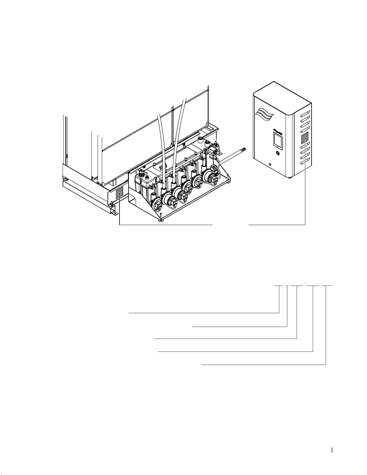
3.2 Product designation / Which model do you have
The product designation and the most important unit data (e.g. serial number, evaporative module
product, etc.) are found on the rating plate xed on the left side of the evaporative module and on the
right side of the control unit.
Fig. 1: Position of rating plate
Evaporative module product key
Product idencation
ME (media evaporator)
Product version (consecutive version number):
Width evaporative module in mm
Height evaporative module in mm
Material type and efciency evaporative cassettes:
F75= Glass bre 75 %
F85= Glass bre 85 %
F95= Glass bre 95 %
P85= Polyester 85 %
P95= Polyester 95 %
Rating Plate
Example:
ME-1-0900-1125-F95
11Product Overview
Page 12
3.3 Construction of the system components
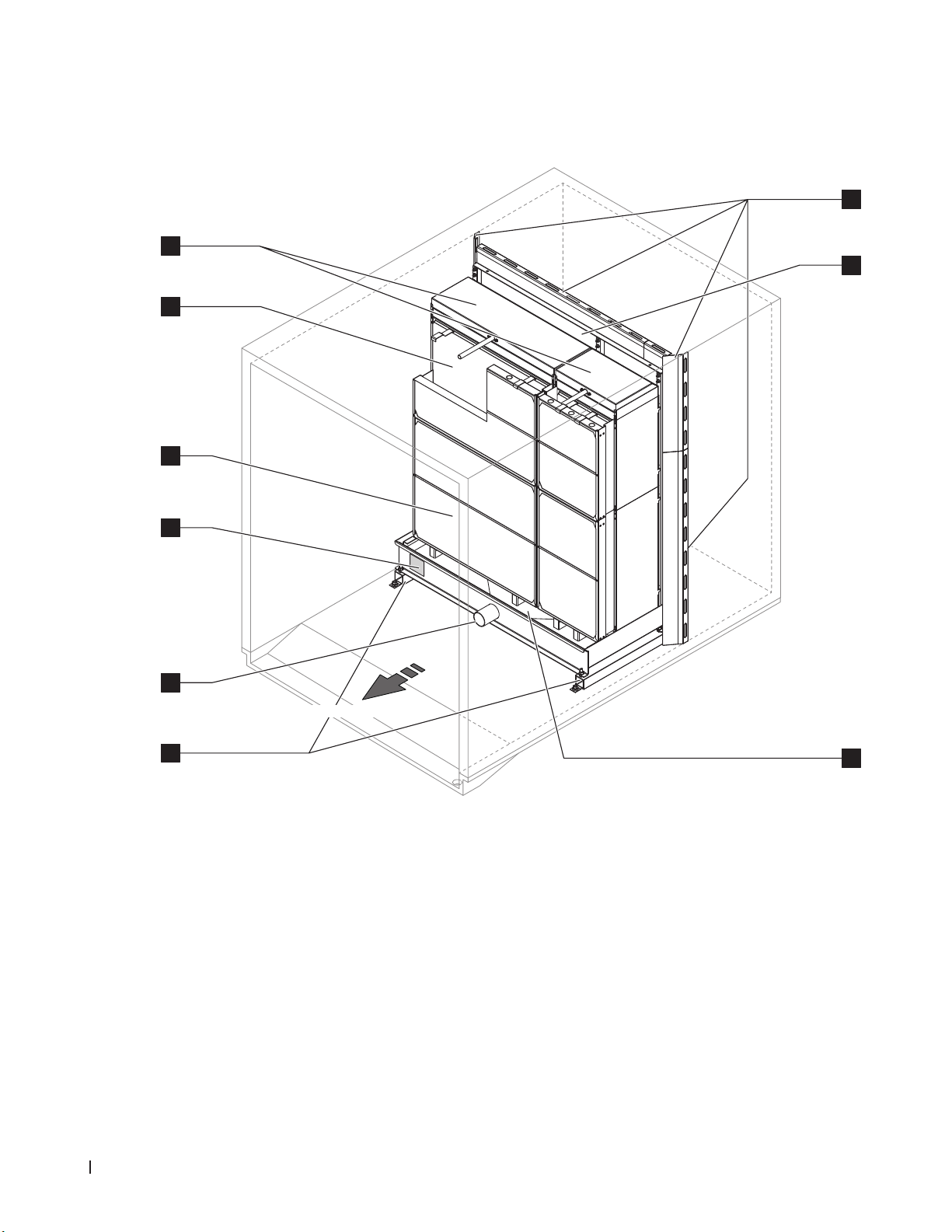
3.3.1 Construction of the evaporative module
6
5
4
3
7
8
2
air ow direction
1
1 Upstands
2 Tank connector ø54 mm (2.125")
3 Rating plate
4 Droplet separator, mandatory for face velocity
>3.5 m/s (>689 fpm)
Fig. 2: Construction of the evaporative module
9
5 Evaporative cassettes (F75, F85, F95, P85 or P95)
6 Distribution heads
7 Blanking plates (option)
8 Mounting frame for evaporative cassettes
9 Water tank
12 Product Overview
Page 13
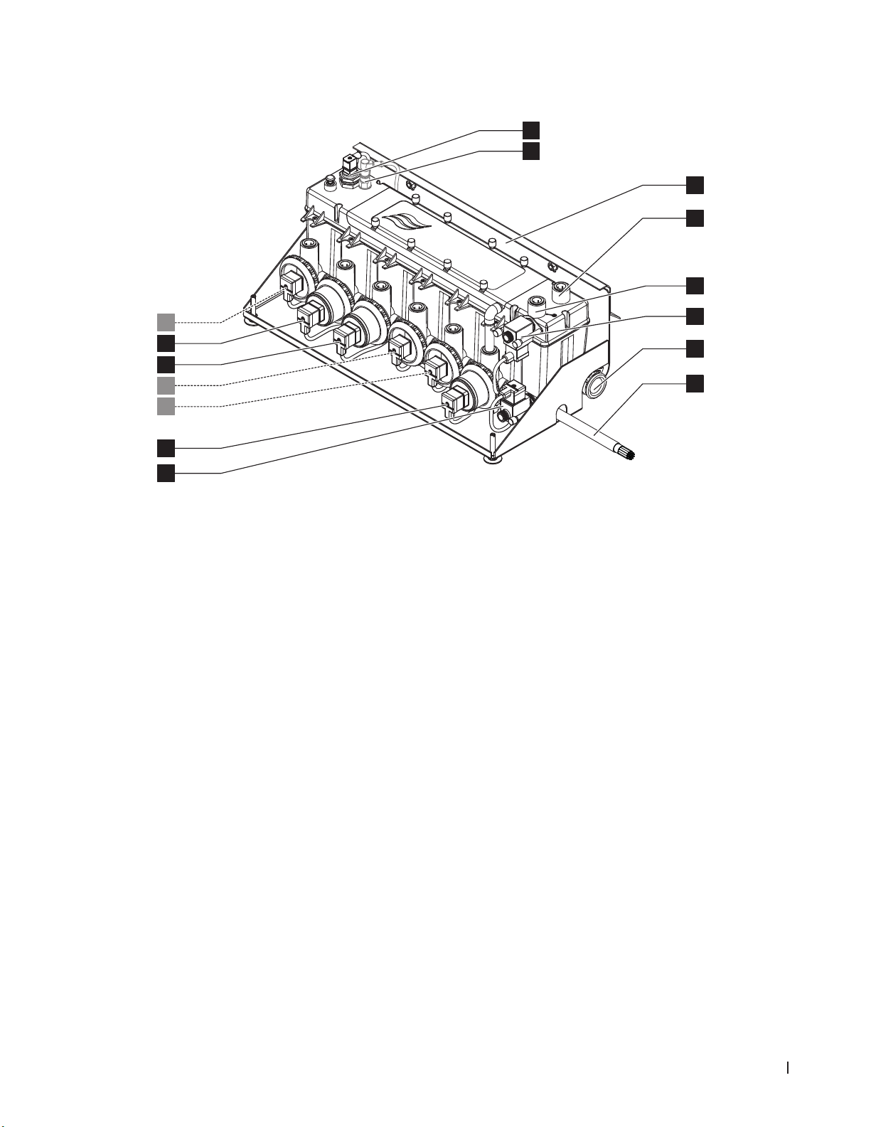
3.3.2 Construction of the hydraulic module
8
9
10
11
12
7
6
5
4
3
2
1
1 Drain valve (normally open)
2 Drain pump
3 Stage pump 5 with push-t connector ø15 mm (0.625")
4 Stage pump 3 with push-t connector ø15 mm (0.625")
5 Stage pump 1 with push-t connector ø15 mm (0.625")
6 Stage pump 2 with push-t connector ø15 mm (0.625")
7 Stage pump 4 with push-t connector ø15 mm (0.625")
8 Level sensor
9 Conductivity sensor (option)
10 Fixing bracket
11 Push-t connector ø15 mm (0.625") pressure equali-
sation (only used when mounted outside of AHU)
12 Water supply push-t connector ø15 mm (0.625")
13 Inlet valve (normally closed)
14 Drain connector ø28 mm (1.125")
Note: drain connector can be turned 180° to drain
through the left or the right duct wall
15 Interconnecting cable hydraulic module
Fig. 3: Construction of the hydraulic module (gure shows layout for 2-stage control)
13
14
15
13Product Overview
Page 14
3.4 System overviews / Functional description
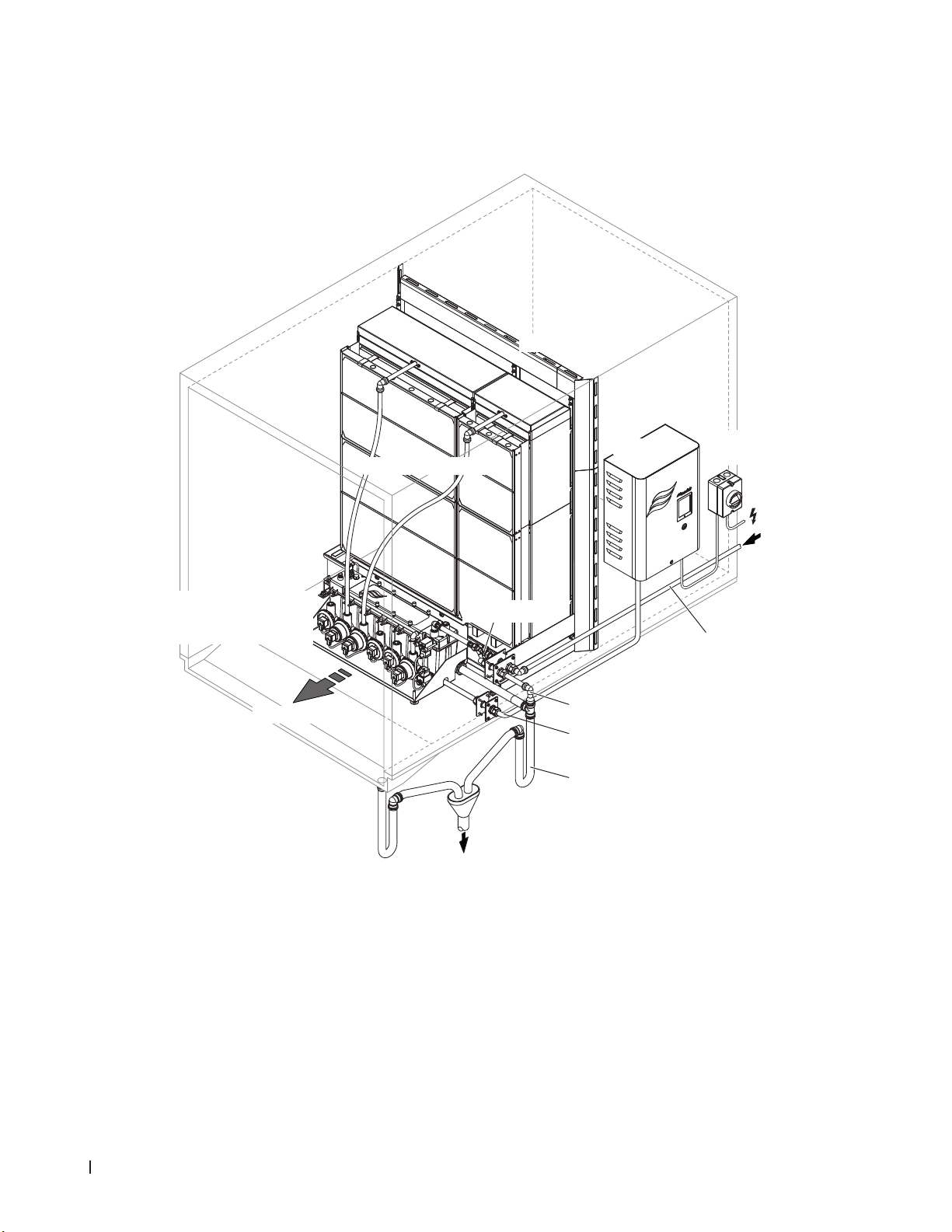
3.4.1 Typical system Nortec ME Control (internally mounted)
Blanking plates
Evaporative module
Hydraulic module (with
supply valve, drain valve
and stage pumps)
Air ow direction
AHU drain
with trap
Shut-off valve
Fig. 4: Typical system Nortec ME Control (internally mounted)
Control unit
Vent drain pipe
Inter connecting cable
hydraulic module
Tank drain with trap
Electrical
isolator
Water supply line
14 Product Overview
Page 15
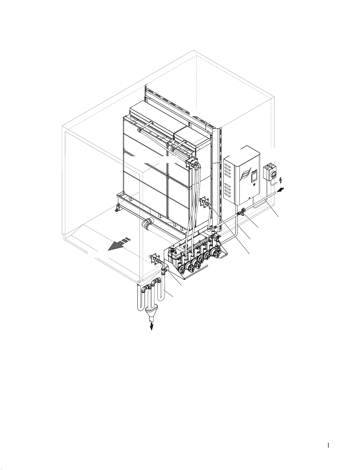
3.4.2 Typical system Nortec ME Control (externally mounted)
Blanking plates
Air ow direction
AHU drain
with trap
Evaporative module
Hydraulic module (with
supply valve, drain valve
and stage pumps)
Vent drain pipe
Tank drain with trap
Control unit
Electrical
isolator
Water supply line
Shut-off valve
Inter connecting cable
hydraulic module
Pressure equalisation
Fig. 5: Typical system Nortec ME Control (externally mounted)
15Product Overview
Page 16
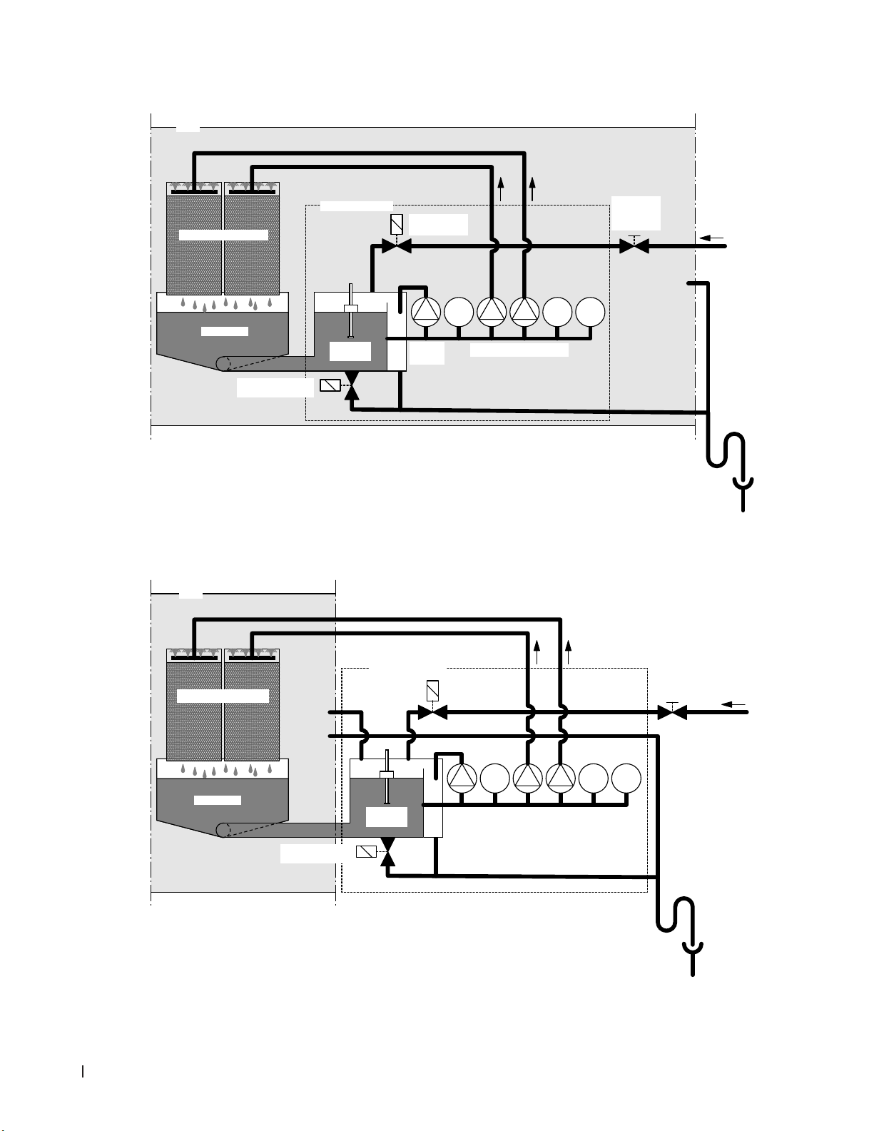
Schematicowdiagram
AHU
Hydraulic module
Evaporative cassettes
Inlet solenoid
valve (NC)
2 1 34
Water tank
Gravity solenoid
drain valve (NO)
Level
sensor
Drain
pump
Stage pumps 2... max. 5)
Fig. 6: Schematic ow diagram Nortec ME Control (internally mounted)
AHU
Shut-off
valve with
strainer
Drain vent
to duct
5
Drain trap
(building side)
Tundish
(building side)
Evaporative cassettes
Fig. 7: Schematic ow diagram Nortec ME Control (externally mounted)
16 Product Overview
Water tank
Gravity solenoid
drain valve (NO)
Hydraulic module
Pressure
equalisation
Level
sensor
Inlet solenoid
valve (NC)
Drain
pump
2 1 34
Stage pumps 2... max. 5)
5
Drain trap
(building side)
(building side)
Shut-off
valve with
strainer
Drain vent
to duct
Tundish
Page 17

Functional description
The water tank is lled up to a preset upper level via the level-controlled inlet solenoid valve (NC). When
the water level in the water tank drops below a certain limit, the level-controlled inlet solenoid valve opens
until the upper limit is reached again.
The Nortec ME Control provides On/Off or stage control by means of the Nortec ME Control control unit
and the stage pumps. The Nortec ME Control control unit processes analog sensor/control signals and
uses them to control the stage pumps.
In case of a humidication/cooling request with activated On/Off control the inlet solenoid valve (NC)
opens and all stage pumps start and the water ows to the distribution header above the evaporative
cassettes.
In case of a humidication/cooling request with activated stage control the inlet solenoid valve (NC)
opens, then one, two, three, four or all ve stage pumps start (depending on the demand signal and
evaporative module size) and the water ows to the distribution header above the evaporative cassettes.
The distribution pipes inside the distribution header evenly supply the water to the entire surface of the
evaporative cassettes where it ows down and humidies the air owing through the evaporative cassettes. The excess water not used for humidication ows to the water tank.
To prevent accumulation of mineral residues and the formation of germs in the water tank, the tank is
completely drained periodically (interval or time controlled). Additionally further hygiene functions can
be activated: Operation-dependent draining of the water tank (ll cycle, conductivity, temperature or
time controlled).
17Product Overview
Page 18
4 Operation
4.1 Important notes on operation
Qualicationofpersonnel
The Nortec ME Control must be commissioned and op erated only by personnel familiar with the system
and adequately qualied for the respective tasks. It is the owner’s responsibility to verify proper qualication of the operating personnel.
General notes
The instructions and details regarding commissioning and operation must be followed and upheld.
The initial commissioning of the Nortec ME Control requires appropriately trained technical personnel.
It is strongly recommended that your Nortec representative commissions your system. Part of this initial
commissioning process is a disinfection of the water tank, and if required the evaporative cassettes.
Please read this document in full before commencing any work.
Please pay attention to local regulations regarding working at heights and electrical work.
Safety and hygiene
DANGER!
The Nortec ME Control must be operated in accordance with this manual. Failure to do so could
result in contamination that might cause Legionnaires’ disease, which can be fatal.
WARNING!
The Nortec ME control unit should not be electrically isolated for periods exceeding 24 hours
as automatic drain and purge cycles will be disabled.
18 Operation
Page 19

4.2 Initial commissioning
The initial commissioning of the Nortec ME Control requires appropriately trained technical personnel.
We strongly recommend that your Nortec representative commissions your system.
Inspections
Prior to initial commissioning the complete system must be inspected for correct execution of the installations. Proceed as follows:
1. Switch off AHU.
2. Evaporative module installation: Check correct selection of evaporative module on rating plate if
multiple units on site. Check that the evaporative module has been installed level in all planes with
secure blanking plates to prevent air bypass. Check that there is sufcient access for cassette removal during maintenance. Ensure assembly is securely xed, and that there is no visible damage.
Check that the evaporative module is installed in a waterproof section. Check evaporative module
(including tank) is free of dirt/ debris and clean as necessary.
3. Control unit installation: Check that the control unit is mounted in a convenient dry location
4. Supply water Installation: Ensure the water system in the building has been subject to a Risk Assessment. The Nortec ME Control must be connected to a clean, wholesome mains water sup-
ply. It is the responsibility of the user to ensure that the water system complies with local regulations
and bylaws, particularly those for the control of Legionella microbes. The use of mains water fed
tanks and reservoirs is only permitted as part of a managed water treatment system. Check that the
evaporative module has a feed water supply in excess of 2 bar (29 psi) connected to the supplied
approved lling hose. Ensure that any hygiene options have been correctly installed. Check all joints
and ttings for leaks.
5. Drain installation: Check that the drain line is made according to the corresponding instructions
given in the installation manual. Ensure the drain line is connected to the main building drain and
that drain pipework is trapped to a suitable level for the applicable working duct pressure. Check all
joints and ttings. Ensure that the drain connection includes an air gap.
6. Distribution pipework: Check all water distribution pipework between the hydraulic module and
the distribution headers are securely tted.
7. Electrical wiring: Check all electrical connections with reference to the corresponding wiring diagram
in this manual. Check that a 100...240V / 10A single phase supply is connected to the control unit.
Ensure that this power supply is isolated with an electrical isolator within 1 m (39") of the control unit.
8. Optional controls: Check that appropriate controls connections have been made to the control unit.
Refer to the controls wiring section of the installation manual.
9. Flushwatersupplyandtestsupplywaterquality: Disconnect water supply pipe from connector
on the hydraulic module. Fix hose to free end of supply pipe and lead hose to a drain. Carefully ush
supply pipe a suitable amount of time without creating splashing or aerosols.
Take a water quality sample to ensure that supply water meets the requirements specied in the
water quality guide. The sample should be tested using a dip slide to indicate the total number of
colony forming units per ml (cfu/ml). Generally, levels of 1x10
3
cfu/ml may be considered acceptable
for this type of humidier provided the species of microbes and/or fungi involved are themselves not
considered to be harmful. If you are unsure of the quality of your water please consult your Nortec
distributor for advice.
Then reconnect the water supply pipe to the supply connector on the hydraulic module.
19Operation
Page 20

10. Perform pressure test: Turn on water supply and check for leaks. Ensure double check valve is
installed correctly.
After the system has been inspected and found correct proceed with the initial commissioning:
1. Ensure AHU is switched off.
2. Switch on electrical isolator, and then the <Humdication/CoolingOn/Off> and the <Control unit
On/Off> switch on the control unit.
3. Enter the activation code (see chapter 5.5.2 – Performing maintenance functions – “Service” sub-
menu).
4. Perform a matrix wash over cycle (see chapter 5.5.2 – Performing maintenance functions – “Service”
submenu).
5. Check correct water level and pump activation.
6. Check water can ow to drain correctly.
7. Allow system to ush until water is clean.
8. Simulate full demand and check components are operating correctly.
9. Test correct ow of water to distribution header.
10. Test any tted options (see relevant option addendum manual).
11. If evaporative cassettes have become dirty or damp, follow the disinfection procedure described in
sections 6.3 and 6.9 of this manual.
12. Switch on fan of AHU and test operation with fans running and validate air conditions against the
design data.
13. From full saturation – time drain cycle (with fan in design condition).
14. Test control devices.
15. Correctly congure Nortec ME control unit (setpoints, control settings, etc.) according to the situation
on site (see chapter 5.4 – Conguration).
16. Drain tank, wipe tank clean, re-ll tank and add DISIFIN XL chemical according to tank volume.
17. If commissioning has not been completed by an approved Nortec representative, it is recommended
that records are kept of commissioning date and software settings.
18. Demonstrate system to customer and highlight hygiene and maintenance requirements.
19. Raise any installation concerns.
20. Issue commissioning documentation.
The system is now ready for normal operation.
20 Operation
Page 21
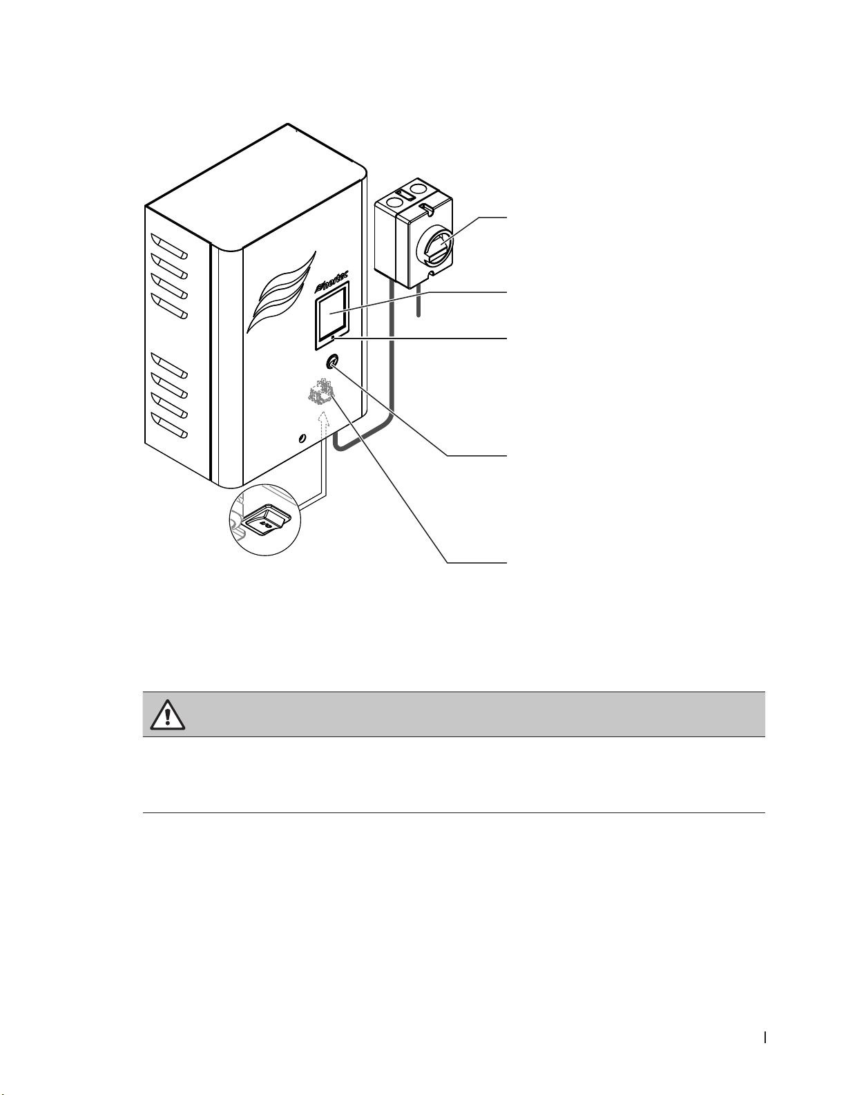
4.3 Display and operating elements
Humidier
1 Electrical isolator
Note: the electrical isolator (supplied by the customer) must be installed in the mains supply line!
2 Touch screen
3 Status LED
– green: Nortec ME Control is
humidifying/cooling
– green pulsing: No demand or humidica-
tion/cooling is switched off
– orange: Warning present or maintenance
due
– red: Fault present
4 <Humdication/CoolingOn/Off>switch
Note: with this switch the humidication/cooling
function can be activated and deactivated. The
hygiene functions (regular ushing of the water
system) remain still active even with deactivated
humidication/cooling function.
5 <ControlunitOn/Off>switch (located on
the bottom of the control unit)
Note: with this switch you can switch on and off
the control unit. If the control unit is switched off
all functions (including hygiene functions) of the
Nortec ME Control are deactivated.
Fig. 8: Display and operating elements Nortec ME
DANGER!
Risk of electric shock!
Since mains supply to the control unit is not interrupted by switching off the
<Humdication/Cooling
On/Off> switch and there is still mains voltage inside the control unit even when you switch off the
<ControlunitOn/Off> switch too, the electrical isolator must be switched off before open the
control unit.
21Operation
Page 22
4.4 Start up for daily operation
It is assumed that initial commissioning has been carried out properly by the service technician of your
Nortec representative.
If the Nortec ME Control has been out of operation for a prolonged period of time, a complete
system service has to be performed prior to the start up.
The following description outlines the start up procedure for daily operation. Proceed as follows to prepare the Nortec ME Control for operation:
1. Switch off AHU.
2. Examine the Nortec ME Control for possible damage and faulty installation. Ensure tank is empty.
DANGER!
Damaged systems or systems with damaged components or faulty installations may present danger
to human life or cause severe damage to material assets.
Damaged systems and/or systems with damaged or faulty installation must not be operated.
3. Close doors of AHU if open, then switch on AHU if switched off.
4. Open shut-off valve in the water supply line.
5. Make sure the front panel of the control unit is mounted and xed with the retaining screw.
6. Switch on the electrical isolator in the mains supply line (mains supply to control unit).
7. Switch <ControlunitOn/Off> and <Humdication/CoolingOn/Off>switch on the control unit to
“On”, and activate control unit via the external enable switch if necessary. Check for any fault or
service message.
8. If Nortec ME Control has been disconnected from the mains for more than 48 hours the message
“Out of Commissioning” appears. If this is the case proceed as follows:
• Switch off control unit via the <ControlunitOn/Off> switch.
• Risk assess the system and check the need for disinfection.
• Close shut-off valve in the water supply line.
• Disconnect water supply line from the connector on the hydraulic module. Caution should be
taken to ensure no splashing is created.
• Connect hose to the open end of the water supply line and lead the hose into open tundish
outside the AHU.
• Open shut-off valve in the water supply line and ush water supply line an appropriate length of
time. Then, close shut-off valve again, remove hose and reconnect supply line to the connector
on the hydraulic module.
• Switch on control unit via the <ControlunitOn/Off> switch.
Note: After switching on the control unit the “Out of Commissioning” message appears again, however the message is reset automatically after 1 minute and the Nortec ME Control continues with
normal operation.
22 Operation
The Nortec ME Control is now in normal operating mode and the standard operating display is shown.
Note: further information on the operation of the Nortec ME control software can be found in chapter 5
– Operating the Nortec ME control software.
Page 23
4.5 Notes on operation
4.5.1 Important notes on operation
– For hygiene reasons the supply valve opens in standby mode every 12 hours for approximately
20 seconds in order to ush water supply line.
– If no demand is present for more than 23 hours the tank will be drained.
4.5.2 Remote operating and fault indication
The relays on the remote operating and fault indication board indicate the following operating system
status:
Activated
remote indication relay
“Error” An error is present, operation is stopped or further operation is possible for a limited period
“Service” One of the maintenance counter has elapsed. The corresponding maintenance must be
“Running” Demand present/system is humidifying/cooling
“Unit on” The humidication system is switched on and under voltage
When?
of time only.
performed.
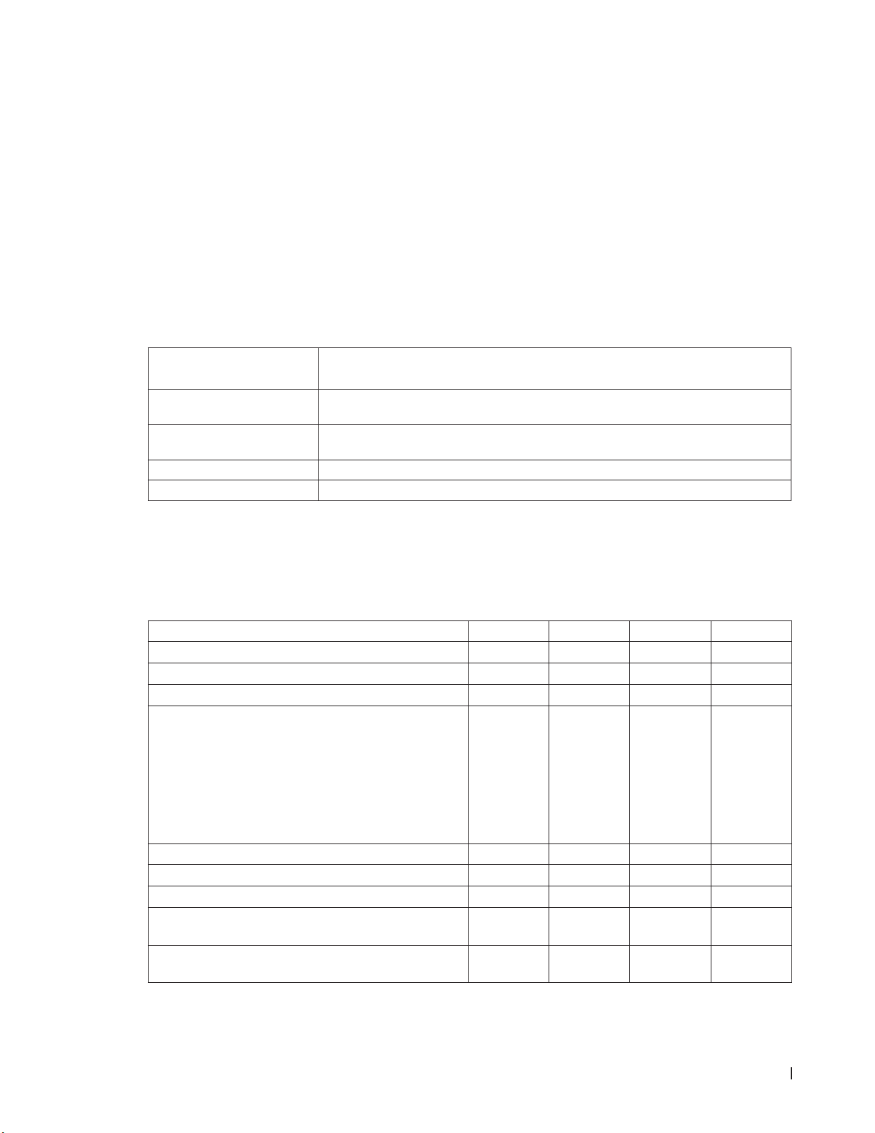
4.5.3 Recommended regular checks during operation
During operation the Nortec ME Control has to be checked periodically in accordance with the table below.
Operations Checks Daily Weekly Monthly Quarterly
Monitor humidity/temperature control
Check for any low humidity/temperature concerns
Check any alarms on BMS
Visible check for:
Units switched on with no fault lights
–
– No water leakage (air on and air off side)
– No water ow to drain (water may ow to drain during
drain cycle and when unit losses humidity demand)
– system components for correct xing and any da-
mage
– electric installation for any damage.
All UV bulbs are active (with water level), if applicable
Matrix media is saturated (relative to demand signal)
Condition of tanks and air on matrix is clean
Inspect and determine replacement frequency of sediment lter
Add DisinXL chemical (
of tank)
1 sachet per 2 m (6.6 ft) width
23Operation
Page 24

Operations Checks Daily Weekly Monthly Quarterly
Conductivity (reading below set point)
Correct software settings
Condition of tanks are clean (clean as required)
Water level is correct (ensure unit Is not in drain cycle)
If the checks reveal any irregularities (e.g. leakage, error indication) or any damaged components take
the Nortec ME Control out of operation as described in chapter 4.6 – Decommissioning the system.
Then, have the malfunction eliminated or the damaged component replaced by a well trained specialist
or a service technician from your Nortec representative.
4.5.4 Manual draining of the water tank
If a manual draining of the water tank is required proceed as follows:
1. Close shut-off valve in the water supply line.
2. Press on the <Drain> button in the standard operating display.
3. Press on the menu item <Drain>. The drain conrmation dialogue appears.
4. Press on the <Yes> button to start draining of the water system. A possible running humidication/
cooling process is interrupted. The progress bar in the display shows the current status of the drain
process. After the tank is drained the control unit returns to the “Manual” submenu.
Note: in order to stop the drain process press the <Cancel> button in the progress window. The
drain process is stopped and the control unit returns to the “Manual” submenu.
24 Operation
Page 25

4.5.5 Performing a matrix wash over
At initial commissioning when the “Matrix Wash Over” (W49) message appears or any time new evaporative cassettes have been installed, a matrix wash over cycle has to be performed. If a matrix wash over
cycle is required proceed as follows:
Password: 8808
Nortec ME Control is in normal operation mode.
1. Select the “Service” submenu (displays 1-3)
2. Select “Matrix Wash Over” function in the “Service” submenu. The matrix wash over conrmation
dialogue appears.
3. Press on the <Yes> button to start the matrix wash over. A possible running humidication/cooling
process is interrupted. The progress bar in the display shows the current status of the matrix wash
over process. After the matrix wash over process is nished the control unit returns to the “Service”
submenu.
Note: in order to stop the matrix wash over process press the <Cancel> button in the progress win-
dow. The matrix wash over process is stopped and the control unit returns to the “Service” submenu.
25Operation
Page 26

4.6 Decommissioning the system
In order to decommission the Nortec ME Control (e.g. to perform maintenance works, to eliminate a
malfunction, etc.) perform the following steps:
1. If the system has to be switched off because of a malfunction, please note the Warning and Fault
code(s) of the actual error message(s) shown in the fault history.
2. Close the shut-off valve in the water supply line.
3. Empty the water tank with the manual drain function (see chapter 4.5.4 – Manual draining of the
water tank).
4. Switch off <Humdication/CoolingOn/Off> and <ControlunitOn/Off> switch on the control unit,
and if necessary deactivate control unit via the external enable switch.
5. Disconnect control unit from the mains: switch off the electrical isolator in the mains supply to
the control unit and secure switch in “Off” position against accidentally being switched on, or clearly
mark the switch.
6. Let the fan of the ventilation system run until the evaporative module is dry.
7. If work has to be carried out on the evaporative module or the hydraulic module mounted inside the
duct, switch off the AHU and secure the system against accidentally being switched on.
Important Notes!
– For reasons of hygiene, we recommend that the control unit should be left powered on even if the
Nortec ME Control is not being used for a longer period of time. Only the <Humdication/Cooling
On/Off> switch should be switched off. This keeps the hygiene functions (e.g. periodical ushing of
water supply pipe) active and hence the build-up of germs is opposed.
– If the Nortec ME system is isolated from the mains for prolonged periods, water stagnation
might occur in supply pipework and microbial contamination result, therefore the system,
including any storage tanks or vessels should be drained and left dry. Before putting the system
back into operation, a full risk assessment should be undertaken to ensure safe operation, with
particular attention paid to water supply quality. Additionally a complete system service has to
be performed prior to putting the system back in operation.
26 Operation
Page 27

5 Operating the Nortec ME control software
5.1 Standard operating display
After switching on the control unit and the automatic system test the control unit is in normal operating
mode and the standard operating display is shown.
Note: the appearance of the standard operating display depends on the current operating status and
the conguration of the humidity/temperature regulation of the system and can deviate from the display
shown below.
The standard operating display is structured as follows:
Current operating status
(see chapter 5.1.1 – Operating status indication)
Humidity/temperature regulation information
Maintenance/malfunctions indication eld
(see chapter 5.1.2 – Maintenance and malfunction indications)
Access Help screen
Drain tank
Access system information
Access main menu
Fig. 9: Standard operating display
27Operating the Nortec ME control software
Page 28

5.1.1 Operating status indication
The following operation status indications may appear during operation:
Operating status indication Description
The control is initialising.
No humidity demand for more than 60 minutes the humidication system is in standby mode. The
water system is ushed automatically for 300 seconds before the next humidication takes place.
The Nortec ME is humidifying.
The Nortec ME is cooling.
The Nortec ME holds the current water level in the tank to be ready for operation.
The Nortec ME is draining the tank.
If the water conductivity is not decreasing after a dilution, a water refresh cycle will be carried
out (rell of the full tank). Note: This message appears only, if the system is equipped with the
conductivity monitoring option.
The Nortec ME is lling the tank.
The water in the tank is being diluted to minimise limescale.
After the demand has dropped to zero, the system drains a small amount of water to give space
to the rest water held in the matrix.
During operation the stage pumps are stopped periodically to bleed any air out of the pumps
by the water owing back from the distribution pipes.
The Nortec ME is ramping up the water duty to the matrix.
The operation is manually switched off.
The Nortec ME was stopped via the external enable switch.
The inlet pipework is being purged.
The ME is in diagnostic mode, e.g. wash over activation through BMS.
The humidication system is stopped due to a malfunction which obviates further operation.
Additionally “Warning” or “Fault” is displayed in the maintenance and malfunction eld.
28 Operating the Nortec ME control software
Page 29

5.1.2 Maintenance and malfunction indications
The following maintenance and malfunction indications may appear during operation:
Operating status indication Description
No malfunction present. By pressing on the indication eld the service menu can be accessed.
The system service is due. If the system service is not performed within 30 days a fault message is triggered. The system remains operable.
The external liquid container of the dosing pump is empty.
The lifetime of the PureFlow Ag+ cartridge has expired and must be replaced.
The lifetime of the UV bulb has expired and must be replaced.
As new matrix has been installed, a matrix wash over cycle needs to be carried out.
This message appears after switching on, if the control unit has been isolated from the mains
supply for more than 48 hours. The humidication system is blocked for 5 minutes. Before operation the RO water supply line to the central unit must be ushed. The commissioning warning
is reset automatically after 5 minutes or you can reset the warning in the “Service” submenu
(see chapter 5.5.2 – Performing maintenance functions – “Service” submenu).
The device specic activation code needs to be entered to get the system running.
A malfunction with status “Warning” is active. Additionally the yellow LED lights. Depending on
the malfunction the humidication system is either be stopped or stays operable for a certain
period of time.
A malfunction with status “Fault” is active. Additionally the red LED lights. Depending on the
malfunction the humidication system is either be stopped or stays operable for a certain
period of time.
29Operating the Nortec ME control software
Page 30

5.2 Navigating/operating the Nortec ME control software
Navigation element Action
Accessing main menu
Accessing system information
Performing manual drain
Accessing Help screen
If you press on a eld with a blue arrow symbol a new screen with additional
information or settings appears.
This symbol on the left side of the operating status eld and of the maintenance/malfunctions indication eld indicates, that the system is working ok.
This symbol on the left side of the maintenance/malfunctions indication
eld indicates, that a Warning is present. Press on the eld to get further
information.
This symbol on the left side of the operating status eld and of the maintenance/malfunctions indication eld indicates, that a Fault is present (additionally the LED lights red). Press on the eld to get further information.
Jumps back to previous screen (cancel and back)
Scroll up/down
Increase/decrease value
Delete shown value
Conrm set value or selected option
30 Operating the Nortec ME control software
Page 31

5.3 Information functions
5.3.1 Accessing support information
5.3.2 Accessing system information
In the standard operating display press the <About>button.
In the standard operating display press the <Help>
button.
The screen with the support information appears.
The system information screen appears. Use the arrow buttons to scroll up and down within the system
information screen.
Operating data
– Actual Stage: Actual number of currently operating stages of the system.
– Max Stage: Number of maximum stages set to operate.
– Max. Capacity: Maximum evaporating capacity in kg/h or lb/hr.
31Operating the Nortec ME control software
Page 32

Maintenance
– Hours of Operation: Operating hours since initial commissioning of the
system.
– Next ME Service: Remaining time until next maintenance of the system
must be performed.
– Next UV Bulb: Remaining time until the UV bulb of the optional UV device
must be replaced.
– Next PureFlo: Remaining time until the cartridge of the PureFlo Ag+ op-
tion must be replaced.
Evaporator Conditions
The content of the “Evaporator Conditions” information section depends on the set dilution mode.
Dilution mode set to “Fill Cycle”:
– Dillution Fill cycle: Actual set ll cycles for periodical tank draining de-
pending on the ll cycles.
– Drain Interval: Actual set tank drain interval time.
Dilution mode set to “Dilution µS Limit”:
– Conductivity: Actual conductivity of the water in the tank in µS (µS/cm).
– Water Temperature: Actual temperature of the water in the tank in °C
or °F.
– Dillution µS Limit: Actual set conductivity limit value if exceeded a dilution
cycle is triggered.
– Drain Interval: Actual set tank drain interval time.
Dilution mode set to “Dilution H2O Temp”:
– Water Temperature: Actual temperature of the water in the tank in °C
or °F.
– Dilution H2O Temp: Actual set temperature limit value Actual temperature
of the water in the tank in °C or °F if exceeded a dilution cycle is triggered.
– Drain Interval: Actual set tank drain interval time.
Dilution mode set to “Dilution Interval”:
– Dillution Interval: Actual set dilution interval time, for periodic dilution of
the water in the tank.
– Drain Interval: Actual set tank drain interval time.
32 Operating the Nortec ME control software
Page 33

General
– HumidierModel: Designation of the humidier model.
– Software Version: Actual version of the control software.
– Driver A.DB.A Version: Actual software version of the driver board.
– Ext. A.DB.A 1 Version: Actual software version of the conductivity moni-
toring board.
– Serial number: Serial number of the Nortec ME Control.
33Operating the Nortec ME control software
Page 34

5.4 Conguration
5.4.1 Accessingthe“Conguration”submenu
Password: 8808
5.4.2 Conguringdilutionanddraincyclefunctions–“Features”submenu
In the “Features” submenu you set the parameters for the dilution and drain cycle functions.
Dilution
The process of evaporative humidication/cooling leads to a build up of dissolved solids in the water
tank. To control the degree of dissolved solids in the tank, the Nortec ME Control will trigger a dilution
cycle according to the set ll cycles, interval time, water temperature or conductivity limit. During the
Dilution Cycle the Nortec ME Control will open the gravity drain solenoid valve until a certain level is
reached to drain dissolved solids away and replenish the tank with fresh water. The Dilution Cycle does
not interrupt normal system operation.
– Mode: select the desired dilution cycle control mode.
Factory setting: Fill Cycle
Options: Fill Cycle (ll cycle controlled dilution cycle)
Condu Limit (conductivity controlled dilution cycle)
H2O Temp (temperature controlled dilution cycle)
Interval (time controlled dilution cycle)
Depending on the selected dilution cycle control mode additionally the parameters “Fill Cycle”, ”Condu Limit”, “H2O Temp” or “Interval” must be set.
– Dilution Fill Cycle: set the desired ll cycles after which a dilution
cycle is triggered. The number of ll cycles to be set depends on the
water quality.
Factory setting: 10
Setting range: 1...200 (ll cycles)
34 Operating the Nortec ME control software
Page 35

– Dilution Condu Limit: set the desired conductivity limit in µS/cm. A
dilution cycle is triggered as soon as the conductivity of the water in
the tank exceeds the set conductivity limit.
Factory setting: 600 µS
Setting range: 10...5000 µS
– Dilution H2O Temp: set the desired water temperature in °C or °F.
A dilution cycle is triggered as soon as the water temperature in the
tank exceeds the set temperature.
Factory setting: 30 °C (86 °F)
Setting range: 0...50 °C (32... 122 °F)
– Dilution Interval: set the desired interval time in minutes. A dilution
cycle is triggered as soon as the interval time has elapsed.
Factory setting: 60 minutes
Setting range: 1...2160 minutes
Drain
The drain cycle function is designed to drain the water tank periodically to prevent conditions which favour the growth of bacterias in the tank (e.g. legionella). The drain cycle can be initiated at a xed time
of day or after a interval time has elapsed. If a drain cycle is triggered the stage pumps will be stopped
and the tank is completely drained via the drain pump (the drain pump is stopped when a preset level
is reached) and the gravity drain solenoid valve. If a demand is present the gravity drain solenoid valve
is closed and the tank is relled otherwise the tank remains empty until the next demand.
– Mode: select the desired drain cycle control mode.
Factory setting: Interval
Options: Interval (interval time controlled drain cycle)
Time (time of day controlled drain cycle)
Depending on the selected drain cycle control mode additionally the parameters “Interval” or ”Time” must be set.
– Drain Interval: set the desired interval time in hours. A drain cycle is
triggered as soon as the set interval time has elapsed.
Factory setting: 12 hours
Setting range: 1...24 hours
– Drain Time: set the desired time of day time (according to set time
format) at which a drain cycle is triggered.
Factory setting: 12:00 am
Setting range: according to set time format
35Operating the Nortec ME control software
Page 36

5.4.3 Controlsettings–“ControlSettings”submenu
In the “Control Settings” submenu you determine the control settings for the Nortec ME Control. The
control settings available depend on the selected signal source and the control mode.
Basic
– Source: with this setting you determine whether the control signal comes
from an analogue source (signal of a humidity sensor or demand signal
from an external humidity controller) or via Modbus.
Factory setting: Analog
Options: Analog or Modbus
– System Mode: with this setting you determine whether the Nortec ME
Control is congured as an air humidier (“Humidifying”) or as an air cooler
(“Cooling”).
Factory setting: Humidifying
Options: Humidifying (congured as air humidier)
Cooling (congured as air cooler)
– Control Mode: with this setting you determine the type of controller used
with the Nortec ME Control.
Factory setting: Demand
Options: On/Off (external On/Off humidistat)
Demand (external continuous controller)
RH P (internal P controller)
RH PI (internal PI controller)
– Signal type Channel 1 / Signal type Channel 2: with this setting you
determine the control signal type for Channel 1 (if System Mode is set to
humidifying) or Channel 2 (if System Mode is set to cooling).
Note: this setting appears only if signal source is set to “Analog” and
Control Mode is set to “Demand”, “RH P” or “RH PI”.
Factory setting: 0-10 V
Options: 0-5V, 1-5V, 0-10V, 2-10V, 0-20V, 0-16V, 3.2-16V,
0-20mA, 4-20mA
– Temperature Min: with this setting you determine the minimum tempera-
ture of the measuring range of the temperature sensor used.
Note: this setting appears only if System Mode is set to “Cooling” and
Control Mode is set to “RH P” or “RH PI”.
Factory setting: 0.0 °C (32 °F)
Setting range: –50.0...+100°C(–58...212°F)
– Temperature Max: with this setting you determine the maximum tem-
perature of the measuring range of the temperature sensor used.
Note: This setting appears only if signal source is set to “Analog” and
control mode is set to “Demand”, “RH P” or “RH PI”.
Factory setting: 50.0 °C (122 °F)
Setting range: –50.0...+100°C(–58...212°F)
36 Operating the Nortec ME control software
Page 37

PI Control Parameters
– Setpoint: with this setting you set the humidity setpoint in %rh (if System
Mode is set to “Humidifying”) or the temperature setpoint in °C or °F (if
System Mode is set to “Cooling”).
Note: this setting appears only if the Control Mode is set to “RH P” or
“RH PI”.
Factory setting: 40 % or 20 °C (68 °F)
Options: 0 ... 95 % or 5 ... 40 °C (41... 104 °F)
– P-Band Channel 1 / P-Band Channel 2: with this setting you set the pro-
portional range of channel 1 in %rh (if System Mode is set to humidifying)
or of channel 2 in °C or °F (if System Mode is set to cooling).
Note: this setting appears only if the Control Mode is set to “RH P” or
“RH PI”.
Factory setting: 15 %rh or 10 °C (50 °F)
Options: 6 ... 65 %rh or 1.0 ... 50.0 °C (34 ... 122 °F)
– Integral time Channel 1 / Integral time Channel 2: with this setting you
set the integral time of channel 1 (if System Mode is set to humidifying)
or channel 2 (if System Mode is set to cooling) in minutes.
Note: this setting appears only if the Control Mode is set to “RH PI”.
Factory setting: 5 minutes
Options: 1 ... 60 minutes
Stage switching
– Threshold 1: With this setting you determine the set point at which the
pump of stage 1 will switch on or off in % of the demand signal.
Factory setting: 5 %
Options: 1 ... 99 %
– Threshold 2: With this setting you determine the set point at which the
pump of stage 2 will switch on or off in % of the demand signal.
Factory setting: 20 %
Options: 1 ... 99 %
– Threshold 3: With this setting you determine the set point at which the
pump of stage 3 will switch on or off in % of the demand signal.
Factory setting: 40 %
Options: 1 ... 99 %
– Threshold 4: With this setting you determine the set point at which the
pump of stage 4 will switch on or off in % of the demand signal.
Factory setting: 60 %
Options: 1 ... 99 %
– Threshold 5: With this setting you determine the set point at which the
pump of stage 5 will switch on or off in % of the demand signal.
Factory setting: 80 %
Options: 1 ... 99 %
37Operating the Nortec ME control software
Page 38

5.4.4 Basicsettings–“General”submenu
In the “General” submenu you determine the basic settings for operating the Nortec ME Control control unit.
Basic
– Date: With this setting you determine the current date in the set format
(”MM/DD/YYYY” or “DD/MM/YYYY”).
Factory setting: 00/00/0000
– Time: With this setting you set the current hour of the day in the set time
format (”12H” or “24H”).
Factory setting: 12:00
– Language: With this setting you determine the dialogue language.
Factory setting: depending on the country
Options: different dialogue languages
– Units: With this setting you determine the desired unit system.
Factory setting: depending on the country
Options: Metric or Imperial
– Contrast: With this setting you determine the desired value for the display
contrast.
Factory setting: 8
Options: 1 (weak contrast) ... 31 (strong contrast)
Time/Date
– Brightness: With this setting you determine the desired value for the
display brightness.
Factory setting: 52
Options: 1 (dark) ... 100 (white)
– Date Format: With this setting you determine the desired date format.
Factory setting: depending on the country
Options: DD/MM/YYYY or MM/DD/YYYY
– Clock Format: With this setting you determine the desired time format.
Factory setting: depending on the country
Options: 24H (24 hours, display 13:35) or
12H (12 hours, display: 01:35 PM)
38 Operating the Nortec ME control software
Page 39

5.4.5 Communicationsettings–“Communication”submenu
In the “Communication” submenu you determine the parameters for the communication.
Modbus Parameters
– Modbus: With this setting you can activate (“On”) or deactivate (“Off”)
communication via a Modbus network.
Factory setting: Off
Options: Off or On
The following parameters appear only if the Modbus function is activated.
– Modbus Address: With this setting you determine the Modbus ad-
dress for the adiabatic air humidication system Nortec ME for the
communication via a Modbus network.
Factory setting: 10
Setting range: 1 ... 247
– Parity: With this setting you set the parity bit for the data transfer.
Factory setting: Even
Options: None, Even or Odd
– Baudrate: With this setting you set the Baudrate for the data transfer.
Factory setting: 9600
Options: 9600, 19200, 39400, 115200
Remote Fault Board
– BMS Timeout: With this setting you set the timeout time for the data
transfer.
Factory setting: 300 Seconds
Setting range: 0 ... 300 Seconds
– Indication: With this setting you determine whether only maintenance
messages (“Service”) or all Warning messages (“Warning”) are outputted
via the service relay of the remote operating and fault indication board.
Factory setting: Service
Options: Service or Warning
– Safety Chain Indication: With this setting you determine whether an Fault
(“On”) or a Warning (“Off”) is triggered when the external safety chain is
open.
Factory setting: Off
Options: Off or On
39Operating the Nortec ME control software
Page 40

5.5 Service functions
5.5.1 Accessing the “Service” submenu
Password: 8808
5.5.2 Performingmaintenancefunctions–“Service”submenu
In the “Service” submenu you can enter the activation code, accessing and resetting the fault and maintenance history and performing different input and output diagnostic functions.
General Service
– Activation Code:
Note: this menu item appears only if the activation code message is
shown at system startup.
Via the “Activation Code” function you can unlock the Nortec ME if it is
locked ex factory with an activation code. Once the activation code has
been entered and conrmed the menu item is not shown anymore.
After pressing on the “Activation Code” button a conrmation window appears where you have to conrm the activation. Afterwards you can enter
the four-digit activation code and conrm it.
Note: contact your Nortec representative to get the activation code.
40 Operating the Nortec ME control software
Page 41

– Commissioning Reset: with this function you can reset the “Out of
Commissioning” message, which appears if the control unit has been
disconnected from the mains for more than 48 hours. After pressing on
the “Commissioning Reset” button a conrmation window appears where
the resetting must be conrmed.
Note: after resetting the control unit must be connected to the mains for
at least 15 minutes, otherwise the “Out of Commissioning” message appears on the next startup again.
– Matrix Wash Over: with this function you can wash over the evaporative
cassette matrix. After pressing on the “Matrix Wash Over” button the wash
over cycle is automatically started.
Note: Use this function to wash over newly installed evaporative cassettes
to remove any dust and glue left after the manufacture of evaporative cassette material. The wash over is mandatory for newly installed systems
with glass bre type evaporative cassettes.
– UV Bulb Reset: with this function you can reset the UV Bulb replacement
message after having replaced the UV bulb. This menu item appears only,
if this option is installed and activated..
Note: Resetting the UV Bulb replacement message without having replaced
the UV Bulb may lead to contamination of the system.
– PureFloAg+Reset: with this function you can reset the PureFlo Ag+
replacement message after having replaced the PureFlo Ag+ cartridge.
This menu item appears only, if this option is installed and activated.
Note: Resetting the PureFlo Ag+ replacement message without having
replaced the PureFlo Ag+ cartridge may lead to contamination of the system.
Disin
– ME Service Reset: with this function you can reset the System Service
message after having performed a system service.
Note: Resetting the System Service replacement message without having
performed a system service may lead to contamination of the system.
– Disin: when DISIFIN XL sachet(s) are added to the tank for disinfec-
tion, the conductivity in the tank will increase. This would cause a fault on
systems equipped with the optional conductivity monitoring.
With the function “Disin” you can override the conductivity monitoring for
1 hour once you have added DISIFIN XL sachet(s).
41Operating the Nortec ME control software
Page 42

Fault/Service History
Note: the fault and maintenance events stored can be correctly analysed only
if the data and the time of day are correctly set.
– Fault History: with this function you can access the fault history list where
the last 40 fault events are stored. After pressing on the “Fault History”
button the fault history list appears.
– Service History: with this function you can access the service history list
where the last 40 service events are stored. After pressing on the “Service
History” button the service history list appears.
– Reset Fault History: with this function you can reset the fault history list.
After pressing on the “Reset Fault History” button a conrmation window
appears where the resetting of the fault history list must be conrmed.
– Reset Service History: with this function you can reset the service history
list. After pressing on the “Reset Service History” button a conrmation
window appears where the resetting of the service history list must be
conrmed.
– Export History: with the function “Export History” you can export the fault
and service history list to a USB memory stick via the USB port on the
control board (see chapter 7.3 – Saving fault and service histories to a
USB memory stick)
42 Operating the Nortec ME control software
Page 43

Diagnostics
– Input Diagnostics: with this function you can access the “Input Diag-
nostics” submenu where you can view different current input values the
control system is receiving. Detailed information can be found in chapter
5.5.2.1 – Input diagnostic functions – “Input Diagnostics” submenu.
– Output Diagnostics: with this function you can access the “Output Diag-
nostics” submenu where you can activate or deactivate different system
functions for diagnostic reason. Detailed information can be found in chapter
5.5.2.2 – Output diagnostic functions – “Output Diagnostics” submenu.
Note: By accessing the “Output Diagnostics” submenu the humidication
system is automatically switched to standby operation.
CAUTION!
The operation of the “Output Diagnostics” submenu requires wide knowledge of the control software and must be operated only by authorised
and trained personnel, since false operation may lead to damage of
system components.
– Relay Diagnostics: with the “Relay Diagnostics” function you can access
the “Relay Diagnostics” submenu where you can activate or deactivate
the relays of the optional remote operating and fault indication board.
Detailed information on the individual relay diagnostic functions can be
found in chapter 5.5.2.3 – Relay diagnostic functions – “Relay Diagnostics”
submenu.
Note: By accessing the “Relay Diagnostics” submenu the humidication
system is automatically switched to standby operation.
43Operating the Nortec ME control software
Page 44

5.5.2.1 Inputdiagnosticfunctions–“InputDiagnostics”submenu
The following input values can be viewed after accessing the “Input Diagnostics” submenu.
Note: the input values can be accessed and viewed too, via the “Service Info” selection eld in the
standard operating display.
Control
– Humidity control: Actual demand signal in %
– Temperature control: Temperature of area being controlled.
– Safety Chain: Actual status of the safety chain (“Open”= Safety chain
open, “Closed”= Safety chain closed)
– Enable: Actual status of the external enable switch, if present (“Off”=
switch open, “On”= switch closed).
ME Conditions
The ME Conditions section shows operating parameters of options, if installed:
– Incoming Air Temperature: Actual air temperature of the incoming air in
°C or °F if optional duct temperature sensor is installed.
Level Floats
– Water Temperature: Actual temperature of the water in the tank in °C or
°F if optional temperature sensor is installed.
– Conductivity: Actual conductivity of the water in the tank in µS/cm if
optional conductivity sensor is installed.
– Level: Actual level (1 to 6) in the tank of the evaporative module captured
by the level sensor.
– Dosing Pump Level Float: Actual level (“Empty”= Tank is empty or
“OK”=Level in the tank is OK) in the liquid tank of the optional system for
enhancing polyester media water absorbtion.
44 Operating the Nortec ME control software
Page 45

Hygiene & Safety
Valve Feedback
– 24V External Supply: Actual voltage of the external 24 V supply for
devices outside the control unit, such as humidistat, safety chain, etc.
– 10V External Supply: Actual voltage of the external 10 V supply for de-
vices outside the control unit, such as humidity sensors, humidistat, etc.
– 5V Peripheral Supply: Actual voltage of the peripheral 5 V supply for
options tted inside the control unit.
– Inlet Valve: Actual status of inlet solenoid valve (“Open” or “Closed”).
– Drain Valve: Actual status of gravity drain solenoid valve (“Open” or
“Closed”).
– Drain Pump: Actual status of drain pump (“On” or “Off”).
Pump Speed
– Speed Pump 1: Actual speed of stage pump 1 in % of the maximum
speed.
– Speed Pump 2: Actual speed of stage pump 2 in % of the maximum
speed.
– Speed Pump 3: Actual speed of stage pump 3 in % of the maximum
speed.
– Speed Pump 4: Actual speed of stage pump 4 in % of the maximum speed.
– Speed Pump 5: Actual speed of stage pump 5 in % of the maximum speed.
– Speed Pump 6: Actual speed of stage pump 6 in % of the maximum speed.
Note: only Nortec ME XL systems have pump 6.
– Speed Pump 7: Actual speed of stage pump 7 in % of the maximum speed.
Note: only Nortec ME XL systems may have pump 7.
45Operating the Nortec ME control software
Page 46

Pump Feedback
– Stage Pump 1: Actual ow rate of stage pump 1 in kg/h or lb/hr.
– Stage Pump 2: Actual ow rate of stage pump 2 in kg/h or lb/hr.
– Stage Pump 3: Actual ow rate of stage pump 3 in kg/h or lb/hr.
– Stage Pump 4: Actual ow rate of stage pump 4 in kg/h or lb/hr.
– Stage Pump 5: Actual ow rate of stage pump 5 in kg/h or lb/hr.
– Stage Pump 6: Actual ow rate of stage pump 6 in kg/h or lb/hr.
Note: only Nortec ME XL systems have pump 6.
– Stage Pump 7: Actual ow rate of stage pump 7 in kg/h or lb/hr.
Note: only Nortec ME XL systems may have pump 7.
46 Operating the Nortec ME control software
Page 47

5.5.2.2 Outputdiagnosticfunctions–“OutputDiagnostics”submenu
CAUTION!
The operation of the “Output Diagnostics” submenu requires wide knowledge of the control software
and must be operated only by authorised and trained personnel, since false operation may lead to
damage of system components.
The following diagnostic functions are available after accessing the “Output Diagnostics” submenu.
Hydraulic
– Inlet Valve: with this function you can open and close the inlet solenoid
valve.
– Drain Valve: with this function you can open and close the gravity drain
solenoid valve.
– Drain Pump: with this function you can start and stop the drain pump.
– Stage Pump 1: with this function you can set the speed of stage pump 1
in % of the maximum revolution speed.
– Stage Pump 2: with this function you can set the speed of stage pump 2
in % of the maximum revolution speed.
– Stage Pump 3: with this function you can set the speed of stage pump 3
in % of the maximum revolution speed.
– Stage Pump 4: with this function you can set the speed of stage pump 4
in % of the maximum revolution speed.
– Stage Pump 5: with this function you can set the speed of stage pump 5
in % of the maximum revolution speed.
– Stage Pump 6: with this function you can set the speed of stage pump 6
in % of the maximum revolution speed.
Note: only Nortec ME XL systems have pump 6.
– Stage Pump 7: with this function you can set the speed of stage pump 7
in % of the maximum revolution speed.
Note: only Nortec ME XL systems may have pump 7.
47Operating the Nortec ME control software
Page 48

Hygiene & Safety
Control
– UV Lamp: With this function you can switch on and off the optional UV
Lamp.
– Dosing Pump: With this function you can switch on and off the dosing
pump of the optional system for enhancing polyester media water absorbtion.
– Control Select: With this function you switch the humidity or demand
control signal between voltage and current signal.
– Temp. Select: With this function you switch the temperature control signal
between voltage and current signal.
5.5.2.3 Relaydiagnosticfunctions–“RelayDiagnostics”submenu
The following diagnostic functions are available after accessing the “Relay Diagnostics” submenu.
General
– Running: with this function you can activate (“On”) and deactivate (“Off”)
the relay “Running” on the remote operating and fault indication board,
which indicates that the unit is humidifying/cooling.
– Service: with this function you can activate (“On”) and deactivate (“Off”)
the relay “Service” on the remote operating and fault indication board,
which indicates that a service is due.
– Fault: with this function you can activate (“On”) and deactivate (“Off”) the
relay “Fault” on the remote operating and fault indication board, which
indicates that a fault is present.
48 Operating the Nortec ME control software
Page 49

5.6 Administration settings
5.6.1 Accessing “Administrator” submenu
Password: 8808
5.6.2 Administrationsettings–“Administrator”submenu
In the “Administrator” submenu you can:
– activate or deactivate password protection for main menu and setpoint adjustment access.
– perform software updates via a USB memory medium connected to the USB port
– reset user settings to factory defaults.
Password Settings
– Setpoint Password: with the function “Setpoint Password” you can
protect the setpoint input screen with the user password “8808” against
unauthorised access (“Yes”) or not (“No”).
– Main Menu Password: with the function “Main Menu Password” you
can protect the access to the main menu with the user password “8808”
against unauthorised access (“Yes”) or not (“No”).
49Operating the Nortec ME control software
Page 50

Software Settings
– Software-Update: with the function “Software Update” you can update the
control software of the integrated controller (see chapter 6.11 – Performing
software updates).
– Ext.A.DB.A Update: with the function “Ext.A.DB.A Update” you can up-
date the driver board software (see chapter 6.11 – Performing software
updates).
– Ext.A.DB.A.1 Update: with the function “Ext.A.DB.A.1 Update” you can
update the control board software (see chapter 6.11 – Performing software
updates).
– Restore Factory Defaults: with the function “Restore Factory Defaults”
you can reset all user settings to factory defaults.
50 Operating the Nortec ME control software
Page 51

6 Maintenance
6.1 Important notes on maintenance
Qualicationofpersonnel
All maintenance work must be carried out only by wellqualiedandtrainedpersonnelauthorisedby
the owner. It is the owner’s responsibility to verify proper qualication of the personnel.
General notes
The instructions and details for maintenance work must be followed and upheld. Only carry out the
maintenance work described in this documentation.
The Nortec ME Control must be maintained in the prescribed intervals, the cleaning work must be carried out correctly.
Only use original spare parts from your Nortec representative to replace defective parts or parts which
have elapsed their lifetime.
Safety and hygiene
Some maintenance work requires removal of the unit cover. Please note the following:
DANGER!
Dangerofelectrichazard!
Before carrying out any maintenance work take the Nortec ME Control out of operation as described in chapter 4.6 – Decommissioning the system and secure the system against inadvertent
power-up. In addition take AHU out of operation as described in the operations instructions of the
AHU and secure the AHU against inadvertent power-up.
CAUTION!
The electronic components inside the control unit are very sensitive to electrostatic discharge.
Prevention: Before carrying out any maintenance work to the electrical or electronic equipment of
the control unit, appropriate measures must be taken to protect the respective components against
damage caused by electrostatic discharge (ESD protection).
DANGER!
Healthriskbyinadequatemaintenance!
Inadequatelyoperatedand/orpoorlymaintainedadiabatichumidication/coolingsystemsmay
endanger health. When inadequately operated and/or poorly maintained, micro-organisms
(including the bacterium which causes Legionnaire’s disease) may grow in the water system
andintheareaofthehumidicationunitandmayaffecttheairintheAHU/airduct.
Prevention: the adiabatic air humidication /air cooling system Nortec ME must be correctly operated
as described in chapter 4 – Operation, and must be correctly maintained and cleaned in the prescribed
intervals as described in chapter 6 – Maintenance.
51Maintenance
Page 52

6.2 Maintenance intervals
In order to maintain operational safety and hygienic demands the Nortec ME Control must be serviced
at regular intervals. The time interval for the complete system service is to be adapted to the operating
conditions. The hygiene status depends mainly on the quality of the humidier water but also on the
adherence to the exchange intervals of the upstream air lter, the air velocity and the micro-biological
and chemical composition of the supply air. Therefore the service intervals must be determined for each
system separately.
The interval time for a complete system service is to be determined at commissioning. The default is
2000 hours of operation.
Depending on the encountered hygiene status when performing a complete system service the interval
time must be decreased or increased.
In any case the Nortec ME Control system should receive a complete service at least once annually.
Note: We recommend to perform a minor service between two complete system service.
The interval time for complete system service can be programmed on the control unit. To determine the
interval time for a complete system service the above described procedure can be used. As soon as
the maintenance time has elapsed, a maintenance message is displayed to draw your attention to the
pending service.
6.3 Maintenance guide
The Nortec ME unit will form part or your hot and cold water system and as such require you to undertake
certain duties with regards to local regulations and bylaws concerning the control of Legionella microbes
in water systems. Your water sampling / testing and disinfection regime must be based on results of a
site specic risk assessment.
If any further assistance is required or you are interested in a planned maintenance quote, please contact
your Nortec distributor.
Note: routine water sampling and testing is not included as part of a Nortec service contract.
Please note that the information given in the table below is only to act as a guide which shows the work
to be carried out on “Minor Service” and “Complete System Service”.
Correct maintenance is vital to ensure optimum output, reliability and safety.
Operations Minor
Replace inlet water lter if applicable Ye s Yes
Check Ag element of PureFlo Ag+ (if applicable) Yes Yes
Replace Ag element of PureFlo Ag+ (if applicable) ––– Yes
Check water inlet solenoid valve Yes Yes
Clean water inlet solenoid valve ––– Yes
Replace inlet ow restrictor ––– Yes
Check all hoses and connectors Yes Yes
Clean inlet valve strainer ––– Yes
Service
Complete
System Service
52 Maintenance
Page 53

Operations Minor
Service
Replace all feed hose ––– Yes
Check distribution headers Yes Yes
Clean distribution headers ––– Yes
Clean pumps ––– Yes
Clean front section of tank Yes Yes
Clean internal of hydraulic module (use soft cloth only) Yes Yes
Check operation of level oat and conductivity sensor (if applic able) Yes Yes
Clean level oat and conductivity sensor ––– Yes
Check droplet separator (if applicable) and evaporator cassettes in suitable condition
Lightly brush evaporator cassettes if necessary, replace if heavily soiled ––– Yes
Remove evaporator cassettes and clean all sections of tank and frame
structure
Check and secure frame structure and seal ––– Yes
Run unit and check for correct water level Yes Yes
Check all media for full saturation Yes Yes
Check drain pump operation and correct ow Yes Yes
Check operation of all distribution pumps Yes Yes
Measure ow rates to distribution headers ––– Yes
Check water temperature and conductivity is within calibration Yes Yes
Check and secure all electrical connections Yes Yes
Check overall installation for leaks and damage Yes Yes
Check software settings Yes Yes
Check operation of submerged UV lamps Ye s Yes
Replace UV kits ––– Yes
Check any options as per relevant documentation Yes Yes
Complete disinfection as described in this manual Yes Yes
Check safety interlock and humidity/temperature control devices ––– Ye s
Check air velocity at face of evaporative cassettes matrix ––– Yes
Reset all appropriate maintenance counters Yes Yes
Update service log book Yes Yes
Add DISIFIN XL disinfection sachet(s) to tank Yes Yes
Yes Yes
––– Yes
Complete
System Service
53Maintenance
Page 54

6.4 Dismantling and installation of components for maintenance
6.4.1 Dismantling and installation of the evaporative module
1. Take the Nortec ME Control out of operation as described in chapter 4.6 – Decommissioning the
system and allow to drain and dry.
2. Switch the AHU off, and isolate the power and water supply to the AHU.
3. Disconnect distribution hoses from the connectors on the distribution heads, the wall feed-throughs
(if applicable) and the hydraulic module.
4. Remove droplet separator boxes (column by column):
• Remove upper separator brackets.
• Remove bank of separator boxes.
• Remove lower separator brackets.
5. Remove evaporative cassettes (column by column):
• Push box upwards and remove.
6. Remove distribution headers assemblies from topmost evaporative cassettes:
• Remove plastic rivets xing the distribution header assembly to the evaporative cassette.
• Carefully lift off the distribution header assembly.
7. Remove optional UV lamp (if applicable).
8. Remove the cross bar (remember position).
Clean dismantled components, water tank, frame structure, blanking plates and air duct as described
in chapter 6.3 – Maintenance guide. If all components have been cleaned and dried, assemble the
evaporative module in the reverse dismantling order. Replace any defective components with new ones.
54 Maintenance
Page 55

6.5 Consumables guide
Common consumables
Description StandardFrequency(month)
DISIFIN XL 1
Disinfection chemical (sourced locally) 6
Descaling chemical (sourced locally) as required
Inlet ow restrictor 24
Distribution header feed hose 24
Evaporative matrix cassette
Wholesome mains water
–
– RO water
Option consumables
Description StandardFrequency(month)
PureFlo Ag+ sediment lter 6
PureFlo Ag+ antimicrobial lter 12
UV bulb kit 12
Contact your Nortec distributor for consumables list/order codes.
To help us ensure that the correct spares parts are sent, please conrm your unit serial and model
number with your order.
36 - 60
60 - 84 +
6.6 Healthandsafetyrequirements
In accordance with local regulations, users must take water samples for Legionella analysis. Samples
should be taken from the same places as described in chapter 6.7 – Routine water sampling and testing,
and the analysis carried out by an accredited laboratory which is part of an appropriately certied Legionella testing scheme. In the event that the Legionella content exceeds 102 cfu/l, the humidier should
be switched off and specialist advice sought regarding its disinfection.
1. If biolm (a slimy or gel-like deposit when wet, which might be dry and crisp in a dry system) is found
during any inspection of the humidier or water system, the humidier MUST be switched off and
not put back into operation until the system has been taken apart, scrubbed and thoroughly cleaned
with a suitable biocide with biolm penetrating qualities such as 50 ppm chlorine dioxide solution.
This work should only be carried out by fully trained specialist organisations or individuals.
2. The controlunitoftheNortecMEControlmustbeleftpoweredontoallowautomaticushing
and cleaning cycles to occur. If the control unit Nortec ME Control is powered off for prolonged
periods, water stagnation might occur and contamination result, so the system, including any storage tanks or vessels should be drained and left dry. Before putting the system back into service, the
water pipework supplying the Nortec ME Control should be purged carefully, avoiding the creation
of aerosols by splashing, and a water sample should be taken to ensure cleanliness. In the event
that the humidier pipework contains any residual water or has remained damp, and the temperature
exceeded 20 °C (68°F), the Nortec ME Control should be disinfected using an appropriate solution.
Contact your Nortec representative for advice on water sampling and analysis, disinfection of systems,
service and maintenance.
55Maintenance
Page 56

6.7 Routine water sampling and testing
Hygiene
Your attention is drawn to local regulations and bylaws regarding the control of Legionellosis in water
systems. If inadequately maintained, water systems, of which any humidier is a part, can support the
growth of micro-organisms, including the bacterium that causes Legionnaires’ disease. Nortec Humid-
ity Ltd. has considered all aspects of this equipment to reduce as far as possible the risk of Legionnaires’
disease and other similar conditions, but it is important that users are aware of their responsibilities under
local regulations in reducing the risk of Legionellosis.
To prevent the growth of Legionella, users are required to:
1. Carry out a risk assessment of the water system using a competent person, and implement an appropriate monitoring and control regime.
2. Avoid water temperatures which favour the growth of Legionella.
3. Avoid water stagnation.
4. Clean and disinfect the system in accordance with local regulations and bylaws, and the instructions
in this manual.
5. The Nortec ME Control system must be connected to a clean, wholesome mains water sup-
ply and it is recommended that the supply water is chlorinated. It is the responsibility of the user to
ensure that the water system complies with local regulations and bylaws, particularly those for the
control of Legionella microbes. The use of mains water fed tanks and reservoirs is only permitted
as part of a managed water treatment system.
On commissioning and at regular intervals thereafter, test for possible water contamination using dipslides.
Take samples from the water supply, the evaporative cassettes and from the tank. Check for biolm.
The dipslides should be incubated for 2 days at 30°C (86°F).
3
1. If the microbial count from the tank exceeds 10
cfu/ml, the system should be turned off, any biolm
scrubbed clean and then disinfected using a 50 ppm chlorine solution for one hour before being put
back into use.
3
2. If the microbial count in the water supply to the evaporative module exceeds 10
cfu/ml, this suggests contamination of the water system within the building. The system should be turned off and
you should seek specialist advice on cleaning your water supply.
3. If the water temperature anywhere in the system regularly exceeds 20°C, (68°F) increase the frequency of water sampling. The frequency may be reduced if successive tests show a consistent
3
level below 10
cfu/ml.
56 Maintenance
Page 57

6.8 Cleaning and disinfection
Before commencing cleaning and disinfection:
At initial commissioning we recommend the use of DISIFIN XL disinfection chemical. 1 sachet per 2 m
(6.6 ft) width of tank should be placed in the tank, allowed to dissolve and circulated around the system.
DISIFIN XL is 100% biodegradable, non-toxic and environmentally friendly and may be left to dissolve
and naturally ush away from the Nortec ME Control after commissioning.
Note: If your system is equipped with the optional conductivity monitoring the conductivity measuring must
be deactivated via “Disin” function in the service menu (see chapter 5.5.2 – Performing maintenance
functions – “Service” submenu). Otherwise you may get a conductivity fault message, since DISIFIN XL
disinfection chemical increase the conductivity in the tank.
For systems in operation or where the water quality or air quality is poor, it is recommended to dismantle
and scrub the system clean, to carry out a disinfection with a minimum of 50ppm chlorine or an appropriate disinfection solution circulated for 1 hour minimum or appropriate time. Please refer to the cleaning
and disinfection and method statement section to ensure that the relevant chemicals, equipment and
Personal Protective Equipment are available to carry out disinfection.
1. Risk assess the situation. This should include but is not limited to observance of local regulations
and the use of PPE, working from heights and ensuring a full understanding of the Nortec ME Control.
2. Coordinate with relevant responsible persons.
3. Check records (i.e sample results of microbiological control) for system history.
4. If possible, disinfection should be carried out when the building is unoccupied, with air ow off.
Evaporative humidiers must be regularly cleaned and maintained, to prevent contamination especially
in industrial environments.
All surfaces requiring disinfection or cleaning must be in contact with the appropriate concentration of
disinfection solution for the correct contact period. The method statement for disinfection may need to
be adapted depending on the layout of the humidier pipework. Additional procedures will be required
for supply water system pipework or water treatment systems prior to the humidier.
Nortec Humidity Ltd. recommends that routine disinfection should take place in the following situations:
• At initial commissioning (for brand new systems use DISIFIN XL disinfection chemical).
• At six monthly intervals as part of the maintenance regime.
• If the system or part of it has been shutdown and/or substantially altered creating a risk of contamination.
• During or following any increase of bacterial activity (as per recommendations in chapter 6.7 – Rou-
tine water sampling and testing) or outbreak or suspected outbreak of Legionellosis.
57Maintenance
Page 58

Recommendeddisinfectionequipment
– Disinfection solution in accordance with manufacturers guidelines.
– Disinfection neutraliser (only if necessary).
– Disinfection solution test kit (to measure strength).
– Bucket of fresh water.
– Cleaning equipment.
– Mixing vessel / Measuring container.
– Risk assessment / test record sheets. Appropriate report/record
– Standard tools
– Appropriate PPE
– COSHH risk assessment / MSDS
6.9 Cleaning and disinfection method statement
Step 1 - Refer to the risk assessment
• Refer to the Manufacturers instructions and safety advice.
• Ensure the area is well ventilated.
• Ensure the Nortec ME system is OFF and isolated from external controls.
• If the unit is already in operation there is low risks, check for correct operation before cleaning
and dismantling.
Note: if there are concerns over condition of unit, drain unit, ush water supply, and disinfect
tank before starting cleaning work.
• Drain system, dismantle unit and scrub tank fully. For complete disinfection remove droplet separa-
tor banks (if applicable) and the evaporative cassettes to allow a full clean (refer to maintenance
section).
• Consider appropriate maintenance requirements at this time including parts replacement i.e.
replacing distribution hoses to ensure that these are also disinfected.
• Re-assemble the Nortec ME system (refer to installation manual).
Step 2 - Mix disinfection solution
• Mix disinfection solution following the manufacturers instructions. Recommended 50ppm Chlorine
solution circulated for 1 hour minimum or appropriate time. NB: For larger or particularly unclean
systems this process may need to be repeated.
• Calculate the total water volume of the system using wet and dry weight values (see rating plate).
• Note: Solution loses strength over time and the solution may need to be increased through the
process or the disinfection process may need to be repeated.
Step 3 - Run the unit
• *Note the various control settings in case it is necessary to override them.
• Disable drain cycles or activate conductivity drain cycles to ensure solution will not be drained
unnecessary.
• Switch the control unit to the on and allow the tank to rell.
• Place the unit into a RUN condition (*control settings may need to be overridden, refer to the
conguration section of this manual).
• Check for correct operation and evaporative cassettes are full saturated.
58 Maintenance
Page 59

Step 4 - Add disinfection solution
• Add the solution to the water sump tray and allow to ow through the evaporative cassettes.
• Measure the strength of the disinfection solution and check it is the correct strength in accord-
ance with manufacturers guidelines.
• Note the strengths of the disinfection solution at 15 minute intervals and record on a record ap-
propriately.
• Adjust solution strength as required.
Step 5 - Circulate disinfection solution
• Check all surfaces are wetted for desired time and correct solution.
Step6-Neutralisethedisinfectionsolution–ifrequiredbasedonchemicalused
WARNING!
If a neutralising solution is required, always ensure that the neutralising solution is used in accordance with the manufacturer’s guidance. Failure to follow the manufacturer’s guidance with regard
to neutralising the disinfection chemical may present a risk to health.
• Mix neutralising agent as manufacturers instructions.
• Allow the neutralising agent to disperse over the matrix and circulate in the sump tray.
• Drain and measure the strength as per MSDS until the disinfection solution is down to desired
strength.
Step 7 - Drain the unit into foul drain
• Turn Off any ll cycle.
• Drain unit until empty into appropriate drain (depending on Risk Assessment) and rinse the tank
if necessary.
• Fill and drain unit including ushing over the evaporative cassettes and test to ensure that the
chemical is removed to the appropriate level.
• Wipe tank clean.
• *Where required, reset to original setting and put unit back into operation. Test for correct opera-
tion as per commissioning section of the manufacturers manual.
• Check for and complete maintenance requirements as per manufacturers instructions.
• Add DISIFIN XL chemical to the tank.
• Always leave work area clean, dry and tidy.
Step 8 - Re-start the Nortec ME system
• Refer to the commissioning section of this manual.
If in doubt always contact your Nortec distributor.
59Maintenance
Page 60

6.10 Resetting the maintenance indication on Nortec ME Control
After completing maintenance work, the maintenance indication or the maintenance counter, respectively
must be reset. Proceed as follows to reset the maintenance counter:
1. Select in the “Service” submenu the function “System Service Reset”
Password: 8808
2. The reset dialogue appears in the display:
60 Maintenance
• If the maintenance work has been completed, press the <Yes> button to reset the mainte-
nance counter or the maintenance indication, respectively. The maintenance counter and
the maintenance indication are reset and the control unit is restarted.
• if the maintenance work has not been completed, press the <No> button and you want abort the
reset procedure. The control unit returns to the “Service” submenu.
Page 61

6.11 Performing software updates
To perform a software update of the control software of the Nortec ME Control or one of its electronic
boards, proceed as follows:
1. Switch off the voltage supply to the control unit via the electrical isolator and secure switch in the off
position to prevent it from inadvertent power up.
2. Unlock the front door of the control unit and remove it.
3. Open control unit inner door.
4. Connect USB memory stick (max. length 75 mm/3") holding the update software to the USB port of
the control board.
5. Close control unit inner door.
6. Relocate the front door of the control unit and lock it with the screw.
7. Switch on power supply to the control unit via the electrical isolator.
8. Select in the “Administrator” submenu the desired software update function (e.g. “Control Software
Update”). Then, follow the instructions in the display of the control unit.
9. The update dialogue appears in the display:
• Press the <Yes> button to start the update.
• Press the <No> button to abort the update procedure.
10. During update a progress bar is shown in the display. If the update has completed the control unit
returns to the standard operating display.
11. Repeat steps 1 to 6 to remove USB memory stick.
61Maintenance
Page 62

7 Fault elimination
7.1 Fault indication on Nortec ME Control control unit
Malfunctions during operation detected by the control software are indicated by a corresponding Warning message (operation still possible) or Fault message (operation not longer possible) in the operating
status eld in the standard display of the control unit:
Warning
Temporary problems (e.g. water supply interrupted for a short time) or malfunctions which cannot cause damage to the system are indicated with a
warning message. If the cause of the malfunction disappears of its own accord
within a certain period of time, the alarm message will automatically switch
off otherwise an fault message is triggered.
Note: If warning indication has been switched off in the conguration menu,
malfunctions with warning character will not be indicated by the optional remote
operating and fault indication.
Fault
Malfunctions where further operation is not possible any longer or malfunctions
which can damage the system are indicated with a fault message, additionally the red LED below the touch panel light up. If such a malfunction occurs
the operation of the system is limited only or the system will be switched off
automatically.
By pressing on the maintenance and malfunction indication eld in the standard operating display the
error list shown with all active warning and fault messages. By pressing on the corresponding Warning or
Fault entry additional information regarding the malfunction are displayed (see display on the far-right).
62 Fault elimination
Page 63

7.2 Malfunction list
Important! Most operational malfunctions are not caused by faulty equipment but rather by improper
installation or disregarding of planning guidelines. Therefore, a complete fault diagnosis always involves
a thorough examination of the entire system. Often, the installation of the evaporative module has not
been properly executed, or the fault lies with the humidity/temperature control system.
Code Message Information
Warning Fault Possible causes Remedy
––– E18 Air Temp Snsr Nortec ME Control stopped operation as the incoming temperature signal of the
––– E19
W20 E20 Safety Chain The Nortec ME Control stopped operating as an external device opened the safety
Note: depending on
the conguration
either Warning or
Fault is indicated
W21 ––– High Water Water overow detected. Current operation status not affected.
optional anti freeze protection has failed.
Note: If – at any time – the temperature signal reading is correct again, the system
will continue with normal operation.
Sensor wiring broken or sensor defective Check wiring, replace sensor if necessary
Sensor not connected Correctly connect sensor to driver board
FreezeProt The ME stopped operating as the temperature of the incoming air fell below the
preset limit of the optional anti freeze protection.
Note: If – at any time – the air temperature of the incoming air rises above the limit
value again, the system will continue with normal operation.
Temperature too low for safe operation
of the Nortec ME Control
Temperature limit set wrong Contact your Nortec representative.
chain. E.g. ventilation Interlock, safety humidistat, etc..
Note: If – at any time – the safety chain is closed again, the system will continue
with normal operation.
Ventilation interlock open. If applicable, check/turn on
Air ow monitor triggered. Check ventilator/lter of the
Safety humidistat triggered. Wait. If applicable, check
Note: If – at any time – the normal operating water level is reached, the system will
continue with normal operation.
Inlet solenoid valve blocked in open
position or defective.
Gravity drain solenoid valve blocked in
closed position.
Drain piping/drain trap clogged. Check/Clean drain piping and drain trap.
Backpressure in drain trap. Check drain trap venting to duct.
Assisted drain function not activated. Contact your Nortec representative.
No remedy
ventilation system.
ventilation system.
safety humidistat
Check/replace inlet solenoid valve.
Check/replace gravity drain solenoid
valve.
63Fault elimination
Page 64

Code Message Information
Warning Fault Possible causes Remedy
W22 E22 Water Inlet Tank (re)ll timeout. The Nortec ME Control stopped operation as the tank could
not be (re)lled within a preset time. The Nortec ME Control periodically tries to
ll the tank.
Note: If – at any time – the required water level is reached, the system will continue
with normal operation.
Water supply blocked: shut-off valve
closed/clogged, water pressure too low.
Water pressure too low. Check water supply system.
Water treatment unit (fully demineralised
water) is regenerating.
Inlet solenoid valve blocked or defective. Check/replace Inlet solenoid valve.
Gravity drain solenoid valve open,
blocked in open position or not electrically connected (currentless open).
Leakage in the water drain system. Check/seal water drain system.
___ E23 Pump Error Control was not able to activate one or more stage pumps. Nortec ME Control
automatically stopped operation. The fault message must be reset after elimination of malfunction.
Stage fault detection option not correctly
installed.
Electrical pump connection broken. Electrically connect or replace respec-
Pump defective. Replace defective pump.
W28 E28 ME Service A warning is triggered if system service interval has exceeded. If the system service
is not performed and the system service counter is not reset within 30 days a fault
message is triggered.
Note: Nortec ME Control continuous with normal operation.
System service is due. Perform system service and reset system
W29 E29 UV Service A warning is triggered if UV service interval (replacement of UV bulb) has exceeded.
If the UV bulb is not replaced and the UV service counter is not reset within 30 days
a fault message is triggered.
Note: Nortec ME Control continuous with normal operation.
Lifetime of UV bulb(s) (option) expired. Replace UV bulb(s) and reset UV service
E30 No UV lamp The Nortec ME Control indicates fault as no UV lamp has been detected. Depend-
ing on the conguration of the “Shut Down” function (factory level) the Nortec ME
Control stops or continuous operation. The fault message must be reset after
elimination of malfunction.
UV bulb defective Replace UV bulb. Reset UV service
UV bulb not wired or wiring broken. Check wiring/Reconnect UV bulb.
––– E31 UV lamp OC Current consumption of UV lamp too high. Depending on the conguration of the
“Shut Down” function (factory level) the Nortec ME Control stops or continuous
operation. The fault message must be reset after elimination of malfunction.
UV bulb broken. Replace UV bulb. Reset UV service
Short circuit on UV option. Check wiring.
Check water supply (lter, pipes, etc.),
Check/open shut-off valve, Check water
pressure.
Wait.
Check, electrically connect or replace
gravity drain solenoid valve.
Contact your Nortec representative.
tive pump.
service maintenance counter.
counter.
counter, if all bulbs are replaced.
counter, if all bulbs are replaced.
64 Fault elimination
Page 65

Code Message Information
Warning Fault Possible causes Remedy
––– E32 Demand Snsr Demand signal failed, Nortec ME Control automatically stopped operation.
Note: If – at any time – the reading of the demand signal is correct again, the system
will continue with normal operation.
Sensor not connected. Correctly connect sensor.
Incorrect sensor conguration. Correctly congure sensor.
Sensor defective. Replace Sensor.
––– E44 Water Temp Water supply temperature is too high, Nortec ME Control changed to “Fill Cycle”
mode dilution. The fault message must be reset after elimination of malfunction.
Standing Water in inlet system. Check water supply system.
Insufcient thermal insulation of inlet
pipework.
Water temperature limit set too low. Check/adjust water temperature limit.
Temperature sensor of conductivity sensor congured incorrectly.
––– E45 Water Condu Water supply conductivity is too high, Nortec ME Control changed to “Fill Cycle”
mode dilution. The fault message must be reset after elimination of malfunction.
Water treatment defective/needs service. Check/service water treatment system.
Conductivity limit set too low. Check/adjust Conductivity limit.
Conductivity sensor congured incorrectly.
Conductivity sensor defective. Replace conductivity sensor.
––– E46 Water Outlet Tank drain timeout. The Nortec ME Control stopped operation as the tank could
not be drained within a preset time.
Note: If – at any time – the drain level is reached again, the system will continue
with normal operation.
Drain pump blocked/defective. Check/replace drain pump.
Drain piping or drain trap clogged. Check/clean drain piping and drain trap.
Level sensor stucked or short circuited. Check/replace level sensor.
Backpressure in drain pipe. Check drain pipe venting.
––– E47 Level Sensor Water level sensor signal failed. The Nortec ME Control stopped operation.
Note: If – at any time – the reading of the level sensor is correct again, the system
will continue with normal operation.
Level sensor not connected. Correctly connect level sensor.
Level sensor defective. Replace level sensor.
––– E48 Water Temp Snsr Water temperature sensor signal failed, Nortec ME Control changed to “Fill Cycle”
mode dilution. The fault message must be reset after elimination of malfunction.
Water temperature sensor not connected. Correctly connect water temperature
Incorrect water temperature sensor conguration.
Water temperature sensor defective. Replace water temperature sensor.
W49 ––– Matrix Wash
Over
After installation of new evaporative cassettes a wash over procedure needs to
be carried out. The wash over is mandatory for evaporative cassettes with glass
bre as evaporator media.
Nortec ME Control is commissioned
rst time.
Insulate supply water pipe.
Contact your Nortec representative.
Contact your Nortec representative.
sensor.
Correctly congure water temperature
sensor.
Evaporative cassettes matrix must be
washed over with the Matrix wash over
function in service submenu.
65Fault elimination
Page 66

Code Message Information
Warning Fault Possible causes Remedy
––– E50 Out of
Commissioning
––– E51 Dosing Level Level in the liquid tank of the optional system for enhancing polyester media water
––– E54 Standing WTR Standing water outside the tank detected. The Nortec ME Control stopped operating
––– E55
––– E57 Activation Activation code not yet entered. Normal operation not possible.
––– E70 Water Condu
––– E74 Keep Alive Faulty communication, Nortec ME Control automatically stopped operation. The
––– E82 Driver Missing Communication with driver board failed, Nortec ME Control automatically stopped
––– E83 Slave Address Slave address changed during operation, Nortec ME Control automatically stopped
––– E84 Driver faulty Unspecic driver board fault, Nortec ME Control automatically stopped operation.
––– E85 Driver ID Wrong Driver board ID wrong, Nortec ME Control automatically stopped operation. The
Ag+Service PureFlo Ag+ silver ion cartridge replacement interval exceeded, current operation
Snsr
The water held in the supply pipework needs to be fully drained. Any contact with
the Nortec ME Control has to be avoided.
Nortec ME Control not energised for more
than 48 hours.
absorbtion too low. Current operation status not affected.
Liquid used up during normal operation. Rell liquid.
Incorrect oater connection. Check/correctly connect oater.
Floater defective. Replace oater sensor.
as a leak of the tank or pipework has been detected.
Water leakage on evaporative module or
water piping inside the duct.
status not affected.
Lifespan of PureFlo Ag+ silver ion cartridge exceeded.
PureFlo Ag+ silver ion cartridge replacement interval counter not reset after
replacement of cartridge.
Activation code not yet entered. Enter activation code.
Water conductivity sensor signal failed, Nortec ME Control changed to “Fill Cycle”
mode dilution. The fault message must be reset after elimination of malfunction.
Water conductivity sensor not connected. Correctly connect water conductivity
Incorrect water conductivity sensor conguration.
Water conductivity sensor defective. Replace water conductivity sensor.
fault message must be reset after elimination of malfunction.
Driver board not connected. Correctly connect driver board.
Wrong driver board connected. Connect correct driver board.
Driver board defective. Replace driver board.
operation. The fault message must be reset after elimination of malfunction.
RS485 Bus to driver board interrupted. Contact your Nortec representative.
operation. The fault message must be reset after elimination of malfunction.
Wrong driver address. Check that each driver board connected
The fault message must be reset after elimination of malfunction.
Driver board defective. Replace driver board.
fault message must be reset after elimination of malfunction.
Wrong driver board connected or SAB
address wrong.
Disconnect water supply pipe and ush
supply pipe. Reconnect water supply
pipe and manually ush the entire water
system.
Check system and seal any leaky components.
Replace PureFlo Ag+ silver ion cartridge.
Reset PureFlo Ag+ silver ion cartridge
replacement interval counter.
sensor.
Contact your Nortec representative.
to one controller has a different address.
Contact your Nortec representative.
66 Fault elimination
Page 67

Code Message Information
Warning Fault Possible causes Remedy
––– E86 Driver Incom-
patible
––– E87 Local 24V Supply Local 24V supply out of valid range, Nortec ME Control automatically stopped
––– E88 Local 5V Supply Local 5V supply out of valid range, Nortec ME Control automatically stopped opera-
––– E89 Local Ref Supply Local reference supply out of valid range, Nortec ME Control automatically stopped
––– E96 Peri. 5V Supply Peripheral 5V supply out of valid range, Nortec ME Control automatically stopped
––– E100 IO Inlet The smart output driver detected short circuit or open load on the output of the
E103
E109
E110 IO Drain The smart output driver detected short circuit or open load on the output of the
E111 IO Drain Pump The smart output driver detected short circuit or open load on the output of the
to
IO Stage x
(e.g. IO Stage 1)
Version of driver board doesn't match, Nortec ME Control automatically stopped
operation. The fault message must be reset after elimination of malfunction.
Fuses on driver board defective. Check fuses on driver board and replace.
Short circuit in control panel. Check control panel.
Switched power supply unit defective. Check/replace switched power supply
unit.
operation. The fault message must be reset after elimination of malfunction.
Fuses on driver board defective. Check fuses on driver board and replace.
Short circuit in control panel. Check control panel.
Switched power supply unit defective. Check/replace switched power supply
unit.
tion. The fault message must be reset after elimination of malfunction.
Fuses on driver board defective. Check fuses on driver board and replace.
Short circuit in control panel. Check control panel.
Switched power supply unit defective. Check/replace switched power supply
unit.
operation. The fault message must be reset after elimination of malfunction.
Driver Board defective. Replace driver board.
operation. The fault message must be reset after elimination of malfunction.
Fuses on driver board defective. Check fuses on driver board and replace.
Short circuit in control panel. Check control panel.
Switched power supply unit defective. Check/replace switched power supply
unit.
inlet valve.
Inlet valve defective. Replace inlet valve.
Distribution board defective. Replace distribution board.
Inlet valve not connected. Correctly connect inlet valve
The smart output driver detected short circuit or open load on the output of the
corresponding stage pump.
Corresponding stage pump defective. Replace corresponding stage pump.
Distribution board defective. Replace distribution board.
Corresponding stage pump not connected.
drain valve.
Drain valve defective. Replace corresponding drain valve.
Distribution board defective. Replace distribution board.
Drain valve not connected. Correctly connect drain valve.
drain pump.
Drain pump defective. Replace drain pump.
Distribution board defective. Replace distribution board.
Drain pump not connected. Correctly connect drain pump.
Correctly connect corresponding stage
pump.
67Fault elimination
Page 68

7.3 Saving fault and service histories to a USB memory stick
The fault and service histories of the Nortec ME Control can be saved to a USB memory stick for journaling and further analysis.
To save the fault and service histories to a USB memory stick, proceed as follows:
1. Disconnect power supply to control unit by switching off electrical isolator in the mains supply line.
Secure electrical isolator against inadvertent power-up.
2. Unlock retaining screw of front cover of control unit, then remove front cover.
3. Open control unit inner door.
4. Connect USB memory stick (max. length 75 mm/3") to the USB port of the control board.
5. Close control unit inner door.
6. Relocate front cover on control unit and lock it with the retaining screw.
7. Switch on power supply to control unit.
8. Select “Export History” function in the “Service” submenu. The data are saved as excel spreadsheet
on the USB memory stick.
9. When the data have been saved repeat steps 1 to 5 to remove USB memory stick.
7.4 Malfunctions without indication
Malfunction Cause Remedy
Residual water in the section
of the duct downstream of the
evaporative module.
Humidity/cooling demand
present however the Nortec ME
Control does not humidify.
Face velocity is too high. Systems
without droplet separator max
3.5 m/s (689 fpm), systems with
a droplet separator max. 4.5 m/s
(886 fpm).
Water tank, water piping or hydraulic
module is leaking.
Water ow to media too high. Check duty and software is correct.
Evaporative cassettes have become
blocked with minerals.
Uneven or non laminar air ow. Check design conditions of AHU.
Air on temperature is too low. Check design conditions of AHU. and
Shut-off valve in the water supply
line closed.
Site control are not correct. Prove controls and control module.
Install droplet separator or reduce air
velocity in the duct.
Check/seal water tank, water piping
and hydraulic module.
Check set up, replace evaporative
cassettes, perform system service.
Install perforated plate on the air
supply side.
increase temperature.
Open shut-off valve.
68 Fault elimination
Page 69

Malfunction Cause Remedy
Maximum humidication/cooling
capacity is not reached.
7.5 Notes on fault elimination
– For the elimination of faults set the Nortec ME out of operation as described in chapter 4.6 – Decom-
missioning the system, disconnect control unit from the mains and close shut-off valve in the water
supply line.
DANGER!
Make sure the control unit is separated from the mains (check with voltage detector) and the shutoff valve in the water supply line is closed.
– The elimination of faults must be carried out by qualied and well trained professionals only.
Malfunctions relating to the electrical installation (e.g. replacement of the backup battery, replacement of fuses) must be repaired by authorized personnel (e.g. licensed electrician). or by your Nortec
representative’s service technician only.
Insufcient water supply capacity. Check water supply, increase water
pressure.
Evaporative cassettes have become
blocked with minerals.
Check set up, replace evaporative
cassettes, perform system service.
CAUTION!
Electronic components are very sensitive to electrostatic discharge. When carrying out repairs
to the control unit, appropriate measures (ESD-protection) must be taken to prevent damage to
electronic components.
– Repair work and the replacement of faulty components must be carried out by your Nortec repre-
sentative’s service technician only!
69Fault elimination
Page 70

7.6 Replacing the fuses and backup battery in the control unit
The fuses of the control unit must be replaced by authorizedpersonnelonly (e.g. electrician).
Replace fuses of the control unit only with fuses matching the specications below with the appropriate
nominal current capacity .
Never use refurbished fuses. Do not bridge the fuse holder.
To replace the fuses or the backup battery proceed as follows:
1. Disconnect control unit from the mains by switching off the electrical isolator and secure electrical
isolator in “Off” position against inadvertent switching on.
2. Undo the screw of the front cover of the control unit, then remove the front cover.
3. Open control unit inner door.
4. Replace desired fuse or the backup battery.
DANGER!
Fuse contact protection must be relocated after the fuse has been replaced.
5. Close control unit inner door.
6. Relocate front cover on control unit and lock it with the retaining screw.
7. Reconnect control to the mains by switching on the electrical isolator.
F2= 630 mA, slow acting
F1= 6,3 A, slow acting
Contact protection
Contact protection
Backup battery 3V (CR 2032)
Fig. 10: Replacing the fuses and backup battery in the control unit
70 Fault elimination
Page 71

7.7 Resetting the fault status on Nortec ME Control
To reset the error indication:
1. Disconnect the control unit of the Nortec ME Control from the mains.
2. Wait approx. 5 seconds, then reconnect the control unit to the mains.
Note: If the fault has not been eliminated, the fault indication reappears after a short while.
71Fault elimination
Page 72

8 Taking out of service/Disposal
8.1 Taking out of service
If the Nortec ME Control must be replaced or if the humidication system is not needed any more, proceed as follows:
1. Take the Nortec ME Control out of operation as described in chapter 4.6 – Decommissioning the
system.
2. Have the system components unmounted by a qualied service technician.
8.2 Disposal/Recycling
Components not used any more must not be disposed of in the domestic waste. Please dispose of the
individual components in accordance with local regulations at the authorised collecting point.
If you have any questions, please contact the responsible authority or your local Nortec representative.
Thank you for your contribution to environmental protection.
72 Taking out of service/Disposal
Page 73

9 Productspecications
9.1 Technical data
Nortec ME Control
Supply voltage control unit 100...240 VAC/50...60 Hz
Supply voltage circulation pumps 24 Vdc/50...60 Hz
Power consumption
Control signals 0...5 VDC
Control accuracy Control accuracy depends on air conditions, control
Max. admissible matric face velocity 3.5 m/s (689 fpm)
Water supply ø15mm (0.625") compression tting
Water drain (outside diameter) ø 54 mm (2.125") - Tank /
Admissible water supply pressure 2...5 bar (29...72.5 psi)
Admissible water temperature 5...20 °C (41...68 °F)
Water quality Tap water, softened or fully demineralised water with a
Admissible operating air temperature 10...60 °C (50...140 °F)
Admissible ambient temperature (Control unit) 1...40 °C (33.8...104 °F)
Admissible ambient humidity (Control unit) max. 75 %rh
Degree of protection of Control unit IP21
Degree of protection of Hydraulic module IP42
Conformity CE marking
Fire classication of evaporative media glass bre media: A2-S2,-D0 (UL Class 1)
1)
Power consumption depending on the number of vertical evaporative cassettes banks and the options tted
1)
< 278 W (5 stages, no options tted)
1...5 VDC
0..10 VDC
2...10 VDC
0...16 VDC
3.2...16 VDC
0..20 mA
4..20 mA
On/Off (via volt-free contact)
distance, water quality and on the number of On/Off
cycles
4.5 m/s (886 fpm) with droplet separator
ø 28 mm (1.125") - Hydraulic module
max. of 100 cfu/ml
polyester media: DIN EN 53438 Class F1
73Product specications
Page 74

10 Appendix
10.1 Wiring diagram Nortec ME Control
J2
J6
J10
J12
–
–
+
+
GND
3V
SD
A2A1
24V E
GND
GND
24V E
GND
24V E
LEAK
24V E
CS1
24V E
LVL DP
24V E
FQ+
GND
N FQ2
N FQ1
ERR FQ
24V P
5V P
24V P
PS5
PS4
GND
24V P
GND
L/24V P
N/GND
PE
DOSP+
DOSP–
PE
UV+
UV–
PE
PMP L
PMP N
PE
PE
X13X14X15.1X15.2X16
F2 (630 mAT)
B4
X11 X12
X20
X9X8 X10
F1 (1 AT)
H1
CS
X7
GND
BAT
–
CR2032
D–
+
AIRT+
AIRT–
SHIELD
1 2 3
4 5 6
7 8
9 10
J14
GND
GNDD+D–
24V+
Error
Service
Running
Unit On
GND
24V IC
GND
24/10 V
TMP
GND
D+
JP/TR
Shield
Tmp bu
Tmp bk
Cnd wh
Cnd bn
S1
HUM
JP4: 24V
JP5: 10V
X1X2
SF
X19
RS485
RJ45
USB
GND
24V E
Enable
J1
J2
J3
SC2
SC1
24V 3
24V 2
24V 1
GND
GND
GND
24V SCB
X3X4
24V SCA
24V P
24V P
GND
Y5
Y6
Y7
X4
Y8
Y9
Y10
Y1
Y2
24V P
Y11
Y4
Y3
24V P
PS1
PS2
1 2 3 4 5 6 7 8 9 10 11 12 13 14A A B B
1 2 3 4 5 6 7 8 9 10 11 12 13 14
PS3
X5
LEVEL/T
GND
Ethernet
LS2
LS1
B7
Y
B8
B5
°C
B9
min.
K1
B3
B2
B1
Q Electrical isolator
S1 Humidication On/Off switch
(for commisioning only)
J2 Cable bridge demand signal
PMC-24V100W1AA
T3T1 T2
PMC-24V100W1AA PMC-24V100W1AA
K2
CS Current sensor (UV lamp)
D.LVL Terminal level switch dosing liquid tank
(wrap cable 3 times through ferrite)
stages only )
S3 On/Off switch control unit
SD Memory card
SUPPLY Terminal mains supply voltage
SF Snap feritte
T1..T3 24V power supply (T3 for systems with 4 or 5
UV UV lamp (option)
U.V. Terminal UV lamp
X4 Terminal cable harness hydraulic module
J3 Cable bridge if no safety chain is connected
JP4 Jumper tted= 24 V on X16 (JP5 removed)
JP5 Jumper tted= = 10 V on X16 (JP4 removed)
JP/TR Jumper tted on the last driver board
K1 External safety chain
K2 Cable harness from hydraulic module
LS1 Leakage monitoring board (option)
LS2 Sensor leakage monitoring (option)
M1 Dosing pump (option)
NF Mains lter
(option)
connected
D.PUMP Terminal dosing pump
F1 Fuse mains supply (1 A slow acting)
F2 Fuse 10/24 VDC supply(630 mA slow acting)
F3 Internal fuse mains supply (6.3 A fast acting)
F4 External fuse mains supply (10 A slow acting)
H1 Remote operating and fault indication board
J1 Cable bridge if no external On/Off switch is
74 Appendix
Control unit
Q
N
NL
PE NL
NF
S3
NL1
NL1
F3
L N
D.PUMP U.V. SUPPLYD.LVL
1 2 L N L N
F4
UV
M
PE L
100...240 V/1~/50..60 Hz
M1
B6
A1 Driver board
A2 Control board
B1 Ventilation interlock
B2 Max. humidity monitor
B3 Air ow monitor
B4 Temperature and conductivity measuring
B5 Sensor temperature and conductivity measuring
B6 Level sensor dosing pump (option)
B7 Demand or humidity/temperature signal
B8 External On/Off switch (external enable)
B9 Air temperature monitoring duct (option)
BAT Backup battery (CR2032, 3V)
Page 75

Page 76

CONSULTING, SALES AND SERVICE:
U.S.A.
826 Proctor Avenue
Ogdensburg, NY 13669
CANADA
2740 Fenton Road
Ottawa, Ontario K1T 3T7
TEL: 1.866.NORTEC1
FAX: 613.822.7964
EMAIL: nortec@humidity.com
WEBSITE: www.humidity.com
 Loading...