

Page 1
Field Replacement Furnace Vent Transition Kit
INSTALLATION INSTRUCTIONS
For M3RL / M7RL Series Furnaces
IMPORTANT SAFETY INFORMATION
INSTALLER: Please read all instructions before servicing
this equipment. Pay attention to all safety warnings and any
other special notes. Safety markings designate a degree or
level of seriousness and should not be ignored. A WARNING
Indicates a potentially hazardous situation that if not avoided,
could result in personal injury or death.
WARNING:
This kit must be installed by a qualified service
technician in accordance with these instructions
and all codes having jurisdiction. Failure to follow
these instructions could result in serious injury,
property damage, or death.
These instructions are primarily intended to assist qualified
individuals experienced in the proper vent and combustion
intake pipe installations of this appliance. Some local
codes require licensed installation/service personnel for the
installation of this type of equipment. The qualified service
technician performing this work assumes responsibility for
this furnace installation.
ABOUT THE VENT TRANSITION KIT
This kit is to be used for field replacement of a non-condensing
M3RL / M7RL series furnace in manufactured housing. It may
be used at elevations up to 8,000 feet above sea level. M3RL
/ M7RL series furnaces are condensing gas furnaces and
must be vented with PVC or equivalent pipe to prevent vent
corrosion. Using the replacement chase assembly and vent
caps in this kit, you may easily install the vent and combustion
air intake pipes for the new furnace. Before you begin the
installation process, make sure your kit contains all the items
listed in Table 1.
Removing Unnecessary Parts from the Old
Roof Jack
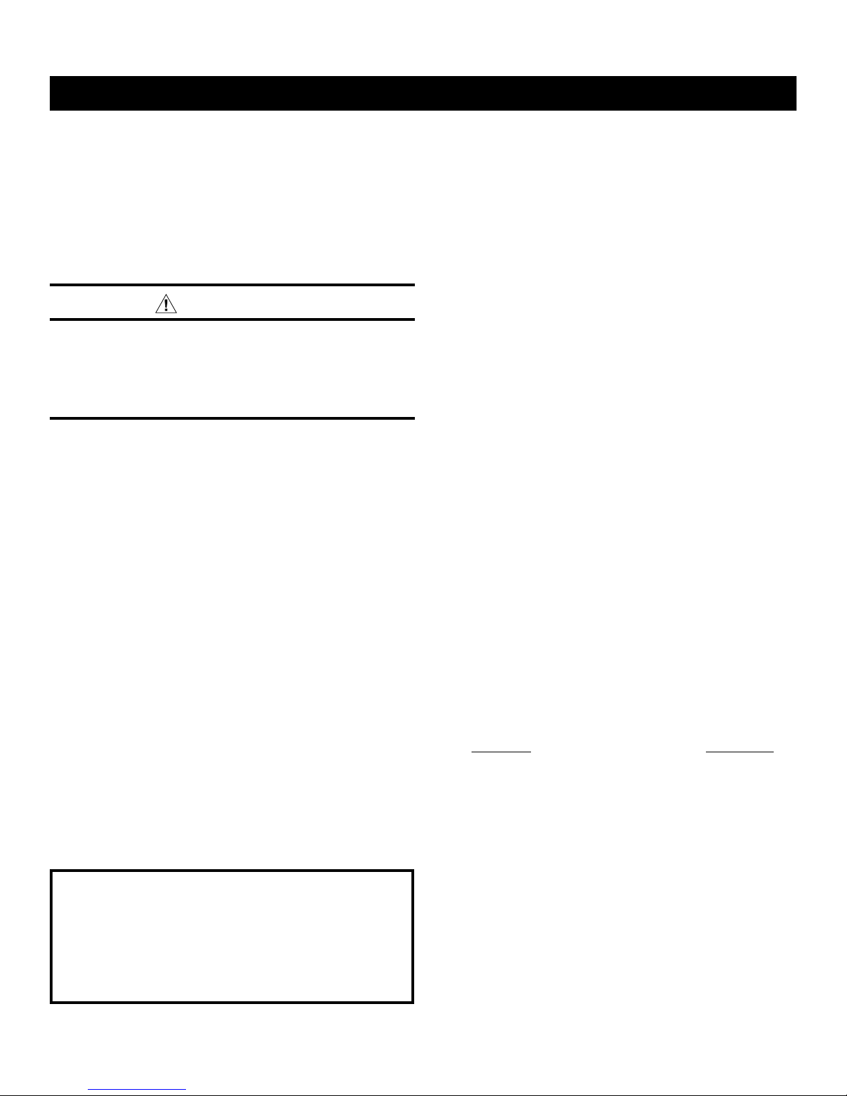
NOTE: Disassembly instructions may vary depending upon
the age and design of the roof jack. See Figure 1.
1. Disassemble the top roof jack by removing the screws
connecting it to the upper combustion air intake pipe.
2. Remove brackets from the combustion air intake upper pipe.
NOTE: The brackets are fastened with 1/8” pop rivets and
can be removed by drilling the rivets with a 1/8” drill bit.
3. Remove the inner and outer flue pipes (6” diameter) from
the roof jack.
Installing the Vent & Combustion Air Intake Pipe
(After the M3RL / M7RL furnace is set in place)
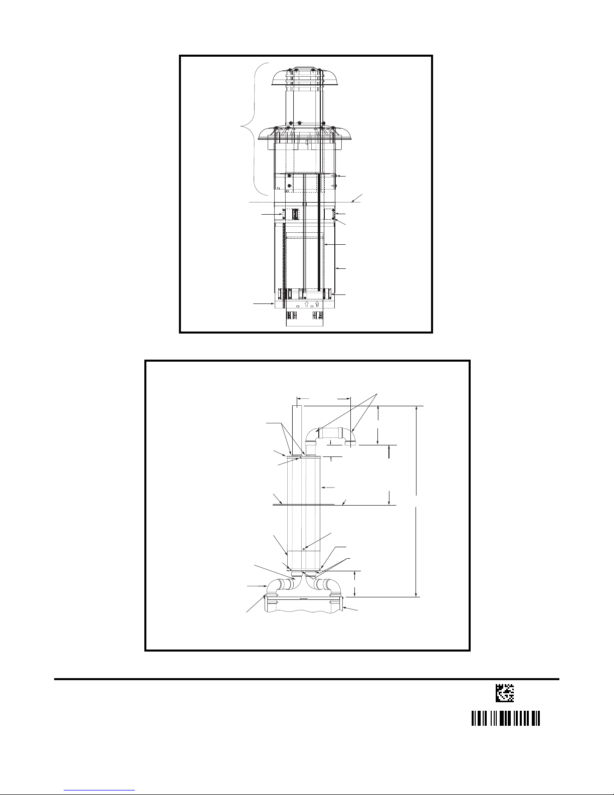
1. Refer to Table 2 and choose proper vent pipe material.
2. Install 2” rubber couplings on the furnace pipes and assemble
90º SPIG x HUB elbow (large radius). See Figure 2.
3. Place bottom and top replacement caps on the roof jack.
DO NOT screw the caps down at this time.
4. Cut 2” plastic pipes to length and route the vent and
combustion air intake pipes through the replacement caps.
NOTE: The maximum height from the top of the furnace
to the top of the flue pipe must be no longer than 15 feet.
See Figure 2.
IMPORTANT INFORMATION:
• Ventandcombustionairpipeandttingsmustbeone
of the materials listed below and must conform to the
indicated ANSI/ASTM standards.
• CementandprimermustconformtoATSMStandard
D2564 for PVC and Standard D2235 for ABS. When
joining PVC piping to ABS, use PVC solvent cement. In
Canada, cements, cleaners, or primers must be certified
as a system to ULC S636.
• Before permanentlyinstallingPVC components,itis
recommended you dry-fit them first to ensure proper
fit and alignment with other vent pipes.
INSTALLING THE KIT
1. Verify structural integrity of the roof flashing and upper and
lower combustion air pipes. NOTE: Do not use this kit with
existing roof jacks that are unsafe or unstable.
2. Replace the existing furnace with the new M3RL / M7RL
furnace. Refer to the the installation instructions supplied
with the furnace for additional information.
KIT CONTENTS
Replacement Vent Caps ...................................... Qty: 2
2" Rubber Couplings ............................................Qty: 2
2” Diameter Clamps ............................................. Qty: 4
90° Street Elbows ................................................ Qty: 2
#10 Sheet Metal Screws ......................................Qty: 6
Instruction sheet .................................................. Qty: 1
Table 1. Kit Contents
Materials Standards
Schedule 40PVC ........................................ D1785
PVC-DWV ................................................... D2665
SDR-21* & SDR-26* ................................... D2241
ABS-DWV ................................................... D2661
Schedule 40 ABS ....................................... F628
Foam/Cellular Core PVC ............................ F891
5. Permanently bond all PVC components together using
appropriate primer and cement.
6. Screw the top & the bottom replacement caps to the outer
pipes. NOTE: Two or more screws must be used on each cap.
7. Tighten the upper hose clamps on the 2” rubber couplings.
8. Secure the combustion air intake pipe to the lower
combustion air intake pipe at the bottom of the upper pipe
using at least two screws.
9. Seal around the two pipes on the top and bottom replacement
caps with silicone sealant.
Page 2
Top Roof
Jack Assy
Screws
Roof Flashing
Bracket
Lower Combustion
Air Intake Pipe
Figure 1. Typical Existing Roof Jack
Seal With
Silicone Sealant
Replacement Cap
Lower Vent
Chase Pipe
2" X 90o Elbow - Large
Radius Hub X Hub
(Both Sides)
2" X 90o Elbow - Large
Radius Spig X Hub
(Both Sides)
Screw
Roof
Flashing
Screw
Bracket
Rivets
Outer Flue
Pipe Assy
Upper Combustion
Air Intake Pipe
Bracket
5" to 13"
10" Min.
1" Min.
Upper Vent
Chase Pipe
(8" Dia.)
Add 2 or More Screws Thru
Upper & Lower Pipes to
Prevent Telescoping
above roof
or expected
snow level
Roof
Replacement Cap
Seal With
Silicone Sealant
8" Max.
2" X 90o Elbow
Large Radius
Hub x Hub 2 Req.
12” Min.
15' Max.
2" Dia. Rubber
(Both Sides)
Figure 2. Vent & Combustion Air Intake Pipe Installation
Specifications & illustrations subject to change without notice or incurring obligations (05/15).
O’Fallon, MO, © Nortek Global HVAC LLC 2015. All Rights Reserved.
Furnace
Coupling
7093520 (Replaces 708300B)
 Loading...