

Page 1
LiveSteam
Important: Read and save these instructions. This guide to be left with equipment owner.
Installation and
Operation Manual
Includes installation, operation
maintenance and troubleshooting
information for your LiveSteam
humidifier
1506160-B| 12 JUNE 2013
Page 2

Thank you for choosing Nortec.
INSTALLATION DATE (MM/DD/YYYY)
MODEL #
SERIAL #
CYLINDER #
Proprietary Notice
This document and the information disclosed herein are proprietary data of NORTEC HUMIDITY LTD. Neither
this document nor the information contained herein shall be reproduced, used, or disclosed to others without
the written authorization of NORTEC HUMIDITY LTD., except to the extent required for installation or
maintenance of recipient’s equipment. All references to the Nortec name should be taken as referring to
NORTEC HUMIDITY LTD.
Liability Notice
Nortec does not accept any liability for installations of humidity equipment installed by unqualified personnel or
the use of parts/components/equipment that are not authorized or approved by Nortec.
Copyright Notice
Copyright 2013, NORTEC HUMIDITY LTD. All rights reserved.
Page 3

Contents
2 Installation
2 Receiving & Unpacking
2 Location of the Humidifier in an Air Conditioning System
3 System 1 – Air Handling Unit
4 System 2 – In Duct Near An Elbow
5 System 3 – Multi-Zone System
6 System 4 – Dual Duct
6 System 5 – Primary and Secondary Distributors
7 Steam and Condensate Piping
7 Assembly of Single Distributor Humidifier
8 Assembly of Multiple Distributor Humidifier
9 Installation of LiveSteam Humidifier
10 Changing Orientation of Single Distributor Humidifier
10 Insulated Steam Distributors
10 Duct Support Bracket
12 Pressurized SAM-e
12 Plumbing
12 Installing Actuator to Steam Valve
23 SAM-e with Pressure Steam
23 Mini SAM-e with Pressurized Steam
27 Maintenance
27 Troubleshooting
Page 4

CAUTION: Servicing
Disconnect main power before any servicing.
The plumbing and electrical compartments contain high voltage components and
wiring. Access should be limited to authorized personnel only.
During and following operation of the humidifier, the steam and components in
contact with the steam such as the blower pack, steam lines, steam distributors,
and condensate lines can become hot and can burn if touched.
Walter Meier does not accept any liability for installations of humidity equipment
installed by unqualified personnel or the use of parts/components/equipment
that are not authorized or approved by Walter Meier.
CAUTION: Electrical
All electrical work should be done according to local and national electrical code.
Electrical connection to be performed by a licensed electrician.
CAUTION: Plumbing
Plumbing to be performed by a licensed plumber.
Drain water from humidifier can be very hot. Do not drain to public sink.
All plumbing work should be done according to local plumbing code.
CAUTION: Installation
Do not mount on hot surfaces.
Do not mount in area where freezing can occur.
Do not mount on vibrating surface.
Do not mount on floor.
LiveSteam produces steam at atmospheric pressure no devices which could block
steam output should be connected to the steam outlet.
Steam lines must be installed so that no restriction can produce backpressure in
the humidifier.
Regardless of selecting on/off or modulating control method, Nortec humidifiers
must have a closed circuit across its on/off security loop control terminal to
operate. Nortec highly recommends the use of a duct high limit humidistat.
1 | LS Installation Manual
Page 5
Installation
Velocity
Inlet Steam Pressure
Up Flow Distance
500
15
2 ft
1000
15
1 ft
500
30
4 ft
1000
30
2 ft
Receiving & Unpacking Equipment
1 Check packing slip to ensure ALL material has been delivered.
2 All material shortages are to be reported to Nortec within 48 hours from receipt of goods.
Nortec assumes no responsibility for any material shortages beyond this period.
3 Inspect shipping boxes for damage and note damages on shipping waybill accordingly.
4 After unpacking, inspect equipment for damage and if damage is found, notify the shipper
promptly.
5 All Nortec products are shipped on an FOB factory basis. Any and all damage, breakage or
loss claims are to be made directly to the shipping company.
Location of the humidifier in an air conditioning system
Reference the following systems for humidifier location:
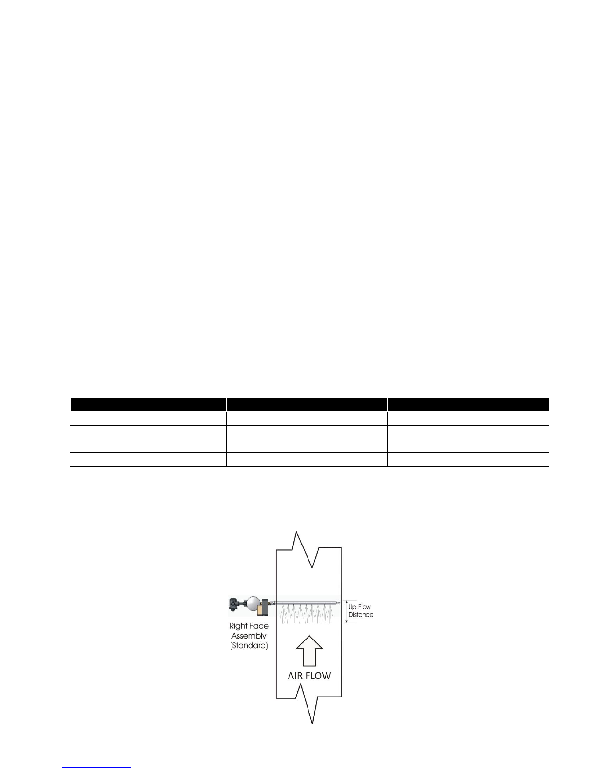
Up flow affect
The up flow affect is a result of the air velocity versus the steam velocity leaving the orifices of
the distributor.
The air velocity is a product of the volume flow rate through a present cross sectional area. The
steam velocity leaving the orifices is directly proportional on the internal pressure, inside the
distribution tube. This pressure is reduced when two or more distributors are in use.
The following up flow guidelines has been established from testing:
These up flow distances are only guidelines. Every application presents a multitude of variables
which may shorten or lengthen the up flow distance. The location of the distributor may need to
be changed if condensation occurs.
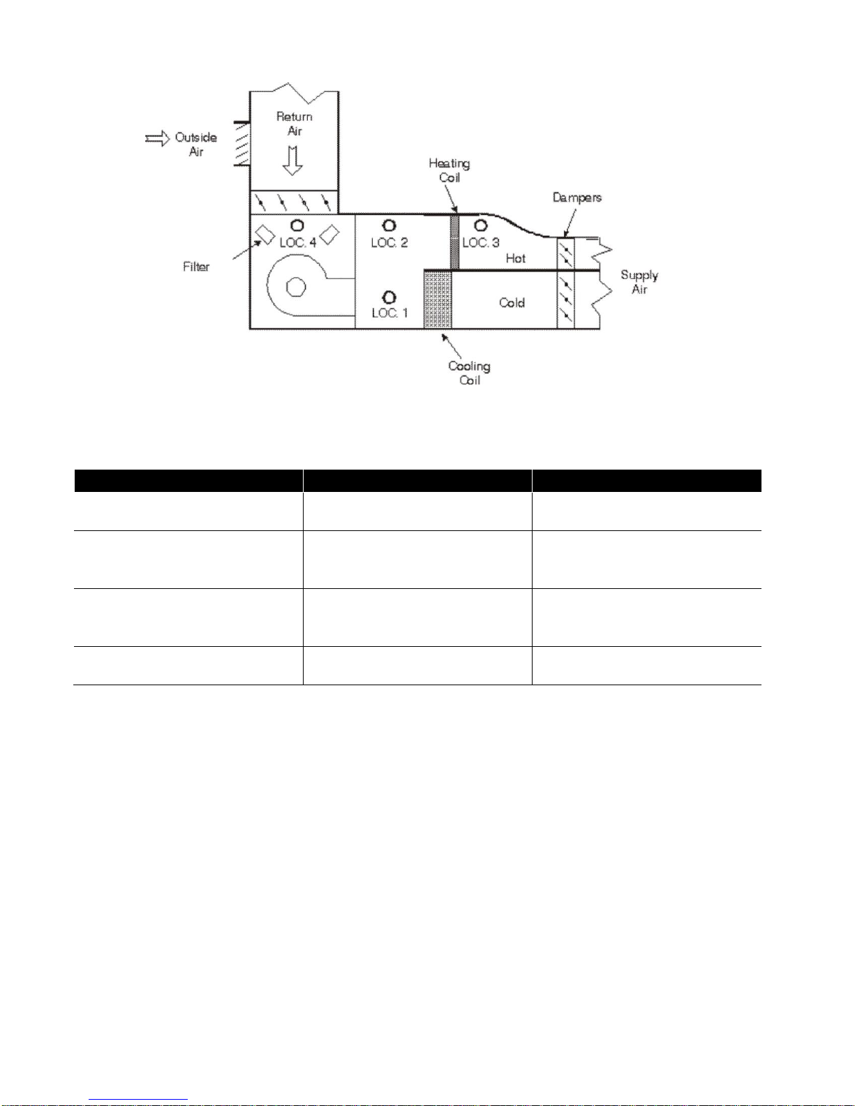
Figure 1: Top View
LS Installation Manual | 2
Page 6
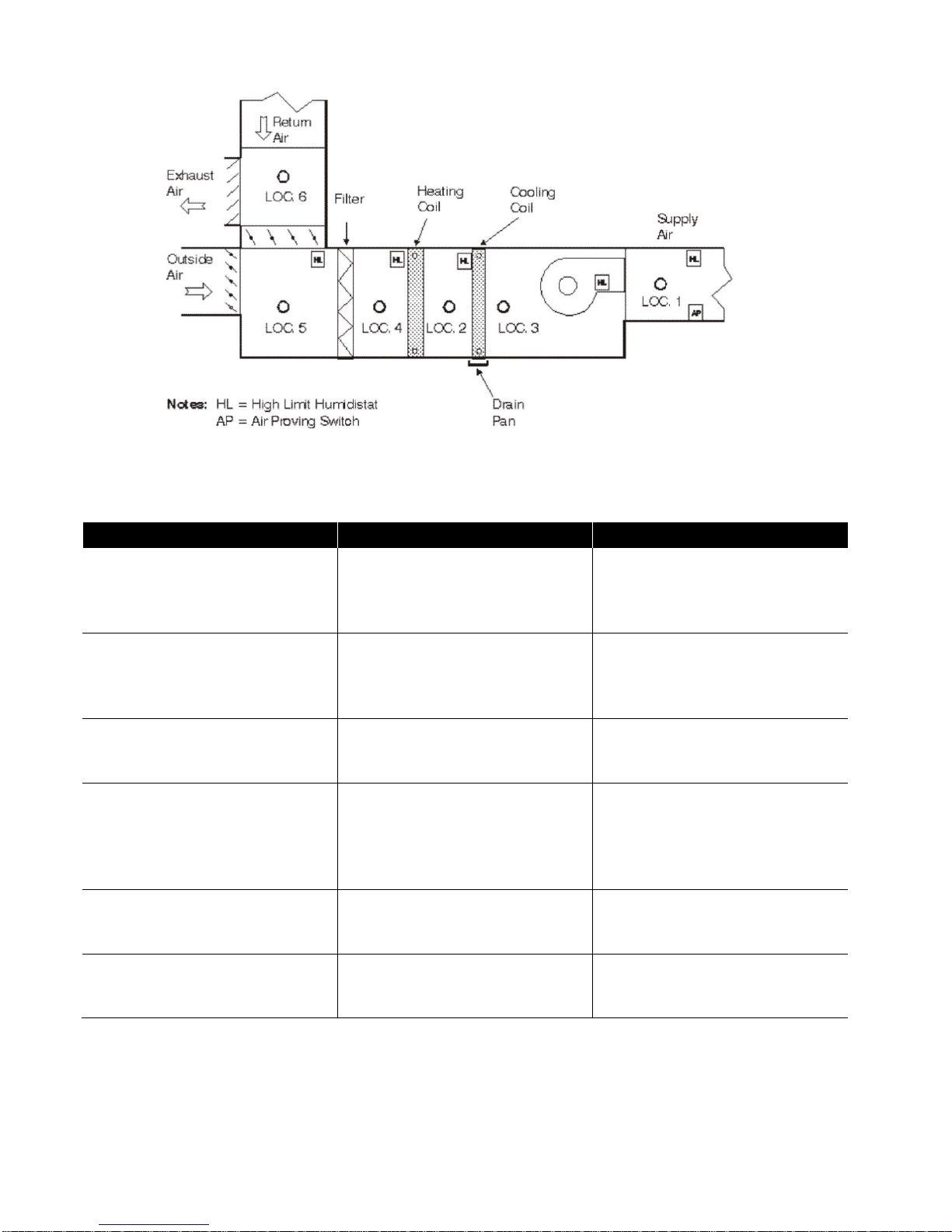
System 1 - Air Handling Unit
Location
Advantages
Disadvantages
LOC. 1
MOST recommended.
Assuming there is
sufficient straight duct for
absorption.
High velocity may create long
absorption distances.
LOC. 2
Warm air from heating coil.
Good absorption will help
evaporate steam.
Cooling coils designed for
water.
Possible capacity drop due to
condensation on the coil.
LOC. 3
Warm air.
Good absorption.
If absorption distance is too
long it may wet the fan.
LOC. 4
Heating coils will help
evaporate steam.
Air is mixed well.
Absorption may be a problem.
No drain pan on heating coil.
Cold air.
LOC. 5
Not Recommended.
Filters may get saturated.
Cold air.
LOC. 6
Not Recommended.
Outside air may cause
condensation problems.
Problematic RH control.
Figure 2: Air Handling Unit
Table 1: Air Handling Unit
3 | LS Installation Manual
Page 7
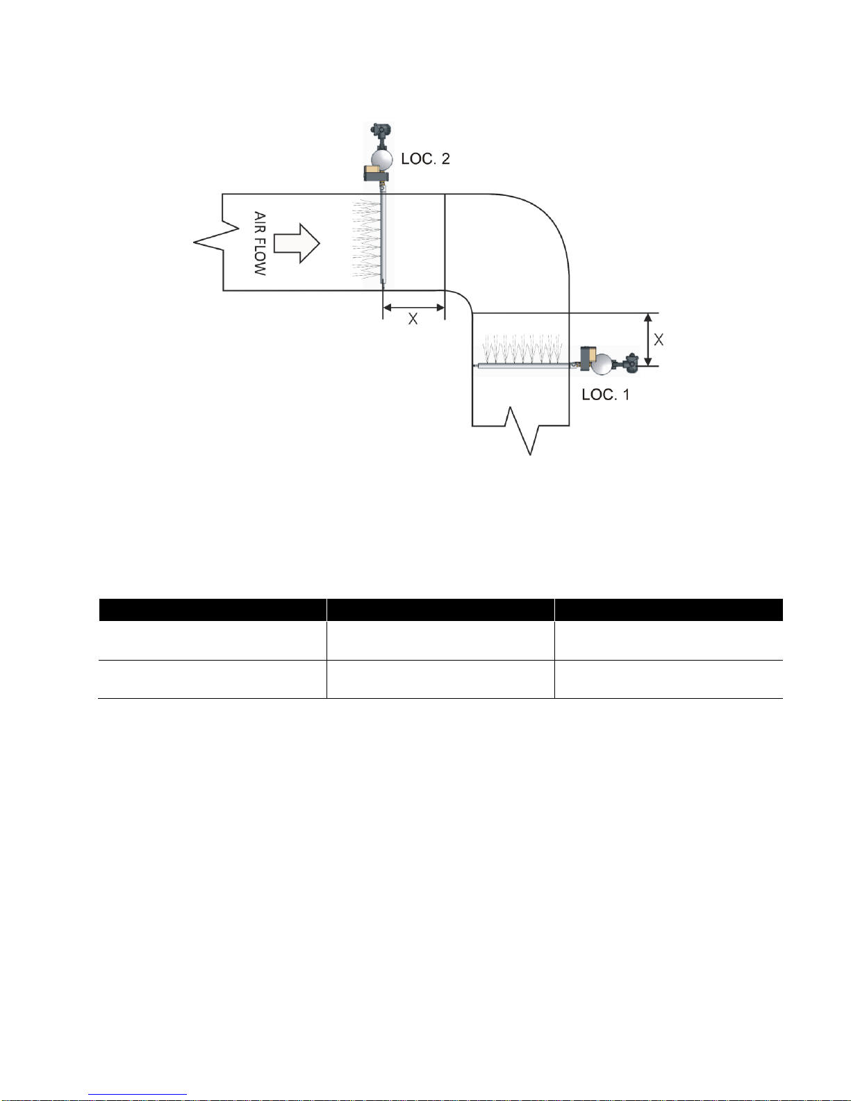
System 2 - In Duct Near An Elbow
Location
Advantages
Disadvantages
LOC. 1
MOST recommended. More
air on the outside of the turn.
Uneven air flow in the duct.
LOC. 2
Even air flow over the whole
duct.
Possibility of wetting of the
turning vanes.
Note: If not calculated, dimension “X” is minimum 6’ before or after bend or transition. See up flow
effect on page 6 for calculation.
Figure 3: In Duct Near An Elbow
Table 2: In Duct Near An Elbow
Warning: This type of distributor may produce a whistling noise as the pressurized steam decompresses
within the distributor and is introduced into the airstream. This noise may be increased with higher
pressure applications. For noise dampening recommendations, please consult the factory.
LS Installation Manual | 4
Page 8
System 3 - Multi-Zone System
Location
Advantages
Disadvantages
LOC. 1
Maximum absorption distance
to dampers.
Possible loss of capacity to
condensate on cooling coils.
LOC. 2
Heating coil will help absorb
steam.
Minimum distance to the
dampers could result in
wetting.
LOC. 3
Warm air.
Minimum distance to the
dampers could result in
wetting.
LOC. 4
Not recommended.
Filters may get saturated.
Cold air.
Figure 4: Multi-zone System
Figure 3: Multi-zone System
If one zone requires most of the air quantity supplied to the system, this zone should be the
location for the humidifier. Humidity will eventually equalize when the system has been in
operation for a while.
5 | LS Installation Manual
Page 9

System 4 - Dual Duct
Figure 5: Dual Duct
This system usually requires two steam distributors. The primary load (LOC.1) will go upstream
of the fan. The humidistat is located after the fan and before the hot and cold decks. The
secondary load (LOC. 2) will go downstream to the mixing boxes and will be controlled by a
humidistat in the space. Please consult your Nortec agent if absorption distance is a problem.
High limit humidistat is recommended in the mixed air duct.
System 5 - Primary And Secondary Distributors
Figure 6: Primary and Secondary Distributors
On occasion you may need a secondary load to reach a higher RH level in one part of your
operation (i.e. Hospitals). In this case, the primary load will maintain the normal space
condition (70°F at 35% RH) and the secondary load will satisfy the higher RH level (70°F at
45% RH) needed for that zone. High limit humidistats are recommended for each duct.
LS Installation Manual | 6
Page 10
Steam and Condensate Piping
1 Steam supply must be taken from the top of the main supply to the humidifier. Do not take
from the sides or the bottom. See Figure 8.
2 For removal of condensate from the steam trap the condensate line should not be under
pressure. Nortec recommends a check valve be installed after the steam trap if the
condensate return line is pressurized.
3 Proper design and sizing of steam supply lines should be performed by a qualified firm.
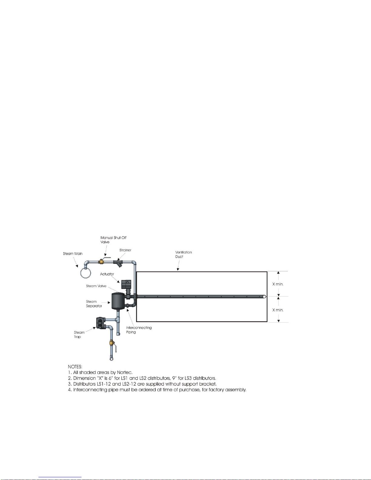
Assembly Of Single Distributor Humidifier
Note: Follow all general instructions provided with valve and actuator.
All single distributor humidifiers will be assembled at the factory if the interconnecting piping
option is selected at time of order.
1 Match the separator/valve assembly with the correct distributor assembly (Nortec will tag
both assemblies).
2 The o-ring in the tube adaptor should be lubricated (use silicone based lubricant).
3 Slide the distributor into the tube adapter. Make sure that the o-ring is not damaged.
Tighten tube adapter. The adapter should be hand tightened plus ¼ turn (25 in-lbs ± 5 inlbs).
4 The union halves come together and are tightened to make a snug fit. The humidifier is
ready to be installed in the duct. Single tube comes factory assembled, multi-tube must be
field assembled.
7 | LS Installation Manual
Figure 7: Single Distributor Humidifier
Page 11
5 It is also possible to install distributor in the duct and then attach the separator/valve
assembly.
6 Follow the steps listed in “Installation Of LiveSteam Humidifier” section to complete
installation.
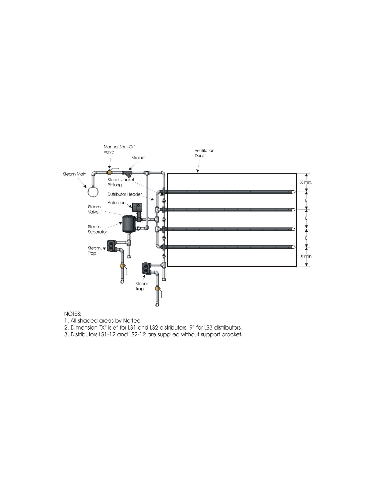
Assembly Of Multiple Distributor Humidifier
Make a plan of distributors’ layout (if not already done). See Figure 8. Multiple distributor
humidifiers require field assembly. The following steps should be taken into consideration:
1 Match the separator valve assembly with the correct distributors (Nortec will tag both
assemblies).
2 To ensure the same output from each dispersion tube, connect steam supply from separator
close to the middle of distributor header.
3 Steam jacket piping has to be secured to the distributor header to avoid possible
separation. Use gear clamp or similar device.
4 Distributors have to be equally spaced in the duct. Distance to the top and bottom of the
duct should be one half of “E” but not less than 6" for LS1 and LS2 distributors and not less
than 9" for LS3 distributors.
5 Use additional steam trap if total length of distributors of Type LS1 exceeds 40’, Type LS2
exceeds 30’, and Type LS3 exceeds 20’. See Figure 9.
Figure 8: Multiple Distributor Humidifier
LS Installation Manual | 8
Page 12
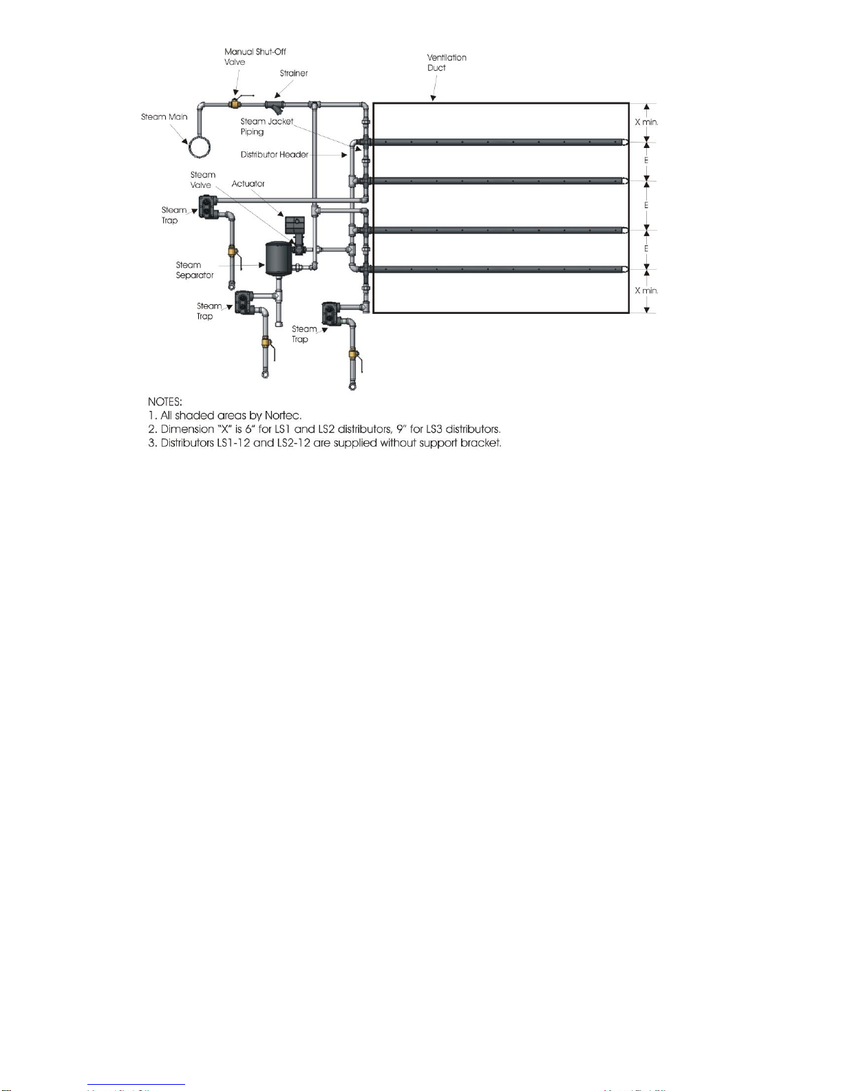
Figure 9: Multiple Distributor Humidifier with Multiple Traps
6 Follow the steps listed in “Installation Of LiveSteam Humidifier” section to complete
installation.
Installation Of Livesteam Humidifier
Note: Follow all general instructions provided with valve and actuator.
To complete installation follow the steps listed below.
1 Steam outlets of distributor should face into the air stream unless distributor is insulated.
Nortec’s standard is right face.
2 Distributors must be mounted level. There is a support bracket at the end of the distributor
to secure to the duct wall. See Figure 11 to 14 for installation tips.
3 The steam distributor in a Single Distributor Humidifier should be centered in the duct.
4 The steam distributor should be mounted in a straight section of duct. Please consult your
Nortec agent if absorption distance is a problem. For calculation of absorption distance
please refer to Nortec manual Form #163D.
5 Do not locate the steam distributor within 10 feet of high efficiency filters, otherwise the
filter will become saturated.
6 Cut a hole in the side of the duct large enough to insert the steam distributor. Duct plates
are provided to seal any opening.
7 Install actuator. During installation follow instructions shipped with actuator.
8 For ease of maintenance, provide shut-off a valve before humidifier (between strainer and
steam main). It can also be used to minimize heat gains during the non-humidification
period.
9 Install strainer before entering system and steam trap. Connect to steam and condensate
return mains.
9 | LS Installation Manual
Page 13

Right Face
Assembly
(Standard)
Left Face
Assembly
10 Wire (electric) or install control tubing (pneumatic) to the valve actuator.
11 Industry standards recommend the use of drain pans under the steam distributor.
12 Nortec recommends the use of a temperature switch. Valve will not open until the
distributor has reached its operating temperature. This is optional and must be ordered.
13 Nortec recommends the use of an air proving switch to prevent wetting in the duct.
Humidifier will not operate if there is no air movement in the duct.
14 A high limit duct humidistat, which prevents saturation and wetting in the duct, is
recommended downstream 12-14 feet from the humidifier and set at 80 to 90% RH.
Changing Orientation Of Single Distributor Humidifier
Unless otherwise specified at the time of order placement, all uninsulated single tube
distributors will be shipped with right face assembly and steam outlets facing the air stream
(See Figure 10). The steam flow direction can be changed by opening the union and
disengaging the nipple / elbow assembly from the steam distributor, turning the tube assembly
180º and reinstalling the nipple / elbow assembly.
Warning: LS distributors are designed to be supported by the steam piping connected to the
unit. Failure to properly support steam piping can result in stresses on the tube adapter and
damage the o-ring.
Insulated Steam Distributors
When the steam distributor is insulated the distributor should discharge in the direction of air
flow. This is to prevent condensation build-up on the steel insulation jacket.
Duct Support Bracket
Duct support bracket allows for easy installation in the various duct configurations (Figure
#11,12,13,14).
It is designed to be used with maximum bolt size of 3/8" (M10). LS1 and LS2 distributors that
are 12” (30.5 cm) long are not supplied with duct support brackets.
Figure 10: Right / Left Face Assembly
LS Installation Manual | 10
Page 14

Figure 11: Duct Support Bracket Flush with Duct Wall
Figure 12: Duct Support Bracket Away from Duct Wall
Figure 13: Duct Support Bracket with Angled Duct Wall
11 | LS Installation Manual
Page 15

Dura Drive P/N
Nortec P/N
Assembly Instructions
MS51-7203 DURA
DRIVE ACTUATOR
150 7552 0-10VDC,
150 7553 4-20mA,
150 7554 On/Off
For 1-1/2” Bronze Valve for incoming pressures
from 35 to 50 psi, and 2” Bronze Valve for
incoming pressures from 20 to 50 psi.
Warning: Proper design and sizing of steam lines should be performed by a qualified
technician.
Figure 14: Duct Support Bracket with Horizontal Duct Wall
Pressurized SAM-e
Plumbing
Steam Line
Condensate Return Line
When pressurized steam (2-50 psi) enters the SAM-e, steam expansion reduces pressure down
to almost atmospheric pressure. Therefore condensate cannot be lifted after the F+T trap. A
high temperature condensate pump may be used to achieve this.
Condensate from the SAM-e must always be returned to an atmospheric condensate return
main.
Long condensate runs (more than 20 ft.) should be oversized for better flow. Refer to Figure 33
and 34.
For proper trap installation, refer to Figure 15.
Installing Actuator To Steam Valve
LS Installation Manual | 12
Page 16

13 | LS Installation Manual
Page 17

Step 1
Ensure all components are
accounted for:
1. Connecting Pin
2. Stem Extension
3. Set Screw
4. Lock Washer
5. Jam Nut
6. Actuator
Figure 15: Step 1
Step 2
1. Thread jam nut on to valve
stem all the way.
2. Place lock washer over valve
stem so that it seats against jam
nut.
3. Thread stem extension on
valve stem compressing the lock
washer.
Figure 16: Step 2
ASSEMBLY INSTRUCTIONS
LS Installation Manual | 14
Page 18

Step 3
1. Insert hex wrench as
illustrated.
2. Rotate wrench 1 ½ turns
counter-clockwise.
3. Lock actuator by tightening
locking mechanism with a slotted
screwdriver.
Figure 17: Step 3
Step 4
1. Thread actuator on to valve.
2. Tighten valve mounting nut.
3. Manually raise valve stem to
up position (Closed).
Figure 18: Step 4
Step 5
1. Align stem extension hole with
actuator plunger hole.
2. Insert connecting pin.
3. Tighten jam nut against valve
stem.
4. Insert set screw into actuator
on most accessible side.
5. Tighten 20-25 in./lbs.
Figure 19: Step 5
Step 6
1. Release actuator by loosening locking mechanism.
2. Refer to wiring diagram for wiring instructions.
3. Apply power to actuator and ensure proper operation of valve and actuator.
4. Ensure proper response to control signal. 5. The actuator should be putting tension on the
stem and holding it closed (up position).
15 | LS Installation Manual
Page 19

Dura Drive P/N
Nortec P/N
Assembly Instructions
MS51-7103 DURA
DRIVE ACTUATOR
150 7549 0-10VDC,
150 7550 4-20mA,
1507551 On/Off
For Bronze ½”- 2” and St. St. ½”- 3/4” Valves,
for incoming pressures from 2 to 50 psi for all
valves except for 1-1/2” which would be 2 to
34 psi, and 2” which would be 2 to 19 psi
Step 1
Ensure all components are
accounted for:
1. Connecting pin
2. Stem Extension
3. Jam Nut
4. Actuator
Figure 20: Step 1
Step 2
1. Thread jam nut on to valve
stem all the way.
2. Thread stem extension on valve
stem.
3. Manually raise valve stem to up
position (Closed).
Figure 21: Step 2
LS Installation Manual | 16
Page 20

Step 3
1. Insert hex wrench as
illustrated.
2. Rotate wrench 2 turns counterclockwise.
3. Lock actuator by pressing
wrench towards actuator and
rotating 1/8 turn clockwise.
Figure 22: Step 3
Step 4
1. Thread actuator on to valve.
2. Tighten valve mounting nut.
Figure 23: Step 4
Step 5
1. Align stem extension hole with
actuator shaft hole.
2. Insert connecting pin.
3. Tighten jam nut against valve
stem.
4. Release Actuator by turning
hex key 1/8 turn counterclockwise.
5. The actuator should be putting
tension on the stem and holding it
closed (up position).
Figure 24: Step 5
17 | LS Installation Manual
Page 21

Dura Drive P/N
Nortec P/N
Assembly Instructions
MS61-7203 DURA
DRIVE ACTUATOR
150 7556 0-10VDC,
150 7557 4-20mA,
150 7558 On/Off
For 1”- 2” St. St. Valves, for incoming pressures
from 2 to 50 psi
Step 1
Ensure all components are
accounted for:
1. Actuator
2. Hex Wrench
3. Stem Extension Kit
4. Linkage Assembly
Figure 25: Step 1
Step 2
Linkage Kit Includes:
1. Connecting Pin
2. Stem Extension
3. Large Lock Washer
4. Small Lock Washer
5. Nut (Not Used)
6. Sticker
Figure 25: Step 1
Step 6
1. Refer to wiring diagram for wiring instructions.
2. Apply power to actuator and ensure proper operation of valve and actuator.
3. Ensure proper response to control signal.
LS Installation Manual | 18
Page 22

Step 3
Stem Extension Kit Includes:
1. Spacer
2. Stem Extender
3. Valve Mounting Nut
4. Copper Ring (not used)
5. Lock Washer
Figure 26: Step 3
Step 4
Thread the two stem extensions
together with the lock washer as
shown in the illustration.
Figure 27: Step 4
Step 5
1. Thread the spacer on to the
valve.
2. Tighten the spacer as far down
as possible.
Figure 28: Step 5
19 | LS Installation Manual
Page 23

Step 6
1. Thread Extension Assembly
from Step 4 on to valve stem.
2. Hand tighten as far down as
possible.
3. Manually position the valve in
the fully open position.
Figure 29: Step 6
Step 7
Pre-loading Actuator:
1. Insert Hex wrench as
illustrated.
2. Rotate 1 ½ turns counterclockwise.
3. Lock Actuator by turning
locking mechanism clockwise with
a slotted screwdriver.
Figure 30: Step 7
LS Installation Manual | 20
Page 24

Step 8
1. Insert valve with extension into
actuator.
2. Loosely thread Valve Mounting
Nut and Lock Washer on to
Spacer as illustrated.
3. Adjust Stem Extension by
rotating to align holes on valve
stem extension and actuator.
Figure 31: Step 8
Step 9
1. Insert Connecting Pin through
hole in Stem Extension and
actuator plunger.
Figure 32: Step 9
21 | LS Installation Manual
Page 25

Step 10
1. Tighten Valve Mounting Nut
compressing Lock Washer.
2. Tighten Stainless Steel Jam
Nut on actuator against the
Spacer.
Figure 33: Step 10
Step 11
1. Release actuator by loosening locking mechanism.
2. Refer to wiring diagram for wiring instructions.
3. Apply power to actuator and ensure proper operation of valve and actuator.
4. Ensure proper response to control signal.
5. The actuator should be putting tension on the stem and holding it closed (up position)
LS Installation Manual | 22
Page 26

23 | LS Installation Manual
Page 27

LS Installation Manual | 24
Page 28

Strainer
Manual Shut-Off
Valve (By Others)
Pressurized
Steam Main
F & T Steam Trap
Duct/AHU Width
Duct/AHU
Height
Separator
Actuator & Valve
Pressurized condensate
return main
1” Air Gap
Drain
Manual Shut-Off
Valve (By Others)
6” min.
6” Min
Return to non-pressurized
condensate return main
Tap steam from top of
pressurized steam main
• Steam components in grey are provided by Nortec.
• Tap steam from top of pressurize steam main to avoid excess condensate.
• Condensate from separator to be returned to pressurized condensate main.
• Condensate from SAM-e to be returned to atmospheric floor drain.
When pressurized steam enters the SAM-e, the pressure drops down to almost atmospheric
pressure. Therefore, it must be drained atmospherically, and the use of a condensate pump
(rated for 212ºF) must be used to raise the condensate to a higher elevation.
SAM-e with Pressure Steam
Pressurized Plumbing with External Separator
25 | LS Installation Manual
Page 29

1” A ir Gap
Drain
Strainer
Manual Shut-Off
Valve (By Others)
Pressurized
Steam Main
6” min.
Return to non-pressurized
floor drain
Pressurized condensate
return main
Tap steam from top of
pressurized steam main
Note: The SAM-e header functions as a steam separator, therefore an external
steam separator is not required.
• Steam components in grey are provided by Nortec.
• Tap steam from top of pressurize steam main to avoid excess condensate.
• Condensate from SAM-e to be returned to atmospheric floor drain.
When pressurized steam enters the SAM-e, the pressure drops down to almost atmospheric
pressure. Therefore, it must be drained atmospherically, and the use of a condensate pump
(rated for 212ºF) must be used to raise the condensate to a higher elevation.
Pressurized Plumbing without External Separator
LS Installation Manual | 26
Page 30

Strainer
Manual Shut-Off
Valve (By Others)
Steam Main
F & T Steam Trap
Separator
Actuator & Valve
Pressurized condensate
return main
1” A ir Gap
Drain
Steam from top of main
Manual Shut-Off
Valve (By Others)
6” min.
6” min
Return to non-pressurized
condensate return main
Duct Width
Duct
Height
Duct Floor
Mounting
bracket
• Steam components in grey are provided by Nortec.
• Tap steam from top of pressurize steam main to avoid excess condensate.
• Condensate from separator to be returned to pressurized condensate main.
• Condensate from SAM-e to be returned to atmospheric floor drain.
When pressurized steam enters the SAM-e, the pressure drops down to almost atmospheric
pressure. Therefore, it must be drained atmospherically, and the use of a condensate pump
(rated for 212ºF) must be used to raise the condensate to a higher elevation.
Mini SAM-e with Pressurized Steam
Mini SAM-e Pressurized with External Separator
27 | LS Installation Manual
Page 31

Mini SAM-e Pressurized without External Separator
Strainer
Manual Shut-Off
Valve (By Others)
Steam Main
1” A ir Gap
Drain
Steam from top of main
6” min.
Return to non-pressurized
condensate return main
Pressurized condensate
return main
• Max steam pressure of 15 psig when no separator is used.
• Steam components in grey are provided by Nortec.
• Tap steam from top of pressurize steam main to avoid excess condensate.
• Condensate from separator to be returned to pressurized condensate main.
• Condensate from SAM-e to be returned to atmospheric floor drain.
When pressurized steam enters the SAM-e, the pressure drops down to almost atmospheric
pressure. Therefore, it must be drained atmospherically, and the use of a condensate pump
(rated for 212ºF) must be used to raise the condensate to a higher elevation.
LS Installation Manual | 28
Page 32

Maintenance
Elements Of LiveSteam Humidifier
Tube Adapter - consists of 3 pieces (See Figure 35). To maintain proper seal hand tighten tube
adapter nut, plus ¼ turn. Additional o-ring is shipped with this manual. If o-ring has to be
replaced do so as follows:
1. Disconnect actuator.
2. Dismount union by the separator.
3. Replace o-ring in the tube adapter.
4. Lubricate o-ring with silicone based lubricant.
Figure 35: Adapter Assembly
Strainer - Should be cleaned shortly after the system has begun operating (3 to 7 days) and
then annually.
Separator - No maintenance required.
Distributor - No maintenance required.
Valve - Should be inspected annually to confirm that steam is not leaking from the stem
packing, and the valve closes tightly. Repack if necessary.
Valve Seat - Lap seat if necessary.
Pneumatic Actuator - Should be inspected annually to confirm that the diaphragm is not leaking
air, and the valve operates properly.
Electric Actuator - Should be inspected annually to confirm that the valve operates properly.
Steam Trap - Should be inspected annually. Clean and inspect seats and replace required
gaskets if necessary.
Temperature Switch - Should be inspected once a year to ensure proper operation. Test by
supplying steam, which should open at 200ºF.
29 | LS Installation Manual
Page 33

Maintenance Schedule
Date
Personnel
Description
Problem
Cause / Solution
Distributor Discharges Water
Condensate return line not draining:
1. Back pressure on condensate line.
2. Dirty steam trap - repair or replace.
3. Steam trap is wrong type.
Steam supply:
1. Steam pressure is too low (under 2 psi).
2. Steam main flooding due to boiler
discharging water with steam.
3. Steam supply not taken at top of main.
4. Distributor not level.
Troubleshooting Guide
LS Installation Manual | 30
Page 34

Humidifier Leaks Water From Tube Adapter
1. Tighten tube adaptor.
2. Defective o-ring in tube adapter - replace
o-ring.
3. Is the o-ring lubricated?
Over Humidifying
1. Valve stem adjusted too tight and sticking.
2. Valve spring broken.
3. Foreign matter is preventing the valve from
closing.
4. Valve is installed incorrectly.
5. Steam pressure exceeds rating of valve
spring.
6. Controller out of calibration.
Under Humidifying
1. Boiler pressure is inadequate.
2. Steam piping is either undersized or piped
incorrectly.
3. Strainer is plugged.
4. Valve is not fully opened. (Check for leaking
air in actuator.)
5. Humidifier is undersized.
6. Controller is out of calibration.
7. Excess amounts of outside air.
8. Open doors, window, loading / shipping
docks.
Humidity Swings
1. Controller is malfunctioning.
2. Poor location of humidity sensor.
3. Humidifier is oversized.
4. Boiler pressure swings too widely
5. Pressure reducing valve is not working
properly (if installed).
Spitting During Start-Up
1. Add temperature switch.
2. Are drip legs installed?
3. Was the piping supplied undersized?
4. Is the boiler carrying too much condensate?
5. Is the boiler undersized or does it have the
incorrect pressure?
Condensate In Duct
1. Mounting too close to devices (elbows,
dampers, etc.) in duct.
2. Duct surface temperature is too low.
3. Oversized humidifier.
4. Malfunctioning or lack of safety high limit
humidistat.
31 | LS Installation Manual
Page 35

Valve Cross Reference Table
Valve Body Part Number
Nortec PN
Size
Cv
VB-7263-04-31
1594300
0.5"
0.1
VB-7263-0-4-33
1594302
0.5"
0.22
VB-7263-0-4-1
1594304
0.5"
0.4
VB-7263-000-4-35
1594306
0.5"
0.75
VB-7263-0-4-2
1594310
0.5"
1.3
VB-7263-0-4-3
1594314
0.5"
2.2
VB-7263-000-4-38
1594316
0.5"
2.8
VB-7263-0-4-4
1594318
0.5"
4.4
VB-7263-0-4-5
1594322
0.75"
5.5
VB-7263-0-4-6
1594324
0.75"
7.5
VB-7263-0-4-7
1594330
1.0"
10
VB-7263-0-4-8
1594332
1.0"
12
VB-7263-0-4-9
1594341
1.25"
20
VB-7263-0-4-10
1594350
1.5"
28
VB-7263-0-4-11
1594360
2.0"
40
VBS-9263-0-6-31
1594201
0.5"
0.1
VBS-9263-0-6-33
1594203
0.5"
0.22
VBS-9263-0-6-01
1594205
0.5"
0.4
VBS-9263-0-6-35
1594206
0.5"
0.75
VBS-9263-0-6-36
1594207
0.5"
0.95
VBS-9263-0-6-02
1594208
0.5"
1.3
VBS-9263-6-0-37
1594209
0.5"
1.75
VBS-9263-0-6-03
1594210
0.5"
2.2
VBS-9263-0-6-38
1594211
0.5"
2.8
VBS-9263-0-6-04
1594213
0.5"
3.6
VBS-9263-0-6-45
1594221
0.75"
4.3
VBS-9263-0-6-05
1594222
0.75"
5
VBS-9263-0-6-06
1594223
0.75"
6.2
VA7006EC
1594432
1.0"
10
VA7008EC
1594440
1.5"
24
VA7009EC
1594450
2.0"
40
LS Installation Manual | 32
Page 36

Actuator Close-Off Pressure
1507549, 1507550, 1507551 - 1/2 to 2 in, SS 1/2 to 3/4 in
Valve
1/2"
3/4"
1"
1-1/4"
1-1/2"
1-3/4"
2"
Bronze
50 psig
(345 kPa)
50 psig
(345 kPa)
50 psig
(345 kPa)
50 psig
(345 kPa)
34 psig
(234 kPa)
N/A
19 psig
(131 kPa)
SST
50 psig
(345 kPa)
50 psig
(345 kPa)
N/A
N/A
N/A
N/A
N/A
1507552, 1507553, 1507554 - Bronze 2 in
Valve
1/2"
3/4"
1"
1-1/4"
1-1/2"
1-3/4"
2"
Bronze
N/A
N/A
N/A
N/A
50 psig
(345 kPa)
N/A
50 psig
(345 kPa)
1507556, 1507557, 1507558 - 1 to 2 in SS
Valve
1/2"
3/4"
1"
1-1/4"
1-1/2"
1-3/4"
2"
Warren SST
N/A
N/A
50 psig
(345 kPa)
N/A
50 psig
(345 kPa)
N/A
50 psig
(345 kPa)
33 | LS Installation Manual
Page 37

Warranty
Nortec Humidity Inc. and/or Nortec Humidity Ltd. (hereinafter collectively referred to as THE
COMPANY), warrant for a period of two years after installation or 30 months from
manufacturer’s ship date, whichever date is earlier, that THE COMPANY’s manufactured and
assembled products, not otherwise expressly warranted (with the exception of the cylinder), are
free from defects in material and workmanship. No warranty is made against corrosion,
deterioration, or suitability of substituted materials used as a result of compliance with
government regulations.
THE COMPANY’s obligations and liabilities under this warranty are limited to furnishing
replacement parts to the customer, F.O.B. THE COMPANY’s factory, providing the defective
part(s) is returned freight prepaid by the customer. Parts used for repairs are warranted for the
balance of the term of the warranty on the original humidifier or 90 days, whichever is longer.
The warranties set forth herein are in lieu of all other warranties expressed or implied by law. No
liability whatsoever shall be attached to THE COMPANY until said products have been paid for in
full and then said liability shall be limited to the original purchase price for the product. Any
further warranty must be in writing, signed by an officer of THE COMPANY.
THE COMPANY’s limited warranty on accessories, not of the companies manufacture, such as
controls, humidistats, pumps, etc. is limited to the warranty of the original equipment
manufacturer from date of original shipment of humidifier.
THE COMPANY makes no warranty and assumes no liability unless the equipment is installed in
strict accordance with a copy of the catalog and installation manual in effect at the date of
purchase and by a contractor approved by THE COMPANY to install such equipment.
THE COMPANY makes no warranty and assumes no liability whatsoever for consequential
damage or damage resulting directly from misapplication, incorrect sizing or lack of proper
maintenance of the equipment.
THE COMPANY makes no warranty and assumes no liability whatsoever for damage resulting
from freezing of the humidifier, supply lines, drain lines, or steam distribution systems.
THE COMPANY retains the right to change the design, specification and performance criteria of
its products without notice or obligation.
Page 38

U.S.A.
Certificate No. 002419
2700 90th St.
Sturtevant, WI 53177
835 Commerce Park Dr.
Ogdensburg, NY 13669-2209
CANADA
2740 Fenton Road
Ottawa, Ontario K1T 3T7
TEL: 1.866.NORTEC1
FAX: 613.822.7964
EMAIL: nortec@humidity.com
WEBSITE: www.humidity.com
 Loading...