

Page 1

Important: Read and save these instructions. This guide to be left with equipment.
2559106-D | 10 OCT 2014
LINKS XPS
MH
Installation and
Operation Manual
Includes installation, operation
maintenance and troubleshooting
information for your MHTC
Evaporative Media humidifier
Page 2

INSTALLATION DATE (MM/DD/YYYY)
MODEL #
SERIAL #
CYLINDER #
Thank you for choosing NORTEC.
Proprietary Notice
This document and the information disclosed herein are proprietary data of NORTEC HUMIDITY LTD. Neither
this document nor the information contained herein shall be reproduced used, or disclosed to others without
the written authorization of NORTEC HUMIDITY LTD., except to the extent required for installation or
maintenance of recipient’s equipment. All references to the NORTEC name should be taken as referring to
NORTEC HUMIDITY LTD.
Liability Notice
NORTEC does not accept any liability for installations of humidity equipment installed by unqualified personnel
or the use of parts/components/equipment that are not authorized or approved by NORTEC.
Copyright Notice
Copyright 2012, NORTEC HUMIDITY LTD. All rights reserved.
Page 3

Page 4

Contents
3 Multi Unit Systems
4 Installing Links XPS into the Control Cabinet
4 Mounting the Links XPS Assembly
7 Internal Wiring Connections
15 Configuring the Humidifiers
17 Wiring
19 Gateway Configuration
21 Changing Baud Rate (BACnet MSTP, Johnson N2, LonWorks)
23 Changing the IP Address (BACnet IP)
27 Network Integration
30 BACnet Pics and Bibs
30 Variable Definition
43 Start-up Checklist
44 Troubleshooting
44 Indicator Lights
50 Wiring Diagrams
Page 5

Protocol
BACnet MS/TP
BACnet / IP
Johnson N2
LonWorks
The MHTC Nortec Links XPS Option allows for the integration of a MHTC Series humidifier within
a BACnet, Johnson N2 or LonWorks network. This option features a gateway that has the
capability of converting information from the host Modbus protocol to a specified secondary
protocol.
The following protocol options are available, and must be specified at time of order:
Table 1: Protocol Options
Multi-Unit Systems (“Master/Slave”)
Up to 8 humidifiers can be chained and monitored through a single Links XPS package. In this
configuration, the unit with the Links XPS package is designated the “Master Unit”, while the
remaining 7 humidifiers are configured as “Slaves”. The master unit is connected to the
Building Management Systems (BMS). Each unit is separately addressed, it is possible to
monitor and control each unit individually.
Different networking configurations may be achieved depending on the type of network being
used. One networking example could have a Gateway installed inside the lead unit, which could
then be daisy-chained to successive units. In turn, the lead unit would connect to a Building
Management System (BMS) network via a shielded, twisted-pair connection. Please see wiring
section for additional detail. A second example could have a series of units directly connected
to an Ethernet network. This is only possible for BACnet communication and is essentially
referred to as a BACnet/IP configuration.
Links XPS for MHTC | 2
Page 6

Installing Links XPS into the Control Cabinet
If the Links XPS package was included with the original unit order, the necessary hardware will
have been factory mounted and wired into the MHTC control cabinet. In this case, please skip
ahead to the Wiring section for information on how to complete connections to the building
automation system.
If Links XPS is being retrofit, or added to an existing MHTC unit in the field, follow the steps
below prior to connecting wiring to the building automation system.
Mounting the Links XPS Assembly
Caution: Disconnect electrical power from humidifier before performing work inside control
cabinet.
Locate the MHTC control panel and turn the power switch to the off position. Ensure that the
power is also turned off at the breaker panel to prevent electrical shock. Open the control
cabinet by loosening the screws on the on right side of the cabinet and sliding the brass lock
clip out of the way.
MHTC ReFlow Models
1 Using the 4 plastic standoffs and plastic screws provided, attach the Links XPS module to
the steel back plate in the location shown in Figures 1and 2.
2 Secure the XPS transformer into the location shown in Figures 1 and 2. Use the two #6-32
thread cutting screws provided to secure the transformer in place.
3 Install the XPS Terminal strip onto the DIN rail at the bottom of the control cabinet as shown
in Figure 1. It may be necessary to remove one or both of the rail locks and shift the entire
control terminal strip over to accommodate the XPS terminal strip.
Note: The exact location the XPS transformer may vary depending on the revision of back plate.
Also, units produced before August 2011 may not have the holes for the XPS module and
transformer. These models will require new holes to be drilled during installation.
3 | Links XPS for MHTC
Page 7
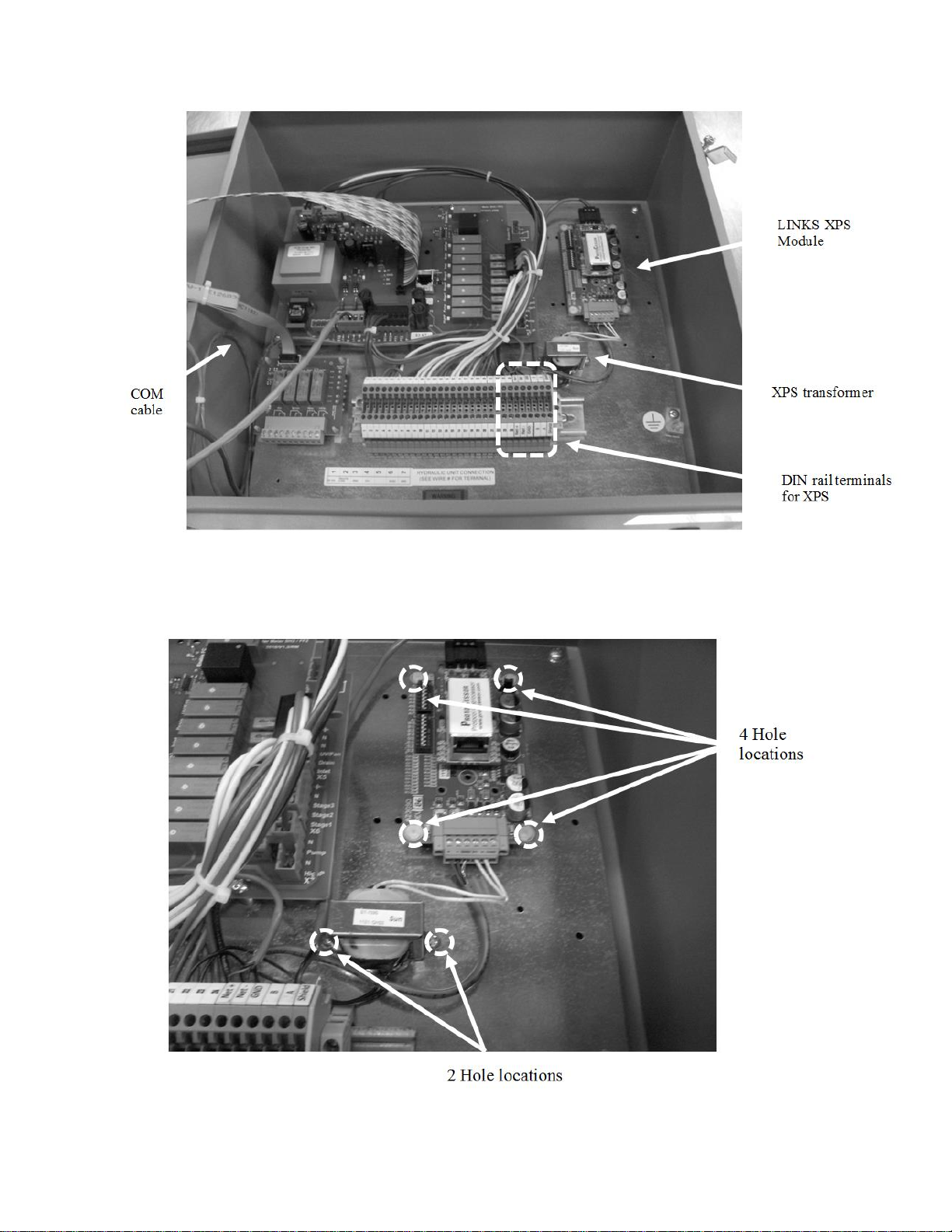
Figure 1: Component Identification
Figure 2: Component Hole Location
Links XPS for MHTC | 4
Page 8

MHTC Flow Models:
1 On MHTC Flow models, Links XPS replaces the remote fault relay board. Remove the
remote fault relay board indicated in Figure 3 and disconnect the cable.
Underneath the remote fault relay board, the 4 holes for the XPS module and two holes for
the XPS transformer should be visible. Depending on the revision of the backplate these
holes may be in different configurations or may not be present at all. In the case of the
latter, drill 4x ¼” holes to accommodate the XPS module. Subsequently drill 2x 9/64” holes
to accommodate the XPS transformer.
2 Using the 4 plastic standoffs and plastic screws provided, attach the Links XPS module to
the steel back plate.
3 Secure the XPS transformer using the two #6-32 thread cutting screws.
4 Install the XPS Terminal strip onto the DIN rail at the bottom of the control cabinet as shown
in Figure 1. It may be necessary to remove one or both of the rail locks and shift the entire
control terminal strip over to accommodate the XPS terminal strip.
5 | Links XPS for MHTC
Page 9
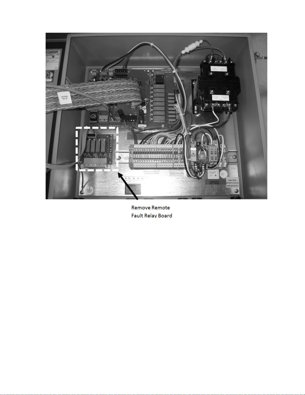
Figure 3: MHTC Flow Control Cabinet
Links XPS for MHTC | 6
Page 10
Internal Wiring Connections
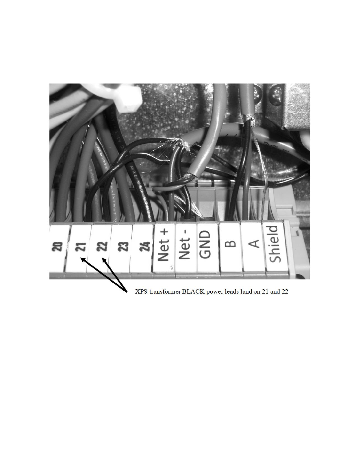
1 Connect the two black wires from the Links XPS transformer to the terminal 21 and 22 on
the MHTC control panel as shown in Figure 4. These wires are not polarity sensitive.
7 | Links XPS for MHTC
Figure 4: Transformer Power Connections
Page 11
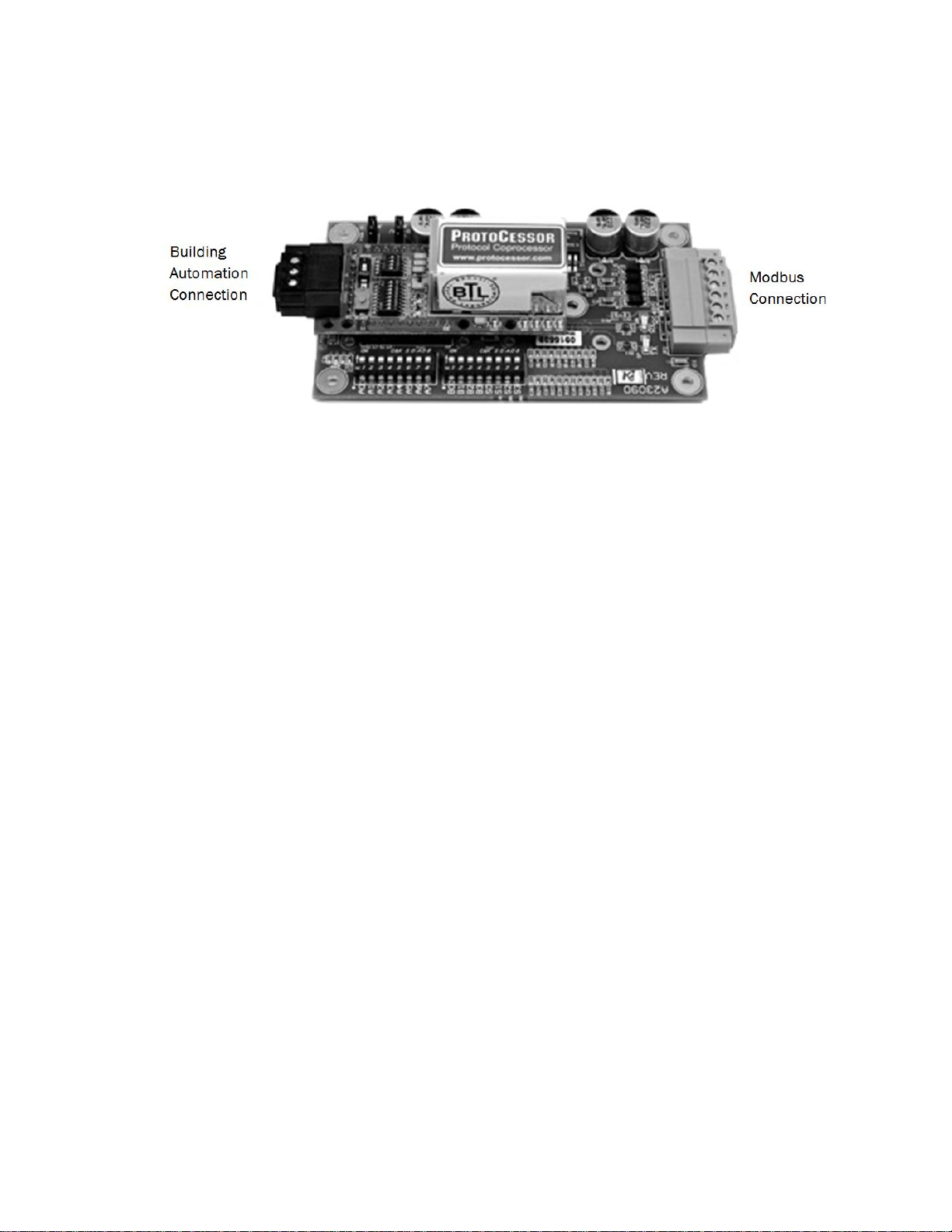
2 Identify the Modbus and Building Automation System ends on the XPS module.
Figure 5: Communication Ports XPS Module
3 Connect the two white wires from the transformer to the power terminals on the Modbus end
of XPS module as shown in Figure 5. Also, connect one of the two short grey 3-wire cables into
the +, -, and GND terminals on the XPS module as shown in Figure 5.
Links XPS for MHTC | 8
Page 12
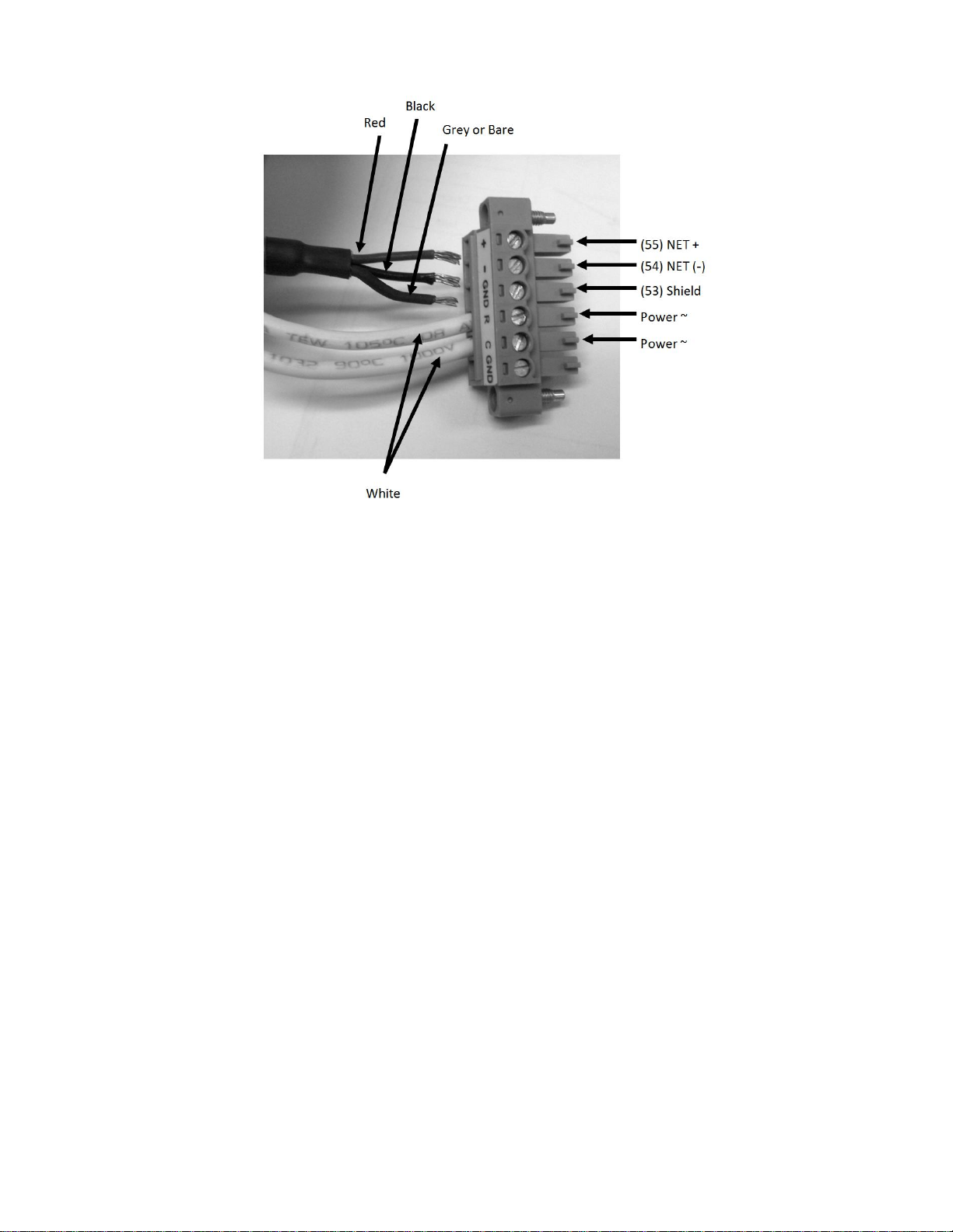
Figure 6: Links XPS Lonworks Module Terminals
4 Connect the other end of the short grey 3-wire cable from step 3 into the Net+, Net-, and
GND terminals on the DIN rail. The red cable should be connected to the Net + terminal, the
black to the Net - terminal, and grey/bare to the GND terminal. Refer to Figure 6.
9 | Links XPS for MHTC
Page 13
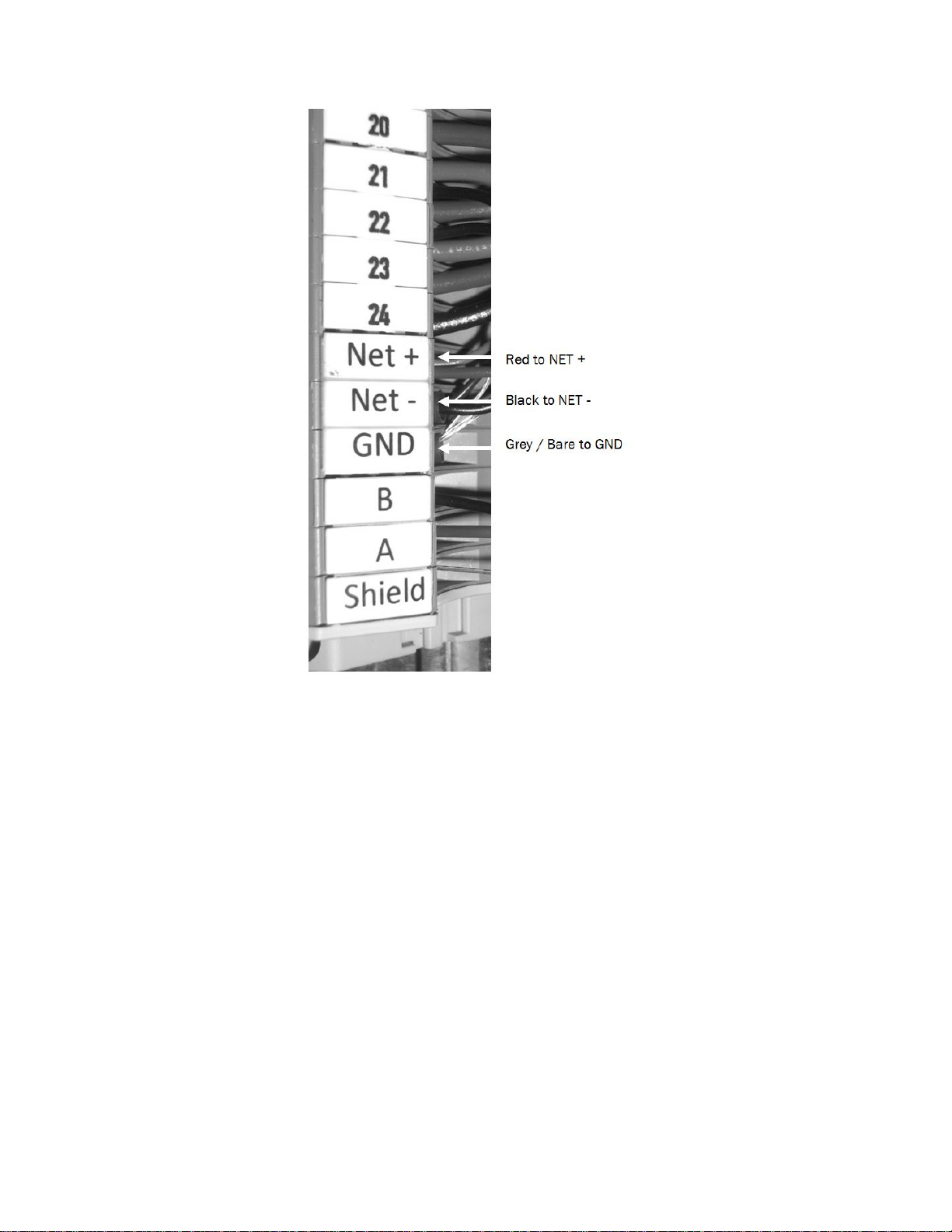
Figure 7: Communication Connections
5 Locate the long grey 3-wire cable with the RJ-45 plug on one end. Connect the wire end of
this cable into the Net+, Net -, and GND terminals used in step 4. The red cable should be
connected to the Net + terminal, the black to the Net - terminal, and grey/bare to the GND
terminal. These wires can either be “doubled up” with the cable from step 4 or installed on the
opposing side of the DIN rail. The cable, shown “doubled up”, is depicted in Figure 6.
Links XPS for MHTC | 10
Page 14
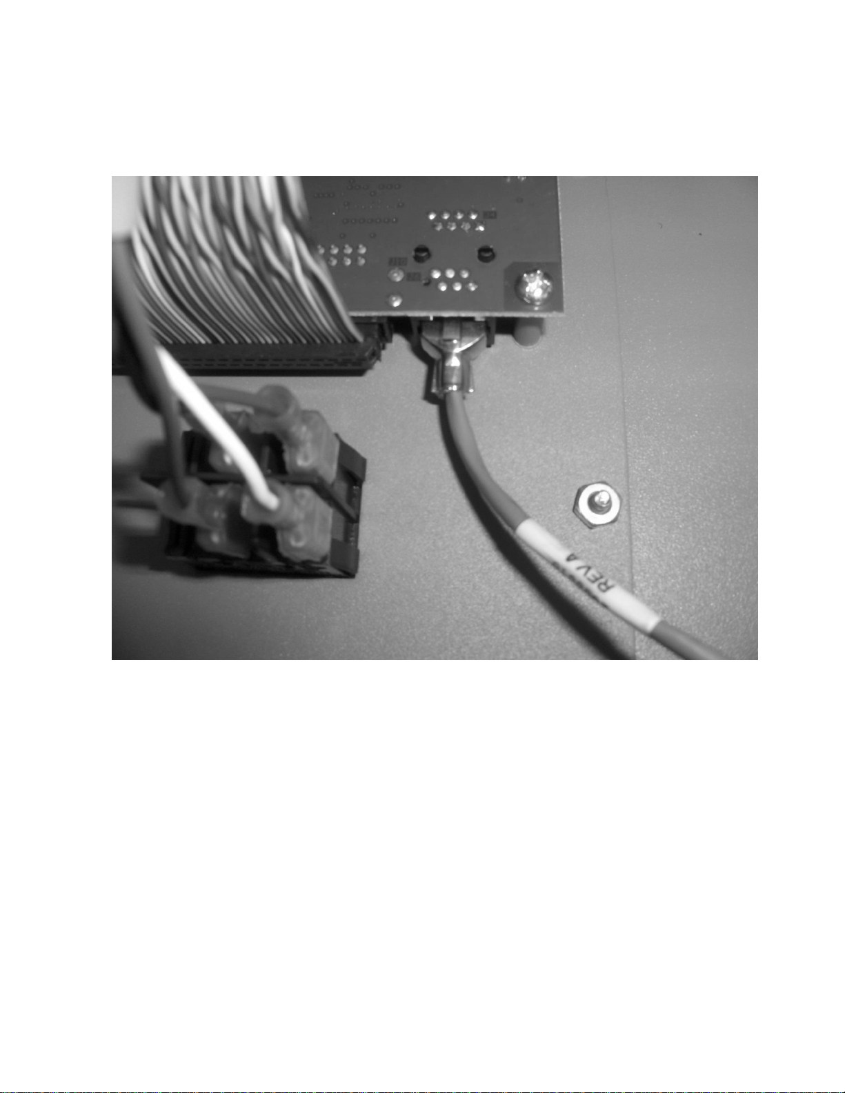
6 Connect RJ-45 end of the cable in step 6 into the port on the lower end of the processor
board. The processor board is mounted on the door of the control cabinet.
11 | Links XPS for MHTC
Figure 8: RJ45 Connection to Processor Board
Page 15
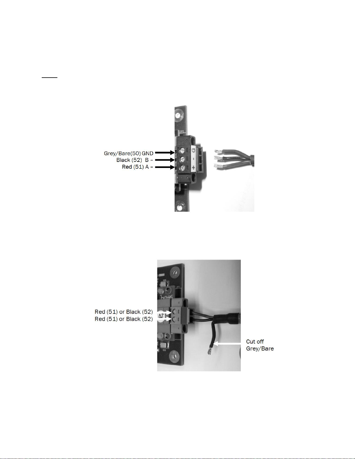
7 Locate the remaining short 3-wire cable. Connect this cable to the Building Automation
System end of the XPS module as shown in Figure 8 (N2, BACnet MSTP) or Figure 9 (LonWorks).
Lonworks is not polarity sensitive.
Note: BACnet IP packages do not require this step since they use the ethernet port on the XPS
module for communications.
Figure 9: Building Automation Connections (Johnson N2/ BACnet MS/TP)
Figure 10: Building Automation Connections (Lonworks)
Links XPS for MHTC | 12
Page 16
Wiring diagrams are provided below for reference.
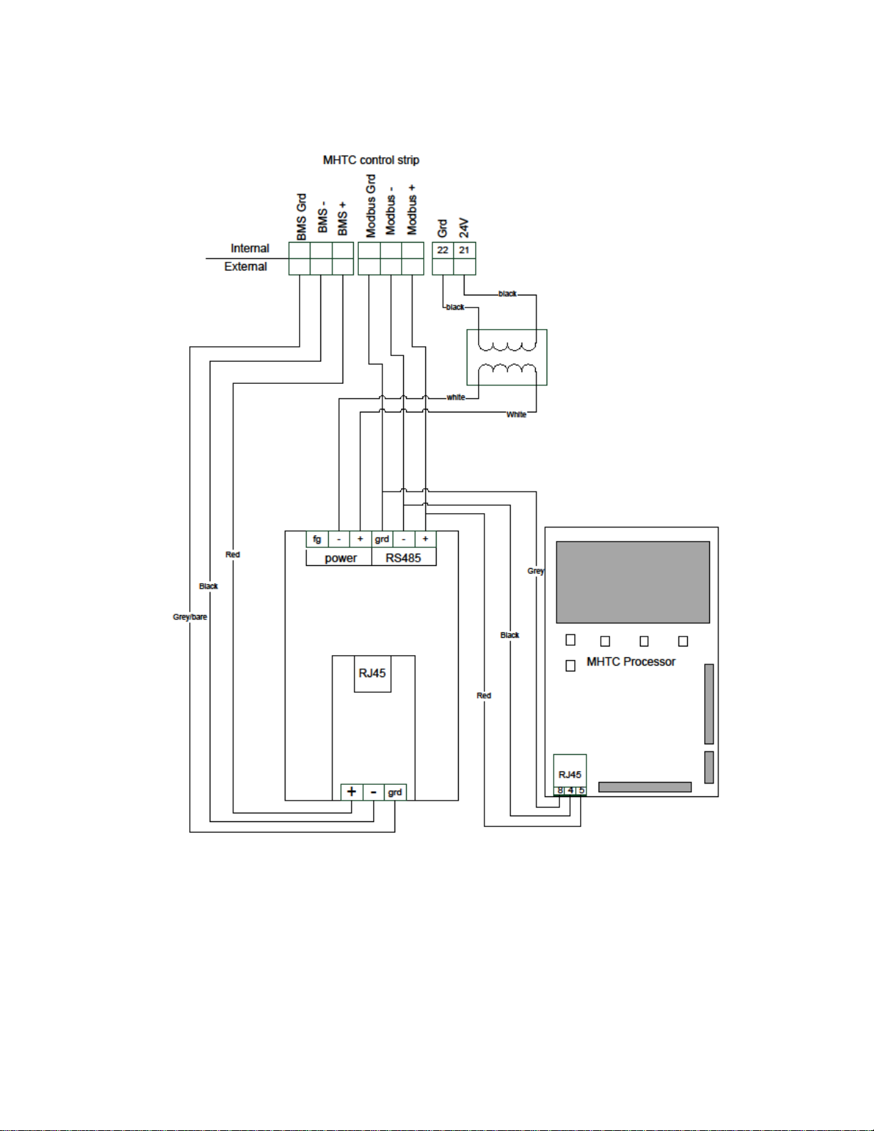
13 | Links XPS for MHTC
Figure 11: Links XPS for MHTC with BACnet MSTP or N2
Page 17
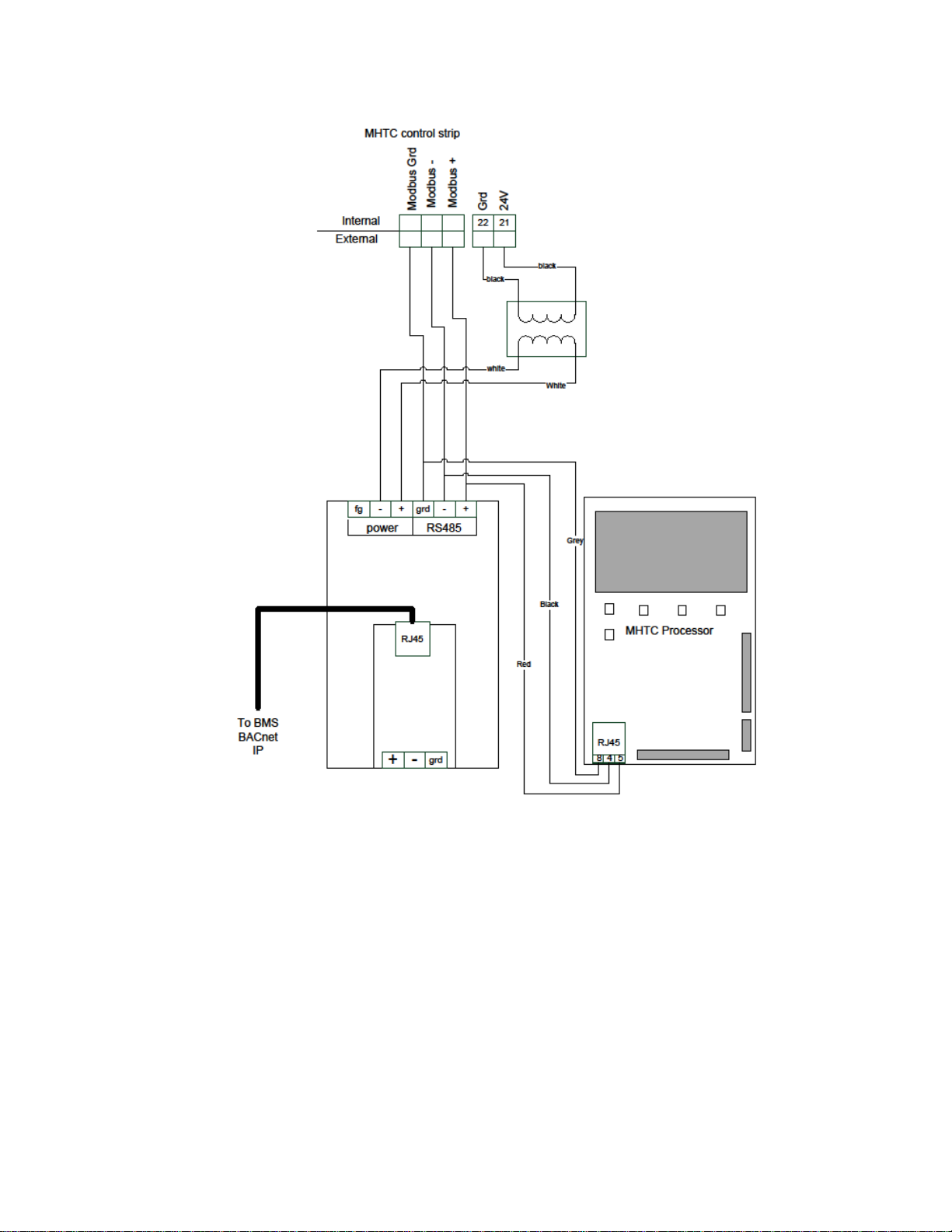
Figure 12: Links XPS for MHTC with BACnet IP only
Links XPS for MHTC | 14
Page 18
15 | Links XPS for MHTC
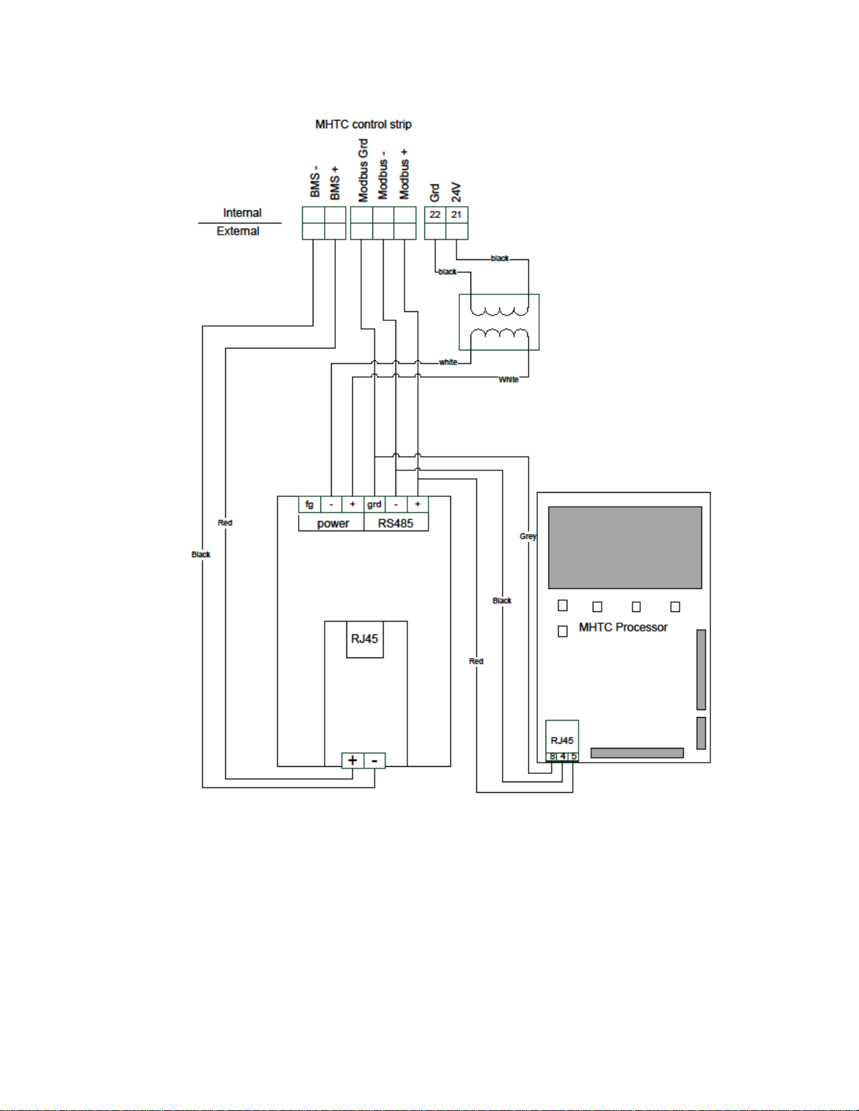
Figure 13: Links XPS for MHTC with LonWorks
Page 19

Configuring the Humidifiers
The PCB processor board will need to be configured to work with the Links XPS modules.
Additionally, Nortec Links XPS can connect to a maximum of 8 units from a single Links XPS
gateway. If slave units are being used it is necessary to set the address of each slave module.
The address should be the number the nit will have on the networked chain.
Links XPS can be used for control, monitoring, or both. To set the control mode on the
humidifier, on the humidifier refer to the procedure on page 52 of the MH2 Installation and
Operation Manual to enter the controls menu.
If you would like to control the humidifier directly by signal writing values over the Links XPS
package set the Signal Source to Modbus. The humidifier will now look for values to be written
to the humidifier.
If you would like to use an analog control signal (from a wall stat or building automation system)
leave Signal Source setting to Analog and then set Hum. Control and Controlsign. to match the
type of controls being used. Ensure that controls are physically wired to terminals 3 and 4 on
the DIN rail terminal strip.
To set the humidifier to recognize the Links XPS package:
1 On the humidifier keypad, Press the menu button on the keypad and scroll to the User menu
using the arrow keys. Press Set to enter the User menu.
2 When prompted for a password, use the arrow keys to enter 8808 and press Set to confirm.
3 Scroll to the Modbus menu and press Set to enter the menu.
4 Set the Parity to None1.
5 Set the Modbus address of the lead unit to 1. Repeat this step for any slave humidifiers,
taking care to assign each slave unit a unique and sequential number. For example if the
lead is 1, subsequent units should be 2, 3, 4, etc.
Note: Ensure that no units share the same Modbus address.
6 Place the appropriate Unit Identifier label on each humidifier. These laps should match the
Modbus address for that humidifier and should be placed in a visible location.
7 Connect the slave humidifiers (if applicable) to the Nortec Links Module. A twisted pair cable
should be used so that the Net (+) terminal on the Links module should connect to the Net
(+) terminal on the slave unit (NHTC). The Net (–) terminal on the module should be
connected to the Net (–) terminal on the slave unit. Refer to the Links XPS wiring diagram for
more information.
Links XPS for MHTC | 16
Page 20
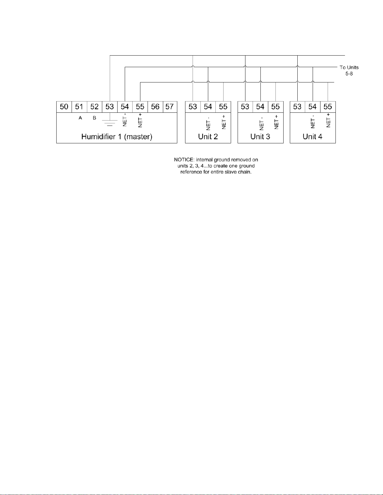
8 Ensure shield wiring matches the following pattern if distances between humidifiers is
significant (2200 ft):
Figure 14: Multiple Slave Humidifiers
17 | Links XPS for MHTC
Page 21

Protocol
Signal
Type
Polarity
Recommended
Cable
Maximum
Recommended Distance
from Nortec Module
A
B
BACnet MS/TP
EIA-485,
2-wire
Net +
Net -
18-24 AWG
Shielded, Twisted
Pair
120 Impedance
2300 ft at 9.6 kbps
2000 ft at 38.4 kbps
Johnson N2
LonWorks
FTT-10, 2-
wire
Tx Rx
18-24 AWG
Twisted Pair
120 Impedance
Should not exceed 50 ft.
BACnet/IP
LAN
standard
N/A
N/A
CAT.5E cable with
RJ-45 termination
Depends on cable
manufacturer
Wiring
BACnet MS/TP, Johnson N2, and LonWorks
Links XPS is pre-installed and factory wired. Connections must be made between the master
humidifier and the BMS, and the master humidifier and any slaves that may be present.
Up to 8 units (1 master, 7 slaves) may be connected to a BMS through a single gateway in the
master unit. The units are daisy chained via the Links XPS terminal strip. The wire shield
should only be connected at one end per pair of units when “daisy chaining”.
Table 2 refers to the recommended wire types and maximum recommended lengths from the
Nortec Links XPS module to the Building Management system. Communication between the
humidifiers and Nortec Links XPS will occur via a EIA-485 signal type. Nortec recommends using
a 18-24 AWG shielded, 120 twisted pair wire between the lead humidifier and each of the
slave humidifiers. Total cable length runs between the Nortec Links XPS module and the
furthest slave humidifier should not exceed 2,000 feet. Signal boosters or repeaters may be
necessary for longer wire runs or where electrical noise interference is prevalent.
Table 2: Recommended Wire Types and Lengths
Links XPS for MHTC | 18
Page 22

BACnet/IP
A standard CAT-5E cable with an RJ-45 (Ethernet) jack is to be connected to the Ethernet port
on the Links XPS module. Refer to wiring diagrams in this manual.
Cable Shielding
The cable’s shield should be connected to the shield terminal at the BMS system only, and not
the Links XPS module.
As well the cable shield should be connected at the lead unit only and not at subsequent units.
For long chains the shield would appear as:
Unit 2 to Master - Shield connected at master only.
Unit 3 to Unit 2 - Shield connected at unit 2 only.
Unit 4 to Unit 3 - Shield connected at unit 3 only.
And so forth.
19 | Links XPS for MHTC
Page 23

Gateway Configuration
Protocol configuration is completed at the factory, prior to final testing. If configuration
information was supplied at the time of order, the units will be configured for plug-and-play
installation with no further configuration required. If this information was unavailable, it will be
necessary to configure the addressing parameters.
BACnet IP systems will require a static IP address to communicate on the network, and may
require a device instance and MAC address
BACnet MS/TP and Johnson N2 systems require both a device instance, MAC address and
a baud rate to be set.
LonWorks systems automatically detect network address parameters and do not require
configuration.
Changing BACnet Device Instance and BACnet MAC Address
The initial step is to determine if both BACnet Device Instance and MAC address can be the
same value. If not, skip to Part B. If yes, continue with Part A using solely the small dipswitches.
Part A: Device Instance and MAC address same value
The device instance and BACnet MAC address can be easily changed to the same value using
the dip switches (SW3 Bank 1 through 8) highlighted on figure 10. Notice these are the smaller
dipswitches, not the larger ones.
Figure 15: Dip Switches for BACnet Address Changes
Links XPS for MHTC | 20
Page 24

Figure 16: Respective Address and Baudrate Dipswitches
These switches allow you to set a binary value for the device instance between 1 and 127
inclusively. To set the device instance to a value outside of this range, skip to PART B.
21 | Links XPS for MHTC
Page 25

Switch
A8
A7
A6
A5
A4
A3
A2
A1
Setting
Off
On
Off
Off
On
On
On
Off
Binary 0 1 0 0 1 1 1 0
Exponential Meaning
27 x 0
26 x 1
25 x 0
24 x 0
23 x 1
22 x 1
21 x 1
20 x 0
Simplified Meaning
128 x 0
64 x 1
32 x 0
16 x 0
8 x 1
4 x 1
2 x 1
1 x 0
Numerical Meaning
0
64 0 0 8 4 2 0
Result
64 + 8 + 4 + 2 = 78
Value
A8
A7
A6
A5
A4
A3
A2
A1
0 (cannot be used)
Off
Off
Off
Off
Off
Off
Off
Off
1
Off
Off
Off
Off
Off
Off
Off
On
10
Off
Off
Off
Off
On
Off
On
Off
25
Off
Off
Off
On
On
Off
Off
On
40
Off
Off
On
Off
On
Off
Off
Off
50
Off
Off
On
On
Off
Off
On
Off
75
Off
On
Off
Off
On
Off
On
On
78
Off
On
Off
Off
On
On
On
Off
100
Off
On
On
Off
Off
Off
On
Off
125
Off
On
On
On
On
On
Off
On
127
Off
On
On
On
On
On
On
On
The methodology for converting numbers to binary is presented in the example below. In this
example, a value of 78 is converted to binary and set as the device instance:
Table 3: Converting Numbers to Binary
When adjusting switches be sure to adjust only the switches highlighted in the box in Table 3
above. Also, switches may be presented in reverse order (compared with the table below) on
the physical hardware itself. Take care when adjusting switches to ensure the settings are
entered as intended. Common settings are tabulated below:
Table 4: Common Settings
Links XPS for MHTC | 22
Page 26

Setting
B4
B3
B2
B1
110
Off
Off
Off
On
300
Off
Off
On
Off
600
Off
Off
On
On
1200
Off
On
Off
Off
2400
Off
On
Off
On
4800
Off
On
On
Off
9600
Off
On
On
On
19200
On
Off
Off
Off
20833
On
Off
Off
On
28800
On
Off
On
Off
38400
On
Off
On
On
57600
On
On
Off
Off
76800
On
On
Off
On
115200
On
On
On
Off
After an address change has been made, the Links XPS module must be power cycled for the
change to take effect. The module may take up to 60 seconds to restart after a power cycle.
Changing Baud Rate (BACnet MSTP, Johnson N2, LonWorks)
The baud rate for communications must be changed through dipswitches (SW4 Bank, 1 through
4). Refer to figure 16 for location of the dipswitch.
By adjusting the settings according to the table 5, the baud rate can be changed. The Baud rate
must be set to exactly the same baud rate as your Building Management System.
Communication performance varies with building automation system manufacturer and some
experimentation with other baud rates may be required to obtain the best performance.
Table 5: Common Settings
After an address change has been made, the Links XPS module must be power cycled for the
change to take effect. The module may take up to 60 seconds to restart after a power cycle.
23 | Links XPS for MHTC
Page 27

Figure 17: Retrieval of Protocessor Software Tool
Part B: Device Instance and MAC address different values
First, ensure the addressing dipswitches (mentioned in Part A) for Bank SW3 are all set to OFF
or are set to 128 or higher. Also ensure your Baud rate dipswitches are properly set (Bank SW4)
see previous chapter for details.
The device instance and BACnet MAC address can now be changed to be different values using
a free software tool. To obtain this program, visit the link below, and then download and install
the latest version of the “Utility Software” (8 MB file called Install.zip).
www.protocessor.com/tech-support/utilities-and-design-documents.php
Links XPS for MHTC | 24
Page 28

Once the free tool has been downloaded to a computer (preferably a laptop), extract and install
it. NOTE: you will require administrative privileges on the computer to perform the installation,
contact your network administrator for assistance. Once completed, use the following steps to
perform the addressing changes:
To change the Device Instance and MAC Address:
1. Connect the computer to the ethernet port of the Links XPS module. (you will need a
Category 5 or better cable (CAT5)
2. Power up the Links XPS module. During the boot process 8 multi-colored LED’s may
illuminate.
3. On the computer navigate to Start > Programs > Fieldserver Utilities > Remote User
Interface.
4. A blue window will launch, running a program named “Remote User Interface”. Any Links
XPS models detected will be listed as “Fieldservers discovered on the network”. If no
modules are detected you will receive the following screen:
Figure 18: Screen for No Modules Detected
This error is most likely due to the network configuration of the computer. By default, the Links
XPS modules ship with an address of 192.168.10.11. If your computer is not already on the
192.168.10.0 domain, you will need to set your computer IP address to a unique address within
this range. You may need to turn off or disable any wireless connections before beginning to
avoid conflicts. For Windows systems, this setting is located in:
25 | Links XPS for MHTC
Page 29

Windows XP: Start > Control Panel > Network Connections
Windows Vista, 7: Start > Control Panel > Network and Sharing Center
Windows 8.1: Desktop Start (right click) > Control Panel > Network and Sharing Center
Select your Ethernet or Local Area Connection, right click, and select Properties. In the Window
that pops up, locate the Internet Protocol (TCP/IPv4) and click it to highlight it. Next click the
Properties button. Take note of your existing settings as will need to re-enter them later, then
enter the settings below: ( IP= 192.168.10.99, subnet=255.255.255.0,
gateway=192.168.10.1)
Figure 19: Internet Protocol Properties Screen
Click OK on both of the open windows, and your connection will reset with the new settings.
After about 30 seconds, it will be ready to use.
Links XPS for MHTC | 26
Page 30

When the Remote User Interface successfully detects a Links Module you should see a screen
similar to below:
Figure 20: Remote User Interface Successfully Detects Links XPS Module
When the device has been detected and appears in the list, press the number listed to the left
of it (usually 1) to select it. This will bring up a prompt to reset the time. Type Y to continue, you
will next be greeted with the main menu.
27 | Links XPS for MHTC
Figure 21: Main Menu Screen
Page 31

Figure 22: Retrieving the Configuration File
Figure 23: Retrieval Complete
From the Main Menu, type U for Upload. You will be prompted with the following screen:
Type U once more to initiate retrieval of the configuration file.
Links XPS for MHTC | 28
Page 32

Figure 24: Changing The MAC Address
Once transfer is complete you may type N which automatically opens the retrieved file into
Notepad . Note: file is named config.csv and is located in configuration File Folder
(Start>Programs>Fieldserver Utitlities>Configuration File Folder). Do not open the file in
Microsoft Excel, you may accidentally corrupt it.
Once the configuration file is open in Notepad, you will have to change addressing at two
locations.
Modifying MAC address:
Use the Ctrl and F key to bring up the find command. Type in the find command, the words
“common information”. The following screen should appear:
Below the words Common Information, you will see the number 11, this is the default MAC
address, change as desired. Note: MAC address must be between 1-254 Inclusive.
29 | Links XPS for MHTC
Page 33

Figure 25: Changing the Device Instance
Modifying Device Instance:
Once again, use the Ctrl and F key to bring up the find command. Type in the find command, the
words “server side nodes”. The following screen should appear:
Below the words Server Side Nodes, you will see the number 11, this is the default Device
Instance, change as desired. Note: Device Instance must be between 1-16’777’215 Inclusive.
Once complete, save the notepad file and close it. Return to the Remote User Interface program
and press Esc until you return to the Main Menu
Links XPS for MHTC | 30
Page 34

Figure 26: Returning the Configuration File Back to Links XPS module
Type D for download, you will be prompted with the following screen:
Type D once more to return the configuration file back to the Links XPS module. Once download
is completed, you can type the “Esc” key until you return to the main menu. Next select ! (Hold
the Shift key and press the 1 key simultaneously) to restart the module causing the changes to
take effect.
31 | Links XPS for MHTC
Page 35

Figure 27: Restarting the XPS Module
Figure 28: Awaiting Reboot of the XPS Module
The following screen will appear:
Links XPS for MHTC | 32
Page 36

Press the Esc key to return to the discovery screen. The screen will remain in discovery mode
until the Links XPS module has successfully completed the reboot. Once reboot complete, you
may disconnect your laptop from the Links XPS module and verify that your BMS can discover
the humidifier.
Changing the IP Address (BACnet IP)
The IP address of the module can also be configured for BACnet IP networks. To configure the
IP address, a freely downloadable configuration program is required as mentioned in the
previous chapter.
To change the IP Address:
1. Connect the computer to the ethernet port of the Links XPS module.
2. Power up the module. During the boot process 8 multi-colored LED’s will illuminate and
remain steady. The module is ready when most of these LED’s have turned off.
3. On the computer navigate to Start > Programs > Fieldserver Utilities > Remote User
Interface.
4. A blue window will launch, any Links XPS models detected will be listed as “Fieldservers
discovered on the network”. If no modules are detected you will receive the following
screen:
Figure 29: Screen for No Modules Detected
This error is most likely due to the network configuration of the computer. By default, the Links
XPS modules ship with an address of 192.168.10.11. If your computer is not already on the
33 | Links XPS for MHTC
Page 37

192.168.10.0 domain, you will need to set your computer IP address to a unique address within
this range. You may need to turn off or disable any wireless connections before beginning to
avoid conflicts. For Windows systems, this setting is located in:
Windows XP: Start > Control Panel > Network Connections
Windows Vista, 7: Start > Control Panel > Network and Sharing Center
Windows 8.1: Desktop Start (right click) > Control Panel > Network and Sharing Center
Select your Ethernet or Local Area Connection, right click, and select Properties. In the Window
that pops up, locate the Internet Protocol (TCP/IPv4) and click it to highlight it. Next click the
Properties button. Take note of your existing settings as will need to renter them later, then
enter the settings below: ( IP= 192.168.10.99, subnet=255.255.255.0,
gateway=192.168.10.1)
Figure 30: Internet Protocol Properties Screen
Click OK on both of the open windows, and your connection will reset with the new settings.
After about 30 seconds, it will be ready to use.
Links XPS for MHTC | 34
Page 38

When Remote User Interface successfully detects a Links Module you should see a screen
similar to below:
Figure 31: XPS Module Detected
35 | Links XPS for MHTC
Page 39

When the device has been detected and appears in the list, press the number listed to the left
of it (usually 1) to select it. This will bring up the main menu.
Figure 32: Main Menu
Press I to change the IP address. This will bring up the IP address settings.
Figure 33: Changing IP Address
Links XPS for MHTC | 36
Page 40

To edit the IP address, press the 1 key, type in the desired address, and then press Enter once.
Repeat the process for the Netmask (selection 2), and the Gateway (selection 3). For most
reliable performance, activating DHCP is not recommended.
When the IP address change is completed press Esc to return to the main menu. Next select !
(Hold the Shift key and press the 1 key simultaneously) to restart the module causing the
changes to take effect.
Figure 34: Restarting XPS Module
Press any key to exit this screen. The module will reboot and may take up to 1 minute to fully
restart. If you changed the IP address significantly, the module may no longer be reachable with
your IP address settings resulting in the same error described in step 4
To rectify this, change your IP address to a unique address in the same domain as the one you
entered for the Fieldserver by following the instructions in step 4. Once communication has
been re-established, you can quickly verify the change was successful by noting the address
displayed under “Fieldservers discovered on the network”.
When completed, be sure to restore your existing IP address settings for your computer
following the instructions in step 4 and substituting the settings you had noted originally.
37 | Links XPS for MHTC
Page 41

Network Integration
LonWorks.xif file
To facilitate the integration of a LonWorks unit within a network, it may be desirable to obtain an
External Interface File (XIF). Files of type .xif are used to convey the resources, specific objects
and data types which a LonWorks device possesses. The .xif file allows a network integrator to
simulate the presence of a networked humidifier even if it is not yet physically connected to the
network. In fact, if the integrator has the .xif files of all network devices, a complete system
could be simulated and configured off-line. Once the configuration is done, the integrator's
software tool can be connected to the actual system and the configuration information can be
downloaded.
Retrieving XIF File Instructions
The XIF file can be retrieved directly from the Links XPS Module. A Windows based laptop and
an Ethernet cable are required for this process.
This process requires the “Remote User Interface” tool from Protocessor described earlier in
this manual. It is available by visiting www.protocessor.com/tech-support/utilities-and-design-
documents.php and download and install the “Utility” software.
Once this software has been installed, follow the following procedure:
1. Locate desired MASTER humidifier that contains the Links package. Ensure unit is powered
on and remove the panel on the RIGHT side of the humidifier. Locate the Links package
inside of the unit.
2. For LINKS XPS packages (gateway device on its own), connect the CAT5 cable directly into
the Ethernet port on the gateway.
3. Connect other end of CAT5 cable to the Ethernet port on the laptop.
4. Run the “Remote User Interface” utility by double clicking the shortcut on your desktop (or
Start>Programs>Fieldserver Utilities>Remote User Interface)
5. The program should automatically recognize connected humidifier and bring you to the
“Main Menu”. If it does not, contact Nortec Technical Services at the number on the back
cover of this manual.
6. Type “u” for upload.
7. Type “o” for other. (A warning will appear, press any key to continue.)
8. Type “r” for remote.
9. Enter “fserver.xif”’ and hit the ‘enter’ key.
10. Type “u” to initiate upload from the gateway to the laptop.
Links XPS for MHTC | 38
Page 42

11. The .xif file will be saved in the folder “Configuration File Folder” located at
Start>Programs>Fieldserver Utilities>Configuration File Folder.
12. Type ‘q’ twice to exit out of the program
13. Locate file in Configuration File Folder and change name to corresponding humidifier, (ex,
“fserverH1.xif” for Humidifier 1)
14. Repeat this procedure for all Master humidifiers changing the name of the .xif once saved
to correspond with the tag of the appropriate humidifier.
39 | Links XPS for MHTC
Page 43

In the variable name, “_x” denotes the humidifier number. If there is only one humidifier, all variable
names will end in “_1”. If two units are networked together, see Figure 4, the second unit’s variable names
will end in “_2”. For 3 networked units, “_3” and so on. If unsure of the unit number, each unit will have a
label, in the electrical compartment close to the terminal strip, indicating the device instance of each
humidifier.
BACnet Pics and Bibs
The Protocol Implementation Conformance Statement or “PICS” describes the BACnet
capabilities of a particular BACnet implementation. It is a written document, created by the
manufacturer of a device, which identifies the particular options specified by BACnet that are
implemented in the device.
BACnet Interoperability Building Blocks (BIBBs) describe a list of services a BACnet device
provides. The main areas that the building blocks are concerned with include: data sharing,
trends, schedules, device and system management. BIBBs help specify the interoperability
capabilities of a BACnet device. Please contact the factory to obtain a PICS statement or BIBBs
profile.
Variable Definition
Nortec Links XPS is capable of communicating a variety of variables for each unit that is
connected to it. For a variable listing and definition refer to Table 6. Network variable addresses
for the humidifiers may be seen in Table 7 to Table 14.
Links XPS for MHTC | 40
Page 44

Variable Namee
R = Read
W = Write
Description
nviCapLimit_x
W
Analog Value
Sets humidifier capacity limit (50-100%)
Example: 500 = 50%, 1000=100%
nvoCapLimit_x
R
Analog Value
Read Manual capacity (50-100%)
Example: 500 = 50%, 1000=100%
nviRHDem1_x
W
Analog Value
Writes channel 1 demand or %RH. Allows BAS control of output.
(0 - 100%). Unit must be configured to accept network demand.
Example: 500 = 50%, 1000=100%
nvoRHDem1_x
R
Analog Value
Reads channel 1 demand or %RH. Allows BAS control of output.
(0 - 100%). Unit must be configured to accept network demand.
Example: 500 = 50%, 1000=100%
nviSet1_x
W
Analog Value
Writes setpoint when humidifier is operating on
sensor/transducer controls. Acceptable values are 10 - 90 %.
Example: 500 = 50%, 900=90%
nvoSet1_x
R
Analog Value
Reads setpoint when humidifier is operating on
sensor/transducer controls. Acceptable values are 10 - 90 %.
Example: 500 = 50%, 900=90%
nviDisable_x
W
Binary Value
Allows for remote disable of humidifier.
0 = Run
1 = Disable
nvoDisable_x
R
Binary Value
Checks remote disable status.
0 = Run
1 = Disable
nviNetSensor_x
W
Binary Value
Configures unit to look for either hardwired controls or control
value written from building automation system.
0 = Hard wired controls
1 = Network controls
nvoNetSensor_x
R
Binary Value
Checks current control source.
0 = Hard Wired
1 = Network
nvoFault_x
R
Binary Value
Reads fault status.
0 = Normal operation
1 = Unit Fault
nvoSecurity_x
R
Binary Value
Checks status of security loop (on/off controls wired in series
between terminals 1 and 2 on the low voltage terminal strip).
Humidifier will only operate if loop is closed.
0 = Open
1 = Closed
nvoService_x
R
Binary Value
Checks service light status.
0 = Normal operation
1 = Service required, check humidifier display for information.
nviHum_Control_x
W
Analog Value
Change control type that humidifier is accepting.
Warning: Check physical control type before modifying.
0 = Demand signal
1 = On/Off signal
2 = Transducer (sensed %RH), humidifier uses proportional
algorithm
3 = Transducer (sensed %RH), humidifier uses proportionalintegral algorithm
Table 6: Variable Definitions
41 | Links XPS for MHTC
Page 45

Variable Name
R=Read
W=Write
Description
nvoHum_Control_x
R
Analog Value
Read control mode status.
0 = Demand Signal
1 = On/Off signal
2 = Sensed RH signal, humidifier used proportional algorithm
3 = Sensed RH signal, humidifier uses proportional-integral
algorithm
nvoServTime_x
R
Analog Value
Indicates operation hours.
nvoPumpRunHr_x
R
Analog Value
Indicates total run hours of pump since manufacture.
nvoUVRunHr_x
R
Analog Value
Indicates total run hours of UV since last reset.
nvoStage1Dem_x
R
Binary Value
Indicates if stage 1 is actively humidifying.
1 = On
2 = Off
nvoStage2Dem_x
R
Binary Value
Indicates if stage 2 is actively humidifying.
1 = On
2 = Off
nvoStage3Dem_x
R
Binary Value
Indicates if stage 3 is actively humidifying.
1 = On
2 = Off
nvoWarning_x
R
Binary Value
Indicates that a warning is present on the humidifier. Check
humidifier display for warning information.
1 = Warning
0 = No Warning
nvoCleaning_x
R
Binary Value
Indicates that a cleaning cycle is active.
1 = Clean Cycle Active
0 = Inactive
nvoTankDrain_x
R
Binary Value
Indicates that tank drain is active.
1 = Drain Cycle Active
0 = Inactive
nvoTankLevel_x
R
Binary Value
Indicates Tank Water Level.
1 = Full Water
0 = Below Full
Table 6: Variable Definitions - CONTINUED
Links XPS for MHTC | 42
Page 46

Unit #1
BACnet
Lonworks
N2
Variable Name
Type
Instance
SNVT
SNVT #
NV Index
Type
Instance
nvoServTime_1
AV 1 SNVT_lev_count_f
55
1
Ana_Output
1
nvoPumpRunHr_1
AV 2 SNVT_lev_count_f
55
2
Ana_Output
2
nvoUVRunHr_1
AV 3 SNVT_lev_count_f
55
3
Ana_Output
3
nvoSet1_1
AV 4 SNVT_lev_count_f
55
4
Ana_Output
4
nvoHum_Control_1
AV 5 SNVT_lev_count_f
55
5
Ana_Output
5
nvoCapLimit_1
AV 6 SNVT_lev_count_f
55
6
Ana_Output
6
nvoRHDem1_1
AV 7 SNVT_lev_count_f
55
7
Ana_Output
7
nviSet1_1
AV 8 SNVT_lev_count_f
55
8
Ana_Output
8
nviRHDem1_1
AV 9 SNVT_lev_count_f
55
9
Ana_Output
9
nviHum_Control_1
AV
10
SNVT_lev_count_f
55
10
Ana_Output
10
nviCapLimit_1
AV
11
SNVT_lev_count_f
55
11
Ana_Output
11
nvoNetSensor_1
BV 1 SNVT_switch
95
12
Dig_Output
1
nvoDisable_1
BV 2 SNVT_switch
95
13
Dig_Output
2
nvoStage1Dem_1
BV 3 SNVT_switch
95
14
Dig_Output
3
nvoStage2Dem_1
BV 4 SNVT_switch
95
15
Dig_Output
4
nvoStage3Dem_1
BV 5 SNVT_switch
95
16
Dig_Output
5
nvoWarning_1
BV 6 SNVT_switch
95
17
Dig_Output
6
nvoService_1
BV 7 SNVT_switch
95
18
Dig_Output
7
nvoFault_1
BV 8 SNVT_switch
95
19
Dig_Output
8
nvoCleaning_1
BV 9 SNVT_switch
95
20
Dig_Output
9
nvoTankDrain_1
BV
10
SNVT_switch
95
21
Dig_Output
10
nvoSecurity_1
BV
11
SNVT_switch
95
22
Dig_Output
11
nvoTankLevel_1
BV
12
SNVT_switch
95
23
Dig_Output
12
nviNetSensor_1
BV
13
SNVT_switch
95
24
Dig_Output
13
nviDisable_1
BV
14
SNVT_switch
95
25
Dig_Output
14
Table 7: Humidifier Variable Addresses – Unit #1
MHTC Links XPS Variable Listing and Default Settings
Default BACnet/IP Address: 192.168.10.11; Subnet: 255.255.255.0
Default BACnet/MSTP: MAC Address = 11, Device Instance = 11
Default Johnson N2 Address: 11
43 | Links XPS for MHTC
Page 47

Unit #2
BACnet
Lonworks
N2
Variable Name
Type
Instance
SNVT
SNVT #
NV Index
Type
Instance
nvoServTime_2
AV
12
SNVT_lev_count_f
55
26
Ana_Output
12
nvoPumpRunHr_2
AV
13
SNVT_lev_count_f
55
27
Ana_Output
13
nvoUVRunHr_2
AV
14
SNVT_lev_count_f
55
28
Ana_Output
14
nvoSet1_2
AV
15
SNVT_lev_count_f
55
29
Ana_Output
15
nvoHum_Control_2
AV
16
SNVT_lev_count_f
55
30
Ana_Output
16
nvoCapLimit_2
AV
17
SNVT_lev_count_f
55
31
Ana_Output
17
nvoRHDem1_2
AV
18
SNVT_lev_count_f
55
32
Ana_Output
18
nviSet1_2
AV
19
SNVT_lev_count_f
55
33
Ana_Output
19
nviRHDem1_2
AV
20
SNVT_lev_count_f
55
34
Ana_Output
20
nviHum_Control_2
AV
21
SNVT_lev_count_f
55
35
Ana_Output
21
nviCapLimit_2
AV
22
SNVT_lev_count_f
55
36
Ana_Output
22
nvoNetSensor_2
BV
15
SNVT_switch
95
37
Dig_Output
15
nvoDisable_2
BV
16
SNVT_switch
95
38
Dig_Output
16
nvoStage1Dem_2
BV
17
SNVT_switch
95
39
Dig_Output
17
nvoStage2Dem_2
BV
18
SNVT_switch
95
40
Dig_Output
18
nvoStage3Dem_2
BV
19
SNVT_switch
95
41
Dig_Output
19
nvoWarning_2
BV
20
SNVT_switch
95
42
Dig_Output
20
nvoService_2
BV
21
SNVT_switch
95
43
Dig_Output
21
nvoFault_2
BV
22
SNVT_switch
95
44
Dig_Output
22
nvoCleaning_2
BV
23
SNVT_switch
95
45
Dig_Output
23
nvoTankDrain_2
BV
24
SNVT_switch
95
46
Dig_Output
24
nvoSecurity_2
BV
25
SNVT_switch
95
47
Dig_Output
25
nvoTankLevel_2
BV
26
SNVT_switch
95
48
Dig_Output
26
nviNetSensor_2
BV
27
SNVT_switch
95
49
Dig_Output
27
nviDisable_2
BV
28
SNVT_switch
95
50
Dig_Output
28
Table 8: Humidifier Variable Addresses - Unit #2
Links XPS for MHTC | 44
Page 48

Unit #3
BACnet
Lonworks
N2
Variable Name
Type
Instance
SNVT
SNVT #
Element
Type
Instance
nvoServTime_3
AV
23
SNVT_lev_count_f
55
51
Ana_Output
23
nvoPumpRunHr_3
AV
24
SNVT_lev_count_f
55
52
Ana_Output
24
nvoUVRunHr_3
AV
25
SNVT_lev_count_f
55
53
Ana_Output
25
nvoSet1_3
AV
26
SNVT_lev_count_f
55
54
Ana_Output
26
nvoHum_Control_3
AV
27
SNVT_lev_count_f
55
55
Ana_Output
27
nvoCapLimit_3
AV
28
SNVT_lev_count_f
55
56
Ana_Output
28
nvoRHDem1_3
AV
29
SNVT_lev_count_f
55
57
Ana_Output
29
nviSet1_3
AV
30
SNVT_lev_count_f
55
58
Ana_Output
30
nviRHDem1_3
AV
31
SNVT_lev_count_f
55
59
Ana_Output
31
nviHum_Control_3
AV
32
SNVT_lev_count_f
55
60
Ana_Output
32
nviCapLimit_3
AV
33
SNVT_lev_count_f
55
61
Ana_Output
33
nvoNetSensor_3
BV
29
SNVT_switch
95
62
Dig_Output
29
nvoDisable_3
BV
30
SNVT_switch
95
63
Dig_Output
30
nvoStage1Dem_3
BV
31
SNVT_switch
95
64
Dig_Output
31
nvoStage2Dem_3
BV
32
SNVT_switch
95
65
Dig_Output
32
nvoStage3Dem_3
BV
33
SNVT_switch
95
66
Dig_Output
33
nvoWarning_3
BV
34
SNVT_switch
95
67
Dig_Output
34
nvoService_3
BV
35
SNVT_switch
95
68
Dig_Output
35
nvoFault_3
BV
36
SNVT_switch
95
69
Dig_Output
36
nvoCleaning_3
BV
37
SNVT_switch
95
70
Dig_Output
37
nvoTankDrain_3
BV
38
SNVT_switch
95
71
Dig_Output
38
nvoSecurity_3
BV
39
SNVT_switch
95
72
Dig_Output
39
nvoTankLevel_3
BV
40
SNVT_switch
95
73
Dig_Output
40
nviNetSensor_3
BV
41
SNVT_switch
95
74
Dig_Output
41
nviDisable_3
BV
42
SNVT_switch
95
75
Dig_Output
42
Table 9: Humidifier Variable Addresses - Unit #3
45 | Links XPS for MHTC
Page 49

Unit #4
BACnet
Lonworks
N2
Variable Name
Type
Instance
SNVT
SNVT #
Element
Type
Instance
nvoServTime_4
AV
34
SNVT_lev_count_f
55
76
Ana_Output
34
nvoPumpRunHr_4
AV
35
SNVT_lev_count_f
55
77
Ana_Output
35
nvoUVRunHr_4
AV
36
SNVT_lev_count_f
55
78
Ana_Output
36
nvoSet1_4
AV
37
SNVT_lev_count_f
55
79
Ana_Output
37
nvoHum_Control_4
AV
38
SNVT_lev_count_f
55
80
Ana_Output
38
nvoCapLimit_4
AV
39
SNVT_lev_count_f
55
81
Ana_Output
39
nvoRHDem1_4
AV
40
SNVT_lev_count_f
55
82
Ana_Output
40
nviSet1_4
AV
41
SNVT_lev_count_f
55
83
Ana_Output
41
nviRHDem1_4
AV
42
SNVT_lev_count_f
55
84
Ana_Output
42
nviHum_Control_4
AV
43
SNVT_lev_count_f
55
85
Ana_Output
43
nviCapLimit_4
AV
44
SNVT_lev_count_f
55
86
Ana_Output
44
nvoNetSensor_4
BV
43
SNVT_switch
95
87
Dig_Output
43
nvoDisable_4
BV
44
SNVT_switch
95
88
Dig_Output
44
nvoStage1Dem_4
BV
45
SNVT_switch
95
89
Dig_Output
45
nvoStage2Dem_4
BV
46
SNVT_switch
95
90
Dig_Output
46
nvoStage3Dem_4
BV
47
SNVT_switch
95
91
Dig_Output
47
nvoWarning_4
BV
48
SNVT_switch
95
92
Dig_Output
48
nvoService_4
BV
49
SNVT_switch
95
93
Dig_Output
49
nvoFault_4
BV
50
SNVT_switch
95
94
Dig_Output
50
nvoCleaning_4
BV
51
SNVT_switch
95
95
Dig_Output
51
nvoTankDrain_4
BV
52
SNVT_switch
95
96
Dig_Output
52
nvoSecurity_4
BV
53
SNVT_switch
95
97
Dig_Output
53
nvoTankLevel_4
BV
54
SNVT_switch
95
98
Dig_Output
54
nviNetSensor_4
BV
55
SNVT_switch
95
99
Dig_Output
55
nviDisable_4
BV
56
SNVT_switch
95
100
Dig_Output
56
Table 10: Humidifier Variable Addresses - Unit #4
Links XPS for MHTC | 46
Page 50

Unit #5
BACnet
Lonworks
N2
Variable Name
Type
Instance
SNVT
SNVT #
Element
Type
Instance
nvoServTime_5
AV
45
SNVT_lev_count_f
55
101
Ana_Output
45
nvoPumpRunHr_5
AV
46
SNVT_lev_count_f
55
102
Ana_Output
46
nvoUVRunHr_5
AV
47
SNVT_lev_count_f
55
103
Ana_Output
47
nvoSet1_5
AV
48
SNVT_lev_count_f
55
104
Ana_Output
48
nvoHum_Control_5
AV
49
SNVT_lev_count_f
55
105
Ana_Output
49
nvoCapLimit_5
AV
50
SNVT_lev_count_f
55
106
Ana_Output
50
nvoRHDem1_5
AV
51
SNVT_lev_count_f
55
107
Ana_Output
51
nviSet1_5
AV
52
SNVT_lev_count_f
55
108
Ana_Output
52
nviRHDem1_5
AV
53
SNVT_lev_count_f
55
109
Ana_Output
53
nviHum_Control_5
AV
54
SNVT_lev_count_f
55
110
Ana_Output
54
nviCapLimit_5
AV
55
SNVT_lev_count_f
55
111
Ana_Output
55
nvoNetSensor_5
BV
57
SNVT_switch
95
112
Dig_Output
57
nvoDisable_5
BV
58
SNVT_switch
95
113
Dig_Output
58
nvoStage1Dem_5
BV
59
SNVT_switch
95
114
Dig_Output
59
nvoStage2Dem_5
BV
60
SNVT_switch
95
115
Dig_Output
60
nvoStage3Dem_5
BV
61
SNVT_switch
95
116
Dig_Output
61
nvoWarning_5
BV
62
SNVT_switch
95
117
Dig_Output
62
nvoService_5
BV
63
SNVT_switch
95
118
Dig_Output
63
nvoFault_5
BV
64
SNVT_switch
95
119
Dig_Output
64
nvoCleaning_5
BV
65
SNVT_switch
95
120
Dig_Output
65
nvoTankDrain_5
BV
66
SNVT_switch
95
121
Dig_Output
66
nvoSecurity_5
BV
67
SNVT_switch
95
122
Dig_Output
67
nvoTankLevel_5
BV
68
SNVT_switch
95
123
Dig_Output
68
nviNetSensor_5
BV
69
SNVT_switch
95
124
Dig_Output
69
nviDisable_5
BV
70
SNVT_switch
95
125
Dig_Output
70
Table 11: Humidifier Variable Addresses - Unit #5
47 | Links XPS for MHTC
Page 51

Unit #6
BACnet
Lonworks
N2
Variable Name
Type
Instance
SNVT
SNVT #
Element
Type
Instance
nvoServTime_6
AV
56
SNVT_lev_count_f
55
126
Ana_Output
56
nvoPumpRunHr_6
AV
57
SNVT_lev_count_f
55
127
Ana_Output
57
nvoUVRunHr_6
AV
58
SNVT_lev_count_f
55
128
Ana_Output
58
nvoSet1_6
AV
59
SNVT_lev_count_f
55
129
Ana_Output
59
nvoHum_Control_6
AV
60
SNVT_lev_count_f
55
130
Ana_Output
60
nvoCapLimit_6
AV
61
SNVT_lev_count_f
55
131
Ana_Output
61
nvoRHDem1_6
AV
62
SNVT_lev_count_f
55
132
Ana_Output
62
nviSet1_6
AV
63
SNVT_lev_count_f
55
133
Ana_Output
63
nviRHDem1_6
AV
64
SNVT_lev_count_f
55
134
Ana_Output
64
nviHum_Control_6
AV
65
SNVT_lev_count_f
55
135
Ana_Output
65
nviCapLimit_6
AV
66
SNVT_lev_count_f
55
136
Ana_Output
66
nvoNetSensor_6
BV
71
SNVT_switch
95
137
Dig_Output
71
nvoDisable_6
BV
72
SNVT_switch
95
138
Dig_Output
72
nvoStage1Dem_6
BV
73
SNVT_switch
95
139
Dig_Output
73
nvoStage2Dem_6
BV
74
SNVT_switch
95
140
Dig_Output
74
nvoStage3Dem_6
BV
75
SNVT_switch
95
141
Dig_Output
75
nvoWarning_6
BV
76
SNVT_switch
95
142
Dig_Output
76
nvoService_6
BV
77
SNVT_switch
95
143
Dig_Output
77
nvoFault_6
BV
78
SNVT_switch
95
144
Dig_Output
78
nvoCleaning_6
BV
79
SNVT_switch
95
145
Dig_Output
79
nvoTankDrain_6
BV
80
SNVT_switch
95
146
Dig_Output
80
nvoSecurity_6
BV
81
SNVT_switch
95
147
Dig_Output
81
nvoTankLevel_6
BV
82
SNVT_switch
95
148
Dig_Output
82
nviNetSensor_6
BV
83
SNVT_switch
95
149
Dig_Output
83
nviDisable_6
BV
84
SNVT_switch
95
150
Dig_Output
84
Table 12: Humidifier Variable Addresses - Unit #6
Links XPS for MHTC | 48
Page 52

Unit #7
BACnet
Lonworks
N2
Variable Name
Type
Instance
SNVT
SNVT #
Element
Type
Instance
nvoServTime_7
AV
67
SNVT_lev_count_f
55
151
Ana_Output
67
nvoPumpRunHr_7
AV
68
SNVT_lev_count_f
55
152
Ana_Output
68
nvoUVRunHr_7
AV
69
SNVT_lev_count_f
55
153
Ana_Output
69
nvoSet1_7
AV
70
SNVT_lev_count_f
55
154
Ana_Output
70
nvoHum_Control_7
AV
71
SNVT_lev_count_f
55
155
Ana_Output
71
nvoCapLimit_7
AV
72
SNVT_lev_count_f
55
156
Ana_Output
72
nvoRHDem1_7
AV
73
SNVT_lev_count_f
55
157
Ana_Output
73
nviSet1_7
AV
74
SNVT_lev_count_f
55
158
Ana_Output
74
nviRHDem1_7
AV
75
SNVT_lev_count_f
55
159
Ana_Output
75
nviHum_Control_7
AV
76
SNVT_lev_count_f
55
160
Ana_Output
76
nviCapLimit_7
AV
77
SNVT_lev_count_f
55
161
Ana_Output
77
nvoNetSensor_7
BV
85
SNVT_switch
95
162
Dig_Output
85
nvoDisable_7
BV
86
SNVT_switch
95
163
Dig_Output
86
nvoStage1Dem_7
BV
87
SNVT_switch
95
164
Dig_Output
87
nvoStage2Dem_7
BV
88
SNVT_switch
95
165
Dig_Output
88
nvoStage3Dem_7
BV
89
SNVT_switch
95
166
Dig_Output
89
nvoWarning_7
BV
90
SNVT_switch
95
167
Dig_Output
90
nvoService_7
BV
91
SNVT_switch
95
168
Dig_Output
91
nvoFault_7
BV
92
SNVT_switch
95
169
Dig_Output
92
nvoCleaning_7
BV
93
SNVT_switch
95
170
Dig_Output
93
nvoTankDrain_7
BV
94
SNVT_switch
95
171
Dig_Output
94
nvoSecurity_7
BV
95
SNVT_switch
95
172
Dig_Output
95
nvoTankLevel_7
BV
96
SNVT_switch
95
173
Dig_Output
96
nviNetSensor_7
BV
97
SNVT_switch
95
174
Dig_Output
97
nviDisable_7
BV
98
SNVT_switch
95
175
Dig_Output
98
Table 13: Humidifier Variable Addresses - Unit #7
49 | Links XPS for MHTC
Page 53

Unit #8
BACnet
Lonworks
N2
Variable Name
Type
Instance
SNVT
SNVT #
Element
Type
Instance
nvoServTime_8
AV
78
SNVT_lev_count_f
55
176
Ana_Output
78
nvoPumpRunHr_8
AV
79
SNVT_lev_count_f
55
177
Ana_Output
79
nvoUVRunHr_8
AV
80
SNVT_lev_count_f
55
178
Ana_Output
80
nvoSet1_8
AV
81
SNVT_lev_count_f
55
179
Ana_Output
81
nvoHum_Control_8
AV
82
SNVT_lev_count_f
55
180
Ana_Output
82
nvoCapLimit_8
AV
83
SNVT_lev_count_f
55
181
Ana_Output
83
nvoRHDem1_8
AV
84
SNVT_lev_count_f
55
182
Ana_Output
84
nviSet1_8
AV
85
SNVT_lev_count_f
55
183
Ana_Output
85
nviRHDem1_8
AV
86
SNVT_lev_count_f
55
184
Ana_Output
86
nviHum_Control_8
AV
87
SNVT_lev_count_f
55
185
Ana_Output
87
nviCapLimit_8
AV
88
SNVT_lev_count_f
55
186
Ana_Output
88
nvoNetSensor_8
BV
99
SNVT_switch
95
187
Dig_Output
99
nvoDisable_8
BV
100
SNVT_switch
95
188
Dig_Output
100
nvoStage1Dem_8
BV
101
SNVT_switch
95
189
Dig_Output
101
nvoStage2Dem_8
BV
102
SNVT_switch
95
190
Dig_Output
102
nvoStage3Dem_8
BV
103
SNVT_switch
95
191
Dig_Output
103
nvoWarning_8
BV
104
SNVT_switch
95
192
Dig_Output
104
nvoService_8
BV
105
SNVT_switch
95
193
Dig_Output
105
nvoFault_8
BV
106
SNVT_switch
95
194
Dig_Output
106
nvoCleaning_8
BV
107
SNVT_switch
95
195
Dig_Output
107
nvoTankDrain_8
BV
108
SNVT_switch
95
196
Dig_Output
108
nvoSecurity_8
BV
109
SNVT_switch
95
197
Dig_Output
109
nvoTankLevel_8
BV
110
SNVT_switch
95
198
Dig_Output
110
nviNetSensor_8
BV
111
SNVT_switch
95
199
Dig_Output
111
nviDisable_8
BV
112
SNVT_switch
95
200
Dig_Output
112
Table 14: Humidifier Variable Addresses - Unit #8
Links XPS for MHTC | 50
Page 54

MHTC
Configuration Variables
nviNetSensor_x = 1
Control Variables
nviSet1_x = Room Setpoint (0-100%)
nviSet2_x = Hi-Limit Setpoint (0-100%)
nviRHDem1_x = Room %RH (0-100%)
nviRHDem2_x = Hi-Limit %RH (0-100%)
nviDisable_x = 1 Unit Disabled
= 0 Unit Enabled
Readable Variables
nvoStatus_x = 1 Humidifying
= 0 Standby
nvoService_x = 1 Service Required
= 0 No Service Required
nvoFault_x = 1 Fault
= 0 No Fault
nvoSysDemand_x = System Demand (0-100%)
nvoDisable_x = 1 Unit Disabled
= 0 Unit Enabled
MHTC
Figure 35: Sample Humidification Applications, Room-Sensed %RH
Feedback with Duct Hi-Limit Sensing
Figure 36: Sample Humidification Applications, Control Feedback
(0-100%) with Duct Hi-Limit Sensing
Links XPS for NHTC | 51
Page 55

Configuration Variables
nviNetSensor_x = 0
Control Variables
nviSet1_x = Room Setpoint (0-100%)
nviSet2_x = Hi-Limit Setpoint (0-100%)
nviRHDem1_x = Room %RH (0-100%)
nviRHDem2_x = Hi-Limit %RH (0-100%)
nviDisable_X = 1 Unit Disabled
= 0 Unit Enabled
Readable Variables
nvoStatus_x = 1 Humidifying
= 0 Standby
nvoService_x = 1 Service Required
= 0 No Service Required
nvoFault_x = 1 Fault
= 0 No Fault
nvoSysDemand_x = System Demand(0-100%)
nvoDisable_x = 1 Unit Disabled
= 0 Unit Enabled
MHTC
Figure 30: Sample Humidfication Applications, Room-
Sensed %RH Feedback with Duct High-Limit Sensing (0-
10V Signal Directly to Humidifier)
52 | Links XPS for NHTC
Page 56

Page 57

Humidifier-to-Humidifier Connection:
Each individual humidifier linked to lead unit.
Connection must be daisy-chained from the lead unit to the end unit, with shield
wire connected only on the lead unit.
Check that each humidifier has a unique modbus address.
BMS Network Connection:
Lead unit wired to BMS system (Twisted Pair or Ethernet).
Network activity verified.
Shields should be connected at BMS end only.
Controls Wired:
Directly to humidifiers or through BMS network.
Ensure power is being supplied to the humidifier, NORTEC Links Module. For
BACnet/IP adjust network IP settings. (If this information is provided, factory will
perform necessary IP assignment).
After power-up, verify network communication.
Map desired network variables to BMS.
Verify variable operation after mapping is complete.
Perform regular humidifier start-up check.
Nortec Links XPS Start-up Checklist
Wiring
Start-up Procedure
54 | Links XPS for NHTC
Page 58

Figure 318: XPS BACnet Module LED
Troubleshooting
When troubleshooting the communication process for Links XPS modules should be kept in
mind. Humidifier data is received by the NORTEC Links module using the modbus rtu protocol
over the serial port connection. The Links module then translates the data to the desired
protocol for connection over the networks.
Indicator Lights
There is a variety of status LEDs on the Links XPS module to aid in the diagnosis of
communication problems. Please refer to the following figures for locations and meaning
Links XPS for NHTC | 55
Page 59

Figure 39: XPS LonWorks Module LED
56 | Links XPS for NHTC
Figure 320: Ethernet Port LED
Page 60

LED Name
Color
Function
Module Power
Off
Indicates that the Links module is not
receiving power.
Green
Indicates the Links module is operating
normally.
Receive LED (marked as Rx on
processor board)
Flashing Green
Indicates that the Links module is receiving a
network packet from a serial connection.
Transmit LED (marked as Tx on
processor board)
Flashing Green
Indicates that the Links module is transmitting
a network packet on a serial connection.
Ethernet LINK
Off
Indicates no Ethernet connection is present.
Solid Yellow
Indicates an Ethernet connection has been
detected.
Ethernet Activity
Off
No Ethernet network activity.
Flashing Green
Indicates Ethernet activity.
Table 15: Links XPS Module Diagnostic LEDs
Links XPS for NHTC | 57
Page 61

Problem
Solution
The BMS network cannot read/write any
information to any of the networked
humidifiers
Verify that the network connection is made and is connected
properly.
Verify that the correct network settings are being used. The
Links XPS module may need to be restarted to load the new
settings.
Check the Serial Port Activity LED on the Nortec Links module to
ensure proper communication from the humidifiers to the Links
XPS module.
Check the Ethernet port activity on the Links XPS module to
ensure it is receiving data.
Check the transmit and receive status LEDs to determine if
there is any network traffic being sent or being received by the
Links XPS module from the BMS network
Verify proper connections to networked humidifiers.
Turn the Links XPS module off for several seconds then switch it
back on to reload the control program. Allow for some time for
the network variables to be polled.
The BMS network can see some of the
networked humidifiers but not others.
Ensure network variables are mapped correctly to the BMS.
Ensure proper connections to the humidifiers.
Disconnect all of the humidifiers from the Links XPS package
except for the unit that is not responding to the network. Turn
the Links XPS package off and then back on. Check if the
humidifier can now be seen by the BMS
The BMS network receives information
from the networked humidifier(s) but the
information is mismatched or the
humidifier responds un-expectedly
Verify that the network variables have been mapped to the BMS
network correctly. It is possible that the variables have been
cross-linked during the network integration process.
Connect humidifiers one at a time and test units individually.
After sending the humidifier a networkbased demand signal the unit powers
down after several minutes. The
nviNetSensor variable is switched on and
a value has been set for the nviRHDem1
variable.
When a BMS network demand/RH signal is being used the
network must refresh the nviRHDem signal at least every 5
minutes otherwise the humidifier will revert to a 0 demand state.
This is a safety precaution in case the BMS network connection
is lost.
Table 16: Troubleshooting Communication Problems
58 | Links XPS for NHTC
Page 62

Part
Number
Description
2559194
Links XPS Replacement Module, BACnet / IP / MSTP / N2
2559145
Links XPS Replacement Module, Lonworks
2558811
Isolation Transformer, 24 VAC, 3A, 50/60 HZ
Table 17: Replacement Parts
Links XPS for NHTC | 59
Page 63

60 | Links XPS for NHTC
Page 64

Links XPS for NHTC | 61
Page 65

62 | Links XPS for NHTC
Page 66

Page 67

Warranty
Nortec Humidity Inc. and/or Nortec Humidity Ltd. (hereinafter collectively referred to as THE
COMPANY), warrant for a period of two years after installation or 30 months from
manufacturer’s ship date, whichever date is earlier, that THE COMPANY’s manufactured and
assembled products, not otherwise expressly warranted, are free from defects in material and
workmanship. No warranty is made against corrosion, deterioration, or suitability of substituted
materials used as a result of compliance with government regulations.
THE COMPANY’s obligations and liabilities under this warranty are limited to furnishing
replacement parts to the customer, F.O.B. THE COMPANY’s factory, providing the defective
part(s) is returned freight prepaid by the customer. Parts used for repairs are warranted for the
balance of the term of the warranty on the original humidifier or 90 days, whichever is longer.
The warranties set forth herein are in lieu of all other warranties expressed or implied by law. No
liability whatsoever shall be attached to THE COMPANY until said products have been paid for in
full and then said liability shall be limited to the original purchase price for the product. Any
further warranty must be in writing, signed by an officer of THE COMPANY.
THE COMPANY’s limited warranty on accessories, not of the companies manufacture, such as
controls, humidistats, pumps, etc. is limited to the warranty of the original equipment
manufacturer from date of original shipment of humidifier.
THE COMPANY makes no warranty and assumes no liability unless the equipment is installed in
strict accordance with a copy of the catalog and installation manual in effect at the date of
purchase and by a contractor approved by THE COMPANY to install such equipment.
THE COMPANY makes no warranty and assumes no liability whatsoever for consequential
damage or damage resulting directly from misapplication, incorrect sizing or lack of proper
maintenance of the equipment.
THE COMPANY makes no warranty and assumes no liability whatsoever for damage resulting
from freezing of the humidifier, supply lines, drain lines, or steam distribution systems.
THE COMPANY makes no warranty and assumes no liability whatsoever for equipment that has
failed due to ambient conditions when installed in locations having climates below 14°F (10°C) during January or above 104°F (40°C) during July.
THE COMPANY retains the right to change the design, specification and performance criteria of
its products without notice or obligation.
Links XPS for NHTC | 63
Page 68

U.S.A.
1860 Renaissance Boulevard
Sturtevant, WI 53177
826 Proctor Avenue
Ogdensburg, NY 13669
CANADA
2740 Fenton Road
Ottawa, Ontario K1T 3T7
TEL: 1.866.NORTEC1
FAX: 613.822.7964
EMAIL: nortec@humidity.com
WEBSITE: www.humidity.com
 Loading...