

Page 1

DELETE THIS PAGE AFTER PRINTING
OR GENERATING PDF
Page 2

Important: Read and save these instructions. This guide to be left with equipment.
2560712-A | 14 JUL 2011
LINKS 2
GSTC/SETC
B+ Models, NHTC,
and NHRS
Installation Manual
Retrofit
Instructions
Includes retrofit instructions for B+
models of the GSTC / SETC, NHTC
and NHRS.
Page 3

INSTALLATION DATE (MM/DD/YYYY)
MODEL #
SERIAL #
Thank you for choosing Nortec.
Proprietary Notice
This document and the information disclosed herein are proprietary data of WALTER MEIER LTD. Neither this
document nor the information contained herein shall be reproduced used, or disclosed to others without the
written authorization of WALTER MEIER LTD., except to the extent required for installation or maintenance of
recipient’s equipment. All references to the Nortec name should be taken as referring to WALTER MEIER LTD.
Liability Notice
Nortec does not accept any liability for installations of humidity equipment installed by unqualified personnel or
the use of parts/components/equipment that are not authorized or approved by Nortec.
Copyright Notice
Copyright 2011, WALTER MEIER LTD. All rights reserved.
Page 4

Contents
2 Field Retrofit for SETC-50
2 Installation
3 Configuring the Humidifiers
4 Field Retrofit for GSTC / SETC
B+
4 Mounting the Links 2 Assembly
5 Wiring the Nortec Links 2
Module
6 Configuring the Humidifiers
7 Field Retrofit for NHTC
7 Mount the Links 2 Assembly
9 Wiring the Nortec Links 2
Module
10 Configuring the Humidifiers
11 Field Retrofit for NHRS
11 Mount the Links 2 Assembly
13 Wiring the Nortec Links 2
Module
17 Configuring the Humidifiers
Page 5
CAUTION: Servicing
Every person working with the Nortec humidifier must read and understand the
installation and operating instructions before carrying out any work.
Disconnect main power before any servicing.
The control box and hydraulic unit contain high voltage components and wiring.
Access should be limited to authorized personnel only.
Poorly maintained humidifiers can endanger health of building occupants. If the
humidifier is not properly maintained microbials may grow in it. If carried by air
passing through the humidifier the germs can cause illness.
The humidifier must be serviced in the intervals described in the maintenance
section of this manual. Humidification boxes and mist eliminator media must be
replaced after their service life has elapsed.
CAUTION: Electrical
All electrical work should be done according to local electrical code.
Electrical connection to be performed by a licensed electrician.
CAUTION: Plumbing
Plumbing to be performed by a licensed plumber.
All plumbing work should be done according to local plumbing code.
Unit damage caused by water quality outside of the specified ranges is not
covered under warranty.
CAUTION: Installation
Do not mount control box or hydraulic unit on hot surfaces
Do not mount hydraulic unit in area where freezing can occur
Do not mount control box or hydraulic unit on vibrating surface
Regardless of selecting On/Off or modulating control method, Nortec humidifiers
must have a closed circuit across its On/Off security loop control terminal to
operate. Nortec highly recommends the use of a high limit humidistat and an air
proving switch in series for this function.
Walter Meier does not accept any liability for installations of humidity equipment
installed by unqualified personnel or the use of parts/components/equipment
that are not authorized or approved by Walter Meier.
Introduction
5 |
Page 6
Links 2 – Field Retrofit for SETC-50 Models
Step 1 - Installation
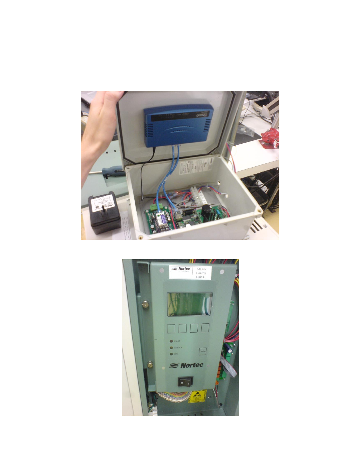
1 Mount the Links 2 remote package in a convenient location. Note that the remote package
does not need to be mounted in close proximity to the humidifier. However, the CAT5 cable
with RJ-45 connection must reach the humidifiers connection on the keypad PCB.
Figure 1: Remote Package
Figure 2: Humidifier Keypad / Front of PCB
Links 2 Retrofit for GSTC / SETC B+, NHTC, NHRS | 2
Page 7
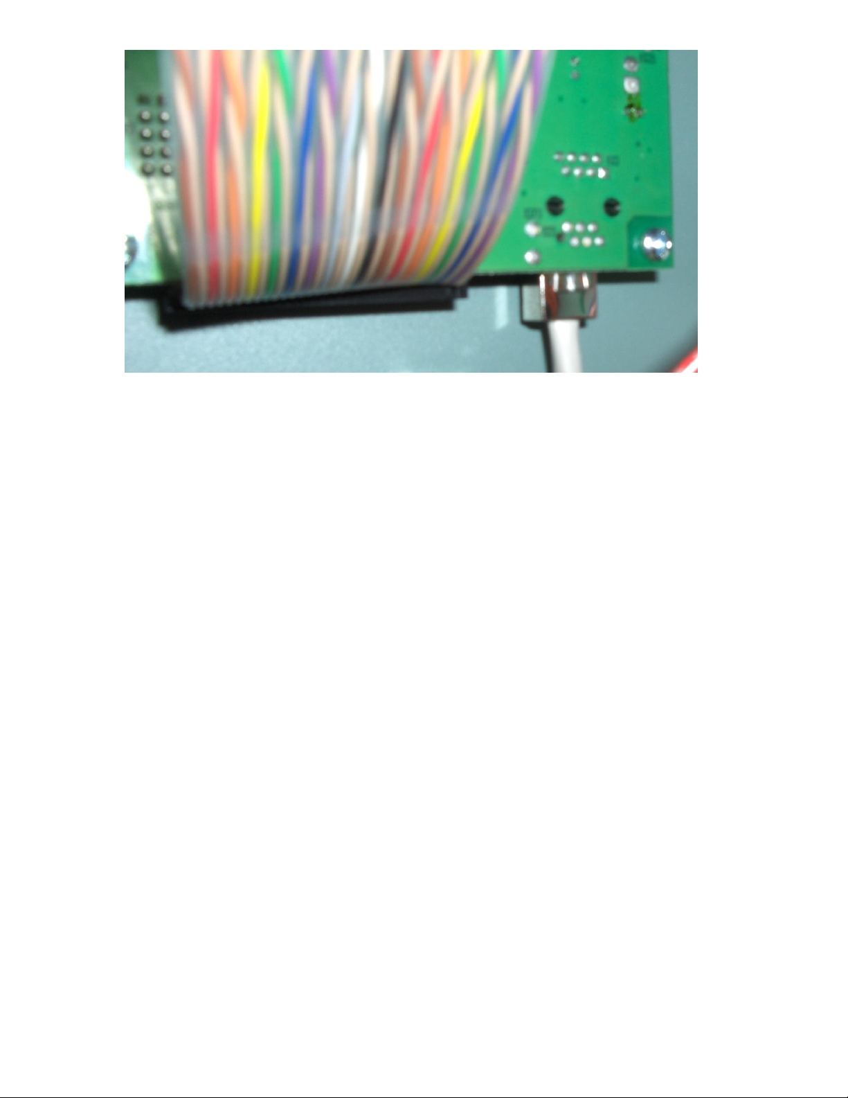
Figure 3: Rear of PCB
2 Connect power to the 24VAC and GND terminals of the LINKS 2 terminal strip. This may be
done in one of two ways:
a A 120VAC to 24VAC plug-in transformer with screw terminals on the secondary side has
been supplied with this kit. Wire the transformer to the 24VAC and GND terminals on the
Links 2 terminal strip.
b Connect power from the humidifier terminal strip (see wiring diagram for details). Power
to Links 2 module will be lost when the humidifier is switched off.
3 Connect the slave humidifiers (if applicable) to the Nortec Links Module. A twisted pair cable
should be used so that the Net + terminal on the Links module should connect to the first
pin (bottom-most pin) of the connector. The Net – terminal on the module should be
connected to the second pin of the connector. Refer to the unit’s wiring diagram for more
information.
Step 2 – Configuring the Humidifiers
Note: If the Links 2 remote package was shipped with the humidifiers, this step will have
already been performed by the factory.
1 Since Nortec Links 2 can connect to a maximum of 8 units, it will be necessary to set the
unit address for each humidifier. The lead unit can be determined by the presence of the
Links 2 module. The slave humidifiers can be given a unit address according to the number
the unit will have on the networked chain.
2 In order to change the current modbus address, press the Menu button on the keypad.
When prompted, enter the code 0335.
3 Once the password is set select the modbus address heading and press enter. Use the up
and down arrows to change the address setting.
4 Determine the desired humidifier ordering on the network. To change the network instance
follow step 3 and enter the parameter value of 2 for unit 2, 3 for unit 3 and so on.
3 | Links 2 Retrofit for GSTC / SETC B+, NHTC, NHRS
Page 8

5th screw
Links 2 – Field Retrofit for GSTC / SETC B+ Models
(BACNET, LONWORKS, and N2 Modules)
Step 1 – Mounting the Links 2 Assembly
1 Install the bracket assembly using 8-32x ½” hex-drive screws. Notice, 4 screws are used for
the hinges, and the 5th screw for fastening the bracket in place.
Figure 4: Bracket Placement and Screw Locations
Figure 5: Detailed View of 5th Screw
Links 2 Retrofit for GSTC / SETC B+, NHTC, NHRS | 4
Page 9

LAN Router or
Switch
(BACnet/IP)
OnLine
Module
LINKS 2
Module
Router
Power
Supply
CAT5
cable
Red and blue
wires
Step 2 – Wiring the Nortec Links 2 Module
1 Most of the wiring connections for the new Nortec LINKS 2 module will have already been
finished at the factory; however, there are a few connections that will need to be made to
connect the unit the GS/SE series humidifier. Refer the LINKs 2 wiring diagram included in
the package for details.
2 Module Power Connections: There will be a wire harness provided that will consist of a red
and blue wire. Both red and blue wires are terminated with a ring terminal.
a The ring terminal of the red wire is to be connected to the power terminal on the 24V
side of the transformer located at the bottom, left of the electrical compartment.
b The ring terminal of the blue wire is to be connected to the ground terminal on the 24V
side of the transformer.
3 Humidifier Communication Connection: On the Nortec LINKS 2 assembly there will be a
CAT5 cable with RJ45 connector.
a This connector is to be plugged into the jack on the bottom right side of the humidifier
main PCB board.
5 | Links 2 Retrofit for GSTC / SETC B+, NHTC, NHRS
Figure 6: Component Identification
Page 10

Step 3 – Configuring the Humidifiers
1 Since Nortec Links 2 can connect to a maximum of 8 units, it will be necessary to set the
unit address for each humidifier. The lead unit can be determined by the presence of the
Links module. The slave humidifiers can be given a unit address according to the number
the unit will have on the networked chain.
2 Press the Menu button on the keypad and enter the code 0335.
3 Select Control Settings
4 Select Modbus Parameters.
5 Set the communication parity to None.
6 Set the appropriate Modbus address according to the unit ordering
7 Place the appropriate Unit Identifier label on each humidifier. These labels should be placed
on the unit where the electrical control punch-outs are located at the top of the humidifier.
8 Connect the slave humidifiers (if applicable) to the Nortec Links Module. A twisted pair cable
should be used so that the Net (+) terminal on the Links module should connect to the first
pin (bottom-most pin) of the connector. The Net (–) terminal on the module should be
connected to the second pin of the connector. Refer to the unit’s wiring diagram for more
information.
9 Ensure shield wiring matches the following pattern if distances between humidifiers is
significant:
Figure 7: Shield Wiring
Links 2 Retrofit for GSTC / SETC B+, NHTC, NHRS | 6
Page 11

LAN Router or
Switch
OnLine
Module
Links 2
Module
Router Power
Supply
Hook
Position
Links 2 – Field Retrofit for NHTC Models
(BACNET, LONWORKS, and N2 Modules)
Figure 8: Component Identification
Step 1 – Mount the Links 2 Assembly
1 The Nortec Links 2 assembly mounts on the top, right corner of the electrical compartment.
2 Ensure that the rear, upwards facing hook engages the proper cooling louver at the back of
the humidifier cabinet.
a Fasten the bracket assembly to the humidifier ‘top’ using the 3 8-32 X ½” self-tapping
screws provided with the kit.
7 | Links 2 Retrofit for GSTC / SETC B+, NHTC, NHRS
Figure 9: Hook Position
Page 12

Screw
locations
Figure 10: Assembly Mounting Location
Links 2 Retrofit for GSTC / SETC B+, NHTC, NHRS | 8
Page 13

CAT5
cable
Ground
Power
Step 2 – Wiring the Nortec Links 2 Module
1 Most of the wiring connections for the new Nortec LINKS 2 module will have already been
finished at the factory; however, there are a few connections that will need to be made to
connect the unit the NHTC series humidifier. Refer the LINKs 2 wiring diagram included in
the package for details.
2 Module Power Connections: There will be a wire harness provided that will consist of a red
and blue wire. Both red and blue wires are terminated with a ring terminal.
a The ring terminal of the red wire is to be connected to the 24V side of the transformer
located at the bottom, left of the electrical compartment.
b The ring terminal of the blue wire is to be connected to the ground terminal on the 24V
side of the transformer
3 Humidifier Communication Connection: On the Nortec Links 2 assembly there will be a CAT5
cable with RJ45 connector.
a This connector is to be plugged into the jack on the bottom right side of the humidifier
mainboard.
Figure 11: Wiring Points
9 | Links 2 Retrofit for GSTC / SETC B+, NHTC, NHRS
Page 14

Step 3 – Configuring the Humidifiers
1 Since Nortec Links 2 can connect to a maximum of 8 units, it will be necessary to set the
unit address for each humidifier. The lead unit can be determined by the presence of the
Links module. The slave humidifiers can be given a unit address according to the number
the unit will have on the networked chain.
2 Press the Menu button on the keypad and enter the password 0459.
3 Scroll down and select Factory Settings.
4 Scroll down and select Core Parameters.
5 Select Modbus Parameters.
6 Set the communication parity to Even.
7 Set the appropriate Modbus address according to the unit ordering.
8 Place the appropriate Unit Identifier label on each humidifier. These labels should be placed
on the unit where the electrical control punch-outs are located at the top of the humidifier.
9 Connect the slave humidifiers (if applicable) to the Nortec Links Module. A twisted pair
cable should be used so that the Net (+) terminal on the Links module should connect to the
Net (+) terminal on the slave unit (NHTC). The Net (–) terminal on the module should be
connected to the Net (–) terminal on the slave unit. Refer to the Links 2 wiring diagram for
more information.
10 Ensure shield wiring matches the following pattern if distance between humidifiers is
significant:
Figure 12: Shield Wiring
Links 2 Retrofit for GSTC / SETC B+, NHTC, NHRS | 10
Page 15

LAN Router or
Switch
OnLine
Module
Links 2
Module
Router Power
Supply
Hook
Position
Links 2 – Field Retrofit for NHRS Models
(BACNET, LONWORKS, and N2 Modules)
Figure 13: Component Identification
Step 1 – Mounting the Links 2 Assembly
1 The Nortec Links 2 assembly mounts on the top, right corner of the electrical compartment.
2 Ensure that the rear, upwards facing hook engages the proper cooling louver at the back of
the humidifier cabinet.
a Fasten the bracket assembly to the humidifier ‘top’ using the 3 8-32 X ½” self-tapping
screws provided with the kit.
11 | Links 2 Retrofit for GSTC / SETC B+, NHTC, NHRS
Figure 14: Hook Position
Page 16

Screw
locations
Figure 15: Assembly Mounting Location
Links 2 Retrofit for GSTC / SETC B+, NHTC, NHRS | 12
Page 17

Step 2 – Wiring the Nortec Links 2 Module
1 Most of the wiring connections for the new Nortec LINKS 2 module will have already been
finished at the factory; however, there is an additional Logic Card that must be installed.
Refer the LINKs 2 wiring diagram included in the package for added details.
2 Module Power Connections: There will be a wire harness provided that will consist of a red
and blue wire. Both red and blue wires are terminated ring terminals. Cut the terminals off
and strip off 1/8” insulation on the end.
a The red wire is to be connected to the left side of contact #1 (24v) on the main terminal strip.
The blue wire is to be connected to the left side of contact #3 (ground) on the main terminal
strip.
Figure 16: Humidifier Man Terminal Strip
13 | Links 2 Retrofit for GSTC / SETC B+, NHTC, NHRS
Page 18

3 Humidifier Communication Connection:
a Locate the main PCB board inside the humidifier.
b Connect the 10 pin end of ribbon cable to the COM port.
Figure 17: COM Port
c Route the ribbon cable through the punch out on the humidifiers front electrical panel
Figure 18: Route Ribbon Cable
Links 2 Retrofit for GSTC / SETC B+, NHTC, NHRS | 14
Page 19

20 pin connection
d Connect the ribbon cable 20 pin side to the Logic Card.
Figure 19: 20 Pin Connection for Ribbon Cable
e Configured dipswitch settings according to MODE1 printed on card (485<>TTL).
Figure 20: Dipswitch Settings for Logic Card
15 | Links 2 Retrofit for GSTC / SETC B+, NHTC, NHRS
Page 20

f Route the RJ-11 cable through the same punch out as the ribbon cable and connect it to the
corresponding jack on the logic card.
Figure 21: RJ-11 Jack Location on Logic Card
g Mount logic card with nylon standoffs and screws to humidifier using the 4 pre-drilled holes
Figure 22: Pre Drilled Holes for Logic Card
Links 2 Retrofit for GSTC / SETC B+, NHTC, NHRS | 16
Page 21

Step 3 – Configuring The Humidifiers
1 Since Nortec Links 2 can connect to a maximum of 8 units, it will be necessary to set the
unit address for each humidifier. The lead unit can be determined by the presence of the
Links module. The slave humidifiers can be given a unit address according to the number
the unit will have on the networked chain.
2 To access the menu settings, press the Up and Down arrows at the same time
3 Scroll up or down to find the Modbus heading
4 Set the appropriate Modbus address according to the unit ordering.
5 Place the appropriate Unit Identifier label on each humidifier. These labels should be placed
on the unit where the electrical control punch-outs are located at the top of the humidifier.
6 Connect the slave humidifiers (if applicable) to the Nortec Links Module. A twisted pair
cable should be used so that the Net (+) terminal on the Links 2 module should connect to
the Net (+) terminal on the slave unit. The Net (–) terminal on the module should be
connected to the Net (–) terminal on the slave unit. Refer to the Links 2 wiring diagram for
more information.
7 Ensure shield wiring matches the following pattern if distance between humidifiers is
significant:
Figure 23: Shield Wiring
17 | Links 2 Retrofit for GSTC / SETC B+, NHTC, NHRS
Page 22

Warranty
Nortec Humidity Ltd. (hereinafter collectively referred to as THE COMPANY), warrant for a period
of two years after installation or 30 months from manufacturer’s ship date, whichever date is
earlier, that THE COMPANY’s manufactured and assembled products, not otherwise expressly
warranted are free from defects in material and workmanship. No warranty is made against
corrosion, deterioration, or suitability of substituted materials used as a result of compliance
with government regulations.
THE COMPANY’s obligations and liabilities under this warranty are limited to furnishing
replacement parts to the customer, F.O.B. THE COMPANY’s factory, providing the defective
part(s) is returned freight prepaid by the customer. Parts used for repairs are warranted for the
balance of the term of the warranty on the original humidifier or 90 days, whichever is longer.
The warranties set forth herein are in lieu of all other warranties expressed or implied by law. No
liability whatsoever shall be attached to THE COMPANY until said products have been paid for in
full and then said liability shall be limited to the original purchase price for the product. Any
further warranty must be in writing, signed by an officer of THE COMPANY.
THE COMPANY’s limited warranty on accessories, not of the companies manufacture, such as
controls, humidistats, pumps, etc. is limited to the warranty of the original equipment
manufacturer from date of original shipment of humidifier.
THE COMPANY makes no warranty and assumes no liability unless the equipment is installed in
strict accordance with a copy of the catalog and installation manual in effect at the date of
purchase and by a contractor approved by THE COMPANY to install such equipment.
THE COMPANY makes no warranty and assumes no liability whatsoever for consequential
damage or damage resulting directly from misapplication, incorrect sizing or lack of proper
maintenance of the equipment.
THE COMPANY makes no warranty and assumes no liability whatsoever for damage resulting
from freezing of the humidifier, supply lines, or drain lines.
THE COMPANY retains the right to change the design, specification and performance criteria of
its products without notice or obligation.
Warranty | 18
Page 23

U.S.A.
1860 Renaissance Blvd.
Sturtevant, WI 53177
826 Proctor Avenue
Ogdensburg, NY 13669
CANADA
2740 Fenton Road
Ottawa, Ontario K1T 3T7
TEL: 1.866.NORTEC1
EMAIL: nortec@humidity.com
WEBSITE: www.humidity.com
 Loading...