

Nortec Links 2 NHTC Installation Manual

TM
NHTC NORTEC
LINKS 2 OPTIONS
Inst allation Manual
Manual No. H-502
2008-02-18
PROPRIETARY NOTICE
This document and the information disclosed herein are proprietary data of WALTER MEIER LTD.
Neither this document nor the information contained herein shall be reproduced used, or disclosed to
others without the written authorization of WALTER MEIER LTD., except to the extent required for
installation or maintenance of recipient’s equipment. All re ferences to the NORTEC name should be
taken as referring to WALTER MEIER LT D.
LIABILITY NOTICE
NORTEC does not accept any liability for installations of humidity equipment installed by unqualified
personnel or the use of parts/components/equipment that are not authorized or approved by
NORTEC.
COPYRIGHT NOTICE
Copyright 2008, WALTER MEIER LTD. All rights reserved.
RECORD OF REVISIONS
For each revision, put the revised pages in your manual and disca rd the superseded pages. W rite the
revision number and revision date, date put in manual, and the incorporator’s initials in the applicable
columns on the Record of Revisions.
Revision
Number
Revision
Date
Date Put
In Manual By
Revision
Number
Revision
Date
Date Put
In Manual By
2008-02-18

TABLE OF CONTENTS
Subject Page
10-00 INTRODUCTION
1. OVERVIEW . . . . . . . . . . . . . . . . . . . . . . . . . . . . . . . . . . . . . . . . . . . . . . . . . . . . . . . . . . . . . . . . . . . . . . . . . . .2
10-10 INSTALLATION PROCEDURES
1. NETWORKING. . . . . . . . . . . . . . . . . . . . . . . . . . . . . . . . . . . . . . . . . . . . . . . . . . . . . . . . . . . . . . . . . . . . . . . . .2
2. WIRING . . . . . . . . . . . . . . . . . . . . . . . . . . . . . . . . . . . . . . . . . . . . . . . . . . . . . . . . . . . . . . . . . . . . . . . . . . . . . .3
A. BACNET/MSTP, JOHNSON N2, AND LONWORKS . . . . . . . . . . . . . . . . . . . . . . . . . . . . . . . . . . . . . . . .3
B. BACNET/IP . . . . . . . . . . . . . . . . . . . . . . . . . . . . . . . . . . . . . . . . . . . . . . . . . . . . . . . . . . . . . . . . . . . . . . . .3
3. GATEWAY CONFIGURATION. . . . . . . . . . . . . . . . . . . . . . . . . . . . . . . . . . . . . . . . . . . . . . . . . . . . . . . . . . . . . 4
4. NETWORK INTEGRATION . . . . . . . . . . . . . . . . . . . . . . . . . . . . . . . . . . . . . . . . . . . . . . . . . . . . . . . . . . . . . . .4
A. LONWORKS.XIF FILE . . . . . . . . . . . . . . . . . . . . . . . . . . . . . . . . . . . . . . . . . . . . . . . . . . . . . . . . . . . . . . .4
B. BACNET PICS AND BIBS. . . . . . . . . . . . . . . . . . . . . . . . . . . . . . . . . . . . . . . . . . . . . . . . . . . . . . . . . . . . . 4
5. VARIABLE DEFINITION. . . . . . . . . . . . . . . . . . . . . . . . . . . . . . . . . . . . . . . . . . . . . . . . . . . . . . . . . . . . . . . . . .5
10-20 START-UP
1. NORTEC LINKS 2 START-UP CHECKLIST . . . . . . . . . . . . . . . . . . . . . . . . . . . . . . . . . . . . . . . . . . . . . . . . . . 2
2. START-UP PROCEDURE . . . . . . . . . . . . . . . . . . . . . . . . . . . . . . . . . . . . . . . . . . . . . . . . . . . . . . . . . . . . . . . .2
10-30 TROUBLESHOOTING
1. TROUBLESHOOTING . . . . . . . . . . . . . . . . . . . . . . . . . . . . . . . . . . . . . . . . . . . . . . . . . . . . . . . . . . . . . . . . . .2
2. INDICATOR LIGHTS . . . . . . . . . . . . . . . . . . . . . . . . . . . . . . . . . . . . . . . . . . . . . . . . . . . . . . . . . . . . . . . . . . . .2
10-40 SPARE PARTS
1. REPLACEMENT PARTS . . . . . . . . . . . . . . . . . . . . . . . . . . . . . . . . . . . . . . . . . . . . . . . . . . . . . . . . . . . . . . . . .2
10-50 TECHNICAL
1. WIRING DIAGRAMS . . . . . . . . . . . . . . . . . . . . . . . . . . . . . . . . . . . . . . . . . . . . . . . . . . . . . . . . . . . . . . . . . . . .2
WARRANTY
2008-02-18

LIST OF FIGURES
Figure Page
10-10 INSTALLATION
Figure 1. Sample Humidification Applications - Room-Sensed %RH Feedback with Duct Hi-Limit Sensing .16
Figure 2. Sample Humidification Applications - Control Feedba ck (0-100%) with Duct Hi-Limit Sensing. . . .16
Figure 3. Sample Humidification Applications - 0-10V Signal Directly to Humidifier) . . . . . . . . . . . . . . . . . . .17
10-30 TROUBLESHOOTING
Figure 1. OnLine Diagnostic LED Locations . . . . . . . . . . . . . . . . . . . . . . . . . . . . . . . . . . . . . . . . . . . . . . . . . . .3
Figure 2. BACnet Module LED . . . . . . . . . . . . . . . . . . . . . . . . . . . . . . . . . . . . . . . . . . . . . . . . . . . . . . . . . . . . .3
Figure 3. LonWorks Module LED. . . . . . . . . . . . . . . . . . . . . . . . . . . . . . . . . . . . . . . . . . . . . . . . . . . . . . . . . . . .3
Figure 4. Ethernet Port . . . . . . . . . . . . . . . . . . . . . . . . . . . . . . . . . . . . . . . . . . . . . . . . . . . . . . . . . . . . . . . . . . .3
10-40 SPARE PARTS
Figure 1. BACnet or N2 Module. . . . . . . . . . . . . . . . . . . . . . . . . . . . . . . . . . . . . . . . . . . . . . . . . . . . . . . . . . . . .3
Figure 2. LonWorks Module. . . . . . . . . . . . . . . . . . . . . . . . . . . . . . . . . . . . . . . . . . . . . . . . . . . . . . . . . . . . . . . .3
Figure 3. OnLine Module. . . . . . . . . . . . . . . . . . . . . . . . . . . . . . . . . . . . . . . . . . . . . . . . . . . . . . . . . . . . . . . . . .3
Figure 4. Ethernet Router . . . . . . . . . . . . . . . . . . . . . . . . . . . . . . . . . . . . . . . . . . . . . . . . . . . . . . . . . . . . . . . . .3
Figure 5. Ethernet Swithch . . . . . . . . . . . . . . . . . . . . . . . . . . . . . . . . . . . . . . . . . . . . . . . . . . . . . . . . . . . . . . . .4
10-50 TECHNICAL
Figure 1. Wiring Diagram - NHTC LINKS II BACnet/IP Option . . . . . . . . . . . . . . . . . . . . . . . . . . . . . . . . . . . . .2
Figure 2. Wiring Diagram - NHTC LINKS II LonWorks Option. . . . . . . . . . . . . . . . . . . . . . . . . . . . . . . . . . . . . .3
Figure 3. Wiring Diagram - NHTC LINKS II Option . . . . . . . . . . . . . . . . . . . . . . . . . . . . . . . . . . . . . . . . . . . . . .4
LIST OF TABLES
Table Page
10-00 INTRODUCTION
Table 1. Protocol Options. . . . . . . . . . . . . . . . . . . . . . . . . . . . . . . . . . . . . . . . . . . . . . . . . . . . . . . . . . . . . . . . .2
10-10 INSTALLATION
Table 1. Recommended Wire Types and Lengths . . . . . . . . . . . . . . . . . . . . . . . . . . . . . . . . . . . . . . . . . . . . .3
Table 2. Baud Rates . . . . . . . . . . . . . . . . . . . . . . . . . . . . . . . . . . . . . . . . . . . . . . . . . . . . . . . . . . . . . . . . . . . .4
Table 3. Variable Definitions. . . . . . . . . . . . . . . . . . . . . . . . . . . . . . . . . . . . . . . . . . . . . . . . . . . . . . . . . . . . . . .6
Table 4. Variable Addresses Unit #1 . . . . . . . . . . . . . . . . . . . . . . . . . . . . . . . . . . . . . . . . . . . . . . . . . . . . . . . .8
Table 5. Variable Addresses Unit #2 . . . . . . . . . . . . . . . . . . . . . . . . . . . . . . . . . . . . . . . . . . . . . . . . . . . . . . . .9
Table 6. Variable Addresses Unit #3 . . . . . . . . . . . . . . . . . . . . . . . . . . . . . . . . . . . . . . . . . . . . . . . . . . . . . . .10
Table 7. Variable Addresses Unit #4 . . . . . . . . . . . . . . . . . . . . . . . . . . . . . . . . . . . . . . . . . . . . . . . . . . . . . . .11
Table 8. Variable Addresses Unit #5 . . . . . . . . . . . . . . . . . . . . . . . . . . . . . . . . . . . . . . . . . . . . . . . . . . . . . . .12
Table 9. Variable Addresses Unit #6 . . . . . . . . . . . . . . . . . . . . . . . . . . . . . . . . . . . . . . . . . . . . . . . . . . . . . . .13
Table 10. Variable Addresses Unit #7 . . . . . . . . . . . . . . . . . . . . . . . . . . . . . . . . . . . . . . . . . . . . . . . . . . . . . . .14
Table 11. Variable Addresses Unit #8 . . . . . . . . . . . . . . . . . . . . . . . . . . . . . . . . . . . . . . . . . . . . . . . . . . . . . . .15
10-30 TROUBLESHOOTING
Table 1. OnLine Diagnostic LED Description . . . . . . . . . . . . . . . . . . . . . . . . . . . . . . . . . . . . . . . . . . . . . . . . . .4
Table 2. LINKS 2 Module Diagnostic LEDs . . . . . . . . . . . . . . . . . . . . . . . . . . . . . . . . . . . . . . . . . . . . . . . . . . .5
Table 3. Troubleshooting Communication Problems . . . . . . . . . . . . . . . . . . . . . . . . . . . . . . . . . . . . . . . . . . . .6
10-40 SPARE PARTS
Table 1. Replacement Parts. . . . . . . . . . . . . . . . . . . . . . . . . . . . . . . . . . . . . . . . . . . . . . . . . . . . . . . . . . . . . . .2
2008-02-18

THIS PAGE INTENTIONALLY LEFT BLANK
2008-02-18

10-00
INTRODUCTION
10-00
Page 1
2008-02-18
(1) OVERVIEW
(1) The NHTC Nortec LINKS 2 Option allows for the integration of a NHTC Series
humidifier within a BACnet, Johnson N2 or LonWorks network and allows those units
to concurrently be monitored via the Nortec OnLine interface. This option features a
Nortec OnLine module co-existing with a gateway that has the capability of
converting information from the host Modbus protocol to a specified secondary
protocol.
(2) The following protocol options are available and must be specified when ordering:
Table 1. Protocol Options
Protocol Default Baud Rates
BACnet MS/TP 38.4 kbps
BACnet / IP 10BaseT
Johnson N2 9.6 kbps
10-00
Page 2
2008-02-18

10-10
INSTALLATION
10-10
Page 1
2008-02-18

(1) NETWORKING
(1) It is possible to network up to a maximum of 8 units to a single LINKS 2. Since each
unit is separately addressed, it is possible to monitor and control each unit
individually. Different networking configurations may be achieved and are mostly
dependant on the type of network present at the site. One networking example could
have a Gateway installed inside the lead unit, which could then be daisy-chained to
successive units. In turn, the lead unit would connect to a Building Management
System (BMS) network via a shielded, twisted-pair connection. Please see wiring
section for additional detail. A second example could have a series of units directly
connected to an Ethernet network. This is only possible for BACnet communication
and is essentially referred to as a BACnet/IP configuration.
10-10
Page 2
2008-02-18
(2) WIRING
(A) BACNET/MSTP, JOHN SON N2, AND LONWORKS
(1) The necessary internal wiring for the Gateway is already present except for the BMS
network connection that can be made via twisted-pair at terminals A and B. To
network multiple units to a single Gateway, the units may be daisy-chained to each
other using the network link terminals at the TB3 connection jack on the humidifier
logic board. Refer to wiring diagram in section 10-50.
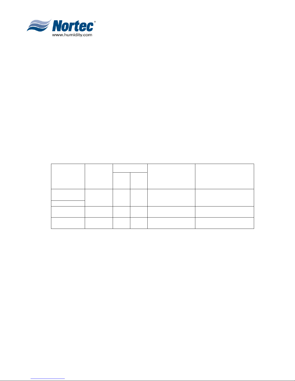
(1) Table #1 refers to the recommended wire types and maximum recommended
lengths from the Nortec LINK 2 module to the front-end of the Building Management
system. Since communication between the humidifiers and Nortec Links will always
occur via a EIA-485 signal type, Nortec recommends using a 18-24 AWG shielded,
twisted pair wire between the lead humidifier and each of the slave humidifiers.
Cable runs between the Nortec LINKS 2 module and the furthest slave humidifier
should not exceed 2,000 feet. Signal boosters or repeaters may be necessary for
longer wire runs or where electrical noise interference is prevalent.
Table 1. Recommended Wire Types and Lengths
Polarity
Protocol
Signal
Type
A B
Recommended
Cable
Maximum
Recommended
Distance from Nortec
Module
BACnet
MS/TP
Johnson N2
BACnet/IP
LonWorks
(B) BACNET/IP
(1) The necessary wiring for the Gateway is present except for the network cable,
EIA-485,
2-wire
LAN
standard
EIA-232,
2-wire
Net + Net -
N/A N/A
Tx
Rx
18-24 AWG
Shielded, Twisted
Pair
CAT.5E cable with
RJ-45 termination
18-24 AWG
Twisted Pair
2300 ft at 9.600 kbps
2000 ft at 38,400 kbps
Depends on cable
manufacturer
Should not exceed 50 ft.
which must be connected to the RJ-45 (Ethernet) jack on the Gateway. Refer to
wiring diagram in section 10-50.
10-10
Page 3
2008-02-18
(3) GATEWAY CONFIGURATION
(1) Protocol configuration is made at the factory, prior to final testing. Baud rates are
also adjusted to the following values:
Table 2. Baud Rates
Protocol Default Baud Rates
BACnet MS/TP 38.4 kbps
BACnet / IP 10BaseT
Johnson N2 9.6 kbps
(2) For BACnet/IP, BACnet/MSTP and Johnson N2 applications, it is necessary to
establish the modules network address parameters in order access it. Address
assignments can be configured at the factory or Nortec can provide instructions to
modify the address settings in the field.
(4) NETWORK INTEGRATION
(A) LONWORKS.XIF FILE
(1) To facilitate the integration of a LonWorks unit within a network, it may be desirable
to obtain an Ex
resources, specific objects and data types which a LonWorks device possesses. The
.xif file allows a network integrator to simulate the presence of a networked humidifier
even if it is not yet physically connected to the network. In fact, if the integrator has
the .xif files of all network devices, a complete system could be simulated and
configured off-line. Once the configuration is done, the integrator's software tool can
be connected to the actual system and the configuration information can be
downloaded. If a .xif file is required prior to installing a LonWorks-enabled humidifier,
please contact the factory to obtain it.
ternal Interface File (XIF). Files of type .xif are used to convey the
(B) BACNET PICS AND BIBS
(1) The Protocol Implementation Conformance Statement or “PICS” describes the
BACnet capabilities of a particular BACnet implementation. It is a written document,
created by the manufacturer of a device, which identifies the particular options
specified by BACnet that are implemented in the device.
(2) BACnet Interoperability Building Blocks (BIBBs) describe a list of services a BACnet
device provides. The main areas that the building blocks are concerned with include:
data sharing, trends, schedules, device and system management. BIBBs help
specify the interoperability capabilities of a BACnet device. Please contact the
factory to obtain a PICS statement or BIBBs profile.
10-10
Page 4
2008-02-18

(5) VARIABLE DEFINITION
In the variable name, “_x” denotes the humidifier number. If there is only one
GSTC humidifier, all variable names will end in “_1”. If two units are networked
together (see Figure 4), the second unit’s variable names will end in “_2”. For 3
networked units, “_3” and so on. If unsure of the unit number, each unit will have a
label indicating the device instance of each humidifier. If unsure of the unit number,
each unit will have a label, in the electrical compartment close to the terminal strip,
indicating the device instance of each humidifier.
(1) Nortec LINKS 2 monitors a variety of variables for each unit that is connected to it.
For a variable listing and definition refer to Table 3. Network variable addresses for
the humidifiers may be seen in Table 4 to Table 11.
IMPORTANT:
10-10
Page 5
2008-02-18

Table 3. Variable Definitions
Variable Name
nvoHourOpt_x
nvoCapLimit
nvoRHDem1_x
nvoSet1_x
nvoRHDem2_x
nvoSet2_x
R=Read
W=Write
R
Analogue Value
R
Analogue Value
R
Analogue Value
R
Analogue Value
R
Analogue Value
R
Analogue Value
Description LonWorks SNVT
Indicates the number of hours the
humidifier cylinder has been in
operation.
Reads to capacity limitation
applied to the unit output.
(50-100%)
Reads Ch.1 input signal in %RH
or demand to humidifier.
(0-100%)
Reads Ch.1 setpoint setting.
(10-90%)
Reads Ch.2 input signal in %RH
or demand to humidifier.
(0-100%)
Unit must be configured for dual
channel operation.
Reads Ch.2 setpoint setting.
(10-90%)
Unit must be configured for dual
channel operation.
SNVT_count_inc
SNVT_switch
SNVT_switch
SNVT_switch
SNVT_switch
SNVT_switch
nvoSysDemand_x
nviCapLimit
nviRHDem1_x
nviRHDem2_x
nviSet1_x
nviSet2_x
R
Analogue Value
R
Analogue Value
W
Analogue Value
W
Analogue Value
W
Analogue Value
W
Analogue Value
Reads humidifier system
demand. (0-100%)
Sets the humidifier’s unit
capacity. (50-100%)
Writes Ch.1 demand or %RH
level. Allows BMS control of
humidifier output. (0-100%)
Unit must be configured for
networked demand
Writes Ch.2 demand or %RH
level. Allows BMS control of
humidifier output. (0-100%)
Unit must be configured for
networked demand
Writes Ch.1 setpoint (0-90%) SNVT_switch
Writes Ch.2 setpoint (0-90%) SNVT_switch
SNVT_switch
SNVT_switch
SNVT_switch
10-10
Page 6
2008-02-18

Variable Name
nvoFault_x
nvoHWSensor_x
nvoNetSensor_x
nvoDisable_x
nvoSecurity_x
R=Read
W=Write
R
Binary Value
R
Binary Value
R
Binary Value
R
Binary Value
R
Binary
Description LonWorks SNVT
Indicates unit fault status.
0=no fault, 1=fault.
Indicates if a high-water level
condition exists in the humidifier
cylinder.
0=normal, 1=high water condition
Reads configuration status for
network-enabled sensing or
control.
0=%RH or %demand input is not
from the network
1=%RH or %demand input is
the network
Reads remote disable status.
0=humidifier enabled,
1=humidifier disabled by network
Indicates security loop status.
0=Sec. loop open,
1=Sec. loop closed
from
SNVT_switch
SNVT_switch
SNVT_switch
SNVT_switch
nvoService_x
nvoStatus_x
nvoConnection_x
nviDisable_x
nviNetSensor _x
R
Binary Value
R
Binary Value
R
Binary Value
W
Binary Value
W
Binary Value
Reads service requirement status.
0=no service required,
1=service required
Reads humidifier status.
0=standby, 1=humidifying.
Indicates that the Nortec Links
module is communicating with the
Humidifier
Writes remote disable status.
0=humidifier enabled,
1=humidifier disabled from
network
Writes configuration status for
network-enabled sensing or
control.
0=%RH or %demand input is not
from the network
1=%RH or %demand input is
the network
from
SNVT_switch
SNVT_switch
SNVT_switch
SNVT_switch
SNVT_switch
10-10
Page 7
2008-02-18
 Loading...