

Page 1
Important: Read and save these instructions. This guide to be left with equipment.
2531037-E | 21 FEB 2012
LINKS 2
GSTC / SETC
B+ Models
Installation and
Operation Manual
Includes installation, operation
maintenance and troubleshooting
information for your GSTC/SETC B+
Nortec Links2 Options.
Page 2

INSTALLATION DATE (MM/DD/YYYY)
MODEL #
SERIAL #
Thank you for choosing NORTEC.
Proprietary Notice
This document and the information disclosed herein are proprietary data of Nortec Humidity Ltd. Neither this
document nor the information contained herein shall be reproduced used, or disclosed to others without the
written authorization of Nortec Humidity Ltd., except to the extent required for installation or maintenance of
recipient’s equipment.
Liability Notice
Nortec does not accept any liability for installations of humidity equipment installed by unqualified personnel or
the use of parts/components/equipment that are not authorized or approved by Nortec.
Copyright Notice
Copyright 2012, Nortec Humidity Ltd. All rights reserved.
Page 3

Contents
1 Installation
1 Overview
1 Bracket Installation
2 Retrofit Insallation of a NHRS
Links 2 Package
3 Mount the Links 2 Assembly
4 Wiring the Nortec Links 2 Module
9 Multi-Unit Systems (Master /
Slave)
9 Wiring
11 Network Integration
12 Retrieving XIF File Instructions
15 Variable Definition
26 Startup Check List
27 Troubleshooting
27 Indicator Lights
32 Replacement Parts
36 Wiring Diagrams
Page 4

Page 5

Overview
Protocol
BACnet MS/TP
BACnet / IP
Johnson N2
LonWorks
The GS/SE Nortec Links2 Option allows for the integration of a GSTC or SETC Series humidifier
within a BACnet, Johnson N2 or LonWorks network and allows those units to concurrently be
monitored via the Nortec OnLine interface. This option features a Nortec OnLine module coexisting with a gateway that has the capability of converting information from the host Modbus
protocol to a specified secondary protocol.
The following protocol options are available, and must be specified at time of order:
Table 1: Protocol Options
The Nortec Links2 package also includes Nortec OnLine. Nortec OnLine is an advanced web
monitoring package that allows authorized users to remotely monitor humidifier status and
performance from anywhere with an internet connection. Nortec OnLine is available with an
optional service that, among other things, includes factory technicians monitoring the units
weekly. Even if the OnLine service is not ordered, the units can still be connected to an viewed
online at www.norteconline.com For information specifically related to Nortec OnLine consult the
accompanying OnLine manual or your local representative.
Bracket Installation
Links2 can be factory installed inside of the humidifier if the package is included at time of order.
If this is the case, skip ahead through this section.
Links2 can also be retrofit to existing units. The following section explains how to install the
Links2 bracket inside of the humidifier.
Installation| 1
Page 6
Retrofit Installation Of A SETC-50 Nortec Links 2 Package
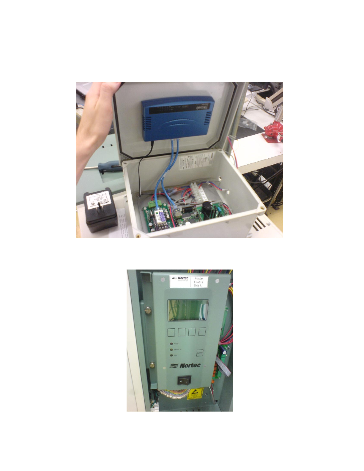
Step 1 - Installation
Mount the Links2 remote package in a convenient location. Note that the remote package does
not need to be mounted in close proximity to the humidifier, however, the CAT5 cable with RJ-45
connection must reach the humidifiers connection on the keybad PCB.
Figure 1: Remote Package
2 | Installation
Figure 2: Humidifier Keypad/Front of PCB
Page 7
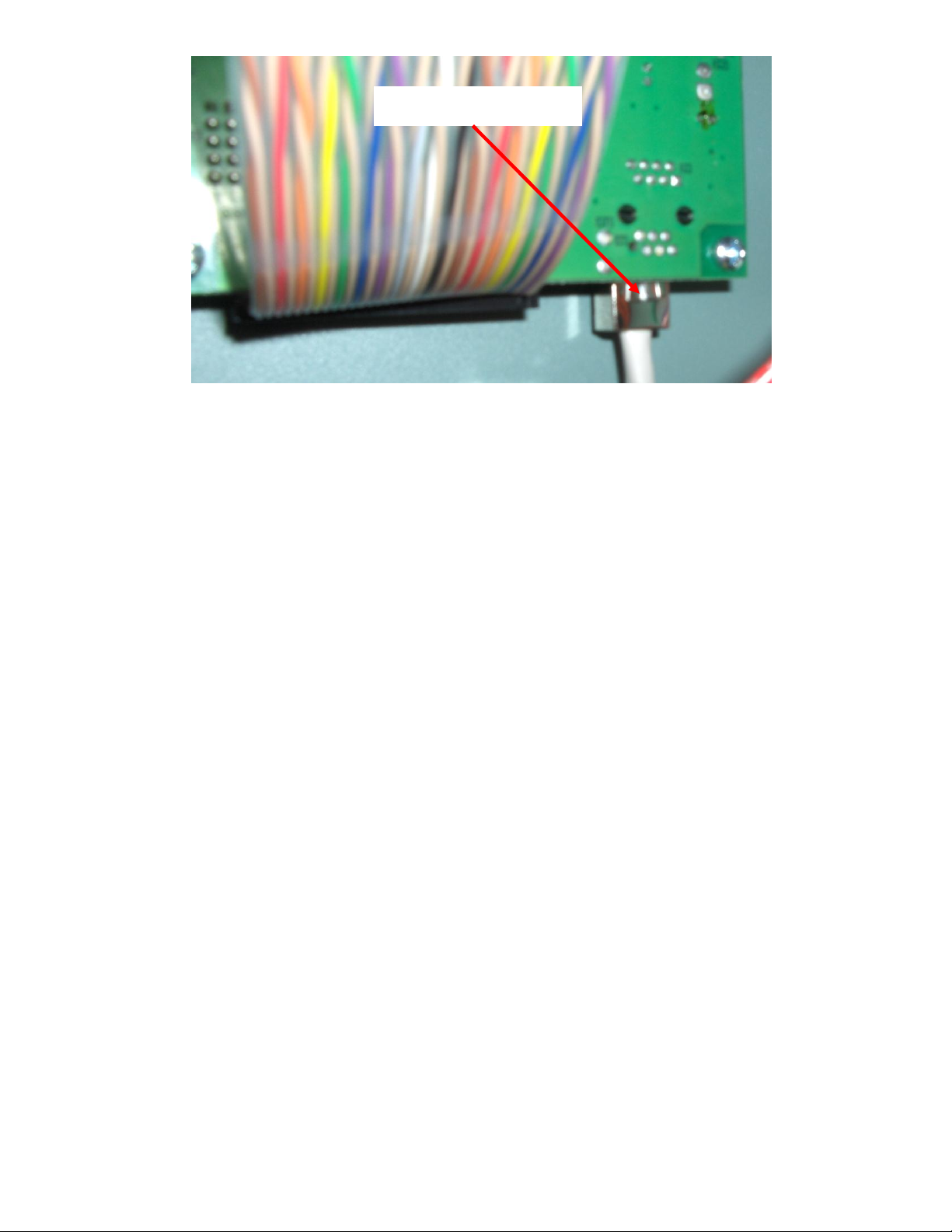
RJ-45 connected
Figure 3: Rear of PCB
Connect power to the 24VAC and GND terminals of the Links2 terminal strip. This may be done in
one of two ways:
1. A 120VAC to 24VAC plug-in transformer with screw terminals on the secondary side has been
supplied with this kit. Wire the transformer to the 24VAC and GND terminals on the Links2
terminal strip.
2. Connect power from the humidifier terminal strip (see wiring diagram for details).
3. Note on 2(b) - Power to Links2 module will be lost when the humidifier is switched off.
4. Connect the slave humidifiers (if applicable) to the Nortec Links Module. A twisted pair cable
should be used so that the Net + terminal on the Links module should connect to the first pin
(bottom-most pin) of the connector. The Net – terminal on the module should be connected to
the second pin of the connector. Refer to the unit’s wiring diagram for more information.
Step 2 – Configuring The Humidifiers
Note: If the Links2 remote package was shipped with the humidifiers, this step will have already
been performed by the factory.
1. Since Nortec Links2 can connect to a maximum of 8 units, it will be necessary to set the unit
address for each humidifier. The lead unit can be determined by the presence of the Links2
module. The slave humidifiers can be given a unit address according to the number the unit
will have on the networked chain.
2. In order to change the current modbus address, press the Menu button on the keypad. When
prompted, enter the code 0335.
3. Once the password is set select the modbus address heading and press enter. Use the up and
down arrows to change the address setting.
4. Determine the desired humidifier ordering on the network. To change the network instance
follow step 3 and enter the parameter value of 2 for unit 2, 3 for unit 3 and so on.
Installation| 3
Page 8
Retrofit Installation Of A GSTC/SETC Nortec Links2 Package
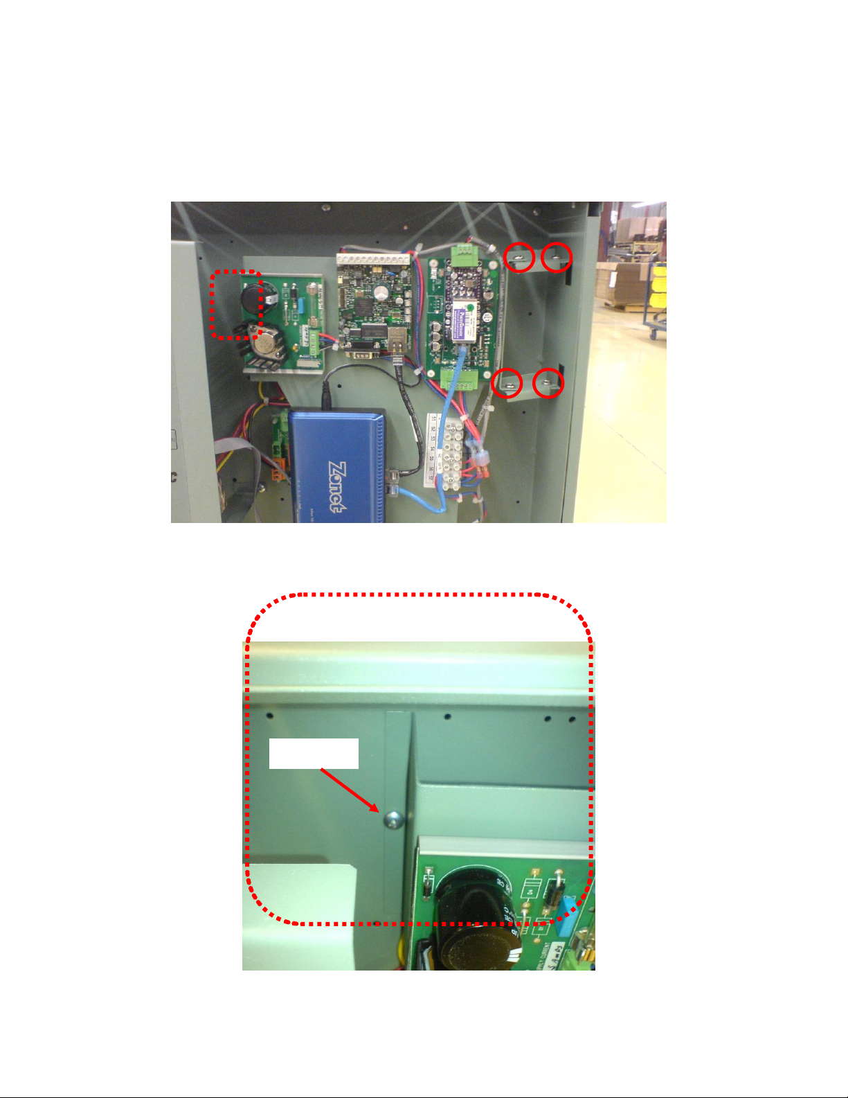
Figure 1. Bracket Placement and Screw Locations
Figure 2. Detailed View of 5th Screw
5th screw
BACNET, LONWORKS And N2 Modules:
Mounting The Links2 Assembly
Install the bracket assembly using 8-32x ½” hex-drive screws. Notice, 4 screws are used for the
hinges, and the 5th screw for fastening the bracket in place.
4 | Installation
Page 9
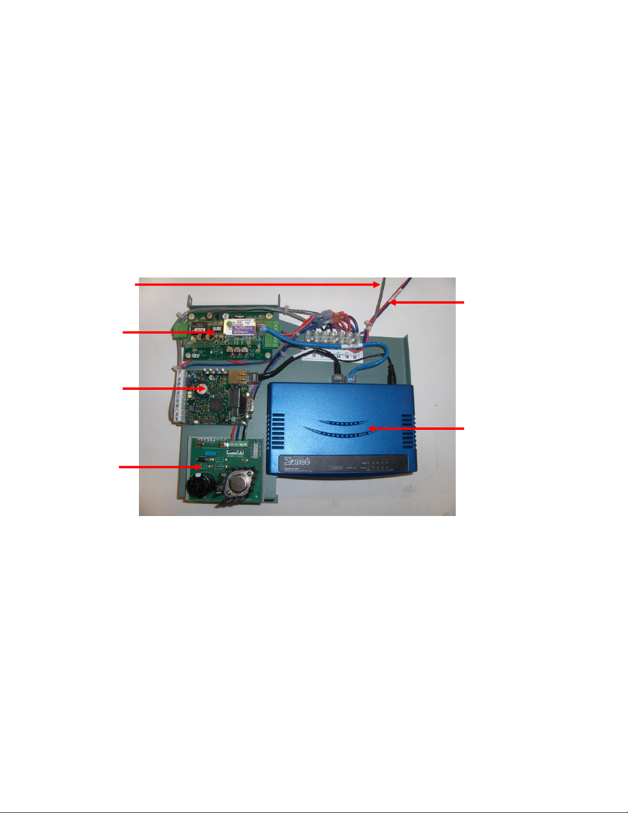
Wiring The Nortec Links2 Module
Figure 3. Component Identification
LAN
Router or
OnLine
LINKS 2
Router
CAT5 cable
Red and
blue wires
Most of the wiring connections for the new Nortec Links2 module will have already been finished at
the factory, however, there are a few connections that will need to be made to connect the unit the
GS/SE series humidifier. Refer the Links2 wiring diagram included in the package for details.
Module Power Connections: There will be a wire harness provided that will consist of a red and blue
wire. Both red and blue wires are terminated with a ring terminal.
1. The ring terminal of the red wire is to be connected to the power terminal on the 24V side of the
transformer located at the bottom, left of the electrical compartment.
2. The ring terminal of the blue wire is to be connected to the ground terminal on the 24V side of the
transformer.
Humidifier Communication Connection: On the Nortec LINKS 2 assembly there will be a CAT5 cable
with RJ45 connector.
1. This connector is to be plugged into the jack on the bottom right side of the humidifier main PCB
board.
Installation| 5
Page 10
Configuring The Humidifiers
Since Nortec Links2 can connect to a maximum of 8 units, it will be necessary to set the unit address
for each humidifier. The lead unit can be determined by the presence of the Links module. The slave
humidifiers can be given a unit address according to the number the unit will have on the networked
chain.
1. Press the Menu button on the keypad and enter the code 0335.
2. Select Control Settings
3. Select Modbus Paramaters.
4. Set the communication parity to None.
5. Set the appropriate Modbus address according to the unit ordering
6. Place the appropriate Unit Identifier label on each humidifier. These labels should be placed on
the unit where the electrical control punch-outs are located at the top of the humidifier.
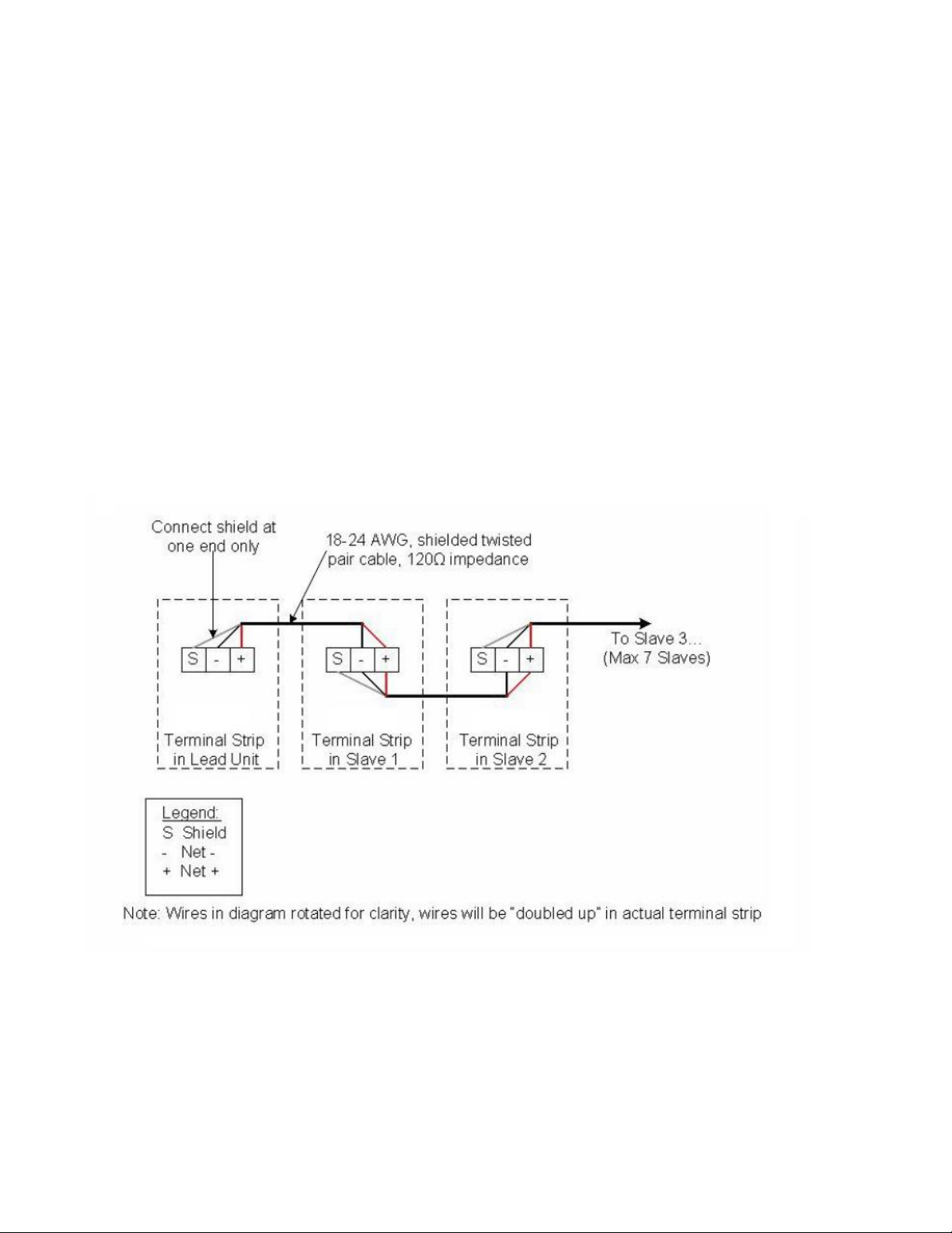
7. Connect the slave humidifiers (if applicable) to the Nortec Links Module. A twisted pair cable
should be used so that the Net (+) terminal on the Links module should connect to the first pin
(bottom-most pin) of the connector. The Net (–) terminal on the module should be connected to
the second pin of the connector. Refer to the unit’s wiring diagram for more information.
8. Ensure shield wiring matches the following pattern if distances between humidifiers is significant.
6 | Installation
Page 11

Multi-Unit Systems (“Master/Slave”)
Up to 8 humidifiers can be chained and monitored through a single Links2 package. In this
configuration, the unit with the Links2 package is designated the “Master Unit”, while the
remaining 7 humidifiers are configured as “Slaves”. The master unit is connected to the Building
Management Systems (BMS). Each unit is separately addressed, it is possible to monitor and
control each unit individually.
Different networking configurations may be achieved depending on the type of network being
used. One networking example could have a Gateway installed inside the lead unit, which could
then be daisy-chained to successive units. In turn, the lead unit would connect to a Building
Management System (BMS) network via a shielded, twisted-pair connection. Please see wiring
section for additional detail. A second example could have a series of units directly connected to
an Ethernet network. This is only possible for BACnet communication and is essentially referred to
as a BACnet/IP configuration.
Installation| 7
Page 12
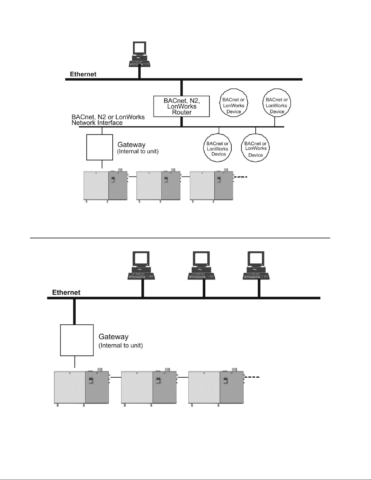
Figure 1: Sample Network with Nortec Links 2
Figure 2: For BACnet IP only
GS/SE (1) GS/SE (2) GS/SE (3)
GS/SE (1) GS/SE (2) GS/SE (3)
8 | Installation
Page 13

Wiring
Protocol
Signal Type
Polarity
Recommended Cable
Maximum Recommended
Distance from Nortec
Module
A
B
BACnet MS/TP
EIA-485,
2-wire
Net +
Net -
18-24 AWG
Shielded, Twisted Pair
2000 ft at 9,600 bps
2000 ft at 38,400 kbps
Johnson N2
BACnet/IP
LAN standard
N/A
N/A
CAT.5E cable with RJ-
45 termination
Depends on cable
manufacturer
LonWorks
FTT-10,
2-wire
Tx
Rx
18-24 AWG
Twisted Pair
Should not exceed 50 ft.
BACnet MS/TP, Johnson N2, and LonWorks
Links2 is pre-installed and factory wired, except for the SETC-050 which is provided in its own
separate enclosure. Connections must be made between the master humidifier and the Building
Management System (BMS), and the master humidifier and any slaves that may be present.
Up to 8 units (1 master, 7 slaves) may be connected to a BMS through a single gateway in the
master unit. The units are daisy chained via the Links / Online terminal strip. The wire shield
should only be connected at one end per pair of units when “daisy chaining”. Older A and B style
units use a different connection method, please refer to revision C of this manual.
Table 2 refers to the recommended wire types and maximum recommended lengths from the
Nortec Links2 module to the front-end of the Building Management System. Since communication
between the humidifiers and Nortec Links 2 occurs via a EIA-485 signal type, Nortec recommends
using a 18-24 AWG shielded, 120 twisted pair wire between the lead humidifier and each of the
slave humidifiers. Total cable length runs between the Nortec Links2 module and the furthest
slave humidifier should not exceed 2,000 feet. Signal boosters or repeaters may be necessary for
longer wire runs or where electrical noise interference is prevalent.
Table 2: Recommended Wire Types and Lengths
BACnet/IP
A standard CAT-5E cable with an RJ-45 ethernet jack is to be connected to port 3,4, or 5 on the
gateway. Refer to wiring diagrams in this manual.
Installation| 9
Page 14

Gateway Configuration
Protocol
Default Baud Rates
BACnet MS/TP
38.4 kbps
BACnet / IP
10BaseT
Johnson N2
9.6 kbps
LonWorks
38.4 kbps
Protocol configuration is made at the factory, prior to final testing. Baud rates are adjusted to the
following values by default.
Table 3: Baud Rates
For BACnet/IP, BACnet/MSTP and Johnson N2 applications, it is necessary to establish the
modules network address parameters in order access it. Address assignments can be configured
at the factory or Nortec can provide instructions to modify the address settings in the field.
LonWorks networks can automatically detect network address parameters and do not need
further configuration.
Network Integration
LonWorks.xif file
To facilitate the integration of a LonWorks unit within a network, it may be desirable to obtain an
External Interface File (XIF). Files of type .xif are used to convey the resources, specific objects
and data types which a LonWorks device possesses. The .xif file allows a network integrator to
simulate the presence of a networked humidifier even if it is not yet physically connected to the
network. In fact, if the integrator has the .xif files of all network devices, a complete system could
be simulated and configured off-line. Once the configuration is done, the integrator's software tool
can be connected to the actual system and the configuration information can be downloaded.
10 | Installation
Page 15
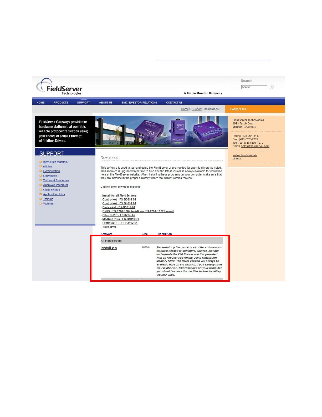
Retrieving XIF file instructions
The XIF file can be retrieved directly from the Links package. A Windows based laptop and an
Ethernet cable are required for this process. This process requires the “Remote User Interface”
tool from Fieldserver. It is available by visiting http://fieldserver.com/techsupport/utility/utility.php and
downloading the “Utility” software:
Once this software has been installed, follow the following procedure:
1. Locate desired MASTER humidifier that contains the Links package. Ensure unit is powered
on and remove the panel on the RIGHT side of the humidifier. Locate the Links package inside
of the unit.
2. For LINKS2 packages (with the blue ZONET router), connect one end of the CAT5 cable to the
router in an available port (ports 3 or 4 should be free) NOTE: Do NOT plug into the “WAN”
port.
For LINKS XPS packages (gateway device on its own), connect the CAT5 cable directly into the
Ethernet port on the gateway.
Installation| 11
Page 16

3. Connect other end of CAT5 cable to the Ethernet port on the laptop.
4. Run the “Remote User Interface” utility by double clicking the shortcut on your desktop (or
Start>Programs>Fieldserver Utilities>Remote User Interface)
5. The program should automatically recognize connected humidifier and bring you to the “Main
Menu”. If it does not, contact Nortec Technical Services at the number on the back cover of
this manual.
6. Type “u” for upload.
7. Type “o” for other. (A warning will appear, press any key to continue.)
8. Type “r” for remote.
9. Enter “fserver.xif”’ and hit the ‘enter’ key.
10. Type “u” to initiate upload from the gateway to the laptop.
11. The .xif file will be saved in the folder “Configuration File Folder” located at
Start>Programs>Fieldserver Utilities>Configuration File Folder.
12. Type ‘q’ twice to exit out of the program
13. Locate file in Configuration File Folder and change name to corresponding humidifier, (ex,
“fserverH1.xif” for Humidifier 1)
14. Repeat this procedure for all Master humidifiers changing the name of the .xif once saved to
correspond with the tag of the appropriate humidifier.
12 | Installation
Page 17

BACnet Pics and Bibs
In the variable name, “_x” denotes the humidifier number. If there is only one humidifier,
all variable names will end in “_1”. If two units are networked together, see Figure 4, the
second unit’s variable names will end in “_2”. For 3 networked units, “_3” and so on. If
unsure of the unit number, each unit will have a label, in the electrical compartment close
to the terminal strip, indicating the device instance of each humidifier.
The Protocol Implementation Conformance Statement or “PICS” describes the BACnet capabilities
of a particular BACnet implementation. It is a written document, created by the manufacturer of a
device, which identifies the particular options specified by BACnet that are implemented in the
device. Please refer to the wiring diagram section for a PICS statement.
BACnet Interoperability Building Blocks (BIBBs) describe a list of services a BACnet device
provides. The main areas that the building blocks are concerned with include: data sharing,
trends, schedules, device and system management. BIBBs help specify the interoperability
capabilities of a BACnet device. Please contact the factory to obtain a PICS statement or BIBBs
profile.
NORTEC OnLine
Firewall Port 5222 must be open to TCP traffic in order for NORTEC OnLine to communicate
properly.
Variable Definition
Nortec Links2 is capable of communicating a variety of variables for each unit that is connected to
it. For a variable listing and definition refer to Table 4. Network variable addresses for the
humidifiers may be seen in Table 5 to Table 12.
Installation| 13
Page 18

Variable Name
R=Read
W=Write
Description
LonWorks SNVT
nvoRHDem1_x
R
Analog Value
Reads %RH in space or %demand
to humidifier. (0%-100%) Choice
determined by nviInputType_x.
SNVT_lev_percent
nvoSet1_x
R
Analog Value
Reads setpoint for relative humidity
in space. (0%-100%)
SNVT_lev_percent
nvoRHDem2_x
R
Analog Value
Reads duct %RH or secondary
space %RH, or secondary
%demand to humidifier. (0%-100%)
Choice determined by
nviInputType_x.
Dip Switch 4/5 on humidifier’s logic
board must be ON.
SNVT_lev_percent
nvoSet2_x
R
Analog Value
Reads setpoint for duct hi-limit
relative humidity, or setpoint for
secondary space relative humidity.
(0%-100%)
Dip Switch 4/5 on humidifier’s logic
board must be ON.
SNVT_lev_percent
nvoSysDemand_x
R
Analog Value
Reads humidifier system demand.
(0%-100%)
SNVT_lev_percent
nvoHourOpt_x
R
Analog Value
Indicates the number of hours the
humidifier has been in operation.
SNVT_time_hour
nvoServHours_x
R
Analog Value
Indicates the number of hours
remaining before the next service
interval.
SNVT_time_hour
nviRHDem1_x
W
Analog Value
Writes %RH in space or %demand
to humidifier. Choice determined by
nviInputType_x. (0%-100%)
SNVT_lev_percent
nviRHDem2_x
W
Analog Value
Writes duct %RH or secondary
space %RH, or secondary
%demand to humidifier. (0%-100%)
Choice determined by
nviInputType_x.
Dip Switch 4/5 on humidifier’s logic
board must be ON.
SNVT_lev_percent
nviSet1_x
W
Analog Value
Writes setpoint for relative humidity
in space. (0%-100%).
SNVT_lev_percent
nviSet2_x
W
Analog Value
Writes setpoint for duct hi-limit %RH,
or setpoint for secondary space
%RH. (0%-100%)
Dip Switch 4/5 on humidifier’s logic
must be ON.
SNVT_lev_percent
nvoRHDem1_x
R
Analog Value
Reads %RH in space or %demand
to humidifier. (0%-100%) Choice
determined by nviInputType_x.
SNVT_lev_percent
Table 4: Variable Definitions
14 | Installation
Page 19

Table 4: Variable Definitions - CONTINUED
Variable Name
R=Read
W=Write
Description
LonWorks SNVT
nvoSet1_x
R
Analog Value
Reads setpoint for relative humidity
in space. (0%-100%).
SNVT_lev_percent
nvoRHDem2_x
R
Analog Value
Reads duct %RH or secondary
space %RH, or secondary
%demand to humidifier. (0%-100%)
Choice determined by
nviInputType_x.
Dip Switch 4/5 on humidifier’s logic
board must be ON
SNVT_lev_percent
nvoDisable_x
R
Binary Value
Reads remote disable status.
0=humidifier enabled, 1=humidifier
disabled by network
SNVT_switch
nvoService_x
R
Binary Value
Reads service requirement status.
0=no service required, 1=service
required
SNVT_switch
nvoStatus_x
R
Binary Value
Reads humidifier status. 0=standby,
1=humidifying
SNVT_switch
nvoConnection_x
R
Binary Value
Indicates that the Nortec Links
module is communicating with the
humidifier
SNVT_switch
nvoKeepWarm_x
R
Binary Value
Indicates that the KeepWarm feature
has been enabled
SNVT_switch
nvo3DayDrain_x
R
Binary Value
Indicates that the 3 day drain feature
has been enabled
SNVT_switch
nviDisable_x
W
Binary Value
Writes remote disable status.
0=humidifier enabled, 1=humidifier
disabled from network
SNVT_switch
nviInputType_x
W
Binary Value
Writes the input type status.
0=unit accepts a %demand signal
1=unit accepts on/off signal
SNVT_switch
nviNetSensor _x
W
Binary Value
Writes configuration status for
network-enabled sensing or control.
0=%RH or %demand input is not
from the network
1=%RH or %demand input is from
the network
SNVT_switch
Installation| 15
Page 20

Table 5: Humidifier Variable Addresses – Unit #1
Unit #1
BACnet
Lonworks
N2
Variable Name
Type
Instance
SNVT
SNVT #
NV Index
Element
Type
Instance
nvoHourOpt_1
AV
1
SNVT_time_hour
124 1 1
AI
1
nvoRHDem1_1
AV
2
SNVT_lev_percent
81 2 1
AI
2
nvoSet1_1
AV
3
SNVT_lev_percent
81 3 1
AI
3
nvoRHDem2_1
AV
4
SNVT_lev_percent
81 4 1
AI
4
nvoSet2_1
AV
5
SNVT_lev_percent
81 5 1
AI
5
nvoSysDemand_1
AV
6
SNVT_lev_percent
81 6 1
AI
6
nvoServHours_1
AV
7
SNVT_time_hour
124 7 1
AI
7
nviRHDem1_1
AV
8
SNVT_lev_percent
81 8 1
AO
8
nviRHDem2_1
AV
9
SNVT_lev_percent
81 9 1
AO
9
nviSet1_1
AV
10
SNVT_lev_percent
81
10
1
AO
10
nviSet2_1
AV
11
SNVT_lev_percent
81
11
1
AO
11
Analog Expansion
AV
12
N/A
N/A
N/A
N/A
N/A
N/A
Analog Expansion
AV
13
N/A
N/A
N/A
N/A
N/A
N/A
nviDisable_1
AV
14
SNVT_switch
95
20
2
AO
14
nvoInputType_1
BV 1 SNVT_switch
95
12
2
BI
1
nvoFault_1
BV 2 SNVT_switch
95
13
2
BI
2
nvoNetSensor_1
BV 3 SNVT_switch
95
14
2
BI
3
nvoDisable_1
BV 4 SNVT_switch
95
15
2
BI
4
nvoService_1
BV 5 SNVT_switch
95
16
2
BI
5
nvoStatus_1
BV 6 SNVT_switch
95
17
2
BI
6
nvoKeepWarm_1
BV 7 SNVT_switch
95
18
2
BI
7
nvo3DayDrain_1
BV 8 SNVT_switch
95
19
2
BI
8
Expansion1_1
BV 9 N/A
N/A
N/A
N/A
N/A
nviInputType
BV
10
SNVT_switch
95
21
2
BO
10
nviNetSensor
BV
11
SNVT_switch
95
22
2
BO
11
nvoConnection
BV
12
SNVT_switch
95
23
2
BO
12
Expansion2_1
BV
13
N/A
N/A
N/A
N/A
N/A
Expansion3_1
BV
14
N/A
N/A
N/A
N/A
N/A
GSTC/SETC LINKS 2 Variable Listing
Default BACnet/IP Address: 192.168.10.11; Subnet: 255.255.255.0
Default BACnet/MSTP Address: 79
Default Johnson N2 Address: 175
Default unless otherwise requires at time of order.
16 | Installation
Page 21

Table 6: Humidifier Variable Addresses - Unit #2
Unit #2
BACnet
Lonworks
N2
Variable Name
Type
Instance
SNVT
SNVT #
NV Index
Element
Type
Instance
nvoHourOpt_2
AV
15
SNVT_time_hour
124
24
1
AI
15
nvoRHDem1_2
AV
16
SNVT_lev_percent
81
25
1
AI
16
nvoSet1_2
AV
17
SNVT_lev_percent
81
26
1
AI
17
nvoRHDem2_2
AV
18
SNVT_lev_percent
81
27
1
AI
18
nvoSet2_2
AV
19
SNVT_lev_percent
81
28
1
AI
19
nvoSysDemand_2
AV
20
SNVT_lev_percent
81
29
1
AI
20
nvoServHours_2
AV
21
SNVT_time_hour
124
30
1
AI
21
nviRHDem1_2
AV
22
SNVT_lev_percent
81
31
1
AO
22
nviRHDem2_2
AV
23
SNVT_lev_percent
81
32
1
AO
23
nviSet1_2
AV
24
SNVT_lev_percent
81
33
1
AO
24
nviSet2_2
AV
25
SNVT_lev_percent
81
34
1
AO
25
Analog Expansion_2
AV
26
N/A
N/A
N/A
N/A
N/A
N/A
Analog Expansion_2
AV
27
N/A
N/A
N/A
N/A
N/A
N/A
nviDisable_2
AV
28
SNVT_switch
95
43
1
AO
28
nvoInputType_2
BV
15
SNVT_switch
95
35
2
BI
15
nvoFault_2
BV
16
SNVT_switch
95
36
2
BI
16
nvoNetSensor_2
BV
17
SNVT_switch
95
37
2
BI
17
nvoDisable_2
BV
18
SNVT_switch
95
38
2
BI
18
nvoService_2
BV
19
SNVT_switch
95
39
2
BI
19
nvoStatus_2
BV
20
SNVT_switch
95
40
2
BI
20
nvoKeepWarm_2
BV
21
SNVT_switch
95
41
2
BI
21
nvo3DayDrain_2
BV
22
SNVT_switch
95
42
2
BI
22
Expansion1_2
BV
23
N/A
N/A
N/A
N/A
N/A
N/A
nviInputType_2
BV
24
SNVT_switch
95
44
2
BO
24
nviNetSensor_2
BV
25
SNVT_switch
95
45
2
BO
25
nvoConnection
BV
26
SNVT_switch
95
46
2
BO
26
Expansion2_2
BV
27
N/A
N/A
N/A
N/A
N/A
N/A
Expansion3_2
BV
28
N/A
N/A
N/A
N/A
N/A
N/A
Installation| 17
Page 22

Table 7: Humidifier Variable Addresses - Unit #3
Unit #3
BACnet
Lonworks
N2
Variable Name
Type
Instance
SNVT
SNVT #
NV Index
Element
Type
Instance
nvoHourOpt_3
AV
29
SNVT_time_hour
124
47
1
AI
29
nvoRHDem1_3
AV
30
SNVT_lev_percent
81
48
1
AI
30
nvoSet1_3
AV
31
SNVT_lev_percent
81
49
1
AI
31
nvoRHDem2_3
AV
32
SNVT_lev_percent
81
50
1
AI
32
nvoSet2_3
AV
33
SNVT_lev_percent
81
51
1
AI
33
nvoSysDemand_3
AV
34
SNVT_lev_percent
81
52
1
AI
34
nvoServHours_3
AV
35
SNVT_time_hour
124
53
1
AI
35
nviRHDem1_3
AV
36
SNVT_lev_percent
81
54
1
AO
36
nviRhDem2_3
AV
37
SNVT_lev_percent
81
55
1
AO
37
nviSet1_3
AV
38
SNVT_lev_percent
81
56
1
AO
38
nviSet2_3
AV
39
SNVT_lev_percent
81
57
1
AO
39
Analog Expansion_3
AV
40
N/A
N/A
N/A
N/A
N/A
N/A
Analog Expansion_3
AV
41
N/A
N/A
N/A
N/A
N/A
N/A
nviDisable_2
AV
42
SNVT_switch
95
66
N/A
AO
42
nvoInputType_3
BV
29
SNVT_switch
95
58
2
BI
29
nvoFault_3
BV
30
SNVT_switch
95
59
2
BI
30
nvoNetSensor_3
BV
31
SNVT_switch
95
60
2
BI
31
nvoDisable_3
BV
32
SNVT_switch
95
61
2
BI
32
nvoService_3
BV
33
SNVT_switch
95
62
2
BI
33
nvoStatus_3
BV
34
SNVT_switch
95
63
2
BI
34
nvoKeepWarm_3
BV
35
SNVT_switch
95
64
2
BI
35
nvo3DayDrain_3
BV
36
SNVT_switch
95
65
2
BI
36
Expansion1_3
BV
37
N/A
N/A
N/A
N/A
N/A
N/A
nviInputType_3
BV
38
SNVT_switch
95
67
2
BO
38
nviNetSensor_3
BV
39
SNVT_switch
95
68
2
BO
39
nvoConnection
BV
40
SNVT_switch
95
69
2
BO
40
Expansion2_3
BV
41
N/A
N/A
N/A
N/A
N/A
N/A
Expansion3_3
BV
42
N/A
N/A
N/A
N/A
N/A
N/A
18 | Installation
Page 23

Table 8: Humidifier Variable Addresses - Unit #4
Unit #4
BACnet
Lonworks
N2
Variable Name
Type
Instance
SNVT
SNVT #
NV Index
Element
Type
Instance
nvoHourOpt_4
AV
43
SNVT_time_hour
124
70
1
AI
43
nvoRHDem1_4
AV
44
SNVT_lev_percent
81
71
1
AI
44
nvoSet1_4
AV
45
SNVT_lev_percent
81
72
1
AI
45
nvoRHDem2_4
AV
46
SNVT_lev_percent
81
73
1
AI
46
nvoSet2_4
AV
47
SNVT_lev_percent
81
74
1
AI
47
nvoSysDemand_4
AV
48
SNVT_lev_percent
81
75
1
AI
48
nvoServHours_4
AV
49
SNVT_time_hour
124
76
1
AI
49
nviRHDem1_4
AV
50
SNVT_lev_percent
81
77
1
AO
50
nviRHDem2_4
AV
51
SNVT_lev_percent
81
78
1
AO
51
nviSet1_4
AV
52
SNVT_lev_percent
81
79
1
AO
52
nviSet2_4
AV
53
SNVT_lev_percent
81
80
1
AO
53
Analog Expansion_4
AV
54
N/A
N/A
N/A
N/A
N/A
N/A
Analog Expansion_4
AV
55
N/A
N/A
N/A
N/A
N/A
N/A
nviDisable_4
AV
56
SNVT_switch
95
89
N/A
AO
56
nvoInputType_4
BV
43
SNVT_switch
95
81
2
BI
43
nvoFault_4
BV
44
SNVT_switch
95
82
2
BI
44
nvoNetSensor_4
BV
45
SNVT_switch
95
83
2
BI
45
nvoDisable_4
BV
46
SNVT_switch
95
84
2
BI
46
nvoService_4
BV
47
SNVT_switch
95
85
2
BI
47
nvoStatus_4
BV
48
SNVT_switch
95
86
2
BI
48
nvoKeepWarm_4
BV
49
SNVT_switch
95
87
2
BI
49
nvo3DayDrain__4
BV
50
SNVT_switch
95
88
2
BI
50
Expansion1_4
BV
51
N/A
N/A
N/A
N/A
N/A
N/A
nviInputType_4
BV
52
SNVT_switch
95
90
2
BO
52
nviNetSensor_4
BV
53
SNVT_switch
95
91
2
BO
53
nvoConnection
BV
54
SNVT_switch
95
92
2
BO
54
Expansion2_4
BV
55
N/A
N/A
N/A
N/A
N/A
N/A
Expansion3_4
BV
56
N/A
N/A
N/A
N/A
N/A
N/A
Installation| 19
Page 24

Table 9: Humidifier Variable Addresses - Unit #5
Unit #5
BACnet
Lonworks
N2
Variable Name
Type
Instance
SNVT
SNVT #
NV Index
Element
Type
Instance
nvoHourOpt_5
AV
57
SNVT_time_hour
124
93
1
AI
57
nvoRHDem1_5
AV
58
SNVT_lev_percent
81
94
1
AI
58
nvoSet1_5
AV
59
SNVT_lev_percent
81
95
1
AI
59
nvoRHDem2_5
AV
60
SNVT_lev_percent
81
96
1
AI
60
nvoSet2_5
AV
61
SNVT_lev_percent
81
97
1
AI
61
nvoSysDemand_5
AV
62
SNVT_lev_percent
81
98
1
AI
62
nvoServHours_5
AV
63
SNVT_time_hour
124
99
1
AI
63
nviRHDem1_5
AV
64
SNVT_lev_percent
81
100
1
AO
64
nviRHDem2_5
AV
65
SNVT_lev_percent
81
101
1
AO
65
nviSet1_5
AV
66
SNVT_lev_percent
81
102
1
AO
66
nviSet2_5
AV
67
SNVT_lev_percent
81
103
1
AO
67
Analog Expansion_5
AV
68
N/A
N/A
N/A
N/A
N/A
N/A
Analog Expansion_5
AV
69
N/A
N/A
N/A
N/A
N/A
N/A
nviDisable_5
AV
70
SNVT_switch
95
112
1
AO
70
nvoInputType_5
BV
57
SNVT_switch
95
104
2
BI
57
nvoFault_5
BV
58
SNVT_switch
95
105
2
BI
58
nvoNetSensor_5
BV
59
SNVT_switch
95
106
2
BI
59
nvoDisable_5
BV
60
SNVT_switch
95
107
2
BI
60
nvoService_5
BV
61
SNVT_switch
95
108
2
BI
61
nvoStatus_5
BV
62
SNVT_switch
95
109
2
BI
62
nvoKeepWarm_5
BV
63
SNVT_switch
95
110
2
BI
63
nvo3DayDrain__5
BV
64
SNVT_switch
95
111
2
BI
64
Expansion1_5
BV
65
N/A
N/A
N/A
N/A
N/A
N/A
nviInputType_5
BV
66
SNVT_switch
95
113
2
BO
66
nviNetSensor_5
BV
67
SNVT_switch
95
114
2
BO
67
nvoConnection
BV
68
SNVT_switch
95
115
2
BO
68
Expansion2_5
BV
69
N/A
N/A
N/A
N/A
N/A
N/A
Expansion3_5
BV
70
N/A
N/A
N/A
N/A
N/A
N/A
20 | Installation
Page 25

Table 10: Humidifier Variable Addresses - Unit #6
Unit #6
BACnet
Lonworks
N2
Variable Name
Type
Instance
SNVT
SNVT #
NV Index
Element
Type
Instance
nvoHourOpt_6
AV
71
SNVT_time_hour
124
116
1
AI
71
nvoRHDem1_6
AV
72
SNVT_lev_percent
81
117
1
AI
72
nvoSet1_6
AV
73
SNVT_lev_percent
81
118
1
AI
73
nvoRHDem2_6
AV
74
SNVT_lev_percent
81
119
1
AI
74
nvoSet2_6
AV
75
SNVT_lev_percent
81
120
1
AI
75
nvoSysDemand_6
AV
76
SNVT_lev_percent
81
121
1
AI
76
nvoServHours_6
AV
77
SNVT_time_hour
124
122
1
AI
77
nviRHDem1_6
AV
78
SNVT_lev_percent
81
123
1
AO
78
nviRHDem2_6
AV
79
SNVT_lev_percent
81
124
1
AO
79
nviSet1_6
AV
80
SNVT_lev_percent
81
125
1
AO
80
nviSet2_6
AV
81
SNVT_lev_percent
81
126
1
AO
81
Analog Expansion_6
AV
82
N/A
N/A
N/A
N/A
N/A
N/A
Analog Expansion_6
AV
83
N/A
N/A
N/A
N/A
N/A
N/A
nviDisable_6
AV
84
SNVT_switch
95
135
1
AO
84
nvoInputType_6
BV
71
SNVT_switch
95
127
2
BI
71
nvoFault_6
BV
72
SNVT_switch
95
128
2
BI
72
nvoNetSensor_6
BV
73
SNVT_switch
95
129
2
BI
73
nvoDisable_6
BV
74
SNVT_switch
95
130
2
BI
74
nvoService_6
BV
75
SNVT_switch
95
131
2
BI
75
nvoStatus_6
BV
76
SNVT_switch
95
132
2
BI
76
nvoKeepWarm_6
BV
77
SNVT_switch
95
133
2
BI
77
nvo3DayDrain__6
BV
78
SNVT_switch
95
134
2
BI
78
Expansion1_6
BV
79
N/A
N/A
N/A
N/A
N/A
N/A
nviInputType_6
BV
80
SNVT_switch
95
136
2
BO
80
nviNetSensor_6
BV
81
SNVT_switch
95
137
2
BO
81
nvoConnection
BV
82
SNVT_switch
95
138
2
BO
82
Expansion2_6
BV
83
N/A
N/A
N/A
N/A
N/A
N/A
Expansion3_6
BV
84
N/A
N/A
N/A
N/A
N/A
N/A
Installation| 21
Page 26

Table 11: Humidifier Variable Addresses - Unit #7
Unit #7
BACnet
Lonworks
N2
Variable Name
Type
Instance
SNVT
SNVT #
NV Index
Element
Type
Instance
nvoHourOpt_7
AV
85
SNVT_time_hour
124
139
1
AI
85
nvoRHDem1_7
AV
86
SNVT_lev_percent
81
140
1
AI
86
nvoSet1_7
AV
87
SNVT_lev_percent
81
141
1
AI
87
nvoRHDem2_7
AV
88
SNVT_lev_percent
81
142
1
AI
88
nvoSet2_7
AV
89
SNVT_lev_percent
81
143
1
AI
89
nvoSysDemand_7
AV
90
SNVT_lev_percent
81
144
1
AI
90
nvoServHours_7
AV
91
SNVT_time_hour
124
145
1
AI
91
nviRHDem1_7
AV
92
SNVT_lev_percent
81
146
1
AO
92
nviRHDem2_7
AV
93
SNVT_lev_percent
81
147
1
AO
93
nviSet1_7
AV
94
SNVT_lev_percent
81
148
1
AO
94
nviSet2_7
AV
95
SNVT_lev_percent
81
149
1
AO
95
Analog Expansion_7
AV
96
N/A
N/A
N/A
N/A
N/A
N/A
Analog Expansion_7
AV
97
N/A
N/A
N/A
N/A
N/A
N/A
nviDisable_7
AV
98
SNVT_switch
95
158
2
BO
98
nvoInputType_7
BV
85
SNVT_switch
95
150
2
BI
85
nvoFault_7
BV
86
SNVT_switch
95
151
2
BI
86
nvoNetSensor_7
BV
87
SNVT_switch
95
152
2
BI
87
nvoDisable_7
BV
88
SNVT_switch
95
153
2
BI
88
nvoService_7
BV
89
SNVT_switch
95
154
2
BI
89
nvoStatus_7
BV
90
SNVT_switch
95
155
2
BI
90
nvoKeepWarm_7
BV
91
SNVT_switch
95
156
2
BI
91
nvo3DayDrain_7
BV
92
SNVT_switch
95
157
2
BI
92
Expansion1_7
BV
93
N/A
N/A
N/A
N/A
N/A
N/A
nviInputType_7
BV
94
SNVT_switch
95
159
2
BO
94
nviNetSensor_7
BV
95
SNVT_switch
95
160
2
BO
95
nvoConnection
BV
96
SNVT_switch
95
161
2
BO
96
Expansion2_7
BV
97
N/A
N/A
N/A
N/A
N/A
N/A
Expansion3_7
BV
98
N/A
N/A
N/A
N/A
N/A
N/A
22 | Installation
Page 27

Table 12: Humidifier Variable Addresses - Unit #8
Unit #8
BACnet
Lonworks
N2
Variable Name
Type
Instance
SNVT
SNVT #
NV Index
Element
Type
Instance
nvoHourOpt_8
AV
99
SNVT_time_hour
124
162
1
AI
99
nvoRHDem1_8
AV
100
SNVT_lev_percent
81
163
1
AI
100
nvoSet1_8
AV
101
SNVT_lev_percent
81
164
1
AI
101
nvoRHDem2_8
AV
102
SNVT_lev_percent
81
165
1
AI
102
nvoSet2_8
AV
103
SNVT_lev_percent
81
166
1
AI
103
nvoSysDemand_8
AV
104
SNVT_lev_percent
81
167
1
AI
104
nvoServHours_8
AV
105
SNVT_time_hour
124
168
1
AI
105
nviRHDem1_8
AV
106
SNVT_lev_percent
81
169
1
AO
106
nviRHDem2_8
AV
107
SNVT_lev_percent
81
170
1
AO
107
nviSet1_8
AV
108
SNVT_lev_percent
81
171
1
AO
108
nviSet2_8
AV
109
SNVT_lev_percent
81
172
1
AO
109
Analog
Expansion_8
AV
110
N/A
N/A
N/A
N/A
N/A
N/A
Analog
Expansion_8
AV
111
N/A
N/A
N/A
N/A
N/A
N/A
nviDisable_8
AV
112
SNVT_switch
95
181
2
BO
112
nvoInputType_8
BV
99
SNVT_switch
95
173
2
BI
99
nvoFault_8
BV
100
SNVT_switch
95
174
2
BI
100
nvoNetSensor_8
BV
101
SNVT_switch
95
175
2
BI
101
nvoDisable_8
BV
102
SNVT_switch
95
176
2
BI
102
nvoService_8
BV
103
SNVT_switch
95
177
2
BI
103
nvoStatus_8
BV
104
SNVT_switch
95
178
2
BI
104
nvoKeepWarm_8
BV
105
SNVT_switch
95
179
2
BI
105
nvo3DayDrain_8
BV
106
SNVT_switch
95
180
2
BI
106
Expansion1_8
BV
107
N/A
N/A
N/A
N/A
N/A
N/A
nviInputType_8
BV
108
SNVT_switch
95
182
2
BO
108
nviNetSensor_8
BV
109
SNVT_switch
95
183
2
BO
109
nvoConnection
BV
110
SNVT_switch
95
184
2
BO
110
Expansion2_8
BV
111
N/A
N/A
N/A
N/A
N/A
N/A
Expansion3_8
BV
112
N/A
N/A
N/A
N/A
N/A
N/A
Installation| 23
Page 28

Configuration Variables
nviInputType_x = 1
nviNetSensor_x = 1
Control Variables
nviSet1_x = Room Setpoint (0-100%)
nviSet2_x = Hi-Limit Setpoint (0-100%)
nviRHDem1_x = Room %RH (0-100%)
nviRHDem2_x = Hi-Limit %RH (0-100%)
nviDisable_x = 1 Unit Disabled
= 0 Unit Enabled
Readable Variables
nvoStatus_x = 1 Humidifying
= 0 Standby
nvoService_x = 1 Service Required
= 0 No Service Required
nvoFault_x = 1 Fault
= 0 No Fault
nvoSysDemand_x = System Demand (0-100%)
nvoDisable_x = 1 Unit Disabled
= 0 Unit Enabled
Configuration Variables
nviInputType_x = 0
nviNetSensor_x = 1
Control Variables
nviSet1_x = Room Setpoint (0-100%)
nviSet2_x = Hi-Limit Setpoint (0-100%)
nviRHDem1_x = Room %RH (0-100%)
nviRHDem2_x = Hi-Limit %RH (0-100%)
nviDisable_x = 1 Unit Disabled
= 0 Unit Enabled
Readable Variables
nvoStatus_x = 1 Humidifying
= 0 Standby
nvoService_x = 1 Service Required
= 0 No Service Required
nvoFault_x = 1 Fault
= 0 No Fault
nvoSysDemand_x = System Demand (0-100%)
nvoDisable_x = 1 Unit Disabled
= 0 Unit Enabled
Figure 3: Sample Humidification Applications
Room-Sensed %RH Feedback with Duct Hi-Limit Sensing
24 | Installation
Figure 4: Sample Humidification Applications
Control Feedback (0-100%) with Duct Hi-Limit Sensing
Page 29

Configuration Variables
nviInputType_x = 1
nviNetSensor_x = 0
Control Variables
nviSet1_x = Room Setpoint (0-100%)
nviSet2_x = Hi-Limit Setpoint (0-100%)
nviRHDem1_x = Room %RH (0-100%)
nviRHDem2_x = Hi-Limit %RH (0-100%)
nviDisable_X = 1 Unit Disabled
= 0 Unit Enabled
Readable Variables
nvoStatus_x = 1 Humidifying
= 0 Standby
nvoService_x = 1 Service Required
= 0 No Service Required
nvoFault_x = 1 Fault
= 0 No Fault
nvoSysDemand_x = System Demand(0-100%)
nvoDisable_x = 1 Unit Disabled
= 0 Unit Enabled
Room-Sensed %RH Feedback with Duct High-Limit Sensing (0-10V Signal Directly to Humidifier)
Figure 5: Sample Humidification Applications
Installation| 25
Page 30

NORTEC Links 2 Start-up Checklist
Humidifier-to-Humidifier Connection:
Each individual humidifier linked to lead unit.
Connection must be daisy-chained from the lead unit to the end unit, with shield wire
connected only on the lead unit.
Check that each humidifier has a unique modbus address.
BMS Network Connection:
Lead unit wired to BMS system (Twisted Pair or Ethernet).
Network activity verified.
Shields should be connected at BMS end only.
Controls Wired:
Directly to humidifiers or through BMS network.
Ensure power is being supplied to the humidifier, NORTEC Links Module and NORTEC
OnLine module. For BACnet/IP adjust network IP settings. (If this information is provided,
factory will perform necessary IP assignment).
After power-up, verify network communication.
Map desired network variables to BMS.
Verify variable operation after mapping is complete.
Perform regular humidifier start-up check.
Network port 5222 should be open to TCP traffic for NORTEC OnLine operation (when
used).
Wiring
Start-up Procedure
Firewall
26 | Installation
Page 31

Page 32

Troubleshooting
When troubleshooting the communication process for OnLine and/or Links2 modules should be
kept in mind. Humidifier data is first received by the Nortec OnLine module using the modbus
protocol over the serial port connection. It then forwards this data, via modbus/TCP, to the Links2
module over an ethernet link. A router (switch for BACnet/IP applications) Links the two devices
together through their ethernet ports and allows a user to access both devices using only 1
customer installed connection.
Indicator Lights
There is a variety of status LEDs on both the OnLine module and the Links2 module to aid in the
diagnosis of communication problems. Note that communication first occurs between the OnLine
module and the humidifier logic board. The OnLine module then passes information to the Links2
module. If practical, it may be useful to establish a connection with the Nortec OnLine server first
and then establish communication with the Links2 module.
28 | Troubleshooting
Page 33

Figure 6: OnLine Diagnostic LED Locations
Figure 7: BACnet Module LED
Troubleshooting | 29
Page 34

Figure 8: LonWorks Module LED Locations
Figure 9: Ethernet Port LED
30 | Troubleshooting
Page 35

Table 13: OnLine Module Diagnostic LED Description
LED Name
Color
Function
Module Status
Off
Indicates that the Online module is not
receiving power.
Green
Indicates the Online module is operating
normally.
Orange
Indicates that the Online module is loading
the firmware installed on the module.
Serial Port Activity
Flashing Green
Indicates that the Online module is receiving a
network packet from a serial connection.
Flashing Red
Indicates that the Online module is
transmitting a network packet on a serial
connection.
Orange
Displayed when the Online module is booting.
Ethernet Activity/Collision
Flashing Green
Indicates that the Online module is receiving a
network packet from an Ethernet connection.
Flashing Red
Indicates that the Online module is
transmitting a network packet on an Ethernet
connection.
Ethernet Link
Off
No network connection is present.
Green
The Online module has detected the presence
of a 10Mbps network.
Orange
The Online module has detected the presence
of a 100Mbps network.
LED Name
Color
Function
Module Power
Off
Indicates that the Online module is not
receiving power.
Green
Indicates the Online module is operating
normally.
Receive LED (marked as Rx on
processor board)
Flashing Green
Indicates that the Online module is receiving a
network packet from a serial connection.
Transmit LED (marked as Tx on
processor board)
Flashing Green
Indicates that the Online module is
transmitting a network packet on a serial
connection.
Ethernet LINK
Off
Indicates no Ethernet connection is present.
Solid Yellow
Indicates an Ethernet connection has been
detected.
Ethernet Activity
Off
No Ethernet network activity.
Flashing Green
Indicates Ethernet activity.
Table 14: Links 2 Module Diagnostic LEDs
Troubleshooting | 31
Page 36

Table 15: Troubleshooting Communication Problems
Problem
Solution
The BMS network cannot read/write any
information to any of the networked
humidifiers
Verify that the network connection is made and is connected
properly.
Verify that the correct network settings are being used. The
Links2 module may need to be restarted to load the new
settings.
Check the Serial Port Activity LED on the Nortec OnLine
module to ensure proper communication with the humidifiers.
Data is first received from the humidifier to the OnLine
module. The OnLine module then transmits this data, via the
Ethernet port, to the LINKS 2 module.
Check the Ethernet port activity on the Links2 module to
ensure it is receiving data from the Nortec OnLine module.
Check the transmit and receive status LEDs to determine if
there is any network traffic being sent or being received by
the Links2 module from the BMS network
Verify proper connections to networked humidifiers.
Turn the Links2 module and the OnLine module off for
several seconds then switch it back on to reload the control
program. Allow for some time for the network variables to be
polled.
The BMS network can see some of the
networked humidifiers but not others.
Ensure network variables are mapped correctly to the BMS.
Ensure proper connections to the humidifiers.
Disconnect all of the humidifiers from the Links2 package
except for the unit that is not responding to the network. Turn
the Links2 package off and then back on. Check if the
humidifier can now be seen by the BMS
The BMS network receives information
from the networked humidifier(s) but the
information is mismatched or the
humidifier responds un-expectedly
Verify that the network variables have been mapped to the
BMS network correctly. It is possible that the variables have
been cross-linked during the network integration process.
Connect humidifiers one at a time and test units individually.
After sending the humidifier a networkbased demand signal the unit powers
down after several minutes. The
nviNetSensor variable is switched on
and a value has been set for the
nviRHDem1 variable.
When a BMS network demand/RH signal is being used the
network must refresh the nviRHDem signal at least every 5
minutes otherwise the humidifier will revert to a 0 demand
state. This is a safety precaution in case the BMS network
connection is lost.
32 | Troubleshooting
Page 37

Page 38

Table 16: Replacement Parts
Part
Number
Description
Nortec Links2 Options
Specify Unit Type Protocol at time of order
BACnet/MSTP
BACnet/IP
N2
LonWorks
2527101
Links2 Replacement Module, BACnet/IP
X 2527102
Links2 Replacement Module, BACnet/MSTP
X 2527103
Links2 Replacement Module, LonWorks
X 2527104
Links2 Replacement Module, N2
X
1509604
OnLine Replacement Module, Static/IP
X
X X X
2528126
Links2 Replacement Router
X
X X
2531455
Links2 Ethernet Switch
X 2530087
24VAC to 9VDC Power Supply (for switch or router)
X
X X X
34 | Replacement Parts
Page 39

Figure 10: BACnet or N2 Module
Figure 11: LonWorks Module
Replacement Parts | 35
Page 40

Figure 12: OnLine Module
Figure 13: Ethernet Router
36 | Replacement Parts
Page 41

Figure 14: Ethernet Switch
Replacement Parts | 37
Page 42

38 | Wiring Diagrams
Page 43

Wiring Diagrams | 39
Page 44

40 | Wiring Diagrams
Page 45

Wiring Diagrams | 41
Page 46

42 | Wiring Diagrams
Page 47

Wiring Diagrams | 43
Page 48

44 | Wiring Diagrams
Page 49

Warranty
Nortec Humidity Inc. and/or Nortec Humidity Ltd. (hereinafter collectively referred to as THE
COMPANY), warrant for a period of two years after installation or 30 months from
manufacturer’s ship date, whichever date is earlier, that THE COMPANY’s manufactured and
assembled products, not otherwise expressly warranted, are free from defects in material and
workmanship. No warranty is made against corrosion, deterioration, or suitability of substituted
materials used as a result of compliance with government regulations.
THE COMPANY’s obligations and liabilities under this warranty are limited to furnishing
replacement parts to the customer, F.O.B. THE COMPANY’s factory, providing the defective
part(s) is returned freight prepaid by the customer. Parts used for repairs are warranted for the
balance of the term of the warranty on the original humidifier or 90 days, whichever is longer.
The warranties set forth herein are in lieu of all other warranties expressed or implied by law. No
liability whatsoever shall be attached to THE COMPANY until said products have been paid for in
full and then said liability shall be limited to the original purchase price for the product. Any
further warranty must be in writing, signed by an officer of THE COMPANY.
THE COMPANY’s limited warranty on accessories, not of the companies manufacture, such as
controls, humidistats, pumps, etc. is limited to the warranty of the original equipment
manufacturer from date of original shipment of humidifier.
THE COMPANY makes no warranty and assumes no liability unless the equipment is installed in
strict accordance with a copy of the catalog and installation manual in effect at the date of
purchase and by a contractor approved by THE COMPANY to install such equipment.
THE COMPANY makes no warranty and assumes no liability whatsoever for consequential
damage or damage resulting directly from misapplication, incorrect sizing or lack of proper
maintenance of the equipment.
THE COMPANY makes no warranty and assumes no liability whatsoever for damage resulting
from freezing of the humidifier, supply lines, drain lines, or steam distribution systems.
THE COMPANY makes no warranty and assumes no liability whatsoever for equipment that has
failed due to ambient conditions when installed in locations having climates below 14°F (10°C) during January or above 104°F (40°C) during July.
THE COMPANY retains the right to change the design, specification and performance criteria of
its products without notice or obligation.
Page 50

U.S.A.
826 Proctor Avenue
Ogdensburg, NY 13669
CANADA
2740 Fenton Road
Ottawa, Ontario K1T 3T7
TEL: 1.866.NORTEC1
FAX: 613.822.7964
EMAIL: nortec@humidity.com
WEBSITE: www.humidity.com
 Loading...