

Page 1

HumDigital operating instructions
HumSpot
HumCenter
A WMH company
Page 2

Contents
1 HumSpot .............................................................................................. 3
1.1 FOG menu ............................................................................................ 4
1.2 DISP menu ............................................................................................ 5
1.3 KEYLO menu ........................................................................................ 6
2 HumCenter ........................................................................................... 7
2.1 Zone menu ............................................................................................ 7
2.1.1 Zone overview menu ............................................................................. 8
2.1.2 Status menu (STAT).............................................................................. 9
2.1.3 Settings menu (SETT) ......................................................................... 10
2.2 Water supply menu ............................................................................. 11
2.2.1 Water supply overview ........................................................................ 12
2.2.2 Status menu ........................................................................................ 13
2.3 Alarms menu ....................................................................................... 16
2.3.1 Pending alarms menu ......................................................................... 17
2.3.2 Alarm log menu ................................ ................................ ................... 17
2.4 HumCenter menu ................................................................................ 18
2.4.1 HumCenter overview ........................................................................... 18
2.4.2 HumCenter settings ............................................................................ 19
3 HumCenter software update ............................................................ 20
3.1 BMS link .............................................................................................. 22
3.1.1 Parameters .......................................................................................... 22
3.1.2 Telegram ............................................................................................. 23
3.1.3 Transfer parameters ............................................................................ 24
3.1.4 CRC checksum ................................................................................... 24
4 Troubleshooting ................................................................................ 26
4.1 HumSpot ............................................................................................. 26
4.2 HumCenter .......................................................................................... 27
Created: 04.06.2007 2
Changed: 21.12.2007
Printed: 02.03.2009
Page 3
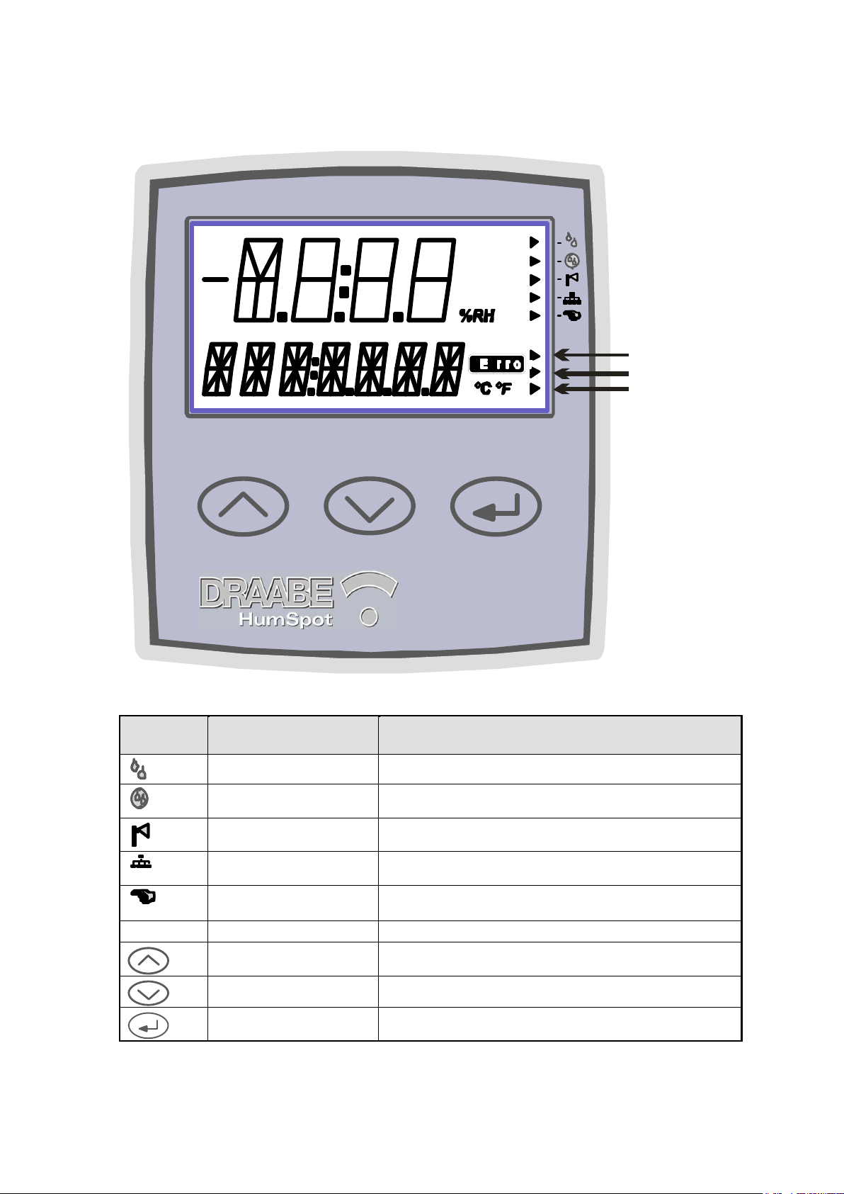
1 HumSpot
H u m i d it y & T e m p e r a t u r e
1
2
3
Symbol Function
Description
Humidification request
The internal hygrostat function or the external hygrostat is
requesting humidification
AFWS request
The automatic fresh water system is requesting
humidification
Atomiser active
The solenoid valves for the atomiser are open.
BUS active
HumiPur is being addressed via the BUS. i.e. there is a
connection to CenterPur.
Manual operation
The hygrostat has been manually overridden.
If "" is set to “no”, this symbol will flash
1 – 3
Mean value
Shows mean value of calculation across 16, 60 and 180 min
Function keys
Select menu points and enter values
Function keys
Call up menu points and enter values
Enter key
Call up menu and confirm values.
Created: 04.06.2007 3
Changed: 21.12.2007
Printed: 02.03.2009
Page 4
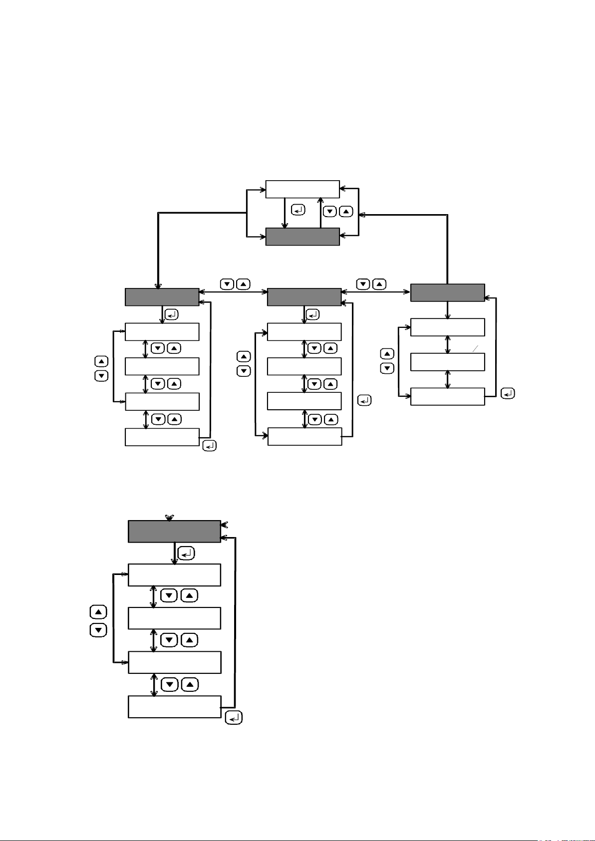
The menu mode can be called up using the enter key. The separate menu
standard parameter
*FOG
target %RH
SETPT
Hysteresis
HYST
exit submenu
EXIT
display controls
*DISP
backlighting.
BGL ON
units °C / °F
UNIT T
if keylocked:
CODE?
LCD display
LCD OUT
Measur. mode
activation
LOCK
exit submenu
EXIT
set code
CODE
keylock code
*KEYLO
exit submenu
EXIT
ACTIVE
INACTIVE
Standby function for
FOGING
2 sec.
Falls
Code = 0
std parameterr
*FOG
target %RH
SETPT
Hysteresis
HYS
T
exit submenu
EXIT
Standby function for
FOGGING
points can be called up with the arrow keys. Each menu has an “EXIT” point
to return to the next higher menu.
If the key lock is enabled, the code must be entered first to access the menu.
The entire menu level is shown in the illustration below. In the following, the
separate menus will be described in greater detail.
1.1 FOG menu
In the FOG menu, the following settings can be made:
Created: 04.06.2007 4
Changed: 21.12.2007
Printed: 02.03.2009
Page 5
Menu
Parameter
Range
FOG
Humidity target
10 – 90 % RH
Steps of 1%,
default: 50%
FOG
Hysteresis
0.5 – 10.0% RH
Steps of 0.1% RH
Default 2% RH
FOG
Fogging
Auto, no
Default: "Auto"
Menu
Parameter
Range
DISP
Backlighting
(BGL)
00:05 – 10:00
[mm:ss]
Steps of 1 s
Default: 1 min
DISP
LCD display
Auto, On
Default: Auto
DISP
Temperature
unit
°C, °F
Default: °C
display controls
*DISP
backlighting
BGL ON
units °C / °F
UNIT T
LCD display
LCD OUT
exit submenu
EXIT
1.2 DISP menu
Created: 04.06.2007 5
Changed: 21.12.2007
Printed: 02.03.2009
Page 6
1.3 KEYLO menu
Menu
Parameter
Range
KEYLO
Code
0000 – 9999
Default: 0000
KEYLO
Activate code
activation
LOCK
exit submenu
EXIT
set code
CODE
keylock code
*KEYLO
Falls
Code = 0
Created: 04.06.2007 6
Changed: 21.12.2007
Printed: 02.03.2009
Page 7
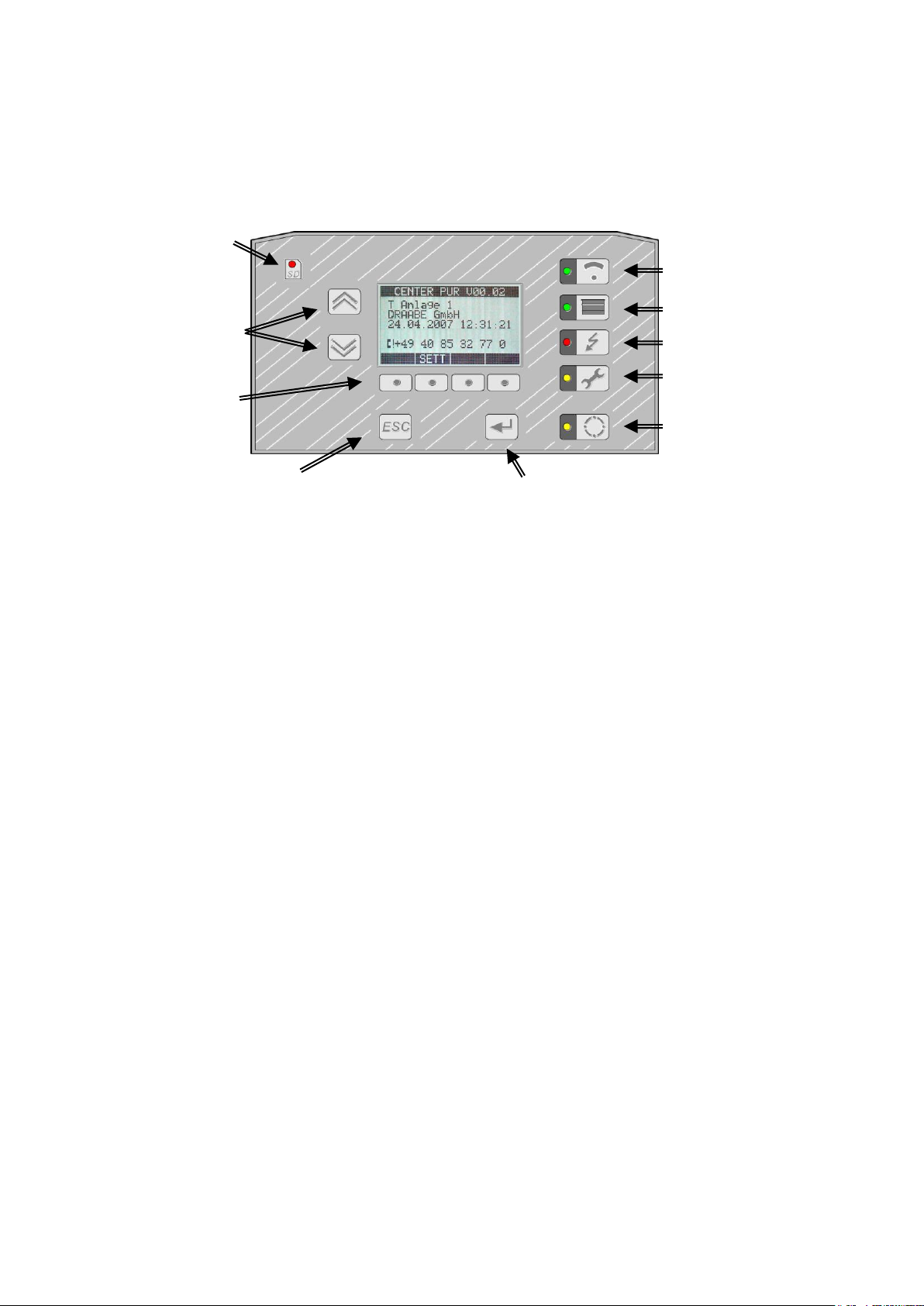
2 HumCenter
„UP/DOWN
key
for “select”
& “scrolling”
LED
memory
access
indicator
“SD Card
“ESC” (back)
function key
„ENTER“
function key
Fixed- value
function keys:
Zones 1–24
(overview / detail)
Containers 1–5
(overview / detail)
Alarm action
(current/list of 60 items)
Head office &
Service
(settings)
Multi-select key
4 x function
softkeys
The HumCenter has several function keys and a display. The separate
function keys are explained below.
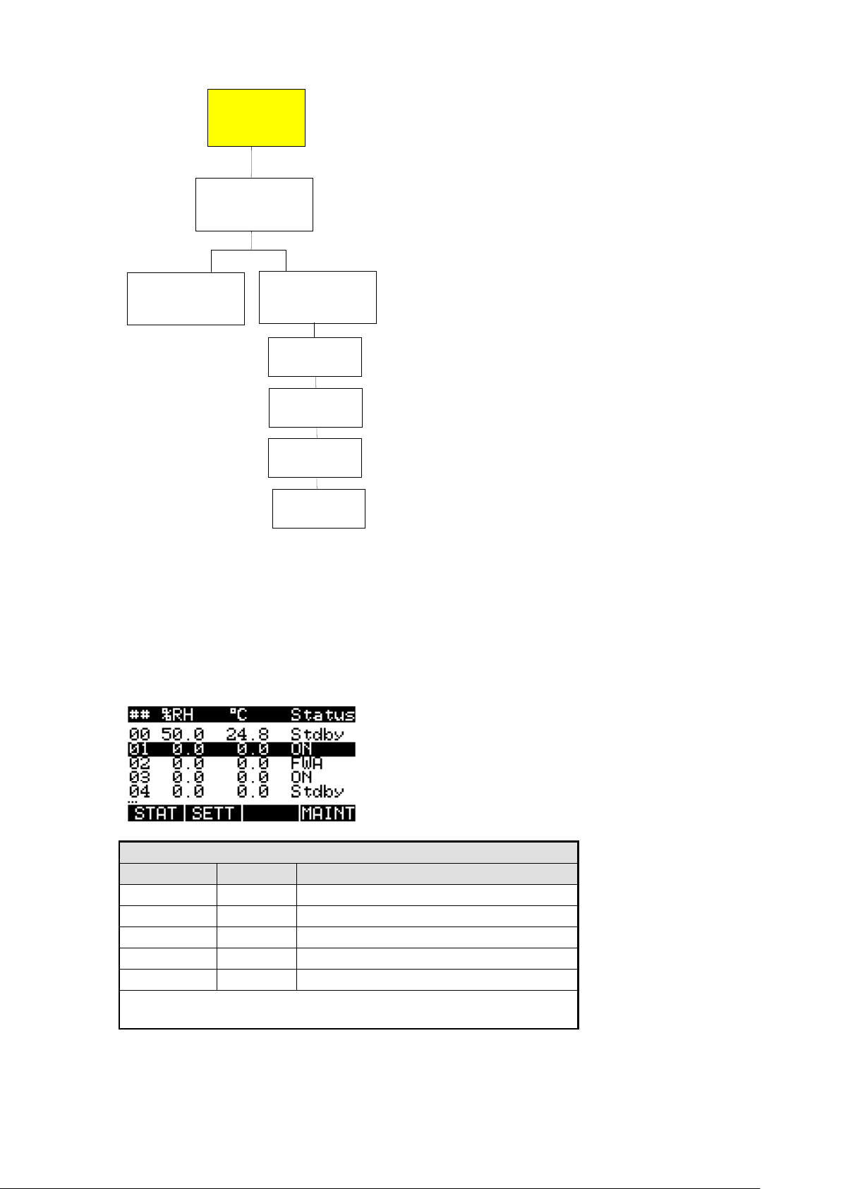
2.1 Zone menu
The zone overview is displayed by pressing the “Zone” function key. The
display shows the first five zones. For every zone, the display indicates the
zone number, the current relative humidity and temperature and a simplified
status report. Select a zone or see more zones using the “UP”/”DOWN keys.
Created: 04.06.2007 7
Changed: 21.12.2007
Printed: 02.03.2009
Page 8
Simplified status
Display
Priority*
Description
ERR
1
Error
ON 2 Humidification or request active
AFWS
3
Automatic fresh water system active
OFF
4
Fogging = No
Stby
5
Humidification off, no request
* When two status reports occur at once, that with lower priority is
shown.
Zones
1–24
Overview of
Zones & status
Details
for a zone
Settings
for a zone
"STAT"
"SETT"
Set point
[% RH]
Hysteresis
[% RH]
Fogging
[ No/AUTO ]
CODE
[ xxxx ]
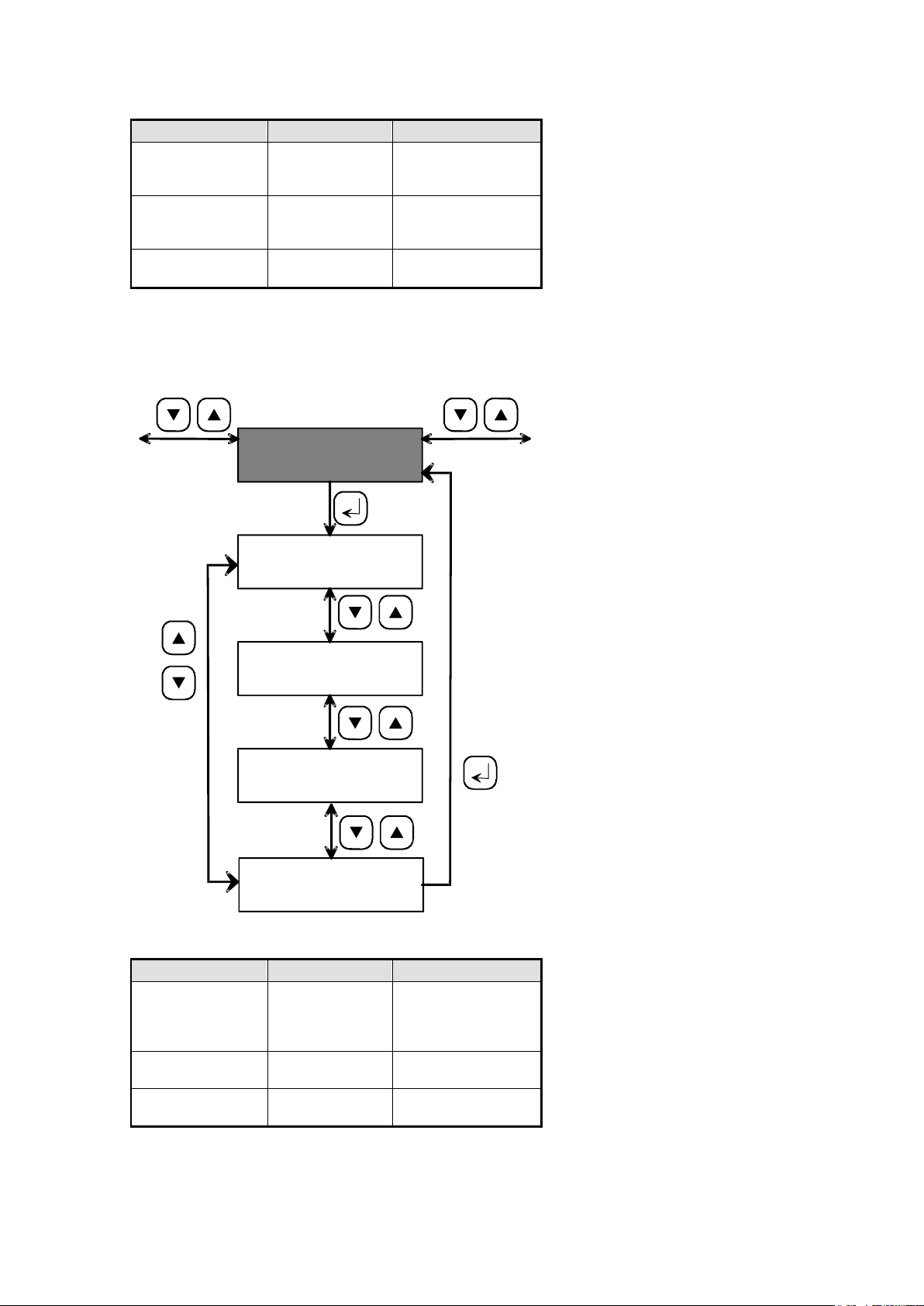
2.1.1 Zone overview menu
Created: 04.06.2007 8
Changed: 21.12.2007
Printed: 02.03.2009
Page 9
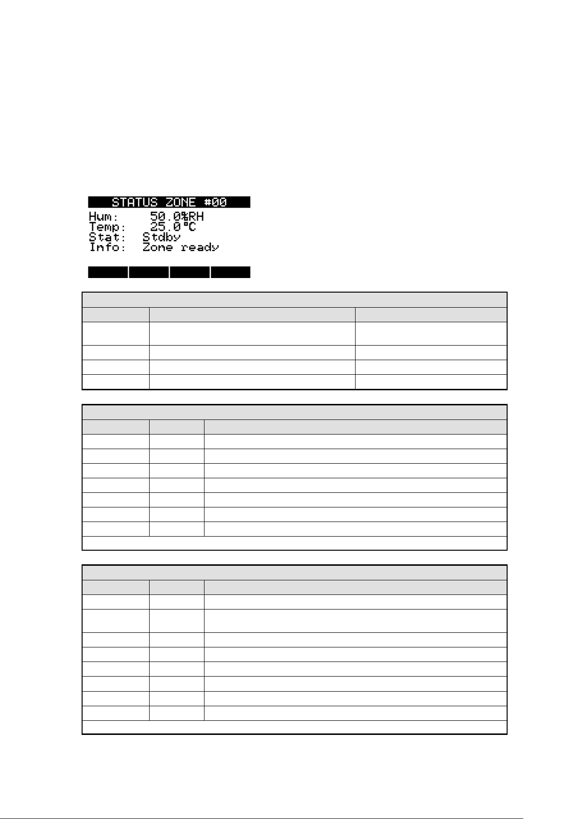
The advanced status display (STAT) or the settings (SETT) for the selected
Parameter
Name
Function
Notes
Hum:
Current humidity [% RH], sensor resolution 0.1 %
RH
Temp:
current temperature [°C] or [°F], resolution 0.1 °C
Stat:
Summary of status
Info:
Additional status information
Status
Display
Priority*
Description
ERR
1
Error
Hand
2
Manual operation on
Humid
3
Humidification active
FWA
4
AFWS active
H req
5
Humidification request
AFWS req
6
AFWS request
Stdby
7
Standby (e.g. target value reached)
* When two status reports occur at once, that with lower priority is shown.
Info
Display
Priority*
Description
Com err
1
Communication error with HumiPur
Cap err
2
Capability error: HumiPur cannot fulfil the function required.
Causes: Firmware not updated, device technology outdated
no HPS
3
No HPS entered.
Sens err
4
Communication with sensor disturbed (e.g. sensor malfunction)
Max err
5
Maximum hygrostat released
HPS err
6
HPS not released (timeout)
Unkn err
7
Unknown error
Zone Ready
8
Zone ready for operation
* When two status reports occur at once, that with lower priority is shown.
zone can be selected using the softkeys below the display.
2.1.2 Status menu (STAT)
The status menu shows the status in detail. As well as the relative humidity,
temperature and the status there is also additional information on the zone.
This shows whether the zone is ready for operation (zone ready) or which
problem has occurred in case of malfunction.
Created: 04.06.2007 9
Changed: 21.12.2007
Printed: 02.03.2009
Page 10

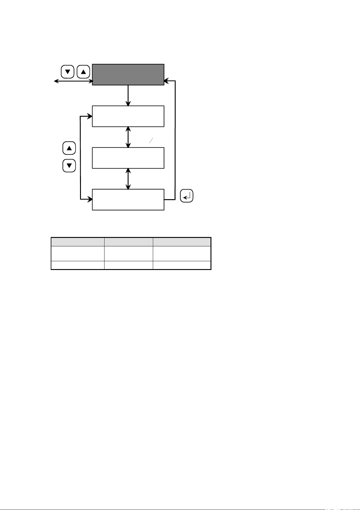
Return to the overview using the ESC key.
Parameter
Name
Function
Notes
SETPT:
Humidity target [% RH]
10 – 90 % RH
Steps of 1%,
Default: 50%
HYST:
Hysteresis [% RH]
0.5 –10.0% RH
Steps of 0.1% RH
Default 2% RH
FOGGING:
Fogging parameters
Auto, no
Default: "Auto"
CODE:
Keylock code
0000 – 9999
Default: 0000
2.1.3 Settings menu (SETT)
The settings menu shows the following settings for the selected zone:
Select and change the settings using the UP/DOWN keys. After selection,
then click on the “SET” softkey to change the value.
Move the cursor with the arrow keys and set the value with the + and - keys.
Use the ENTER key to confirm and save the new value. Undo the change with
the ESC key.
Created: 04.06.2007 10
Changed: 21.12.2007
Printed: 02.03.2009
Page 11

2.2 Water supply menu
Containers
1–5
Overview of
containers 1–5
Details
for a container
"STAT"
Container
type
Container
serial no.
Container
status
Container
information
Container
conductivity [μS]
Container
P. pressure
Container
flow rate
ALL
ALL
ALL
ALL
SYN/
PER
3200
Only
3200
Only
3200
Press the “water supply” function key to display an overview of the units
attached to the HumCenter and their current status.
Created: 04.06.2007 11
Changed: 21.12.2007
Printed: 02.03.2009
Page 12

2.2.1 Water supply overview
Simplified status for CSF 3121 (PER)
Display
Priority*
Description
ERR
1
Error
FULL
2
Tank full
ON
3
In operation
* When two status reports occur at once, that with lower priority is shown.
Simplified status for CSF 3200 (PER)
Display
Priority*
Description
ERR
1
Error
FULL
2
Tank full
ON
3
In operation
* When two status reports occur at once, that with lower priority is shown.
Simplified status for LS 3400 (SYN)
Display
Priority*
Description
ERR
1
Error
Mntc
2
Maintenance
FWA
3
Circulation
ON
4
In operation
* When two status reports occur at once, that with lower priority is shown.
Simplified status for HPS 3200 (HIG)
Display
Priority*
Description
ERR
1
Error
ON
2
Pump running
Stby
3
No malfunction, pump off
* When two status reports occur at once, that with lower priority is shown.
# TYPE STATUS d
1 HIG ON
2 HIG Stby
3 SYN ERR
4 PER ON
STAT MAINT
Created: 04.06.2007 12
Changed: 21.12.2007
Printed: 02.03.2009
Page 13

2.2.2 Status menu
Parameters for CSF3121 (PER)
Name
Function
Notes
Dtype:
Device type
CSF3121 (M261,M262, M263, D250)
DNum:
Device number
(D250,D251)
Stat:
Summary of status
See table below
Info:
Additional status information
See table below
Status of CSF3121 (PER)
Display
Priority*
Description
ERR
1
Error (M201, M236, M250, M251), com error
Full
2
Tank full (M235)
ON
3
In operation
* When two status reports occur at once, that with lower priority is shown.
Info on CSF3121 (PER)
Display
Priority*
Description
Com err
1
Communication error
Cap err
2
Capability error: CSF cannot fulfil the function required.
Causes: Firmware not updated, device technology outdated
Safety press. err
3
Safety pressure error (M201)
Inlet press. err
5
Inlet pressure error (M236)
Conductivity err
6
Conductivity error (M250)
Motor prot. err
4
Motor protection error (M251)
PerPur ready
7
PER ready for operation
* When two status reports occur at once, that with lower priority is shown.
Select a unit with the UP/DOWN keys and display the detailed status with the
“STAT” softkey.
## STATUS HIG #1 d
Dtype: HPS3200
DNum: 4294967296
Stat: ON
Info: HighPur ready
Created: 04.06.2007 13
Changed: 21.12.2007
Printed: 02.03.2009
Page 14

Parameters for CSF3200 (PER)
Name
Function
Notes
Dtype:
Device type
CSF3200 (M261,M262, M263,
D250)
DNum:
Device number
(D251,D252)
Con:
Conductivity
µS (D240)
Press:
Pump pressure
bar (D239)
Flow rate:
Flow rate
L/h (D238)
Stat:
Summary of status
See table below
Info:
Additional status information
See table below
Status of CSF3200 (PER)
Display
Priority*
Description
ERR
1
Error (M200, M201, M204, M236, M237, M253), com error
Full
2
Tank full (M239)
ON
3
In operation
* When two status reports occur at once, that with lower priority is shown.
Info on CSF3200 (PER)
Display
Priority*
Description
Com err
1
Communication error
Cap err M
2
Capability error: CenterPur cannot fulfil the function required.
Causes: Firmware not updated, device technology outdated
Cap err D
3
Capability error: PER cannot fulfil the function required.
Causes: Firmware not updated, device technology outdated
Safety press. err
7
Safety pressure error (M201)
Inlet press. err
8
Inlet pressure error (M200)
Conductivity err
3
Conductivity error (M236)
Motor prot. err
6
Motor protection error (M253)
Pump press. err
5
Pump pressure error (M237)
Mntc pump
9
Pump maintenance (M204)
PerPur ready
10
PER ready for operation
* When two status reports occur at once, that with lower priority is shown.
Parameters for LS3400 (SYN)
Name
Function
Notes
Dtype:
Device type
LS3400 (M261,M262, M263,
D250)
DNum:
Device number
(D251,D252)
Con:
Conductivity
µS (D248)
Stat:
Summary of status
See table below
Info:
Additional status information
See table below
Created: 04.06.2007 14
Changed: 21.12.2007
Printed: 02.03.2009
Page 15

Status for LS3400 (SYN)
Display
Priority*
Description
ERR
1
Error (M200–M205), com error
Mntc
2
Maintenance (M234)
FWA
3
Circulation (M235)
ON
4
In operation
* When two status reports occur at once, that with lower priority is shown.
Info on LS3400 (SYN)
Display
Priority*
Description
Com err
1
Communication error
Cap err M
2
Capability error: CenterPur cannot fulfil the function required.
Causes: Firmware not updated, device technology outdated
Cap err D
3
Capability error: LS cannot fulfil the function required.
Causes: Firmware not updated, device technology outdated
Safety press. err
7
Safety pressure error (M200)
Inlet press. err
9
Inlet pressure error (M201)
Gas press. err
8
Gas pressure error (M202)
Motor prot. err
6
Motor protection error (M203)
Synthesis err
5
Synthesis error (M204)
Product err
4
Product error (M205)
Mntc Syn
10
Maintenance (M234)
SynPur ready
11
PER ready for operation
* When two status reports occur at once, that with lower priority is shown.
Parameters for HPS 3200 (HIG)
Name
Function
Notes
Dtype:
Device type
HPS3200 (M261, M262, M263, D250)
DNum:
Device number
(D250,D251)
Stat:
Summary of status
See table below
Info:
Additional status information
See table below
Status for HPS 3200 (HIG)
Display
Priority*
Description
ERR
1
Error (M200–M204), com error
ON
2
Pump running (M232)
Stdby
3
No malfunction, pump off
* When two status reports occur at once, that with lower priority is shown.
Created: 04.06.2007 15
Changed: 21.12.2007
Printed: 02.03.2009
Page 16

Info for HPS 3200 (HIG)
Display
Priorit
y*
Description
Com err
1
Communication error
Cap err M
2
Capability error: CenterPur cannot fulfil the function required.
Causes: Firmware not updated, device technology outdated
Cap err D
3
Capability error: HIG cannot fulfil the function required.
Causes: Firmware not updated, device technology outdated
Motor prot. err
6
Motor protection switch (M204)
Leakage err
4
Leakage error (M201)
Min. press. err
5
Minimum pressure error (M200)
Inlet press. err
8
Inlet pressure error (M202)
Temp. err
7
Temperature error (M203)
HighPur ready
9
Container ready for operation
* When two status reports occur at once, that with lower priority is shown.
Alarms
Pend/Hyst.
Current
"pending"
ALARMS
"Pend"
"LOG"
History
"old"
ALARMS
Detailed
ALARM
information
Detailed
ALARM
information
"DET"
"DET"
select line
Delete
"LOG" ALARMS
[only old]
"CLR"
2.3 Alarms menu
Press the “Alarms” function key to display the “Alarms” overview menu. In this
menu you can switch between the two menu levels “Pending” and “Log”.
Created: 04.06.2007 16
Changed: 21.12.2007
Printed: 02.03.2009
Page 17

2.3.1 Pending alarms menu
In the “Pending” menu, all current pending alarm reports are shown. For
further details
2.3.2 Alarm log menu
In the “Log” menu, all past alarm reports are shown.
Created: 04.06.2007 17
Changed: 21.12.2007
Printed: 02.03.2009
Page 18

2.4 HumCenter menu
Parameter
Line
Parameter
Notes
1
VXX.XX
Version of the CenterPur software
2
Installation:
Display of unit
3
Operator:
Name of customer
4
Date & time:
Current time
6:
Service phone:
Number in case of malfunction
HumCenter
Overview
Hum
Center
Detail
User settings
Hum
Center
"SETT"
Clock
[TT:DD:MM:YY]
UNIT
[°C / °F]
LCD
[ 1....9]
LOG
[hh:mm]
User
[ XXXX ]
LOCK
[ Set ]
Press the “HumCenter” function key to display the HumCenter overview
menu.
2.4.1 HumCenter overview
Created: 04.06.2007 18
Changed: 21.12.2007
Printed: 02.03.2009
Page 19

Further settings can be made using the “SETT” softkey.
Parameter
Name
Function
Notes
Clock setting...
Submenu to set the clock
Unit temperature:
Temperature unit (only CenterPur)
°C or °F
LCD contrast:
Display contrast
LOG Int:
Interval for logger [hh:mm]
Interval for data logger
Load Configuration
Load configurations from SD card
Save Configuration
Save configurations on SD card
Reboot System
Reboot HumCenter
Code:
CenterPur code
Lock...:
Activate code immediately
2.4.2 HumCenter settings
Created: 04.06.2007 19
Changed: 21.12.2007
Printed: 02.03.2009
Page 20

3 HumCenter software update
The HumCenter software can be updated very simply using the SD card. The
current software is sent by e-mail, copied onto the SD card and then installed
on the HumCenter.
Carry out the following steps:
1. Remove the SD card from the HumCenter and connect it to a
computer.
2. Enclosed in the e-mail are the files “boot.sys” and “flash.bin”.
3. Copy these files and save them on the SD card.
Created: 04.06.2007 20
Changed: 21.12.2007
Printed: 02.03.2009
Page 21

4. Re-insert the SD card in the HumCenter.
5. Select the “HumCenter” menu.
6. Press the “SETT” key and select "Reboot system".
HumCenter V1.06 d
Save Configuration
Load Configuration
Reboot System mmm
Code: ****
SETT
7. Confirm the request with “yes” and keep the “HumCenter” key pressed
during the reboot until “Flash Programmer” appears in the display. The
new software is now automatically updated.
After the installation, restart the HumCenter. All previous settings are retained.
Created: 04.06.2007 21
Changed: 21.12.2007
Printed: 02.03.2009
Page 22

3.1 BMS link
Identifier
Parameter
Format
BACnet
Option
Objects
Notes
A
Date/time
U8;U8;U16;U8;U8;U8
(DD;MM;YYYY;HH;MM;SS)
Example:
A07;11;2007;11;45;15
AI 201
Time
telegram
sent
B
Zone alarms
U32
Bit0=Zone1, Bit1=Zone2 etc.
Examples:
B0 = no alarm
B1 = zone 1 alarm
B3 = zone 1 and zone 2 alarm
BI 1-24
Objects are true
if faulted.
Example if BI...
1=1 Zone 1 fault
4=0 Zone 4 ok
7=1 Zone 7 fault
C
Container alarms
U8
Bit0=Container1 etc.
Examples:
C0 = no alarm
C1 = container 1 alarm
BI 101-105
Objects are true
if faulted.
Example if BI...
101=1 Ctn 1 fault
104=0 Ctn 4 ok
105=1 Ctn 5 fault
D
Current zone
values
Float, Float
(HH.H;TT.T)
Example:
D1:39.5;23.8
AI 1-24 Humidity
AI 101-124 Temp
AI 1=39.5 is
39.5%rh
AI 101=23.8 is
23.8°C
HH.H in
[%RH]
TT.T in
[°C]
Z
CRC
U16
The HumCenter has an interface to link to the building services management
system. The HumCenter is designed so that the parameters to be transferred
are converted to the bus system using an external converter (e.g. RS232
Ethernet converter).
The converter is connected at the RS232 interface on the top of the
HumCenter next to the SD card slot. The maximum cable length between the
HumCenter and the converter is 3m.
3.1.1 Parameters
The following parameters are transferred:
- Date/time
- Zone alarms
- Container alarms
- Current zone values (humidity, temperature)
Each parameter is labelled in the telegram using identifiers:
Created: 04.06.2007 22
Changed: 21.12.2007
Printed: 02.03.2009
Page 23

The parameters transferred can only be read; it is not possible to change the
Symbol
Description
Notes
*
Start symbol
Start of telegram
A – Z
Identifier
Identifies the parameter
:
Index
Index in case of array data (D:1)
;
Data separator
Separates the data (D:1; 25.0; 50.0 – “;”
separates the data from the index and
the temperature from the humidity)
.
Decimal point
CR+LF
End of line
Lines of telegram finish with a “carriage
return” and “line feed”.
settings via the BMS.
3.1.2 Telegram
Every five seconds, the HumCenter sends a telegram with the parameters
described above. The following is an explanation of the symbols used in the
telegram and the telegram layout, using an example.
The following symbols are used in the telegram:
Layout of a sample telegram with the following configuration:
- 3 zones (HumSpots)
- 2 containers
Telegram:
*A07;11;2007;11;29;04;B0C2D:1;43.3;24.8;D:2;42.5;23.3;D3:40.8;20.1Z3221
9
The telegram contains the following information:
- Date/time: 07.11.2007, 11:29:04 (A07;11;2007;11;29;04)
- Zone alarms: No alarm (B0)
- Container alarms: Container 2 alarm (C2)
- Zone 1 values: Humidity: 43.3 % rH, temp.: 24.8 °C
(D:1;43.3;24.8)
- Zone 2 values: Humidity: 42.5 % rH, temp.: 23.3 °C
(D:1;42.5;23.3)
Created: 04.06.2007 23
Changed: 21.12.2007
Printed: 02.03.2009
Page 24

- Zone 3 values: Humidity: 40.8 % rH, temp.: 20.1 °C
(D:1;40.8;20.1)
- Checksum: 32219 (Z32219)
3.1.3 Transfer parameters
19,200 bit/s
Data bits: 8
Stop bit: 1
Parity: none
Flow control: none
3.1.4 CRC checksum
It is not usually necessary to calculate and evaluate the checksum.
If desired, it can be calculated as follows:
Up to and including the “Z” identifier, the function “crc_one_byte()” is
accessed for every figure in the telegram, with "*oldchecksum” initialised to 0
at the start of the telegram.
Algorithm
/* calculate 16-Bit CRC */
/* At start of calculation *oldchecksumP must be */
/* initialised to 0 */
/* oldchecksumP (IO): pointer on (previous) checksum*/
/* b: next byte of data stream */
void crc_one_byte(u16 *oldchecksumP, unsigned char b)
{
u16 result;
unsigned char a=b ^ (*oldchecksumP)>>8 ^ (*oldchecksumP)>>4 ^ (*oldchecksumP)>>1
^ (*oldchecksumP)<<1;
result = (*oldchecksumP)<<8 | a ^ a>>7;
*oldchecksumP = result;
}
Created: 04.06.2007 24
Changed: 21.12.2007
Printed: 02.03.2009
Page 25

3.1.5 BACnet Option connection
The BACnet Gateway is a small device that attaches to the HumCenter’s
serial communication port. This is done by connecting the two with a serial
cable with a DB9 female to DB9 male connection. This is a straight cable, pin
1 to 1, 2 to 2 ... 9 to 9. The Gateway is then connected to the BACnet
network with an Ethernet Cable. It must also be supplied with power
(120V/1P)
DB9 Cable connection
Ethernet Connection
BACnet Gateway general specification:
• Powered by 9 to 30VDC @ 0.37A to 0.11A
• 120VAC power supply included (12VDC output)
• FCC Class A, CE Mark
• Operating temperature -40°C to +85°C; Humidity 5% to 90%
Created: 04.06.2007 25
Changed: 21.12.2007
Printed: 02.03.2009
Page 26

4 Troubleshooting
Error message
Possible causes
Possible solutions
BUS ERR
1. The HumCenter is switched off.
2. Bus communication error (wiring
error) between HumSpot and
HumCenter
3. No bus ID or wrong bus ID entered in
HumSpot.
4. Bus ID assigned to a unit without
HumCenter.
1. Check the electricity supply to
the HumCenter.
2. Check the bus connection at
HumSpot and HumCenter.
3. Check the bus ID at HumSpot.
4. Set the bus ID to 0.
CAP ERR
1. Capability error: HumSpot does not
have current firmware.
2.
1. Install the current firmware in the
HumSpot.
2.
No HPS
1. No HPS has been assigned to the
HumSpot
2.
1. Assign an HPS to the HumSpot
using the HumCenter.
2.
SENS ERR
1. Hygrostat malfunction.
1. Replace the sensor.
MAX ERR
1. Maximum hygrostat has triggered
due to high room humidity.
2.
1. Check maximum hygrostat is
functioning.
2. Check hygrostat is functioning.
3. Adjust target value of maximum
hygrostat.
HPS ERR
1. No release received from HPS
(timeout).
1. Check if the HPS is
malfunctioning.
2. Check the wiring between the
HumSpot and HPS.
4.1 HumSpot
Created: 04.06.2007 26
Changed: 21.12.2007
Printed: 02.03.2009
Page 27

4.2 HumCenter
Error message
Possible causes
Possible solutions
COM ERR
(Zone)
1. The HumSpot is switched off.
2. Bus communication error (wiring
error) between HumSpot and
HumCenter
3. No bus ID or wrong bus ID entered in
HumSpot.
4. Bus ID assigned to a unit without
HumCenter.
1. Check the electricity supply to
the HumSpot.
2. Check the bus connection at
HumSpot and HumCenter.
3. Check the bus ID at HumSpot.
4. Set the bus ID to 0.
No HPS
1. No HPS has been assigned to the
HumSpot
1. Assign an HPS to the HumSpot
using the HumCenter.
SENS ERR
1. Hygrostat malfunction.
1. Replace the sensor.
MAX ERR
1. Maximum hygrostat alert has set off
due to high room humidity.
2.
1. Check maximum hygrostat is
functioning.
2. Check hygrostat is functioning.
3. Adjust target value of maximum
hygrostat.
HPS ERR
1. No release received from HPS
(timeout).
1. Check if the HPS is
malfunctioning.
2. Check the wiring between the
HumSpot and HPS.
Error message
Possible causes
Possible solutions
COM ERR
(Water Supply)
1. Unit is switched off.
2. Bus communication error (wiring
error) between unit and HumCenter
1. Check the electricity supply to
the unit.
2. Check the bus connection at the
unit and the HumCenter.
CAP ERR M
1. Capability error: The HumCenter
does not have current firmware.
1. Install the current firmware in the
HumCenter.
Zone:
Water supply
Created: 04.06.2007 27
Changed: 21.12.2007
Printed: 02.03.2009
Page 28

Manufacturer:
DRAABE Industrietechnik GmbH
Schnackenburgallee 18
D-22525 Hamburg
+49 40 853277-0
www.DRAABE.de
A WMH company
Distributer:
Nortec Systems Inc.
1860 Renasissance Blvd.
Sturtevant, WI 53177
262.884.4669
www.nortecsytems.us
Created: 04.06.2007 28
Changed: 21.12.2007
Printed: 02.03.2009
 Loading...