

Page 1
Important: Read and save these instructions. This guide to be left with equipment.
1502247-E | 18 JUL 2011
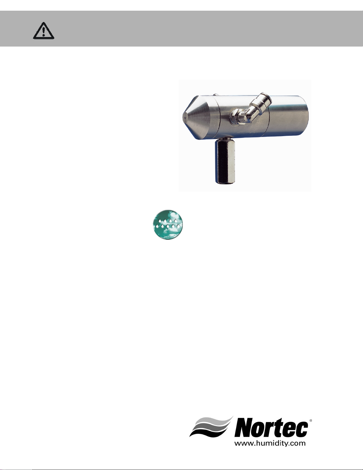
AIRFOG
Series
Installation and
Operation Manual
Includes installation, operation
maintenance and troubleshooting
information for your AirFog Series
Atomizing humidifier
Page 2

Thank you for choosing NORTEC.
INSTALLATION DATE (MM/DD/YYYY)
MODEL #
SERIAL #
Proprietary Notice
This document and the information disclosed herein are proprietary data of WALTER MEIER LTD. Neither this
document nor the information contained herein shall be reproduced used, or disclosed to others without the
written authorization of WALTER MEIER LTD., except to the extent required for installation or maintenance of
recipient’s equipment. All references to the NORTEC name should be taken as referring to WALTER MEIER LTD.
Liability Notice
NORTEC does not accept any liability for installations of humidity equipment installed by unqualified personnel
or the use of parts/components/equipment that are not authorized or approved by NORTEC.
Copyright Notice
Copyright 2011, WALTER MEIER LTD. All rights reserved.
Page 3

Contents
1 Introduction
1 AirFog Humidifiers
1 AirFog Family of Products
1 AFE Principle of Operation
2 General AirFog Technical
Considerations
5 Installation
5 Nozzle System Layout
7 Zones
7 Introduction
7 Supply Feed Lines
7 Cleaning
7 Mounting of Nozzles
9 Connecting Nozzles
9 Saddle Clamp Installation
11 Vacuum Valve
11 Pilot Operated Air Regualtor
15 Primary Air Pressure Control
15 Primary Water Pressure Control
15 Control Panel
15 Electrical Wiring
18 Pilot Lines
19 AFE Self Contained AirFog
Systems
19 AFE Mini Systems
21 AFE Octo Systems
26 AFE, Mini, and Octo Start-
up Procedures
26 Introduction
26 Compressed Air Supply
26 Water Supply
27 Self Cleaning Cycle Adjustment
28 Setting the System for Normal
Operation
30 AFE, Mini, Octo Shut Down
Procedures
31 Maintenance
31 Seasonal Maintenance
31 Seasonal Startup
32 Unscheduled Maintenance
32 Vacuum Valve Testing
32 Checking For Vacuum
Leaks
34 Troubleshooting
35 Replacement Parts
35 Repair Kits
36 Spare Parts / Exploded
Views
21 Installation Procedure
Page 4

Page 5

Introduction
Note: Prior to installing any AirFog product carefully READ through this entire guide, it
contains valuable information, which will assist in all aspects of the installation.
Applicability
This document is applicable to all Nortec AirFog system components purchased after February
2004. If the designer has existing system components purchased prior to February 2004, the
Nortec Technical Service Department should be consulted to determine compatibility with the
newer equipment, parts and external interfaces.
AirFog Humidifiers
Nortec AirFog systems use the nozzle humidification technology of injecting droplets of cold
water directly into the air. This method of humidification has the following advantages over
steam humidification:
Lower frequency of maintenance.
Systems are mainly mechanical (water pipes and air pressure) with only a 24 VAV power
requirement in the control panel.
A “no cost” air cooling benefit due to latent heat of vaporization extracting heat from the air.
Maintenance is primarily focused on keeping the air compressor operational.
Change of components is fast and requires minimal system disassembly.
AirFog Family of Products
The AirFog family is Nortec most advanced adiabatic humidifiers. There are groups of products
that fall in this family: applied products and packaged products.
The applied products group describes systems that are tailored specifically for each application:
AFE Nozzle systems use compressed subsonic air flows and water to create a fine mist that
is sprayed directly into a space.
The packaged products group describes systems that are ready to operate out of the box, and
need only be connected to power, air, and water. These products include:
AFE Mini: Systems are wall mounted and have 1 or 2 AFE nozzles.
AFE Octo: Systems are ceiling mounted and available in many configurations including
modulating versions, and have between 3 and 8 AFE nozzles.
This manual describes the installation, operation, and maintenance of all AFE, Mini and Octo
systems.
AFE Principle of Operation
The AFE nozzle uses air flow and the Bernoulli principle to siphon water out of zero psig
AirFog Installation Manual | 1
Page 6

water distribution pipes. Increases in air velocity (by increasing air pressure) will increase the
vacuum pressure and increase the rate that water is siphoned into the nozzle. As the water
exits the nozzle it is broken down into a fine mist by a shearing action created by the
compressed air. Increases in air supply pressure also means that the exiting mixed flow is at
a higher velocity.
Since AFE nozzle systems use a zero psig water pressure feed network, the water feed
system and nozzles at the same height as the water pressure reduction regulator (vacuum
valve). Valleys or peaks in altitude will adversely affect performance and in some cases will
prevent the nozzles from producing any output. If obstructions prevent straight level piping,
the water and air network delivery pipes must be routed under the obstruction. It is vital that
the water pipes, downstream of the vacuum valve, never be elevated higher than the
nozzles.
General AirFog Technical Considerations
Adiabatic Cooling Phenomena
There are no heating elements in any of Nortec’s AirFog humidifiers. Water is injected directly
into the air at the temperature it is supplied. As the droplets evaporate they extract sensible
from the surrounding air at a rate of approximately 1,000 BTU per pound of water evaporated.
This causes the temperature of the air to decrease, meaning that both humidity and cooling are
provided simultaneously. This could be a significant energy saving technique if mechanical
cooling is required. Since humidification is most often required when the exterior atmospheric
temperature is below room temperature, there is a necessity to warm the air either prior to
addition of the water droplets or after absorption of the droplets into the air. It is recommended
to add the moisture after the air is heated as this dramatically reduces the time and distance
taken for the water droplets to evaporate.
Humidification Zones (In Space Applications)
The movement of humidity through a space is very rapid. In applications where accurate
humidity control is essential, it is important that the structure be reasonably air-tight, well
insulated, and have good vapor barriers, to prevent humidity from escaping to the outside. If a
large amount of infiltration or exfiltration is encountered it may be necessary to oversize the
system to compensate for this.
AFE systems are frequently used in large factory applications for dust and static suppression.
Often these structures have large doors open for loading and unloading of goods. Keeping
doors closed, except when needed for movement of goods, can improve the performance of the
humidification system by containing humidity levels within the space.
Absorption Distance
Water mist sprayed by the AFE nozzle requires a certain distance to be absorbed by the air.
Absorption distance is affected by many factors including temperature, existing humidity levels
and air pressure. However, in general increasing the air pressure (and hence the water flow) to
the nozzle will increase the absorption distance since more water is being sprayed. It is
important to follow the clearances in this guide to prevent the accidental wetting of structures
or machinery.
2 | AirFog Installation Manual
Page 7

Compressed Air
Nortec AirFog systems use compressed air as the control fluid. Compressed air is provided by a
compressor (supplied by others) or series of compressors. The modular approach to the Nortec
AirFog systems permits the designer to consider the cost implications of using multiple smaller
horsepower compressors rather than one very large compressor. By using a multiple
compressor design solution, system reliability is increased, maintenance is possible without
shutting down all zones, and capital cost is often reduced.
It is recommended that air free of oil and moisture (control quality air) be used with AirFog
systems. All air compressors will produce moisture, which must be removed using a
refrigerated air dryer. Excessive amounts of water in the air lines will reduce nozzle
performance, and in extreme cases will prevent the nozzle from producing any mist. Oil must
also be removed from the compressed air through the use of oil removal filters.
Air pressure loss can be managed by reduction in the air pipe length, elimination of
unnecessary elbows, valves and flow restrictions, increasing the diameter of the primary
delivery pipe to the zones and elimination of leaks.
Water Quality
AirFog AFE nozzles are controlled from 316 stainless steel and can be used with potable,
reverse osmosis, and deionized water types. Potable water contains dissolved minerals that will
precipitate out of the water in the form of dust as the water evaporates. These minerals are
usually not harmful to the occupants of a space or to presses such as woodworking , printing,
paper, storage facilities, etc., however, clean area applications such as computer rooms,
electronics manufacturing, laboratories, paint, or fired finish areas may be adversely affected
by mineral dusting. In these cases Nortec recommends the use of reverse osmosis or
deionization systems to reduce the mineral content of the water before it enters the humidifier.
If you have questions regarding the suitability of the water for your application, please contact
the design engineer or your local Nortec representative.
Installation Tools and Equipment
The designer should have already provided drawings of the proposed AirFog humidification
system physical layout. These drawings and parts list should clearly identify the system
components by name and part number, physical spacing, zone identification and comments on
nozzle location and pointing directions.
During installation there will be a requirement to:
Attach mounting brackets to walls, ceilings or other structures, which may be higher than six
feet off the floor.
Cut and join copper, stainless steel or plastic pipe using standard plumbing joining
techniques.
Connect low voltage wiring to the control panel.
Connect plastic tubing.
The installer should have all the tools and be certified to perform these plumbing, mounting
and electrical tasks.
AirFog Installation Manual | 3
Page 8

Parts
A parts list should be included with the drawings developed by the designer. Not all the
necessary parts are provided by Nortec. The following parts are supplied by others:
Pipe, elbows, pipe hanger and mounting hardware for inside HVAC units, T-joints, pipe size
adapters, Teflon sealing tape and other plumbing supplies from a local plumbing supplier.
Pipe material is either copper, stainless steel or plastic and should be specified on the
designer produced drawings.
Wire for the electrical connections is 18 gauge standard insulation, which can carry 24 Volts
AC at 1 amp. This wire can be purchased from most electrical suppliers.
Nails, screws, bolts, threaded rods, anchors, rivets etc. to attach mounting brackets to the
structure. The fasteners used will depend on the material used in the mounting surface.
Insulation for the cold water pipe feeding the system is required to prevent water vapor from
condensing and dripping on other structures, machines, personnel or materials.
The Nortec supplied parts should be checked against the designer’s drawings and parts list
to ensure the correct quantity of the correct part numbers are available.
4 | AirFog Installation Manual
Page 9
Installation
Nozzle System Layout
If a drawing for the proposed system was not supplied, then it is recommended that one be
created prior to installing the system. With reference to the AirFog Engineering Manual, review
the site where the nozzle system is to be installed. The location of equipment, lights, pillars and
other structures should be drawn on the floor plans. The proper selection and location of the
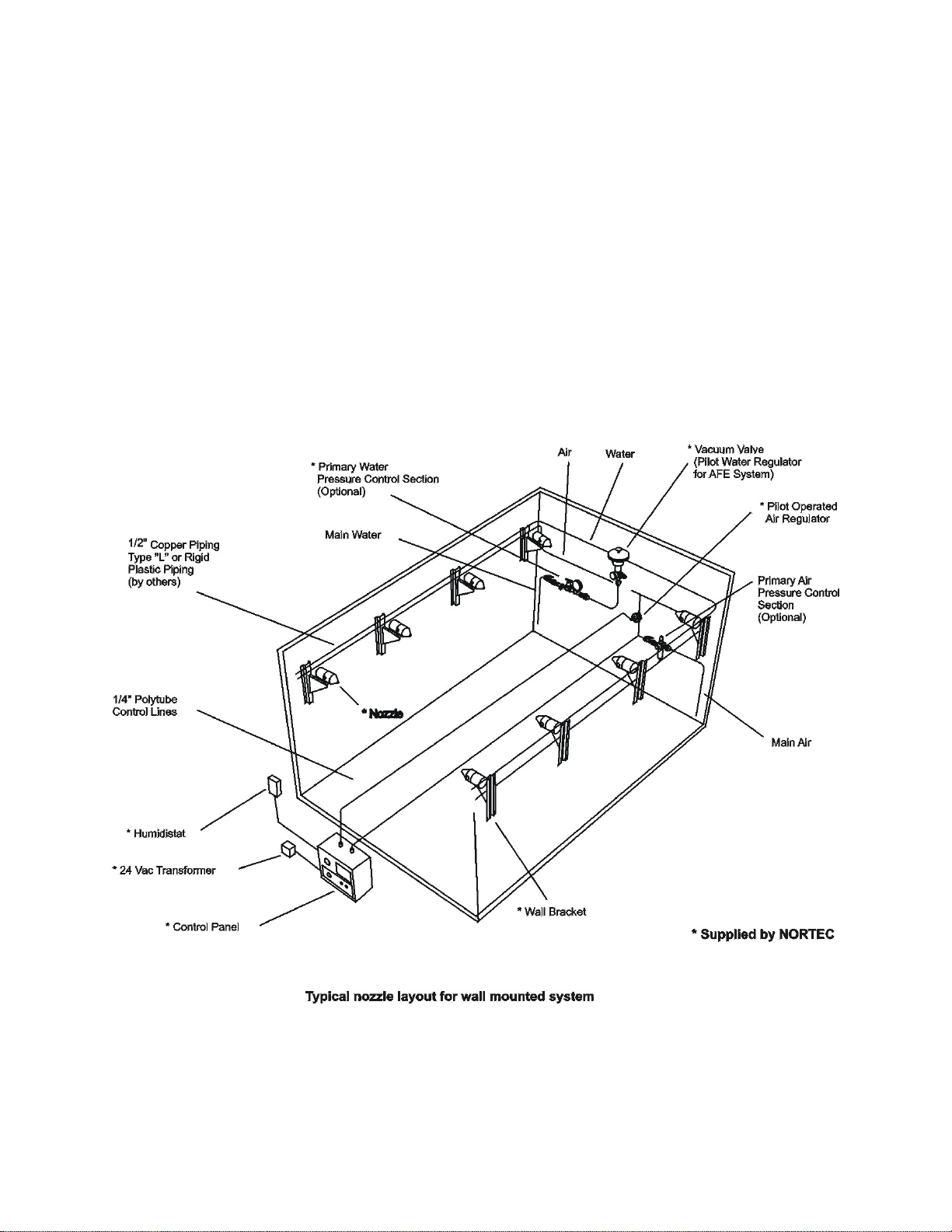
nozzles is very dependent upon these obstructions. Figure 1: Typical Nozzle Layout, can be
used as a guide for identifying the various components used with a system.
The supply and feed lines for the system should be kept in straight unobstructed lines where
possible. Air and water distribution network pipes are to be installed level along walls, pillars or
hung from the ceiling. Avoid placing the lines over top of equipment and other areas, which will
make it difficult to gain access at a later date. If the lines have to be routed around an obstacle
such as a beam, always go under the obstacle, never over it.
Figure 1: Typical Nozzle Layout for Wall Mounted System
AirFog Installation Manual | 5
Page 10
Install as close to control
panel as possible.
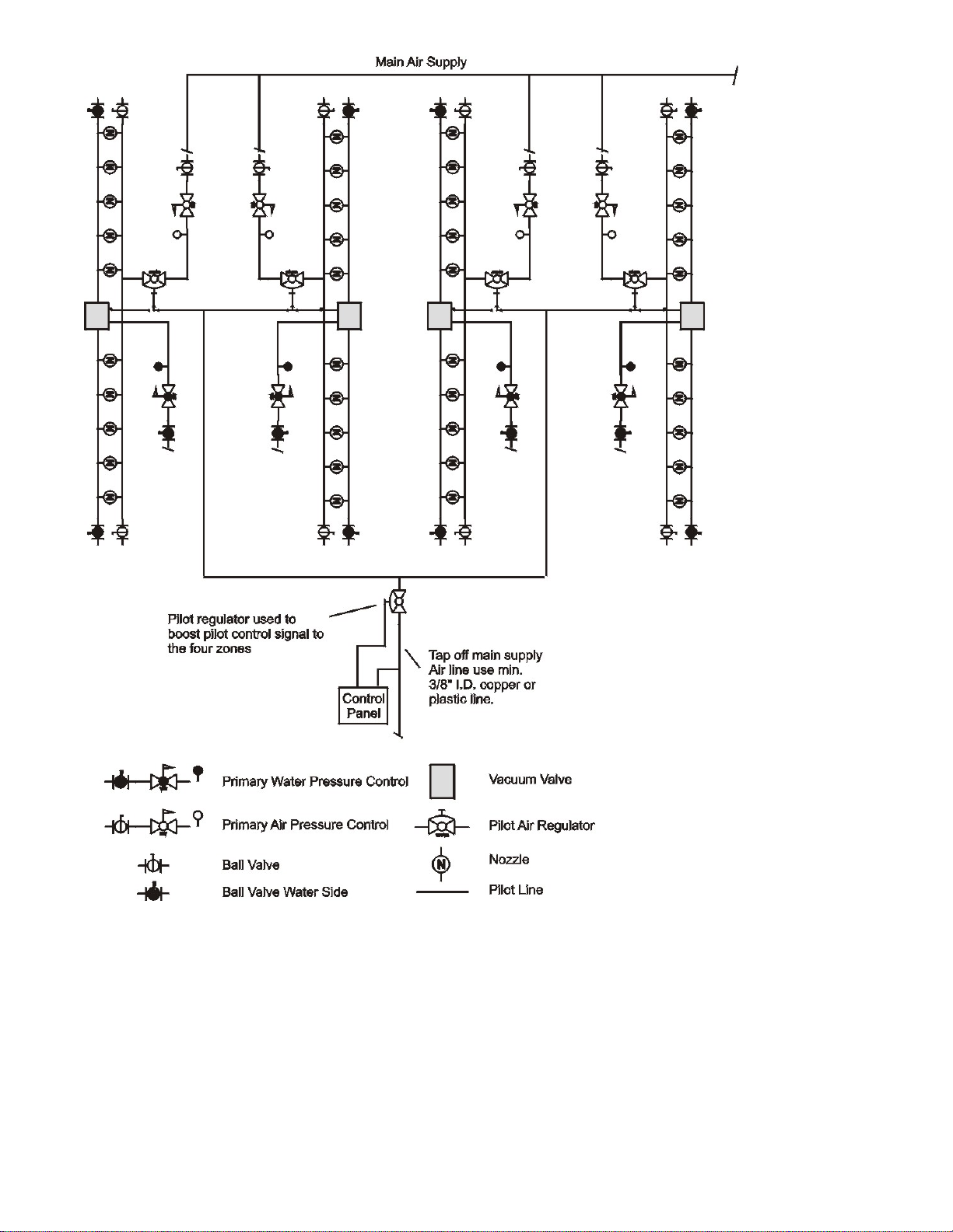
Figure 2: Multi Zone Layout
6 | AirFog Installation Manual
Page 11

Zones
Introduction
It may be necessary to break down the space to be humidified into zones. Limitation of the
control devices and maximum run of feed piping may indicate the need for multiple zones.
Refer to the Engineering manual for detailed limitation of components. Up to four zones can be
controlled from one control panel, additional zones can be added with the use of a pilot air
regulator acting as a volume booster for the pilot signal. See Figure 2: Multiple Zone Layout.
Supply Feed Lines
Main supply lines connecting to the system must be sized to handle system flow volumes and
pressures. Connections to each zone should have an isolation valve installed by using a
NORTEC supplied primary pressure control section as illustrated in Figure 3: Water and Air Line
Pressure Control. Primary air pressure feed to each zone should not exceed 90 psig. Water
feed pressure is not to exceed 25 psig for AFE, Mini and Octo hardware. Supply water pressure
is not to exceed 65 psig for AFD systems.
Both water and air lines must be installed as per the mechanical drawings using standard
plumbing joining techniques. The spans must not be greater than 5 feet without a supporting
bracket. For long runs of piping, expansion joints may be needed and these joints must meet
local building codes. When using Nortec supplied saddle clamps, the maximum line size for
supplying to nozzles is 11/16” O.D. If saddle clamps by others are used, please size fittings to
match the pipe.
Cleaning
Manual valves must be installed at the ends of all lines to facilitate cleaning and drainage of
lines. Cleaning is done by temporarily connecting the pipes to a compressed air source at one
end of the pipe. The other end of the pipe must not be connected to any equipment but be free
to allow the egress of foreign matter. Care must be taken to protect personnel, animals,
machines or other sensitive material from the potentially hazardous and contaminating matter,
which will exit at high speed from the opening.
Note: Cleaning of the lines of all foreign material prior to connecting any system component
is critical, failure to maintain clean lines may void the warranty.
A.
Mounting of Nozzles
Each supplied Nortec nozzle has a 3/8” NC 16 threaded port on the under side of the nozzle
which is used to fasten the nozzle to a mounting bracket, as illustrated in Figure 4: Nozzle To
Bracket Interface or Figure 5: AFE Nozzle Ceiling Mounting. If other than NORTEC supplied
mounting hardware is to be used, ensure correct bolt and thread size is used. Nozzles can be
mounted in any elevation angle as water throughput capacity is not affected by this orientation.
However, AFE nozzle capacity is sensitive to vertical height differences to the vacuum valve.
The maximum nozzle installation height allowable above the water supply line is 12” (30 cm).
AirFog Installation Manual | 7
Page 12

A
Primary Air Pressure Control Section
Primary Water Pressure Control Section
Figure 3: Water and Air Line Pressure Control
Lag Bolts
Mounting Holes
For 1/4" Lag Bolts
Saddle
Clamp
Polytube
(Supplied By Others)
Saddle Clamp
Polytube
FE Nozzle
Wall Support Bracket
Figure 4: Nozzle to Bracket Interface
8 | AirFog Installation Manual
Page 13
t
Threaded Rod
(Supplie d B y O th er s)
Nozzle Support
Bracket
Water Line
Air Line
Installation Hardware Package
(Includes Saddle Clamps,
Adapters And Tubing.)
AFE Nozzle
Supply Lines
To Nozzles
(By Others)
Pipe Hanger
(By Others)
Figure 5: AFE Nozzle Ceiling Mounting
Connecting Nozzles
All the supplied nozzles have two inlet ports with push in, quick release style fittings as shown in
Figure 6: Quick Release Fittings. These fittings are only designed for use with 1/4” O.D. plastic
tubing. If other than Nortec supplied tubing is to be used, it must be a high grade uniform
tubing from a reputable supplier.
The Nortec supplied fitting uses an o-ring to seal the O.D. of the tubing and finger clamps to
hold it in place. Failure to use proper size tubing may result in poor sealing and cause system
failure. The tubing MUST be cut square using a knife or plastic tube cutter rather than pliers.
To connect the tube to the nozzle simply push the tubing into the nozzle fitting until it reaches
the bottom. Gentle pulling of the tube without movement is a good indication that a proper seal
has been made.
Allow enough free tubing to permit the nozzle to swivel horizontally or vertically for future
pointing alignment.
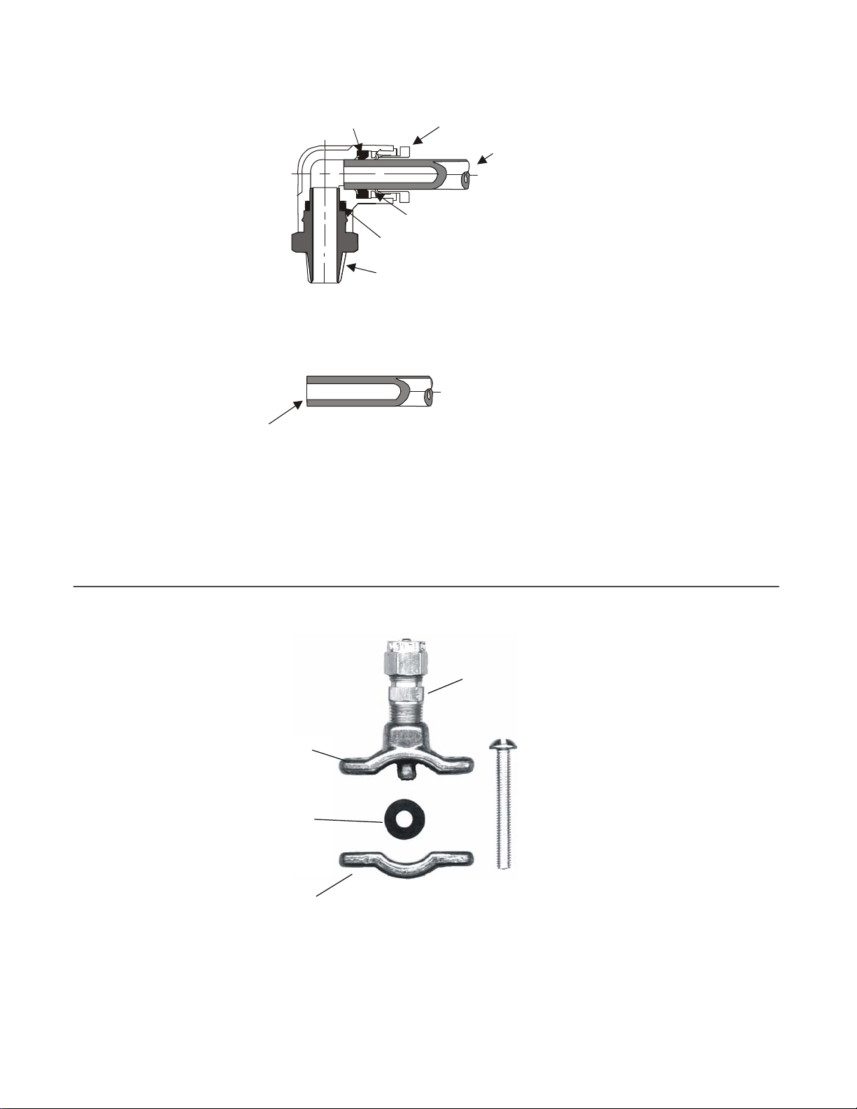
Saddle Clamp Installation
The type of clamp used by Nortec, as shown in Figure 7: Saddle Clamp, requires that the pipe
be drilled first. Drill a 1/4” hole squarely into the air and water pipes close to each nozzle
within 24” (60 cm). Place the sealing gasket on the male part of clamp, insert it into the drilled
hole, then clamp it into place using the provided screws. The saddle clamp has a 1/8” FNPT
port; install either the supplied compression fitting or another style fitting suitable for plastic
ubing. Two saddle clamps, one for air and one for water, are required for each nozzle.
Note: Not to be used with DI water. For DI water use stainless steel tee.
AirFog Installation Manual | 9
Page 14
Cut-away View of Quick
Disconnect Fitting
Seal
O-Ring Seal
NPT Threads
1/4" Tubing
Tubing MUST be cut
to ensure proper seal. Use sharp knife,
not w ire cu tt e r s or p lie r s.
Locking Ring
1/4" Tubing
Locking Fingers
PERPENDICULAR
Figure 6: Quick Release Fitting
Fitting
Top
Clamp
Screw
Gasket
Bottom
Clamp
10 | AirFog Installation Manual
Figure 7: Saddle Clamp
Page 15

Vacuum Valve
The vacuum valve must be centrally located so there are approximately an equal number of
nozzles being fed from each of its two output ports (one on the left side and the other on the
right side). There is a mounting bracket supplied with each vacuum valve. Figure 9: Vacuum
Valve Interfaces illustrates the plumbing interface details. Elevation of the valve is very critical,
as is the positioning of the nozzles. The maximum height above the nozzle supply line the valve
should be installed is 12” (30 cm). Never install the vacuum valve lower than the nozzle water
feed lines.
The water flow rate through this valve is limited to 24 GPH, which limits the number of AFE
nozzles it can supply to 16. If more than 16 nozzles are to be installed, then the system must
be broken into zones using multiples of 16 (or less) nozzles with each zone controlled by its own
vacuum valve. One control panel can control multiple zones by “T” ing off the single control
panel air pilot output.
Air pressure from the control panel is used to open the water safety valve permitting water to
enter the vacuum valve, which controls the water feed to the nozzles. Figure 8: Vacuum Valve
Operation explains the operation of this water regulator. The vacuum valve assembly has three
sub-components. As illustrated in Figure 9: Vacuum Valve Interfaces. First, the safety valve
interfaces directly with the primary water supply to open or close on command from the control
panel. Loss of pilot air pressure (below 10 psig) will automatically close this valve to prevent
water proceeding beyond this point. In series with, and downstream of the safety valve, is the
water regulator. The water regulator is used as the first stage of water pressure reduction. The
water regulator reduces the supply water pressure to a range between 5 and 10 psig. This is
set manually at time of installation. Please note that system performance is not sensitive to the
exact setting as long as the pressure is within this range.
The second stage of water pressure reduction is the vacuum diaphragm, which drops the
pressure to ambient (0 psig). Output is through two exit ports on the underside of the vacuum
valve. This permits the nozzle to draw water from the supply as required rather than having
pressure force it into the nozzle. The siphoning action of the nozzle is controlled by the pilot
operated air regulator.
On top of the vacuum valve is a thumb wheel adjustment for adjustment of the AirFog droplet
size. The adjustment changes the volume of water to the nozzles. A reduction in available
water for a constant air flow results in smaller droplets and a finer spray. This adjustment can
be used to reduce the water throughput if there is a problem with water droplets reaching the
floor.
Pilot Operated Air Regulator
The pilot operated air regulator controls the air supply to the nozzles and is illustrated in Figure
10: Pilot Air Regulator. The pilot regulator is modulating flow controller rather than a simple
On/Off valve. The greater the pilot air pressure, the greater the air pressure fed to the nozzle
supply network. This means that the Control Panel is able to request a proportional opening of
the Air Regulator simply by varying the pilot pressure. There is a linear 1:1 relationship between
the pilot pressure and the output pressure drop. A pilot air pressure of 25 psig (172.5 kPa) will
drive the air regulator to have an output of 25 psig (172.5 kPa). A pilot pressure of 50 psig will
drive the air regulator to have an output of 50 psig. The pilot air pressure range is from 0 to 70
psig.
AirFog Installation Manual | 11
Page 16

The four ports on the pilot operated air regulator are the pilot air pressure input from the control
panel, the primary air supply input feed, the output air feed to the nozzles and to gauge port
used to feed pilot signal to the water regulator. There are no manual adjustments required.
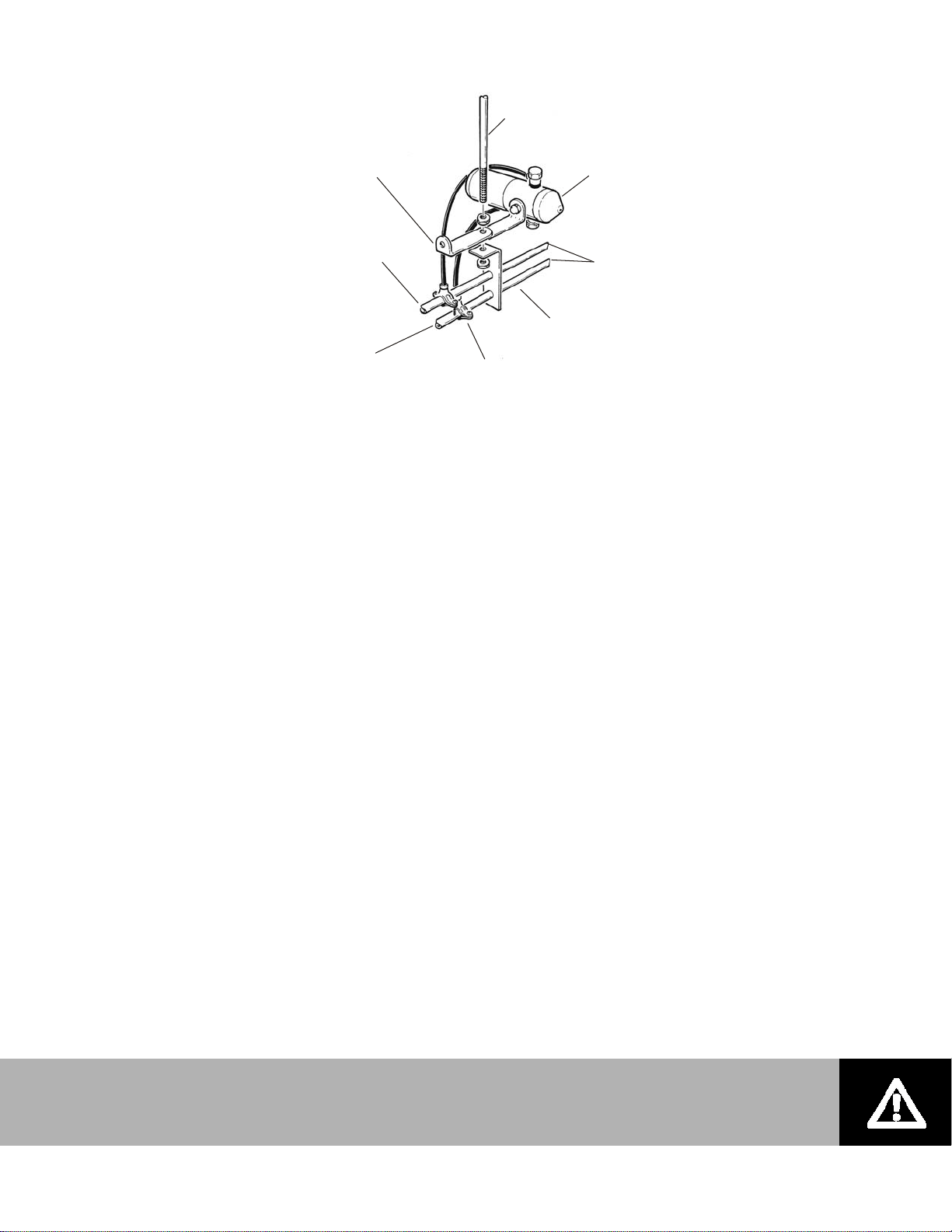
Install the pilot air regulator on the feed line before the nozzles by splicing into the air feed line
to the nozzles. See Figure 11: Pilot Air Regulator Installation. Ensure the proper flow direction
when installing this device.
12 | AirFog Installation Manual
Page 17

A
ir Compressor
A
A
Compressed air exits the nozzles
creating a vacuum on the water
side. The negative pressure pulls
the VV diaphragm down, opening
the water valve.
Water
ir Compressor
s the pressurised water enters the
VV chamber it pushes up on the
diaphram closing the water valve.
Dur ing no rmal operati o n the
vacuum valve will cycle between
the open and closed state.
Water
Figure 8: Vacuum Valve Operation
Figure 9: Vacuum Valve Interfaces
AirFog Installation Manual | 13
Page 18

Outlet Port
Pilot Operated
Air Regulator
Inlet Port
Pilot Line from Control Panel
Figure 10: Pilot Air Regulator
Feed Line to Nozzles
Figure 11: Pilot Air Regulator Installation
14 | AirFog Installation Manual
Page 19

Primary Air Pressure Control
The primary air pressure control section (with the shutoff valve) is connected to the air
compressor or the compressed air source as specified in the Designer produced drawings. See
Figure 12: Primary Air Pressure Control Section.
Primary Water Pressure Control
The primary water pressure control section connects the main water supply. The shutoff valve
end of section is the inlet. The gauge end of the section is joined to the water inlet of the
vacuum valve for AFE systems. See Figure 13: Primary Water Pressure Control Section.
Control Panel
Bolt the panel directly to the surface through the mounting holes. Place the panel level against
the surface and mark locations for holes to be drilled. Remove the panel and drill 2 holes (hole
size to match field supplied lag bolts and anchors). Place panel over the holes and secure it
using bolts.
Electrical Wiring
Electrical connections of the control panel use 18 ga wire for all external wiring. The control
panel requires 24 VAC, which is provided by the Nortec supplied step down transformer (120
VAC to 24 VAC). The transformer plugs into any standard 120 VAC outlet that must be located
within 6’ (six feet) of the control panel. Power is connected to the low voltage terminal trip
located inside the panel as illustrated in Figure 16: Control Panel Terminal Strip Interfaces.
Control panels are supplied by Nortec in two configurations. The first is for use with systems
that are designed to operate with only an On/Off humidistat and the second is designed to
operate with a modulation controller. Within the control panel there is a 7 point terminal block,
terminals 6 & 7 are for power voltage 24 VAC. A wiring diagram is provided with each control
panel. Both control panels reserve terminals 1 & 2 are for on/ off control wiring which may be a
simple humidistat, a relay for remote operation or other interlock devices (dry make break
contacts).
Modulation controlled systems use terminal 3, 4 & 5 on the 7 terminal block strip as follows:
terminal 3 is to be connected to the “+” terminal on the controller, terminal 4 is to be connected
to the “-“ terminal on the controller and terminal 5 is for 24 VAC supply to the controller. This is
illustrated in Figure 15: Control Panel Terminal Strip Interfaces.
AirFog Installation Manual | 15
Page 20

1/2" FNPT
1/4 Turn Shut Off Valve
1/2" NPT Brass Union
Air Regulator
1/2" N PT
Brass Union
Filter ( opt ional)
Figure 12: Primary Air Pressure Control Section
Shut Off Valve
1/2" NPT
Brass Uni on
Pressure Gauge
0-100 PSIG
1/2" NPT
1/2" FNP T
Brass "Y " Type
Strai ner 1/2" NPT
Brass Union
1/2" FNPT
Figure 13: Primary Water Pressure Control Section
16 | AirFog Installation Manual
Page 21

Pilot Outlet
Pilo t Inlet
(Main Air)
Pilot
Pressure
Gauge
Lock
Pressure
Regulator
Yellow
Light
Humidifing
Green
Light
on/off
Figure 14: Control Panel
On/Off
Switch
Control
Wiring
Input
76
24 VAC
5
Optional
24 VAC
+
-
Modulation
Input
Figure 15: Control Panel Terminal Strip Interfaces
On/Off
Controls
1234
AirFog Installation Manual | 17
Page 22

Pilot Lines
All air pressure lines connecting to the control panel must be 1/4” O.D. plastic tubing rated for
150 psig. Figure 16: Schematic Plumbing Layout illustrates the proper connections of the air
supply to and from the control panel to the vacuum valve and the pilot air regulator. The control
panel requires an input pneumatic (air) control supply, which is usually tapped off the main air
supply line upstream of the pilot air regulator. The control panel has two pneumatic fittings
located on its top plate; one marked “pilot in” and the other marked “pilot out”. The “pilot in” is
connected to the control supply with the 1/4” plastic tubing. A second 1/4” line connects the
“pilot out” to both the pilot air regulator and the vacuum valve using a “T” connector.
Single Zone Configuration
Primary Water Pressure Control
Primary Air Pressure Control
Ball Valve
Ball Valve Water Side
Figure 16: Schematic Plumbing Layout
Pilot Air Regulator
Nozzle
Pilot Line
Control
Panel
18 | AirFog Installation Manual
Page 23

AFE Self Contained AirFog systems
AFE Mini Systems
AFE MINI systems are self-contained packaged systems that include all necessary components.
They require the following connections:
3/8” O.D. plastic or soft copper water supply line rated at a minimum of 25 psig.
1/4” O.D. plastic or soft copper air supply line rated at a minimum of 90 psig
Isolation valves for both air and water lines
Mounting hardware
Support anchors
1/4” lag bolts
120 VAC standard electrical receptacle
Humidity control device (Humidistat)
The best location for a MINI is on a wall or column with the mist discharging down an aisle
where it will not condense on solid surfaces. A clear run of at least 15 feet forward of the
nozzles is normally a sufficient distance for complete absorption. Adiabatic cooling may be
uncomfortable to people occupying workstations directly beneath the Mini systems.
The Mini nozzles must be a minimum of 6 feet above the floor and 36” below the ceiling in
order to prevent condensation on these surfaces.
Four accessible internal mounting holes are located in each corner of the rear panel. The
mounting procedure is:
Either attach the supplied mounting bracket hardware or bolt panel directly onto the wall
surface via the mounting holes.
Place the panel level against the surface and mark the drill holes.
Remove the panel and drill the holes (hole size to match field supplied lag bolts and
anchors).
Replace the panel and secure using bolts.
Install water and air supply lines. Both water and air lines should have an isolation valve
installed near the unit. Water connection at the unit is designed for 3/8” plastic tubing but if
soft copper pipe is to be used, replace the plastic sleeve in the fitting with the supplied brass
sleeve. The air connection is designed for 1/4” plastic tubing.
AirFog Installation Manual | 19
Page 24

3 ft (1 m) minimum
15 ft (4. 5 m) clearance
each nozzle
6 ft (1.8 m) minimum
Figure 17: Control Panel
20 | AirFog Installation Manual
Figure 18: AirFog Mini Connections
Page 25

AFE Octo Systems
Octo systems are partially self contained and are between the simple Mini self-contained
installation and the modular AFE systems. The Designer’s drawings and parts list will define the
configuration. The only installation difference between the full modular system and the Octo is
that the vacuum valve and pilot air regulator are located inside the Octo case as illustrated in
Figure 19: Octo Layout and Interfaces.
The Octo interfaces are:
3/8” O.D. plastic or soft copper water supply line rated at a minimum pressure of 25 psig
½” O.D. plastic or soft copper air supply line rated at a minimum pressure of 90 psig
1/4” O.D. plastic tubing for command air pressure (pilot air)
Isolation valves for both air and water lines
Hanging hardware
Chains
Threaded rod
Support anchors
AFE Control panel
120 VAC standard electrical receptacle
Humidity control device (Humidistat)
Installation Procedure
Octo units are designed to be suspended from the ceiling by either a threaded rod or chains.
Octos with nozzles on only one side may also be mounted on a wall or pillar (single sided
configurations). Prior to mounting, ensure there are no obstacles such as duct work, lighting,
large equipment, etc., Please refer to Figure 20: Octo Spray Pattern for further information. The
Octo unit should be installed as high as possible above the floor, any equipment or work space.
Adiabatic cooling maybe uncomfortable to people occupying workstations directly beneath the
Octo systems. The recommended height above the floor is 20 ft (6.1 m) and 18” below ceiling
joists.
When using chains to suspend the Octo, ensure the chains are rated for the units weight (64
lbs) and that all local building codes are followed.
In general:
Each Octo weighs up to 64 lbs (29 kg).
Install the four 3/8” NC eye bolts into the four mounting holes on the unit using the supplied
lock washers & nuts.
Install field supplied supporting chains or rods from the ceiling then raise the unit up into
location and secure in place.
Note: Always hang units, never use a cradle assembly, which can interfere with spray
pattern or restrict access for service.
AirFog Installation Manual | 21
Page 26

Figure 19: Octo Layout with Interfaces
22 | AirFog Installation Manual
Figure 20: Octo Spray Pattern
Page 27

Mounting using threaded rods requires installing field supplied 3/8” NC supporting rods
from the ceiling, raising the unit up into location and securing it to the support rods using
the supplied washers and nuts.
Both water and air lines should have an isolation valve installed near the unit as
illustrated in Figure 23: Octo Air And Water Interfaces. Water connection at the unit is
designed for 3/8” plastic tubing; however, if soft copper pipe is to be used, replace the
plastic sleeve in the fitting with the supplied brass sleeve. Air connection is designed for
½” plastic tubing. If soft copper pipe is to be used, replace the plastic sleeve in the
fitting with the supplied brass sleeve.
For a standard Octo unit, a separate control panel and 1/4” O.D. plastic tubing for pilot
line is required. To install this line the fitting on the unit is a push in style located above
the main air connection. Simply cut the tubing square and push one end into the fitting.
Route the line back to control panel location.
If multiple Octo units are to be controlled from a single control panel then “T” off the pilot
air pressure line to connect the other OCTO units as illustrated in Figure 23: Four Octo
Units With A Single Control Panel. If more than four Octo’s are to be controlled from one
control panel, use a pilot air regulator or a volume booster for the pilot line.
Octo Plus units do not require a separate control panel as there is one mounted within
the unit. All that is necessary is to connect it electrically as explained in this manual
under Electrical Wiring.
Control Panel installation for standard Octo hardware is explained in the under Control
Panel section.
The nozzles on the Octo units are pointed straight forward when shipped but these can
be oriented in any direction that will not have the plume strike a solid object or another
plume for at least 16 feet. Figure 24: AFE Octo Nozzle Spray Pattern helps in
visualization of these AIRFOG plumes.
AirFog Installation Manual | 23
Page 28

Figure 21: Ceiling Mounting of Octo
For copper tubing replace
Tube must exce ed end of slee ve
by a m in. 0.125" (3m m)
plastic sleeve with the supplied
brass s leev e
Plastic Tube
Locking Nut
Wate r connection
3/8" compression fitting
24 | AirFog Installation Manual
Bul khe ad Uni on on
pl um bing side
Pil ot in co nn ec t ion 1/4"
qui c k connect
Air connection 1/2"
compression fitting
Figure 22: Octo Air and Water Interfaces
Page 29

Figure 23: Four Octo Units with a Single Control Panel
Figure 24: AFE Octo Nozzle Spray Pattern
AirFog Installation Manual | 25
Page 30

AFE, Mini, and Octo Start-up Procedures
Introduction
The operator must make reference to Figure 1: Typical Nozzle Layout when following these
instructions. Prior to startup, ensure the following:
All components have been visually checked for proper connections.
All supply and feed lines have been cleaned.
The on/off valve of the primary water pressure control section is OFF.
Water at 25 psig pressure from the main supply is ON.
The on/off valve of the primary air pressure control section is OFF.
The air compressor is running and providing a minimum of 90 psig.
The control panel switch is OFF.
The 24 VAC transformer is plugged into a 110 VAC source and the green control panel power
indicator light is illuminated.
The humidistat is set at 100% relative humidity. (For startup & testing purposes only).
Adjust to desired setpoint after unit operation has been confirmed.
Compressed Air Supply
The clean out valves on the ends of the supply pipes must be closed.
The on/off valve of the primary air pressure control section is opened to the ON position. The
handle should be in line with the pipe (as opposed to 90 degrees to it).
The control panel switch is turned to the ON position.
Adjust the air pressure regulator in the control panel to about 70 psig to obtain maximum water
throughput for each nozzle for this startup test.
There should an audible hissing sound as the compressed air works its way through the piping
to the nozzles. If this is not detected and air cannot be felt by hand directly in front of the nozzle
orifice, then air is not being provided to the system. Check the compressed air line back to the
compressor for other valves that may not be open.
The air pressure regulator knob in the primary air pressure control section is to be adjusted until
its gauge indicates 90 psig.
Most significant air pressure leaks can be detected by sensing the air flow with the hand or by
spraying on soapy water to observe the growth of bubbles around the leak. If an AFE nozzle is
sucking some air rather than 100% water through the water pipes, the nozzles will sputter/spit
and behave irregularly as opposed to a steady production of uniform mist. A thorough survey
should be conducted to identify and fix leaking joints.
Water Supply
The clean out valves on the ends of the water supply pipes must be closed.
26 | AirFog Installation Manual
Page 31

The on/off valve of the primary water pressure control section is turned ON. The handle should
be in line with the pipe (as opposed to 90 degrees to it).
Adjust the water regulator valve in the primary water pressure control section until the gauge
reads 25 psig. The pressure regulator on the vacuum valve should be adjusted to read between
5 and 7 psig.
Manually depressing the thumb screw on top of the vacuum valve will permit water to flow into
the pipes and fill them.
AIRFOG water throughput can be controlled at the control panel by adjusting the air pressure.
This air pressure must never be greater than 75 psig. If water spray should reach the floor, then
the water throughput can be reduced by adjusting the air pressure, droplet size, or both as
described the following paragraph. Reducing the air pressure feed to the nozzles. Refer to
Figure 25: Capacity Output vs. Vacuum Valve Adjustment and Figure 26: AFE Capacity Chart.
Water flow through the nozzles can be adjusted using the thumb-wheel on the vacuum valve.
Turning the thumb-wheel clockwise will lower water flow through the valve, which will cause a
finer mist from the nozzles and a lower capacity. Turning the thumb-wheel counterclockwise will
raise the water flow through the valve, which will cause a coarser mist from the nozzles and
increased capacity. The optimal setting for the valve is a balance between capacity and spray
length. If the spray is reaching the floor or wetting equipment, try turning the thumb-wheel
clockwise. If the room is not receiving enough humidity, try turning the thumb-wheel counterclockwise. Some experimentation may be necessary to obtain the best results. Please refer to
Figure 1: Capacity Output vs. Vacuum Valve Adjustment for more information.
Self Cleaning Cycle Adjustment
The AFE, Mini, and Octo Systems all feature an automatic self-cleaning mechanism that
prevents mineral build-up in the nozzle tip. Buildup of lint, dust, or other materials on the
exterior of the nose cone can affect nozzle performance. Nozzles should be inspected and
cleaned periodically to remove any buildup. This mechanism activates whenever air pressure
falls below 10 psig. This will occur every time the humidistat cycles the nozzles off based on
demand, or when the unit is manually switched off. Additionally, a timer is included that allows
the user to set automatic cleaning cycles (off time), which occur after a period of operation.
The timer is a white box with several dials on the front of it. The timer can be removed (after the
unit has been powered off) for ease of adjustment; simply pull on the timer to remove it. To
adjust the timer:
The upper white dial and blue dial control the length of the time the system will remain on
for (T
For example, to have the unit remain on for 4 hours before powering off, turn the white dial
to point at 1-10h, and then turn the blue dial to point at 4.
The lower white and blue dials control the length of time the system will remain off for one
the timer cycles it off (T
example, to have the unit remain off for 2 minutes, set the white dial to 1-10min, and then
turn the blue dial to point at 2.
). The white dial is used to set the scale, and the blue dial is used to set the value.
on
). The white dial sets scale, and blue dial sets the value. For
off
If the timer were set as in the above examples, the system would run for 4 hours, shut off for 2
minutes, run for another 4 hours, shut off for 2 minutes, and so on and so forth.
Note: The humidistat takes precedence over the timer for shutting down the system. If the
humidistat reaches its set point, it will shut the system off regardless of the timer to
prevent over humidifying the space.
AirFog Installation Manual | 27
Page 32

The factory default setting for the timer is 2 minutes of off time (cleaning time) after every 8
hours of operation. Using settings that result in an off time of less than 10 seconds are not
recommended. As well, using settings that result in an on time of less than 15 minutes are not
recommended.
Setting the System for Normal Operation
Once the start-up and adjustment, and configuration procedures have been completed the unit
is ready to operate normally. The following steps complete the start-up procedures:
Close and lock all covers including the control panel covers.
Tighten the lock nuts on the primary air and water regulators.
Set the humidistat to the desired level.
The AirFog humidification system is now ready to operate normally.
28 | AirFog Installation Manual
Page 33

Figure 25: Capacity Output vs. Vacuum Valve Adjustment
Figure 26: AFE Capacity Chart
AirFog Installation Manual | 29
Page 34

AFE, Mini, and Octo Shut Down Procedures
Controlled system shutdowns are conducted for either maintenance (scheduled or repair) or
long term seasonal reasons. If the shutdown is for short term maintenance then it may be
possible to shorten this full procedure.
The following procedures are the recommended method to manually terminate AirFog
operations for long periods of time. Typically this would be after the heating season (winter) is
over.
Turn off the water supply valve on the primary water pressure control section
Allow the system to operate for 10 minutes to extract as much of the water as possible from
the water pipes.
Turn off the system and connect a hose to the clean out valves / hose bib. Direct the hose
to a bucket, open the valve, and allow the system to drain completely.
Disconnect the 24 VAC transformer from the 110 VAC supply.
Turn off the air supply valve on the primary air pressure control system.
Turn the system off at the control panel.
Turn the air compressor off.
For long periods (weeks or longer) of system down time, it is recommended that pressurized air
is used to blow all water out of the system.
It is important that components are not disconnected or removed from the system while they
are under pressure (air or water). Turning the master switch off in the control panel will isolate
all high pressure water system components downstream of the vacuum valve (AFE systems).
This control panel switch will also isolate all high pressure air system components downstream
of the pilot air regulator. This is often all that is required to isolate the nozzles. Be sure that the
air and water mains supplying the system will still be under pressure.
If there is any doubt about whether a component, pipe or tube is under pressure, then turn off
the main switch in the control panel, turn off the water pressure at the main water pressure
control section and turn off the air pressure at the primary air pressure control section. Bleed
off the remaining pressures prior to disconnection of any plumbing interface fittings.
30 | AirFog Installation Manual
Page 35

Maintenance
The two most probable maintenance problems are:
The accumulation of dirt and mineral deposits in/on the nozzle
Air and water leaks that may be due to marginal workmanship during installation but not
obvious until after many hours of operations.
Nozzle cleaning is recommended at least once a year. Remove the nose cone from the nozzle
body by turning it by hand and mechanically remove deposits by gentle scraping or scrubbing
with a brush or steel wool. Care must be taken not to damage the nozzle or its surfaces. Wipe
clean using a clean dry rag.
Leaks in the air and water delivery system could develop over time as the mechanical seals age.
Full nozzle replacement, taken from the spare parts purchased as part of initial acquisition, is
the recommended maintenance procedure if a nozzle should cease to perform. The nozzle can
be repaired back at the workshop using a Level III maintenance nozzle repair kit. Leaks in the
piping can be repaired using standard plumbing methods.
Repair kits for the AFE nozzle, Vacuum Valve, Air Regulator and the Water Regulator are
available. Instructions are provided with each kit.
Seasonal Maintenance
In most cases there is a humidification season but if this is not the case, it is recommended that
the following actions be conducted once a year.
A detailed visual leak inspection using soapy water and low pressure (less that 10 psig) of all
air and water transport pipes and system components is to be recorded on a sketch to
indicate leak locations and severity.
Comparison with previous inspection records could indicate systematic problems as
compared to random events.
Repair leaks and verify the system is fully operational using the procedure described in the
Start Up section of this guide.
The AirFog system is to be shutdown in accordance with the procedure described in the Shut
Down section of this guide.
Each nozzle shall be cleaned of mineral water deposits and accumulated dirt using the
procedure described in the Maintenance section of this guide.
Each nozzle should be lubricated using a silicone based lubricant.
The compressor manual should be consulted for its recommended seasonal maintenance.
Seasonal Startup
A detailed visual inspection of all air and water transport pipes and components is to be
recorded on a humidification system sketch to indicate damage, non-conformances and
abnormalities.
Comparison with previous inspection records could indicate systematic problems as compared
AirFog Installation Manual | 31
Page 36

to random events.
Repair the identified problems and verify the system is fully operational using the procedure
described in the Start Up section of this guide.
Unscheduled Maintenance
Normally an unscheduled maintenance activity is initiated by an observation of a leak or other
failure.
The AirFog system is to be shutdown in accordance with the procedure described in the Shut
Down section of this guide.
Execute repair action either by repairing the leak or replacement of the suspected
component.
Record the date, nature of the problem, the repair action taken, other pertinent details and
sign the failure report.
Comparison with previous inspection records and failure reports could indicate systematic
problems as compared to random events.
Verify the system is fully operational using the procedures described in the Start Up section
of this guide.
Vacuum Valve Testing
Setup for test:
Adjust air feed pressure from the control panel to 70 psig.
Adjust water feed to vacuum valve to 25 psig.
Adjust vacuum valve regulator to 7 psig. (This adjustment cannot be made until the system
is turned on and a pilot signal of 15 psig or greater is applied.)
Adjust vacuum valve thumb wheel to zero force (spring backed off).
While system in operating, visually watch the spray pattern from the nozzles.
If the system is completely sealed (no vacuum leaks in the water line) then once the system is
turned on for the first time all nozzles should start spraying starting with the nozzles closest to
the vacuum valve. The negative pressure created in the water line by the high velocity air
exiting the nozzles will cause the water line to fill with water, the farther the nozzle is from the
vacuum valve the longer it will take for the water to reach that nozzle. Once the system has
gone through the priming stage, it should start spraying within seconds after the system has
been turned on after a shut down. The priming stage should not take any longer than five
minutes. If the system fails to fully prime after five minutes this may indicate a problem.
Checking For Vacuum Leaks
The best way to check for leaks is to, bypass the vacuum valve by connecting the nozzle supply
water line and connecting it directly to the system water supply line. This will pressurize the line
and any leaks should cause dripping allowing location and repair of the leaks.
To test the operation of the vacuum valve:
32 | AirFog Installation Manual
Page 37

Reduce the control panel pressure to 40 psig.
Adjust thumb wheel tension by turning it in a clockwise direction. There should be a visible
decrease in the output of the nozzles as more tension is applied to the spring. Be sure not
to press down on the thumb wheel while turning it.
Release the thumb wheel tension by turning clockwise, a visible decrease in nozzle output
should be observed.
The spring tension of the vacuum valve restricts the flow of water to the nozzles by changing
the required amount of vacuum needed to operate the vacuum valve. Since the nozzles can
only generate a fixed amount of vacuum (negative pressure) the flow rate of water is
reduced which causes a finer spray and less output. If there was a vacuum leak in the water
line it may not be noticeable with the vacuum valve spring tension set to zero, but it should
become noticeable with greater tension applied to the spring. A good indication of a small
leak would be very little visual difference in nozzle output while performing this test. Other
symptoms of vacuum leaks include visible, bubbles in the water lines leaving the vacuum
valve or entering the nozzles puttering or intermittent nozzle output may also indicate this
problem.
AirFog Installation Manual | 33
Page 38

Troubleshooting
Part Possible Failure Symptoms Solution
Vacuum Valve Diaphragm Failure Nozzle sputter.
Low output.
No output.
Pilot Safety Regulator
Diaphragm Ripped
Valve Seat O-Ring Pressure water line resulting
Other O-rings Vacuum leak, low output, no
Cracked Housing Vacuum leak or water dripping
Blockage Reduced output.
Pilot Air
Regulator
Pilot Water
Regulator
Solenoid Valve Burnt Coil Valve does not activate. Replace.
Timer
Panel
Regulators
AFE Nozzle
Damaged Diaphragm Loss in air pressure.
Stuck Closed Or Open Unable to adjust pressure. Disassemble and clean.
Damaged Diaphragm Loss in water pressure.
Stuck Closed Or Open Unable to adjust pressure. Disassemble and clean.
Blocked No pressure leaving the valve. Clean.
Stuck Closed Or Open Dirty plunger. Clean and install
Wrong Timer Settings System will not come on.
Burnt Timer The timer lights are not on.
Damaged Diaphragm Loss in air pressure.
Stuck Cleaning Needle Nozzle does not clean itself. Lubricate seal and shaft
Nozzle Drips Water on the floor. Replace damaged
Nozzles sputter.
Air in water line.
Low output.
No Output.
Water drips from bonnet.
in heavy mist.
Could damage main
diaphragm.
No control of output.
output.
Water leaks out.
from valve.
No output.
No air pressure.
Uncontrolled air pressure.
No water pressure.
Uncontrolled water pressure.
System only stays on for a few
seconds.
Burnt smell from inside the
control panel.
No air pressure.
Uncontrolled air pressure.
Replace defective
component.
Repair regulator using
repair kit.
Replace o-ring, rebuilt
vacuum valve.
Replace.
Replace damaged
component.
Clean.
Repair.
Repair.
external filters.
Reduce the off cycle.
Increase the on cycle.
Replace.
Repair.
of needle.
o-ring on end of needle.
34 | AirFog Installation Manual
Page 39

Low Air Pressure System not spraying properly Check control signal.
Check humidistat
setting.
Check compressor or
air supply.
Sputtering Air bubbles in nozzle water
line
Spare Parts
Typically some spare parts are ordered with an AirFog system. These parts and kits are to be
retained in some safe location in a workshop for immediate access. It is recommended that spare
parts and repair kits be replaced as soon as they are consumed.
Some Nortec AirFog humidification system owners choose to not maintain in-house spares or repair
kits as there is sufficient redundancy built into the original design to remain fully operational even if
a few nozzles have to be shut down (disconnecting the air pressure tube or removal and capping off
the water and air delivery nozzle tubes). The lead time to obtain replacement parts or repair kits is
considered an acceptable risk. Other owners decide that this risk is too high and choose to
maintain spare parts and repair kits in-house so that rapid repairs can be made.
Replacement Parts
Part
1603002
1603004
1603110
1603114
1609503
Description
Replacement Water Pressure Regulator, Norgren, 1/4", Brass
Replacement Pilot Water Regulator, Watts, 1/4", Brass
Replacement Pilot Water Regulator, Norgren, SS
Replacement Water Pressure Regulator, Watts, SS
Filter for Air Pressure Control Section
Repair Kits
Part Description
1509351 Repair kit for 1603110 Norgren stainless steel pilot water regulator
1603116 Repair Kit for 1603004 Watts Brass Pilot Water Regulator
1603119 Repair Kit for 1603002 Norgren Water Pressure Regulator, Brass
1603120 Repair Kit for 1609209 AFE Nozzles (Also for Mini and OCTO)
1603122 Repair Kit for 1608000 and 1609000 vacuum valve diaphragm
2549782 Repair kit for 1603114 Watts Water Pressure Regulator, SS
AirFog Installation Manual | 35
Page 40

Octo Exploded View & Spare Parts
36 | AirFog Installation Manual
Figure 27: Octo Exploded View
Page 41

Octo Spare Parts
OCTO OCTO PLUS OCTO PLUS
Item Part # Description
4 6 8 4 6 8 4 6 8
1 1608000* Octo Vacuum Valve (See Figure 27) 1 1 1 1 1 1 1 1 1
2 1609209* AFE Nozzle (See Figure 27) 4 6 8 4 6 8 4 6 8
Modulation
3
1603064 3-Way Solenoid Valve 24 VAC
Replacement Kit
0 0 0 1 1 1 1 1 1
4 1603020 On/Off Switch Assembly 0 0 0 1 1 1 1 1 1
5 1603021 Pilot Lamp Assembly 0 0 0 1 1 1 1 1 1
6 1603001 Air Regulator Panel Mount 0 0 0 1 1 1 1 1 1
7 1603050 Repeat Cycle Timer 0 0 0 1 1 1 1 1 1
8 1603112 Watts Pilot Air Regulator 0 0 0 1 1 1 1 1 1
Not
Shown
Not
Shown
* Denotes replacement for complete part, repair kits exist for these parts.
1506260 E/P Converter 0 0 0 0 0 0 1 1 1
1603081 Pressure Sensor 0 0 0 0 0 0 1 1 1
AirFog Installation Manual | 37
Page 42

AFE Nozzle Exploded View & Spare Parts
Figure 28: AFE Nozzle Exploded View
Item # Part # Description Qty
1 1603120 AFE Nozzle Repair Kit
1a O-Ring Seal 2
1b Flat Washer 2
1c Retaining Clip SST 2
1d O-Ring Valve Seat 1
1e Piston Seal 1
1f Rod Seal 4
2 1604040 Cleaning Needle 1
3 1604039 Piston 1
38 | AirFog Installation Manual
Page 43

Vacuum Valve Exploded View & Spare Parts
Figure 29: Vacuum Valve Exploded View
AirFog Installation Manual | 39
Page 44

Vacuum Valve Exploded View & Spare Parts - Continued
Item # Part # Description Octo Mini Standard
1 1603122 Vacuum Valve Repair Kit 1 1 1
1a Washer Self Sealing 2 2 2
1b Polypropylene Disc 2 2 2
1c Diaphragm 1/16 Neoprene 1 1 1
1d O-Ring Body Valve #118 2 2 2
1e O-Ring 1 1 1
2 1603002* Panel Mount Water Reg. 1/4” P 1 1 1
1603119 Repair Kit for 1603002 Water Regulator 1 1 1
1603114 Panel Mount Water Reg. 1/4” P SST for DI
1 1 1
3 1603008 Pressure Gauge 1-1/2” 1/8 CB 0-30 1 1 1
1603004* Pilot Water Regulator, Brass 1 1 1
1603110* Pilot Water Regulator SST for DI 1 1 1
4
1603116 Repair Kit for 1603004 Pilot Water
1 1 1
Regulator, Brass
1509351 Repair Kits for 1603110 Pilot Walter
1 1 1
Regulator, SST
* Denotes replacement for complete part, repair kits exist for these parts.
40 | AirFog Installation Manual
Page 45

Control Panel Exploded View & Spare Parts
Figure 30: Control Panel Exploded View
Item # Part # Description
1 1600027 Valve 4-way 24 Vac Solenoid
2 1603081 Pressure Switch, Screw-on (Modulating Contol Panel Only) 0 1
3 1506260 E/P Converter Module (Modulating Control Panel Only)
4 1603050 Repeat Cycle Timer
5 1603200 Pressure Gauge Panel MTG Bars
6 1493096 Lamp Green Indicator
7 1453001 Switch On/Off 1 1
8 1603023 Lamp Amber Indicator
9a 1603063 2-way solenoid valve, 24 Vac (AFE mini models only)
9b 1603064
10 1603001 Air Regulator Panel Mount
11 1853104 Lock c/w 2 keys
3-way solenoid valve, 24 Vac Replacement Kit
panel only)
(control
AirFog Installation Manual | 41
MINI I/II
Qty
0 1
0 1
1 1
1 1
1 1
1 1
1 0
0 1
1 1
1 1
AFE
Page 46

Page 47

Warranty
Walter Meier Inc. and/or Walter Meier Ltd. (hereinafter collectively referred to as THE
COMPANY), warrant for a period of two years after installation or 30 months from
manufacturer’s ship date, whichever date is earlier, that THE COMPANY’s manufactured and
assembled products, not otherwise expressly warranted, are free from defects in material and
workmanship. No warranty is made against corrosion, deterioration, or suitability of substituted
materials used as a result of compliance with government regulations.
THE COMPANY’s obligations and liabilities under this warranty are limited to furnishing
replacement parts to the customer, F.O.B. THE COMPANY’s factory, providing the defective
part(s) is returned freight prepaid by the customer. Parts used for repairs are warranted for the
balance of the term of the warranty on the original humidifier or 90 days, whichever is longer.
The warranties set forth herein are in lieu of all other warranties expressed or implied by law. No
liability whatsoever shall be attached to THE COMPANY until said products have been paid for in
full and then said liability shall be limited to the original purchase price for the product. Any
further warranty must be in writing, signed by an officer of THE COMPANY.
THE COMPANY’s limited warranty on accessories, not of the companies manufacture, such as
controls, humidistats, pumps, etc. is limited to the warranty of the original equipment
manufacturer from date of original shipment of humidifier.
THE COMPANY makes no warranty and assumes no liability unless the equipment is installed in
strict accordance with a copy of the catalog and installation manual in effect at the date of
purchase and by a contractor approved by THE COMPANY to install such equipment.
THE COMPANY makes no warranty and assumes no liability whatsoever for consequential
damage or damage resulting directly from misapplication, incorrect sizing or lack of proper
maintenance of the equipment.
THE COMPANY makes no warranty and assumes no liability whatsoever for damage resulting
from freezing of the humidifier, supply lines, drain lines, or steam distribution systems.
THE COMPANY makes no warranty and assumes no liability whatsoever for equipment that has
failed due to ambient conditions when installed in locations having climates below 14°F (10°C) during January or above 104°F (40°C) during July.
THE COMPANY retains the right to change the design, specification and performance criteria of
its products without notice or obligation.
Page 48

U.S.A.
Walter Meier (Climate USA) Inc.
826 Proctor Avenue
Ogdensburg, NY 13669
CANADA
Walter Meier (Climate Canada) Ltd.
2740 Fenton Road
Ottawa, Ontario K1T 3T7
TEL: 1.866.NORTEC1
FAX: 613.822.7964
EMAIL: nortec@waltermeier.com
WEBSITE: www.humidity.com
www.norteconline.com
 Loading...