

Page 1

NORMARC 7013
INSTRUMENT LANDING SYSTEM
Operating Manual
©1999 Navia Aviation AS
21833-3.4
Page 2

©1999 Navia Aviation AS
Page 3

NORMARC 7013 OPERATING MANUAL
INSTRUMENT LANDING SYSTEM
OPERATING MANUAL
NORMARC 7013
TABLE OF CONTENTS
PART I DESCRIPTION........................................................................................1-1
1 SYSTEM DESCRIPTION.................................................................................1-1
1.1 System Overv ie w ............ .................................... .. .. .................. .. .. .................. .. .1-1
1.2 Abbreviations......................................................................................................1-2
2 TECHNICAL SPECIFICATIONS......................................................................2-1
2.1 Signal Minimum Performance LLZ.....................................................................2-1
2.2 Environme n tal ch aracteristics ............... ... ................................... .. .....................2-2
2.3 EMC characte r is tics .......... .................................... .. .. .................. .. .. .................. .2-2
2.4 Mechanical characteristics.................................................................................2-2
2.5 Power supply......................................................................................................2-2
PART II OPERATION..........................................................................................3-1
3 MAIN CABINET ...............................................................................................3-1
3.1 Power on/off.......................................................................................................3-1
3.2 Local Control Operation .....................................................................................3-2
3.2.1 Glossary.......................................................................................................3-2
3.2.2 Pushbuttons .................................................................................................3-3
3.2.3 Switches/Switchlocks...................................................................................3-3
3.2.4 System Status Indications ...........................................................................3-4
3.3 Local Keyboard/Display Operation............................................. ........................3-7
3.3.1 The menu structure......................................................................................3-7
3.3.2 Handling the different menuscreens............................................................3-8
3.3.3 Th e a cce s s levels. ............................. .. .. .................. .. .. .................. .. ............3-9
3.3.4 Function listing.............................................................................................3-10
3.3.5 The menu tree .............................................................................................3-12
4 TOWER EQUIPMENT.....................................................................................4-1
4.1 Remote Control Operation .................................................................................4-1
4.1.1 Glossary.......................................................................................................4-1
4.1.2 Pushbuttons .................................................................................................4-1
4.1.3 Switches/Switchlocks...................................................................................4-2
4.1.4 System Status Indications ...........................................................................4-2
4.2 Remote Slave Operation....................................................................................4-4
4.2.1 Glossary.......................................................................................................4-4
©1999 Navia Aviation AS
21833-3.4 Table of contents
i
Page 4

OPERATING MANUAL
INSTRUMENT LANDING SYSTEM
NORMARC 7013
4.2.2 Pushbuttons .................................................................................................4-5
4.2.3 System Status Indications ...........................................................................4-5
4.3 Interlock Switch Operation.................................................................................4-5
5 REMOTE MAINTENANCE AND MONITORING SOFTWARE........................5-1
5.1 Introduction.........................................................................................................5-1
5.1.1 Description...................................................................................................5-1
5.1.2 Available versions........................................................................................5-1
5.1.3 System requirements...................................................................................5-1
5.1.4 Running under Microsoft Windows 3.xx ................... ...................................5-2
5.1.5 How to use this manual...............................................................................5-2
5.1.6 Starting the RMM software ..........................................................................5-2
5.2 User interface components................................................................................5-2
5.2.1 The menu bar and menus............................................................................5-2
5.3 Shortcuts ............................................................................................................5-3
5.3.1 Th e d esk to p a re a............................ ... .. ................. ... ................................... .5-3
5.3.2 Th e st a tu s lin e ........ .................. .. .. .................. .. .. .................. .. .....................5-5
5.3.3 Dialog boxes................................................................................................5-5
5.4 Configuring the RMM system.............................................................................5-7
5.4.1 C ommunications se t u p .. .. . . .. .................. .. .................. .. .................. .. ............5-7
5.4.2 IR Q se t u p............ ................. ... .. ................. ... .. ................. ... .........................5-9
5.4.3 Printer setup ................................................................................................5-9
5.4.4 Preferences .................................................................................................5-10
5.4.5 Toggle video mode......................................................................................5-11
5.4.6 Set date/time................................................................................................5-11
5.5 Setting up ILS st a tions .......................... ... ................. .. ... ................. ... .. ..............5-1 1
5.6 Connecting to an ILS station..............................................................................5-13
5.6.1 Shutting down the connection to an ILS......................................................5-15
5.6.2 Baud rate recommendations........................................................................5-15
5.7 Monitor meas u re m e n ts a nd s ta tu s.... .. .. .................. .. .. .................. .. ... ................5- 1 5
5.7.1 General........................................................................................................5-15
5.7.2 Monitor window............................................................................................5-15
5.7.3 Additional monitor parameters window........................................................5-16
5.7.4 Ex t e rn a l p a ra m e t ers window ............... ................. ... ................. ... .. ..............5-1 7
5.7.5 Maintenance monitor window......................................................................5-17
5.7.6 User parameters window.................................................................. ...........5-20
5.8 Monitor setti n gs.... .. .................. .. ... ................. .. ... ................. .. ............................5-21
5.8.1 Li m it s M o n it o r 1 & 2.................. .. ................................... .. ..............................5-21
5.8.2 Limits Standby monitor................................................................................5-23
5.8.3 Delays..........................................................................................................5-23
5.8.4 Li m it s M a in t e n an c e mo n ito r.......... ................................... ... .........................5-24
5.8.5 Delays Maintenance monitor.......................................................................5-26
5.8.6 An a l o g u s er pa r a m e te r s ......... ................. .. .................. .. .................. .. .. ........5-26
5.8.7 Digital user parameters................................................................................5-27
5.9 TX settings .................. .................. .. .. .................. .. .. .................. .. .. .................. .. . 5-28
5.9.1 TX Ad ju s tments .. ................. ... ................................... .. ................................5-2 8
5.9.2 Ident. and modulation switches ............................. ..................... .. ...............5-29
5.9.3 CLR mod. and DME settings ................................................... .. ..................5-29
5.10 Power scaling.....................................................................................................5-30
5.11 Front panel operat ion.........................................................................................5-31
Table of contents ©1999 Navia Aviation AS
ii
21833-3.4
Page 5

OPERATING MANUALNORMARC 7013
INSTRUMENT LANDING SYSTEM
5.12 Get historical data ..............................................................................................5-31
5.12.1General........................................................................................................ 5-31
5.12.2Alarm storage specific .............. ................. ... .. ................. ... .........................5-32
5.13 Continuous da t a log g i ng............................... .. .. .................. .. .................. .. ..........5-32
5.14 Events ................................................................................................................5-33
5.15 Test DDM ........... .. .. .................. .. ... ................. .. ... ................. .. ... ................. ... .. ...5-3 4
5.16 Set ILS date/ti me.... .................. .. ... ................. .. ... ................. .. ... ................. ... .. ...5-3 5
5.17 User administration .......................................... ... .. ................. ... .. .................. .. .. . 5-36
5.18 ILS Modem settings............................................................................................5-37
5.19 Upload configuration to ILS.................................... .................. ................... .......5-37
5.20 Write configur a tio n to fil e...... ................................... .. .. .......................................5-3 8
5.21 Lamp mappings..................................................................................................5-39
5.22 Medium storage sample interval ........................................................................5-39
5.23 Displaying s to re d me a s urements.. ................. .. ... ................. .. ... ................. ... .....5-40
5.23.1General........................................................................................................ 5-40
5.23.2Medium tim e p e rio d i c (MED) ............................ .. .................................... .. ...5-4 1
5.23.3Alarm storage (ALA) ........ .. .................. .. .. .................. .. .. .................. .. .. ........5-41
5.23.4Continuous data log (CNT).......................... .. .......................................... ....5-42
5.24 DIAGNOSTICS...................................................................................................5-42
5.24.1General description of the diagnostic functions...........................................5-42
5.24.2Current data diagnostics......................... .. .......................................... .........5-42
5.24.3Alarm Eve n t di a g no s t ic s .. .................. .. .. .................. .. ..................................5- 4 2
5.25 Exporting data....................................................................................................5-42
5.26 Printing reports...................................................................................................5-43
5.27 Print screen ........ .. .. .................. .. ... ................. .. ... ................. .. ... ................. ... .. ...5-4 3
5.28 Technical note - Leased line SETUP (USRobotics)...........................................5-44
5.28.1Definitions....................................................................................................5-44
5.28.2Configuring the remote modem ........................... ...................... ..................5-44
5.28.3Configuring the local modem.......................................................................5-44
5.29 Technical note - Dial up connection SETUP (USRobotics)................................5-45
5.29.1Definitions....................................................................................................5-45
5.29.2Configuring the remote modem ........................... ...................... ..................5-45
5.29.3Configuring the local modem.......................................................................5-46
5.30 Technical note - Leased line SETUP (WESTERMO).........................................5-47
5.30.1DIP switch settings. ....................................................................................5-47
5.30.2Connecting the modem to the cabinet........................ .................................5-47
5.30.3Connecting the modem to the PC..................................... ..................... ......5-47
5.31 Technical note - dial up SETUP (WE S T ER M O ).............................. ... ................5- 4 8
5.31.1DIP switch settings. .....................................................................................5-48
5.31.2Connecting the modem to the cabinet........................ .................................5-48
5.31.3Connecting the modem to the PC..................................... ..................... ......5-48
PART III MAINTENANCE....................................................................................6-1
6 PERIODIC MAINTENANCE CAT I AND II.......................................................6-1
6.1 Weekly inspec tions.......... .. .................................... .. .. .................. .. .. .................. .6- 1
6.1.1 Field modulation measurements..................................................................6-1
6.1.2 Monitor Parameters recordings ...................................................................6-1
6.2 Monthly inspections............................................................................................6-1
©1999 Navia Aviation AS 21833-3.4 Table of contents
iii
Page 6

OPERATING MANUAL
INSTRUMENT LANDING SYSTEM
NORMARC 7013
6.2.1 Field DDM measurements...........................................................................6-1
6.3 Quarterly inspections..........................................................................................6-2
6.3.1 Tx Parameters and DC Power supply recordings................ .................... ....6-2
6.3.2 Monitor Integrity Check (Alternative 1) ........................................................6-2
6.3.3 Monitor Integrity Check (Alternative 2) ........................................................6-2
6.4 Annual inspections.............................................................................................6-3
6.4.1 RF Frequency check....................................................................................6-3
6.4.2 LF Frequency check....................................................................................6-4
6.4.3 Transmitter waveforms checks....................................................................6-4
6.4.4 CSB output power........................................................................................6-7
6.4.5 Monitor Alarm Limit checks..........................................................................6-7
6.4.6 Near Field Monitor delay..............................................................................6-10
6.4.7 20 seconds inhibit........................................................................................6-11
6.4.8 Ba t te r y m a in t e n anc e.......... .. .................. .. .. .................. .. .. .................. .. ........6-11
6.4.9 Final check LLZ ...........................................................................................6-11
7 CORRECTIVE MAINTENANCE......................................................................7-1
7.1 Overview ............................................................................................................7-1
7.2 Diagnostic functions...........................................................................................7-1
7.2.1 G e neral description............ .................. .. .................. .. .. .................. .. ............7-1
7.2.2 Current data diagnostics.................................... .................... .................... ..7-1
7.2.3 Alarm event diagnostics...............................................................................7-1
7.2.4 Manual fault diagnosis.................................................................................7-2
7.3 LRU change procedures....................................................................................7-2
7.3.1 R ep l a cing units ............................. .. ... ................. .. .................. .. .................. . 7-2
7.3.2 MF1211/MF1219 replacement............................. ........................................7-3
7.3.3 PS1227 replacement...................................................................................7-4
7.3.4 O S 1 2 21 re p la c e m e n t.. .................. .. ... ................. .. .................................... .. . 7-4
7.3.5 MO1212 replacement.......................................................... ........................7-5
7.3.6 TCA1218 replacement.................................................................................7-5
7.3.7 RMA1215 replacement................................................................................7-6
7.3.8 LF1223 replacement................................... ........................................ .. .......7-6
7.3.9 COA1207 replacement................................................................................7-6
7.3.10LPA1230/GPA1231/GPA1232 replacement...................... ...................... ....7-7
7.4 Detailed description of the automatic diagnostic algorithms ..............................7-7
7.4.1 Overview......................................................................................................7-7
7.4.2 Possible diagnostic solutions.......................................................................7-7
7.4.3 Current data diagnostics.................................... .................... .................... ..7-8
7.4.4 Alarm event diagnostics...............................................................................7-11
PART IV APPENDIX...........................................................................................A-1
A Monitor and Maintenance Parameters .......................................................................A-1
A.1 Monitor Alar m Par a m e te r s ................ .................. .. .. .................. .. .. .................. .. . A-1
A.2 Maintenance Parameters...................................................................................A-2
B Factory default configuration settings.........................................................................B-1
B.1 Cat I monitor LI M I T co n fig u r a tio n...... . . .. .................. .. .. .................. .. ... ................B -1
B.2 Cat II monitor LIMIT configuration......................................................................B-3
Table of contents ©1999 Navia Aviation AS
iv
21833-3.4
Page 7

OPERATING MANUALNORMARC 7013
INSTRUMENT LANDING SYSTEM
B.3 Cat III monitor LIMIT configuration.....................................................................B-3
B.4 Executive Monitor delay configuration................................................................B-3
B.5 Maintenance parameter configuration................................................................B-4
B.6 Oscillator 1 and 2 (OS 1221)................................ .. .. ..........................................B-4
B.7 Maintenance delay configuration........................................................................B-7
B.8 Morse code c onfiguration.. .................. .. .................................... .. .......................B-7
B.9 Typical TX Adjustments values..........................................................................B-7
B.10 User administ ra tion configuration......................................................... .. .. ..........B-8
B.11 Frequency configuration strap settings..............................................................B-8
C Maintenance Procedures............... .. ................................................. .. .. ......................C-1
©1999 Navia Aviation AS 21833-3.4 Table of contents
v
Page 8

OPERATING MANUAL
NORMARC 7013
INSTRUMENT LANDING SYSTEM
Table of contents ©1999 Navia Aviation AS
vi
21833-3.4
Page 9

NORMARC 7013
INSTRUMENT LANDING SYSTEM
OPERATING MANUAL
LIST OF FIGURES
Figure 1-1 LLZ block diagram ...............................................................................1-1
Figure 3-1 P ower ON/OFF and GND So ckets Location . .. .................. ................. .3-1
Figure 3-2 LC1217A front panel ................................................... ........................3-2
Figure 3-3 The local keyboard/display ........................... ..................................... ..3-7
Figure 3-4 The top level main menu screen. ........................................................3-8
Figure 3-5 A typical readout screen: CL DDM. .....................................................3-8
Figure 3-6 A typical toggle screen: TX1 90Hz on/off. ...........................................3-9
Figure 3-7 A typical input/store screen: CL DDM .................................................3-9
Figure 3-8 A typical quick read screen: CL. ..........................................................3-9
Figure 3-9 An access denial screen: Switch in REMOTE position. ......................3-10
Figure 3-10 Level 3 access screen. ........................................................................3-10
Figure 3-11 The top level main menu screen: User in level 3 access. ...................3-10
Figure 3-12 The menu tree: The top levels ....................................... .................. ....3-12
Figure 4-1 RF1242A front panel. .......................... ................................................4-1
Figure 4-2 SF1344A front panel. ........................ ..................................................4-4
Figure 5-1 A sample dialog box. ...........................................................................5-6
Figure 5-2 Com port setup dialog .........................................................................5-8
Figure 5-3 Channel setup dialog ......................... ..................... .................... .........5-8
Figure 5-4 IRQ setup dialog ..................................................................................5-9
Figure 5-5 Print setup dialog .................................................................................5-10
Figure 5-6 Preferences dialog ..............................................................................5-11
Figure 5-7 Set date/time dialog .............................................................................5-11
Figure 5-8 Station list dialog. ................................................................................5-12
Figure 5-9 ILS Station setup dialog ......................................................................5-13
Figure 5-10 Login dialog box ....................................................................... .. .........5-14
Figure 5-11 A typical Link window ..........................................................................5-15
Figure 5-12 Monitor window ...................................................................................5-16
Figure 5-13 Additional monitor parameters window ....................... ........................5-17
Figure 5-14 External parameters window ...............................................................5-17
Figure 5-15 Maintenance monitor window ...................... ....................... .................5-18
Figure 5-16 Monitor maintenance parameters ............................................. ...........5-19
Figure 5-17 TX maintenance parameters .............................................. .................5-19
Figure 5-18 PA maintenance parameters ................................................ ...............5-20
Figure 5-19 DC-Supplies maintenance parameters ...............................................5-20
Figure 5-20 RMS maintenance parameters .................................................... .. ......5-20
Figure 5-21 TX Control maintenance parameters ..................... .................. ...........5-20
Figure 5-22 User parameters window (sample configuration). ........................... .. ..5-21
Figure 5-23 Monitor 1&2 limits window .............. .....................................................5-22
Figure 5-24 Monitor parameter input dialog ............................................................5-23
Figure 5-25 Monitor delays window ........................................................................5-24
Figure 5-26 Delay input dialog ................ .................... .. .................... .................... ..5-24
Figure 5-27 Analog maintenance monitor limits window .............. .................... ......5-25
Figure 5-28 Digital maintenance monitor li m its window ............................... ...........5-25
Figure 5-29 Input dialog for digital maintenanc e parameters .................................5-26
Figure 5-30 Input dialog for analog maintenance parameters ................................5-26
Figure 5-31 Maintenance delay window .................................................. ...............5-26
©1999 Navia Aviation AS
21833-3.4
List of figures
i
Page 10

OPERATING MANUAL
INSTRUMENT LANDING SYSTEM
NORMARC 7013
Figure 5-32 Analog user parameters definitions .....................................................5-27
Figure 5-33 Analog user parameter settings dialog ................................................5-27
Figure 5-34 Digital user parameters definitions ......................................................5-27
Figure 5-35 Digital user parameters settings dialog ...............................................5-28
Figure 5-36 TX adjustments window .......................................... ............................5-28
Figure 5-37 TX Adjustment input dialog .................................................................5-29
Figure 5-38 Ident. and modulation switches window .......................... ....................5-29
Figure 5-39 CLR mod. and DME settings dialog ....................................................5-30
Figure 5-40 Power scaling settings .........................................................................5-30
Figure 5-41 Front panel window ............................. ....................................... .........5-31
Figure 5-42 Storage download window ..................................................................5-32
Figure 5-43 Continuous logging dialog .................................. .................................5-33
Figure 5-44 Events window ....................................................................................5-34
Figure 5-45 Test DDM window ...............................................................................5-35
Figure 5-46 ILS date/time window. .........................................................................5-35
Figure 5-47 User administration window ........................... .................... .. ...............5-36
Figure 5-48 User configuration dialog .....................................................................5-37
Figure 5-49 ILS Modem settings window. ...............................................................5-37
Figure 5-50 Configuration upload ...........................................................................5-38
Figure 5-51 Write configuration to file. ....................................................................5-39
Figure 5-52 Lamp mappings HBK1142 ..................................................................5-39
Figure 5-53 Medium storage interval setting dialog ................................................5-40
Figure 5-54 Open log file dialog ..............................................................................5-40
Figure 5-55 MED file log window ................... .........................................................5-41
Figure 5-56 ALA file log window .............................................................................5-41
Figure 5-57 CNT file log window. ............................................................................5-42
Figure 5-58 Export data dialog ...............................................................................5-43
Figure 5-59 Print Report dialog ................................................................ ...............5-43
Figure 5-6 0 IL S port settings for lease d -line connections ......... ... ................. ... .......5-44
Figure 5-61 RMM channel setup for USR leased-line connections ........................5-45
Figure 5-62 ILS port settings for USRobotics dial up connection ...........................5-46
Figure 5-63 Local modem configuration ............................ .. ...................... .............5-46
Figure 6-1 SBO Waveforms ..................................................................................6-5
Figure 6-2 RF phase check ..................................................... .............................6-6
Figure 6-3 LF phase check ...................................................................................6-6
Figure 7-1 Flow diagram for Monitor warning tests. .............................................7-11
Figure 7-2 Flow diagram for diagnosing a changeover-only alarm. ......................7-12
Figure 7-3 Flow diagram for diagnosing changeover/shutdown alarms. ..............7-13
List of figures ©1999 Navia Aviation AS
ii
21833-3.4
Page 11

NORMARC 7013
INSTRUMENT LANDING SYSTEM
OPERATING MANUAL
LIST OF TABLES
Table 5-1 Shortcut commands. .......................................................................5-3
Table 5-2 Quick window operations. ...............................................................5-5
Table 5-3 Channel setup operations. ..............................................................5-9
Table 5-4 Print setup operations. .................... .................... .................... ........5-10
Table 5-5 Station list operations. .....................................................................5-12
Table 5-6 ILS station setup operations. ......... ..................................................5-13
Table 5-7 Login access rights. ........................................................................5-14
Table 5-8 Monitor codes. ............................................................. ....................5-15
Table 5-9 Status codes. .............................. ........................ .. ........................ ..5-18
Table 5-10 Morse code settings. ............................. ....................... ...................5-29
Table 5-11 CLR modulation and DME settings. ................................................5-30
Table 5-12 Filename extensions. ................................... ...................................5-32
Table 5-13 Master user available operations. ...................................................5-36
Table 5-14 Master user operations. ..................................................................5-36
Table 5-15 Medium time storage interval settings .............................................5-40
Table 5-16 Alarm storage operations. ...............................................................5-41
Table 6-1 Monitor 1 window (Tx 1 to Air) ......................................... .. .............6-12
Table 6-2 Monitor 1 window (Tx 2 to Air) ......................................... .. .............6-12
Table 6-3 Monitor 1 window ............................................................................6-13
Table 6-4 Front panel window (displays Tx1 to air) ........... ..............................6-13
Table 6-5 Monitor 1 window ............................................................................6-14
Table 6-6 Front panel window (Displays Tx2 to air) ........................................6-14
Table 6-7 Field DDM measurement ................................................................6-15
Table 6-8 (Not for recordings, make a "print screen copy") ............................6-16
Table 6-9 Tr a n smitter waveform ch e ck s .......... .. .................................... .. .. .....6-16
Table 6-10 Monitor Integrity Test (Alternative 1) ...............................................6-17
Table 6-11 Monitor Integrity Test (Alternative 2) ...............................................6-17
Table 6-12 RF Frequency check .......................................................................6-17
Table 6-13 LF Frequency check ........................................................................6-17
Table 6-14 CSB output power ...........................................................................6-17
Table 6-15 Monitor Alarm Limits check .............................................................6-18
Table 6-16 Near Field Monitor Delay and 20 seconds inhibit .......................... ..6-18
Table 6-17 Batte ry maintenance .............................................. .. .. .................. .. .6-18
Table 6-18 Field modulation check ....................................... .. ..........................6-18
Table A-1 Monitor Alarm Parameters - Monitor Window 1...............................A-1
Table A-2 Monitor Alarm Parameters - Monitor Window 2...............................A-1
Table A-3 Logical Maintenance Parameters.....................................................A-3
Table A-4 An a l og M a in t e na n c e P ar a m e te r s ........................ .. .................. .. .......A-3
Table A-5 DC Supplies Maintenance Parameters................................. ...........A-4
Table A-6 User Defined Analog Inputs Maintenance Parameters....................A-4
Table A-7 User Defined Logical Inputs/Outputs Maintenance Parameters......A-4
Table B-1 CAT I alarm and warning limits.................................. .. ....................B-2
Table B-2 Alarm and warning limits for Cat II equipment............................... ..B-3
Table B-3 Alarm and warning limits for Cat III equipment................................B-3
Table B-4 Factory default delay values............................................................B-4
Table B-5 Typical TX adjustment values ..........................................................B-8
©1999 Navia Aviation AS
21833-3.4
List of tables
i
Page 12

OPERATING MANUAL
INSTRUMENT LANDING SYSTEM
NORMARC 7013
Table B-6 OS1221A Course frequency settings for 2-freq. LLZ.......................B-9
Table B-7 OS1221A Clearance frequency settings for 2-freq. LLZ..................B-10
Table C-1 Localizer Mon i to r R e fe r e nc e D a ta . ................. .. ... ................. ... .. .......C-23
Table C-1 CEGS Monitor Reference Data........................................................C-24
Table C-2 All Glide Slopes Normal Radiated Paramet ers................................C-24
List of tables ©1999 Navia Aviation AS
ii
21833-3.4
Page 13
OPERATING MANUALNORMARC 7013
INSTRUMENT LANDING SYSTEM
PART I DESCRIPTION
1 SYSTEM DESCRIPTION
1.1 System Overview
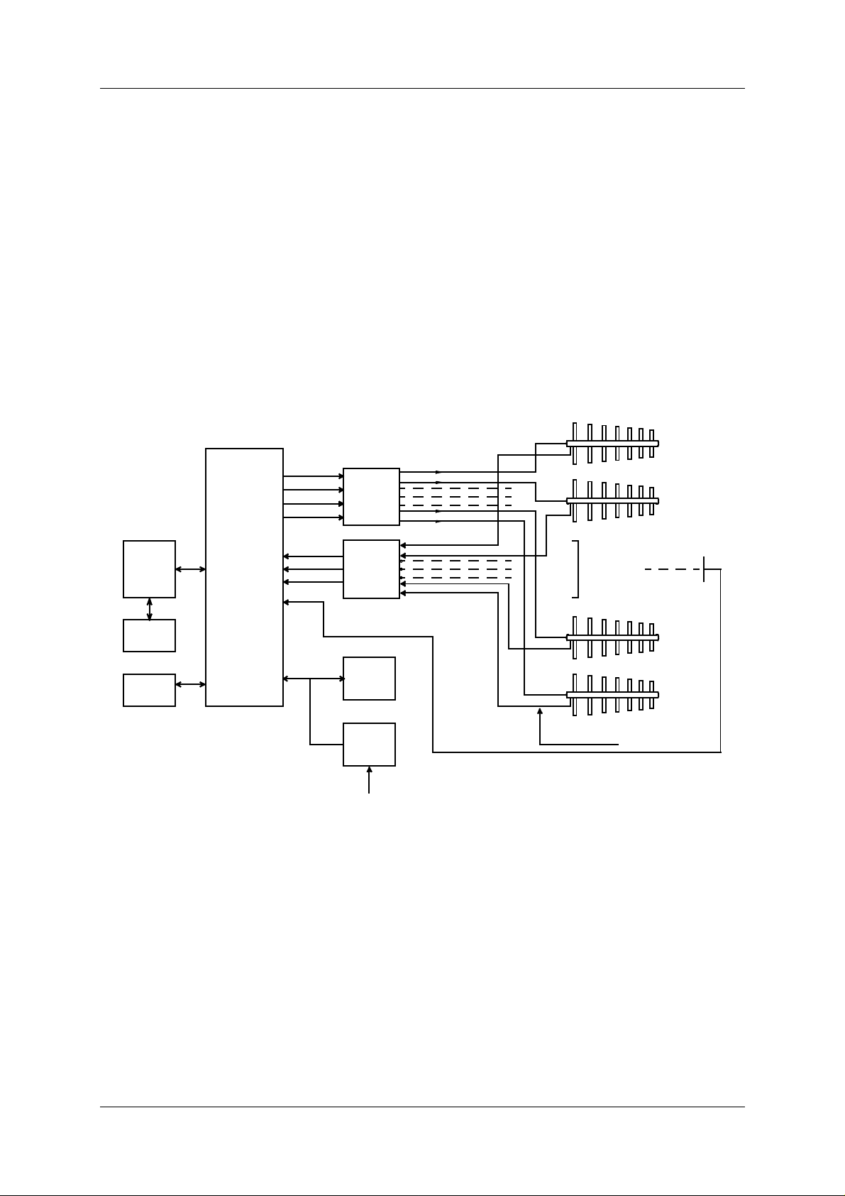
The NM 7000-series Localizers comprises the following units or sub-systems:
• Localizer Cabinet
• Power Supply
• Remote Control
• RMM System (Optional)
LOCALIZER ANTENNA
ILS LOCALIZER
TRANSMITTER
ARRAY
ILS Localizer
REMOTE
CONTROL
UNIT
SLAVE
PANEL
RMM
SYSTEM
TRANSMITTER
AND
MODULATOR
I and II
MONITOR
I and II
CSB CL
SBO CL
CSB CLR*
SBO CLR*
CL
CLR*
DS
NF
ANTENNA
DISTRIBUTION NETW.
MONITOR
NETWORK
24V
BATTERY
POWER
SUPPLY
MAINS INPUT
220V/110V AC
RUNWAY CL.
MONITOR
OUTPUT PROBE
* CLR SIGNALS N/A on single-frequency equipment
HBK204-1
Figure 1-1 LLZ block diagram
The Antenna System with distribution and monitor networks are described in a separate manual.
The Localizer cabinet comprises:
• Dual transmitter/m odulators
• Dual monitors in "2 out of 2" voting
• Priority and change-over system with local control panel
• Remote monitoring system with local displa y and RS-232 ports for local and remote PC
connections.
The Power supply is a separate, wall mounted unit. Back-up batteries are float charged, and
©1999 Navia Aviation AS 21833-3.4 SYSTEM DESCRIPTION
1-1
Page 14

OPERATING MANUAL
INSTRUMENT LANDING SYSTEM
NORMARC 7013
are connected to the LLZ cabinet.
The Remote Control unit is intended for installation in the tower or a technical room to give
remote control and status indication. An optional Remote Slave panel can be used if control
and status indication is required i n ad ditional positions.
The RMM system comprises the built-in RMS system in the LLZ cabinet, and a data program
running on a standard PC. The PC can be connected directly to the cabinet , or by mo dems
through leased or switched telephone lines.
1.2 Abbreviations
AC Alternating Current
ADC Analog to Digital Converter
AGC Automatic Gain Control
CL Course Line
CLR Clearance
COU Course
CPU Central Processing Unit
CS Course Sector
DAC Digital to Analog Converter
DC Di rect Current
DDM Difference in Depth of Modulation
DF Difference Frequency
DL DC Loop
DS Displacement Sensitivity
DSP Digital Signal Processor
EEPROM Electrically Erasable Progammable Read Only Memory
EMC ElectroMagnetic Compatibility
EMI ElectroMagnetic Interference
EPROM Erasable Programmable Read Only Memory
FFT Fast Fourier Transfor m
FIFO First-In-First-Out
FPGA Field Programmable Gate Array
GPA Glidepath Power amplifier Assembly
I/F InterFace
I²C Inter Integrated Circuit
IIC Same as I²C
ILS Instrument Landing System
LED Light Emitting Diode
LF Low Frequency
LLZ Localizer
LPA Localizer Power amplifier Assembly
LRU Line Replacable Unit
MCU Monitor Combiner Unit
NAV NAVigation signals
NF Near Field
PC Personal Computer
RAM Random Access Memory
RF Radio Frequency
SYSTEM DESCRIPTION ©1999 Navia Aviation AS
1-2
21833-3.4
Page 15

INSTRUMENT LANDING SYSTEM
RMM Remote Maintenance Monitor
RMS Remote Monitoring System
ROM Read Only Memory
RTC Real Time Clock
SC Station Control
SDM Sum in Depth of Modulation
SPA Same Parameter Alarm
SRAM Static Random Access Memory
STB Standby
SW SoftWare
TRM TeRMinator
TX Transmitter
UART Universal Asynchronous Receiver Transmitter
OPERATING MANUALNORMARC 7013
©1999 Navia Aviation AS 21833-3.4 SYSTEM DESCRIPTION
1-3
Page 16

OPERATING MANUAL
NORMARC 7013
INSTRUMENT LANDING SYSTEM
SYSTEM DESCRIPTION ©1999 Navia Aviation AS
1-4
21833-3.4
Page 17

INSTRUMENT LANDING SYSTEM
2 Technical specifications
NM 7013 Two-Frequency Localizer Cabinet.
2.1 Signal Minimum Performance LLZ
Transmitter
Frequency range 108-112 MHz
Frequency tolerance +
Output power (CSB) 5-15 W adjustable
Harmonic radiation 2.5 uW maximum
RF difference frequency (2-freq. only) 10 kHz +
Spurious 25 uW maximum
Output power stability +
CSB/SBO stability +
Modulator
Modulation depth 90/150 Hz 20%
Adjustable range 10-25%
SDM stability +
DDM stability +
Frequency tolerance +
Total harmonic distortion (90/150 Hz) 1% maximum
Phase locking (90 Hz to 150 Hz) 5° maximum ref 150 Hz
SBO phaser adjustment range +
OPERATING MANUALNORMARC 7013
0.002%
2 kHz
0.2 dB
0.3 dB / +-5°
0.3% SDM
0.1% DDM
0.05 Hz
10°
Identity keyer
Modulation frequency 1020 Hz +
10 Hz
Modulation depth 5-15% adjustable
Distortion 6% maximum
Speed of identification 7 Words/min. approx.
Monitoring
Alarm functions Adjustable range (*)
RF power reduction 1-5 dB
Change of nominal CL +
Change of nominal DS from nominal value +
Change of nominal CLR (2-freq. only) +
Change of nominal NF +
Change of nominal SDM +
Difference frequency (2-f req. only) +
4-25 uA
10-50 uA
10-60 uA
4-25 uA
2-6% SDM
2-5 kHz
Total period of radiation out of tolerance 1-10 sec
Additional NF delay 0-20 sec
Line break, ILS-remote control (disable
optional).
Identification lost or continuous (optional)
Monitor input levels
Adjustment range, nominal level: -5 to –34 dBm
©1999 Navia Aviation AS 21833-3.4 Technical specifications
2-1
Page 18

OPERATING MANUAL
NORMARC 7013
INSTRUMENT LANDING SYSTEM
AGC range for less than 1% change in
SDM
Monitor stability at nominal levels:
RF power values +
DDM values +
SDM values +
Warning functions:
RF power reduction 40-75% of alarm limit
Change of nominal CL 40-75% of alarm limit
Change of nominal DS 40-75% of alarm limit
Change of nominal CLR 40-75% of alarm limit
Change of nominal NF 40-75% of alarm limit
Change of nominal SDM 40-75% of alarm limit
Difference frequency 40-75% of alarm limit
Mains failure
Remote control
Data transmission medium 2-wire line, 600 ohm
Data modulation serial, FSK
Transmitter level -10dBm +
Receiver dynamic range -10dBm to -34dBm
5 dB
0,2 dB
1 uA
0,5% SDM
2 dB
(*): Asymmetrical limits are possible
2.2 Environmental characte ristics
Operating temperature: -10 to +55 °
Storage temperature - 30 to +60 °
2.3 EMC characteristics
EMR: EN 55022 class B
Spurious and harmonics: CISPR 22
2.4 Mechanical character istics
Dimensions: (HxBxW)
ILS Rack: 1020x600x500 mm
Remote control: 129x71x170 mm
Slave panels: 129x41x170 mm
Weight: 85 kg - 95 kg depending on model
The ILS rack is wall mounted. The remote control an d slave panel s fit a st andard 3U (132mm)
high 19" subrack.
2.5 Power supply
External supply:
Technical specifications ©1999 Navia Aviation AS
2-2
21833-3.4
Page 19

INSTRUMENT LANDING SYSTEM
Input voltage: 230V +15%/-20%,45-65 Hz or 120V +15%/-20%,
Output voltage: 27,6V
Output current: 20A max
ILS cabinet:
Input voltage: 22-28V DC
Current consumption: 8A – 14A depending on configuration
Stand-by battery 24V DC nominal, 85 Ah-110Ah valve regulated
OPERATING MANUALNORMARC 7013
45-65 Hz
lead-acid battery recommended
©1999 Navia Aviation AS 21833-3.4 Technical specifications
2-3
Page 20

OPERATING MANUAL
NORMARC 7013
INSTRUMENT LANDING SYSTEM
Technical specifications ©1999 Navia Aviation AS
2-4
21833-3.4
Page 21
OPERATING MANUALNORMARC 7013
INSTRUMENT LANDING SYSTEM
PART II OPERATION
3 Main cabinet
3.1 Power on/off
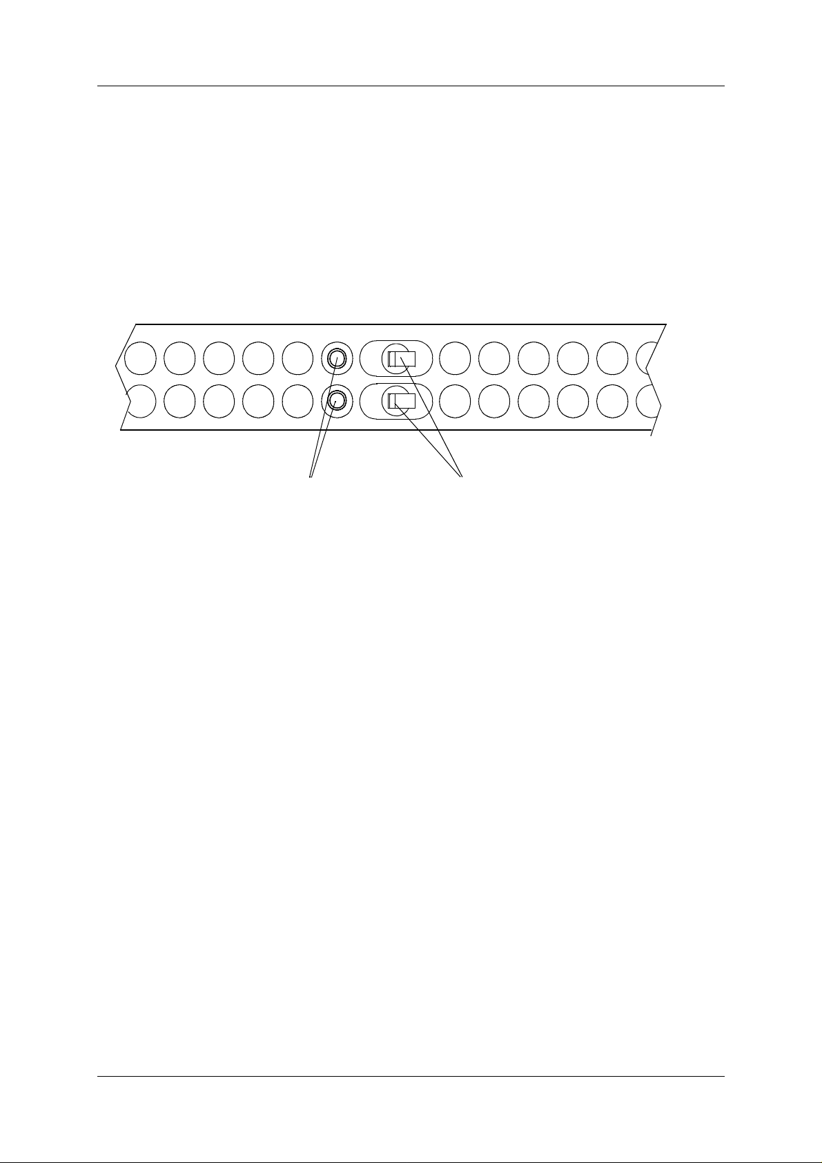
The power ON/OFF switches are located on front of the main cabinet. Adjacent to the
switches are GND sockets for connecting wrist st rap to ensure ESD-protected environment
when performing maintenance operations.
1 1
POWER ON/OFFGND SOCKETS
Figure 3-1 Power ON/OFF and GND Sockets Location
HBK548-1
©1999 Navia Aviation AS 21833-3.4 Main cabinet
3-1
Page 22
OPERATING MANUAL
3.2 Local Control Operation
NORMARC 7013
INSTRUMENT LANDING SYSTEM
PARAM
DISAGR
BATT
IDENT
MAINT
STBY
SERVICE
ALARM
WARNING
NORMAL
ON/
OFF
LOCAL
CHANGE
OVER
LAMP TEST
MANUAL
TX1
TX1
TX2
COURSE
CLR
TX TO AIR
MAIN
TX2
INTERLOCK
OVERRIDE
REMOTE
AUTO
WRITE
PROTECT
HBK 551/2
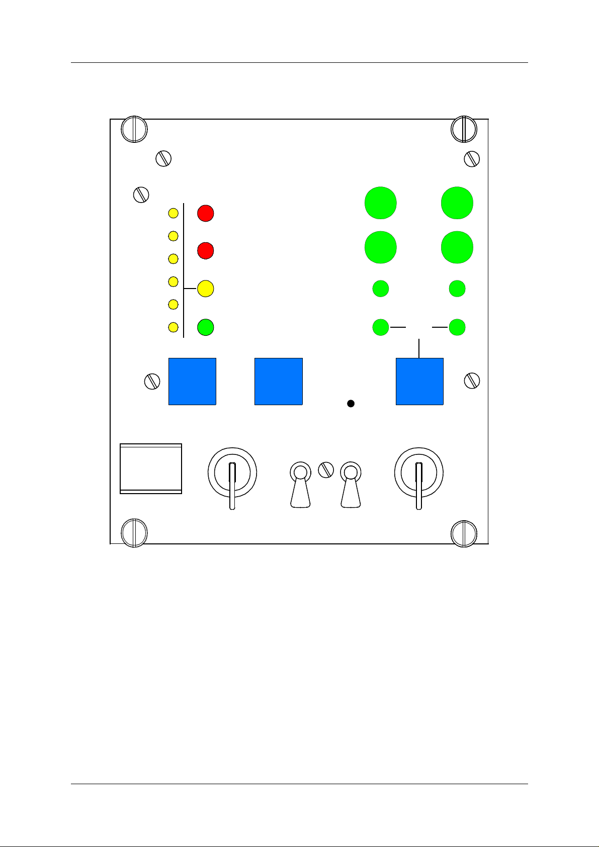
Figure 3-2 LC1217A front panel
3.2.1 Glossary
Changeover The transition from a normal ILS «on» state (coax pos=main select and active
main transmitters on air) to a normal ILS «standby on» state (coax pos. not
equal to main select, and standby transmitt ers active on air).
Shutdown The transition from any ILS state to a normal ILS «off» state (coax pos=main
select and no active transmitters).
Automatic When the ILS is in automat ic mode of operati on, any detecte d alarm(s) wil l lead
to either CHANGEOVER or SHUTDOWN.
Manual When the ILS is in manual mode of operation, the ILS state will not change if
alarm(s) are detected.
Interlock When an ILS is in active interlock mode (the interl ock signal is an input to the
Main cabinet ©1999 Navia Aviation AS
3-2
21833-3.4
Page 23
INSTRUMENT LANDING SYSTEM
remote control), the ILS wil l turn of f al l active trans mitters and not allow them to
be turned on before the interlock condition is removed. This signal overrides
manual mode of operation.
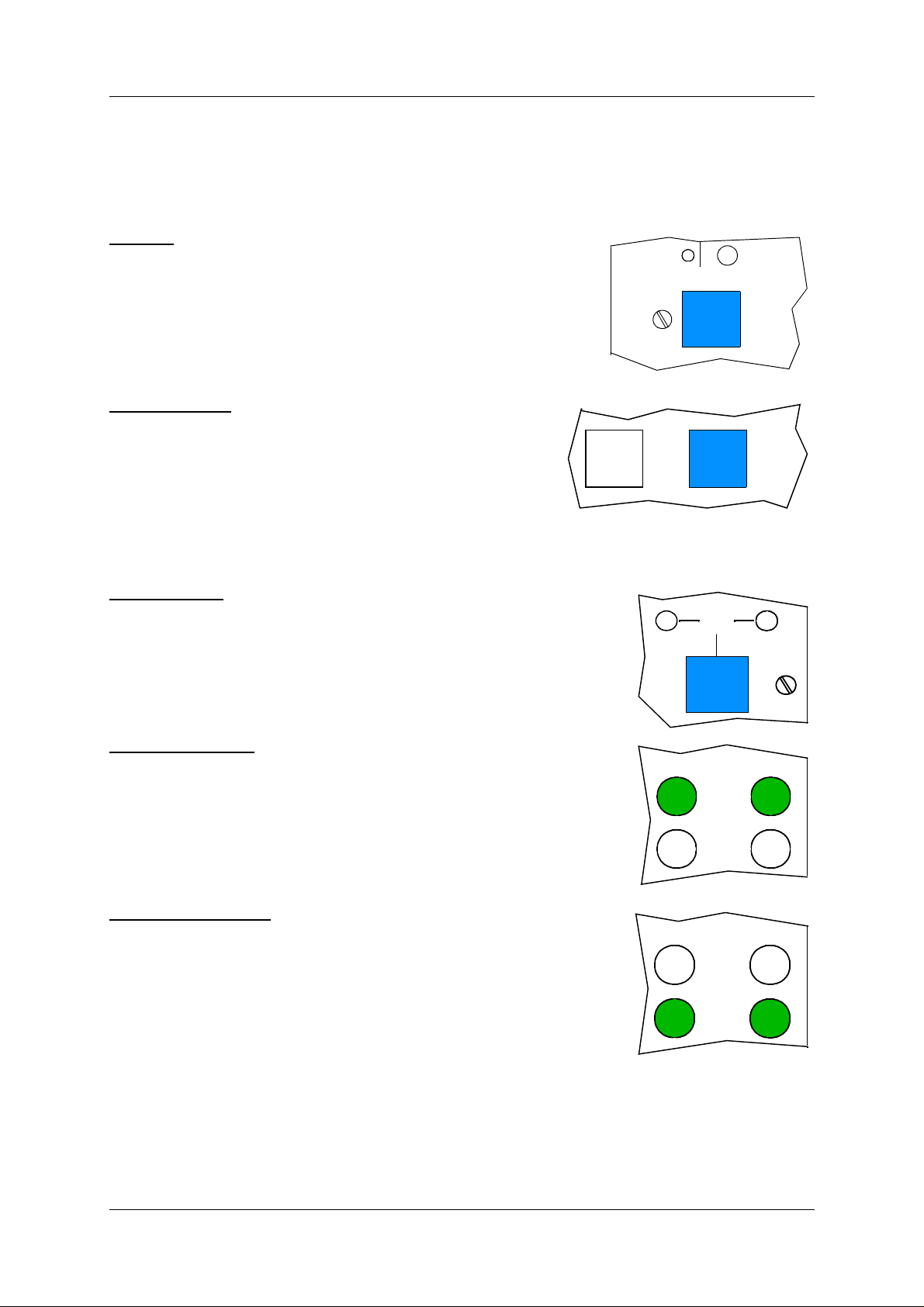
3.2.2 Pushbuttons
OPERATING MANUALNORMARC 7013
ON/OFF
Used to:
• Toggle the ILS on/off.
Valid when:
• The LOCAL/REMOTE switch must be in LOCAL position, and
• The interlock signal is not active if the ILS is configured for
interlock.
CHANGEOVER
Used to:
• Toggle the coax relay and transmitters between TX1/
TX2 as the active transmitter(s).
Valid when:
• The LOCAL/REMOTE switch is in LOCAL position, and
• The ILS is «on» when the MANUAL/AUTO switch is in
AUTO position.
MAIN SELECT
Used to:
• Toggle between TX1/TX2 as the main transmitter.
Valid when:
• The LOCAL/REMOTE switch is in LOCAL position.
STBY
ON/
OFF
HBK604-1
TX1
NORMAL
ON/
OFF
HBK603-1
CHANGE
OVER
MAIN
TX2
COURSE TX1/TX2
Used to:
• Toggle the COURSE TX1/TX2 on/off.
Valid when:
• LOCAL/REMOTE switch is in LOCAL position, and
• MANUAL/AUTO switch is in MANUAL position, and
• The interlock signal is active if the ILS is configured for interlock.
CleaRance TX1/TX2
Used to:
• Used to toggle the CLEARANCE TX1/TX2 on/off.
Valid when:
• CLEARANCE transmitters are present, and
• LOCAL/REMOTE switch is in LOCAL position, and
• MANUAL/AUTO switch is in MANUAL position, and
• The interlock signal is active if the ILS is configured for interlock.
3.2.3 Switches/Switchlocks
TX1
TX1
HBK605-1
TX2
COURSE
CLR
HBK606-1
TX2
COURSE
CLR
HBK607-1
©1999 Navia Aviation AS 21833-3.4 Main cabinet
3-3
Page 24
OPERATING MANUAL
NORMARC 7013
INSTRUMENT LANDING SYSTEM
LOCAL / REMOTE
Used to:
• Select between LOCAL and REMOTE mode of operation. REMOTE mode of
operation will inhibit use of the local push-button (as described above) and
the use of the local seri al communication port for enter ing RMS access level
2 and 3. LOCAL mode of operation will inhi bit use o f the remote con trol pushbuttons (ON/OFF, CHANGEOVER) and the use of the remote serial communication ports for entering RMS access level 2 and 3.
Valid when:
• The LOCAL/REMOTE switch is in LOCAL position.
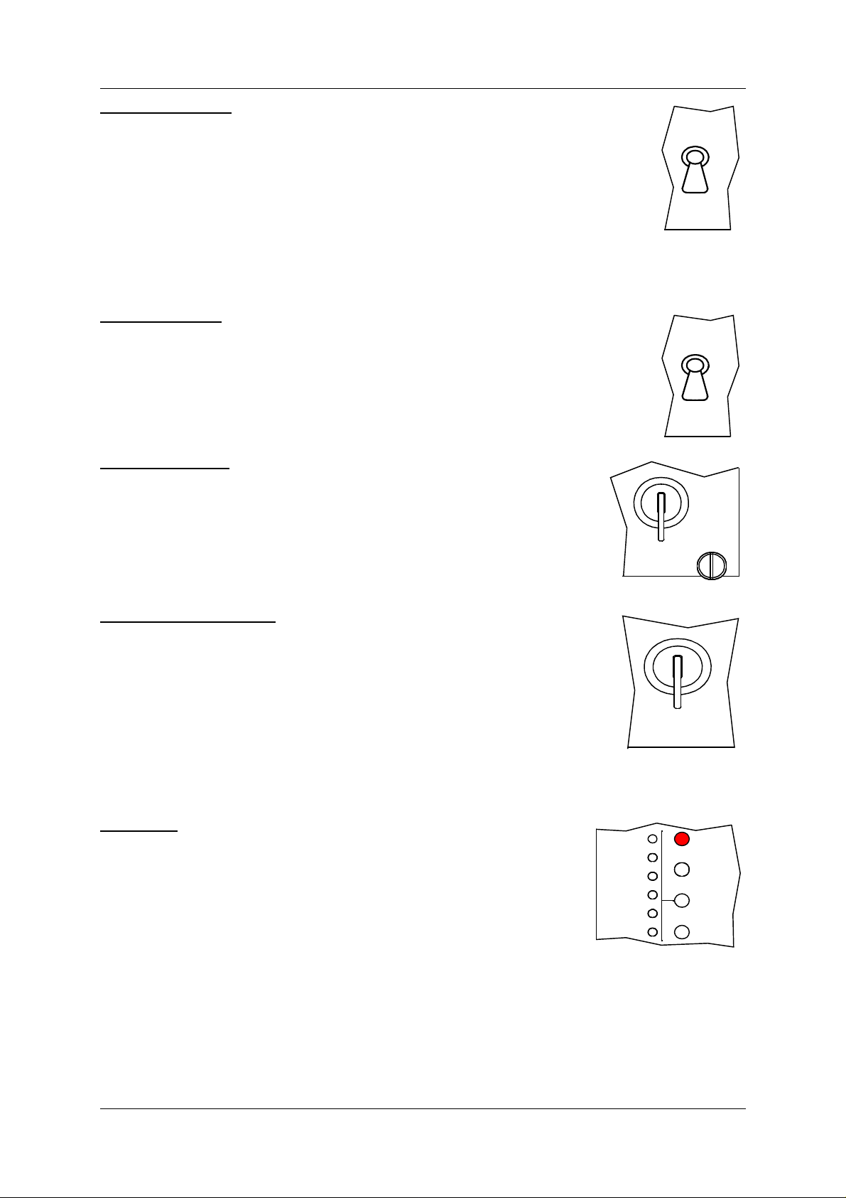
MANUAL / AUTO
Used to:
• Select between AUTOMATIC and MANUAL mode of operation.
Valid when:
• The LOCAL/REMOTE switch is in LOCAL position.
WRITE PROTECT
Used to:
• Prevent changing of alarm limits and other ILS parameter adjustments. Setting this switchl o ck in vertical/horizontal po sition will prevent/not prevent entering of access level 3
Valid when:
•Always
HBK611-1
LOCAL
REMOTE
HBK609-1
MANUAL
AUTO
HBK610-1
WRITE
PROTECT
INTERLOCK OVERRIDE
Used to:
• Override the interlock input to allow testing of transmitters. Using this
function will allow the local panel pushbuttons to be used (ON/OFF,
CHANGEOVER and the individual TX on/off keys).
Valid when:
• The LOCAL/REMOTE switch is in LOCAL position, and
• The MANUAL/AUTO switch is in MANUAL position.
INTERLOCK
OVERRIDE
HBK612-1
3.2.4 System Status Indications
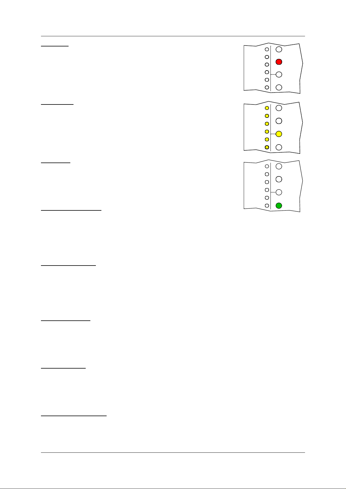
SERVICE
Used to:
• Indicate that the ILS is currently in SERVICE mode of operation.
This will also set the remote control to alarm state.
Activated by:
• EXTERNAL SERVICE line forced low (by LF1223A set in service
condition), or
PARAM
DISAGR
BATT
IDENT
MAINT
STBY
HBK608-1
SERVICE
ALARM
WARNING
NORMAL
• RMS in access level 2 or 3, or
• The LOCAL/REMOTE switch is in LOCAL position, or
• The MANUAL/AUTO switch is in MANUAL position, or
• MANUAL mode entered from RMS, or
• Mismatch between the WRITE PROTECT switch and configuration strap setting on U6
(strap position 6-15).
Main cabinet ©1999 Navia Aviation AS
21833-3.4
3-4
Page 25
INSTRUMENT LANDING SYSTEM
OPERATING MANUALNORMARC 7013
ALARM
Used to:
• Indicate that the ILS has detected an alarm condition.
Activated by:
• One or more alarms present.
WARNING
Used to:
• Indicate that the ILS has detected one or more warning conditions.
Activated by:
• Warni ng condition(s) detected by RMS.
NORMAL
Used to:
• Indicate that no alarm conditions are detected by the ILS.
Activated by:
• No alarms present.
PARAMeter Warni ng:
PARAM
DISAGR
BATT
IDENT
MAINT
STBY
HBK613-1
PARAM
DISAGR
BATT
IDENT
MAINT
STBY
HBK614-1
PARAM
DISAGR
BATT
IDENT
MAINT
STBY
HBK615-1
SERVICE
ALARM
WARNING
NORMAL
SERVICE
ALARM
WARNING
NORMAL
SERVICE
ALARM
WARNING
NORMAL
Used to:
• Indicate that there are one or more monitor parameter warnings present. The warnings
from the monitor 1/monitor 2 are voted before displayed.
Activated by:
• One or more monitor parameters outside the warning limits.
Monitor DISAGRee
Used to:
• Indicate that monitor 1 and monitor 2 disagrees on which pa rameters that are in alarm
state.
Activated by:
• Difference in monitor 1/monitor 2 alarm detection.
BATTery Warning
Used to:
• Indicate that the ILS is running using the 27V battery.
Activated by:
• Loss of mains for charging the 27V battery.
IDENT Warning
Used to:
• Indicate that the ident is faulty for LLZ.
Activated by:
• Loss of ident Morse coding for LLZ.
MAINTenance Warning
Used to:
• Indicate that one or more of the maintenance parameter warnings detected.
Activated by:
©1999 Navia Aviation AS 21833-3.4 Main cabinet
3-5
Page 26
OPERATING MANUAL
INSTRUMENT LANDING SYSTEM
NORMARC 7013
• One or more maintenance parameters faulty or outside limits.
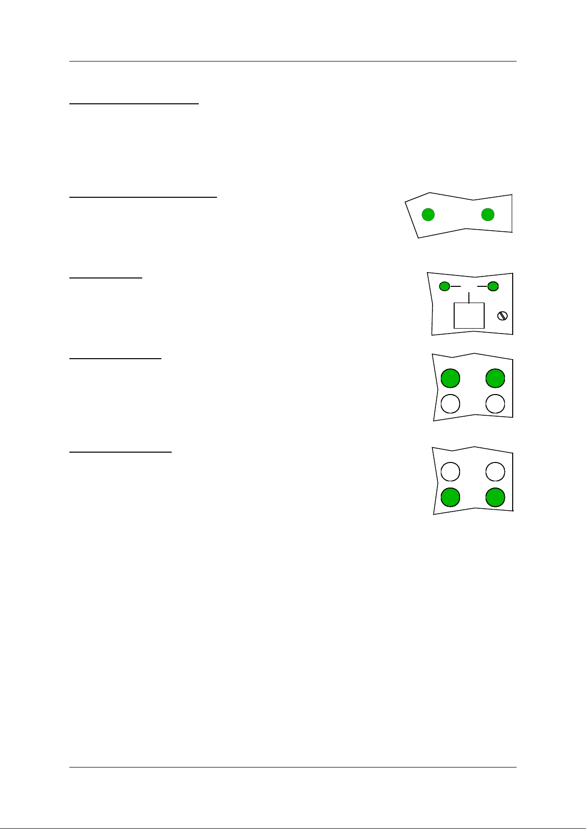
STandBY transmitter on air
Used to:
• Indicate that coax position dir ects the standby transmitter s to the antenna and the main
transmitters to the dummy load.
Activated by:
• Coax position differs from transmitter main select.
COAXIAL POSITION TX1/TX2
Used to:
• Indicate the position of the coax relay.
Activated by:
COAXIAL
POSITION
HBK616-1
• Coax relay position.
MAIN TX1/TX2
Used to:
• Indicate which transmitter that i s defined as main.
Activated by:
• Main select position.
COURSE TX1/TX2
Used to:
• Indicate the status of COURSE 1/COURSE 2 status . If illuminated the
transmitter is on.
Activated by:
• Transmitter «on».
CleaRance TX1/TX2
Used to:
• Indicate the status of CLEARANCE 1/CLEARANCE 2 status. If illuminated the transmitter is on.
Activated by:
• Transmitter «on».
TX1
HBK617-1
TX1
TX1
MAIN
TX2
TX2
COURSE
CLR
HBK606-1
TX2
COURSE
CLR
HBK607-1
Main cabinet ©1999 Navia Aviation AS
21833-3.4
3-6
Page 27
INSTRUMENT LANDING SYSTEM
3.3 Local Keyboard/Display Operation
OPERATING MANUALNORMARC 7013
PREVESC
NEXT ENTER
QUICK
-+
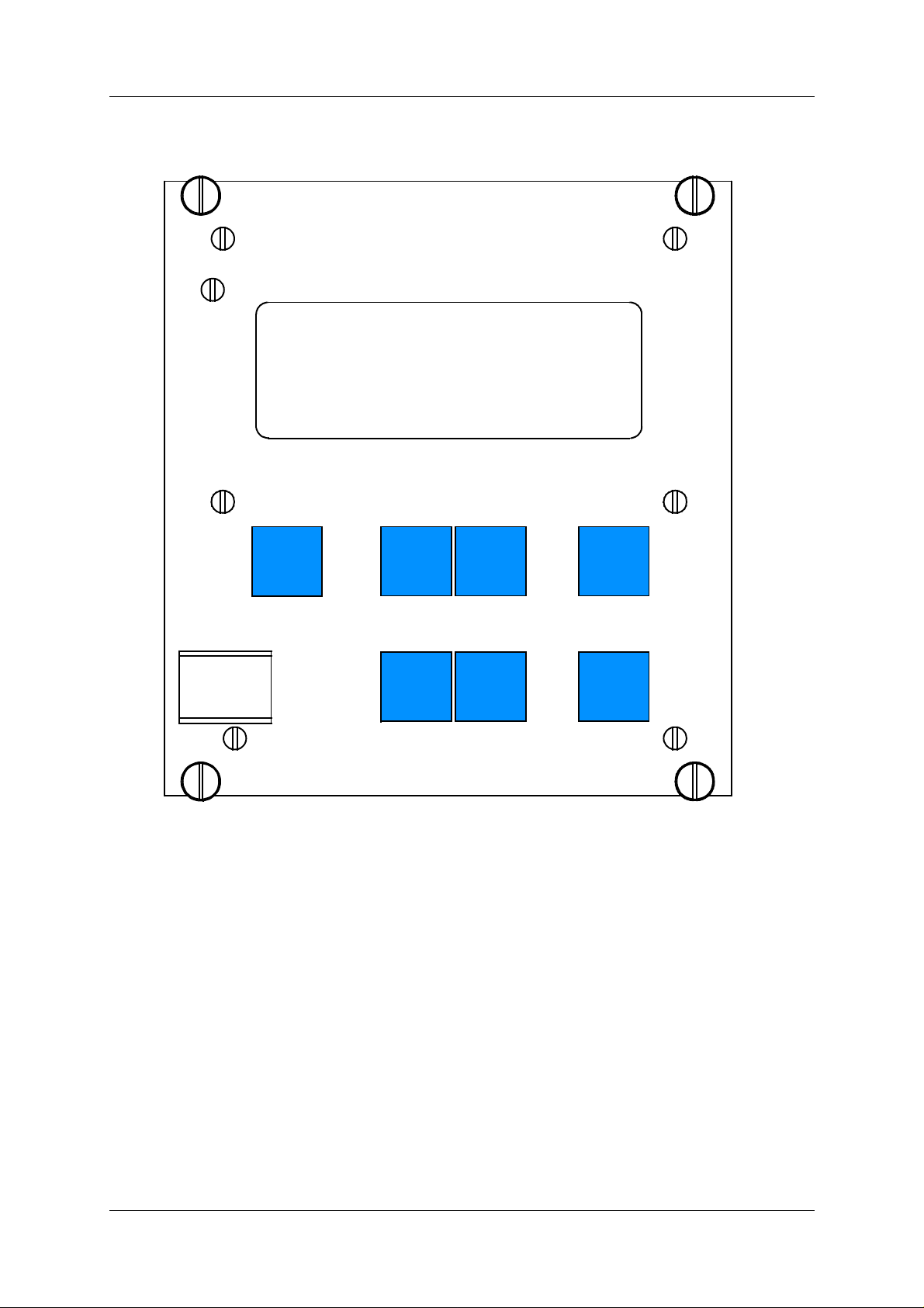
Figure 3-3 The local keyboard/display
3.3.1 The menu structure.
The front panel menu system includes a 20x4character LCD with 7 dedicated pushbutton
keys. The system is organised as a top-down menu tree-st ructure where the main menu is the
default entering point.
READ
HBK550-1
The main menu screen has three menu-options. The options are div ided into the th ree access
levels; level 1 with basic readout functions, level 2 with test and control func ti ons and level 3
with permanent system parameter setti ngs and configuration changes.
©1999 Navia Aviation AS 21833-3.4 Main cabinet
3-7
Page 28

OPERATING MANUAL
INSTRUMENT LANDING SYSTEM
NORMARC 7013
>Read syst para L1
Local settings L2
Syst settings L3
Figure 3-4 The top level main menu screen.
3.3.2 Handling the different menuscreens.
The menu system consists of five basic screen types; menu-screens, readout-screens, toggle-screens, input/sto ring-screens, and the quick read screens.
3.3.2.1 The menu screen
The menu screen is controlled by the key-buttons: <PREV> <NEXT> <ENTER> and <ESC>.
The menu options are formatted as a l ong li st wher e eac h option hol ds one char act er li ne. If a
menu screen includes more than four options, a small arrow-indicator will be displayed in the
lower-right corner. This informs the user that more than four menu options are available. The
blinking arrow cursor left to the menu-t ext is controlled by the <NEXT> and <PREV> keys.
The <ENTER> key activates the menu options left to the arrow-cursor.
The <ESC> key brings the user one menu-level upwards or back in the menu-tree-structure.The menu scrolls down if the user pushes the <NEXT> key when the arrow-cursor is at
the lower line and the arrow indicator is displayed in the lower-right corner. The menu will in
the same way scroll upwards by pushing the <PREV>-key in a corresponding situation.
3.3.2.2 The readout screen
The readout screens display the various monitor and maintenance parameter readings. The
screens are entered by stepping through the menu options. The <ESC> key brings the user
back to the last menu-screen again. The parameter readings are continuously updated.
CL readout M1 M2
DDM.: 0.1% 0.1%
Al U +1.5% +1.5%
Wa U -1.5% -1.5%
Figure 3-5 A typical readout screen: CL DDM.
3.3.2.3 The toggle screens
The toggle screens offer the user to choose between two or more options. The options text is
enclosed by two blinking square-brackets. The plus «+» and minus «- » keys step through the
various options. The <ENTER> key activates the chosen toggle-option. The <ESC> keys
leaves the screen without activating any of the opti ons.
Main cabinet ©1999 Navia Aviation AS
3-8
21833-3.4
Page 29

OPERATING MANUALNORMARC 7013
INSTRUMENT LANDING SYSTEM
TX 1 90 Hz on/off
[90 Hz tone on]
Figure 3-6 A typical toggle screen: TX1 90Hz on/off.
3.3.2.4 Input/Store screen
The user can change the various parameter alarm and warning settings in the input/storingscreens. A virtual cursor is controlled by the <PREV> and <NEXT> keys. An input field number will blink if the cursor is moved to the correct positi on. The blinking limit val ues can now be
changed by pushing the plus «+» and minus «-» keys. If the input field is digital, the valid
options will be «False» and «T rue» when the plus «+» and minus «-» keys are pushed.
When all the input numbers in the screen are changed to th e preferred new valu es, the cursor
must be moved to the (STORE)-field in t he upper left corner. When the cursor is placed at this
(STORE)-field, the brackets will start blin king. The <ENTER> key will now store the new values on the screen in the ILS. The <ESC> key leaves the screen unchanged.
CL <store> M1 M2
DDM.: 0.1% 0.1%
Al U +1.5% +1.5%
Wa U -1.5% -1.5%
Figure 3-7 A typical input/store screen: CL DDM
3.3.2.5 The quick read screens
The quick read screens are access by pushing the <QUICK READ> key. The key toggles
between the original menu tree and the quick read screens. The <QUICK READ> button can
be pushed at all times, not changing the original menu-screens. The quick read screens
include only the basic monitor readings. The <PREV> and <NEXT> keys step through the
quick read screens.
CL %DDM %SDM RFv
M1 0.1 40.0 3.0
M2 0.1 40.0 3.0
Figure 3-8 A typical quick read screen: CL.
3.3.3 The access levels.
The level 3 menu options must be entered by typing a 4 character password. The level 2
menu can be entered as an ordinary menu-option.
3.3.3.1 Level 2
To enter the level 2 menu option, the front panel switches must be in the LOCAL and MANUAL positions. The remote panel acces s switch must also be in ACCESS position. The user is
©1999 Navia Aviation AS 21833-3.4 Main cabinet
3-9
Page 30

OPERATING MANUAL
INSTRUMENT LANDING SYSTEM
NORMARC 7013
denied access if the switches are not correctly set.
Local switch on
Front panel in
REMOTE position
Push <ESC>
Figure 3-9 An access denial screen: Switch in REMOTE position.
3.3.3.2 Level 3
To enter the level 3 menu option, the front panel switches must be as for level 2 access. In
addition the WRITE PROTECT switch must be in «ACCESS» position. The user must key a 4
character password to enter level 3 access. The access-screen is operated similarly to an
input/store-screen. The blink ing cursor is moved by the <PREV> and <NEXT> keys. A blinking input-field is changed by the plus «+» and minus «-» keys.
When the correct password is entered, the cursor must be moved to the <level 3 access>field. The brackets will then start blinking. The <ENTER> key will now bring the user to the
level3 options. The <ESC> key leaves the screen back to the main menu.
LEVEL ACCESS 3
m m
m m
<level3 access>
Figure 3-10 Level 3 access screen.
3.3.3.3 Leaving the access levels
If the user enters level 2 or 3, an extra menu line is added in the main menu screen. This is a
leave current access level option. The user must enter this menu option to quit the current
access level - typically when leaving th e ILS.
The access levels are also left when the front panel switches are changed to an illegal position. (e.g. switch in REMOTE position)
>Read syst para L1
Local settings L2
Syst settings L3
Leave access 3
Figure 3-11 The top level main menu screen: User i n level 3 access.
3.3.4 Function listing
The menu system includes the following functionality.
3.3.4.1 Level 1
Readout of all the monitor values, warning and alarm limits.
Readout of all the maintenance values and warning limits.
Readout of all the delays.
Readout of all the TX1 and TX2 configurations.
Main cabinet ©1999 Navia Aviation AS
3-10
21833-3.4
Page 31

OPERATING MANUALNORMARC 7013
INSTRUMENT LANDING SYSTEM
3.3.4.2 Level 2
Ident. configurations with morse si gnal sett ings to normal, cont inuous, TST or of f on TX1/TX2.
Local morse speaker on/off on the transmitters.
TX1 and TX2: test-signal 90 Hz or 150 Hz dominance on/off.
TX1 and TX2: 90/150 Hz on/off.
Communications.
3.3.4.3 Level 3
Settings of all the monitor warning and alarm li mits.
Settings of all the maintenance warning limits.
Settings of all the delays.
Settings of all the TX1 and TX2 configurations.
©1999 Navia Aviation AS 21833-3.4 Main cabinet
3-11
Page 32
3-12
Main cabinet ©1999 Navia Aviation AS
Top Menu
NORMARC A/S
- NM7013 2-freq. Localizer
<ESC>
Main Menu
Read system para L1
Syst tests L2
Syst settings L3
(Leave access 2/3)
Figure 3-12 The menu tree: The top levels
Syst tests
Read system para
Mon. parameters
21833-3.4
Maint. val. & lim.
System delays
TX configuration
<enter selection>
Ident config.
Test DDM signals
TX 90/150Hz on/off
Communications
Reset hist. storage
<enter selection>
<enter selection>
Password Menu
LEVEL ACCESS 3
m m
m m
<level3 access>
<correct password>
Syst settings
Mon. parameters
Maint. val. & lim.
System delays
TX configuration
<enter selection>
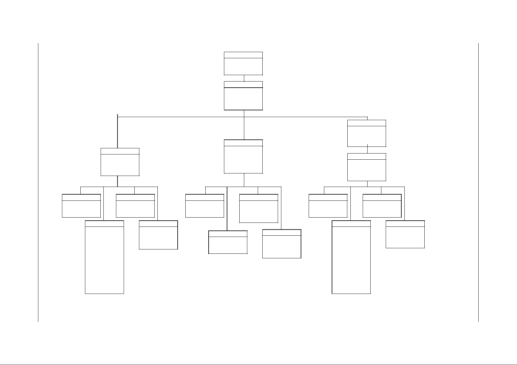
The top 3 levels of the menu tree is shown in Figure 3-12.
3.3.5 The menu tree
OPERATING MANUAL
Mon. parameters
Mon. 1&2 alarm par
Mon. 1&2 warn. par
Maint. val. & lim.
Monito r 1
Monito r 2
LF generator 1
LF generator 2
Mon 1 frontend
Mon 2 frontend
Oscillator 1
Oscillator 2
Course TX1 PA
Course TX2 PA
Clearance TX1 PA
Clearance TX2 PA
DC supplies
System delays
Mon1 delays
Mon2 delays
Maint delays
TX configuration
TX1 configuration
TX2 configuration
Test signals TX1
Test signals TX2
Ident config TX 90/150Hz on/o ff
Morse mode TX1
Morse mode TX2
Set ident speaker
Test DDM signals
Test sig TX1
Test sig TX2
TX1 90Hz on/off
TX1 150Hz on/off
TX2 90Hz on/off
TX2 150Hz on/off
Communications
Bitrate local port
Bitrate rem1 port
Bitrate rem2 port
Init modem
Mon. parameters
Mon. 1&2 alarm par
Mon. 1&2 warn. par
Maint. val. & lim.
Monitor 1
Monitor 2
LF generator 1
LF generator 2
Mon 1 frontend
Mon 2 frontend
Oscillator 1
Oscillator 2
Course TX1 PA
Course TX2 PA
Clearance TX1 PA
Clearance TX2 PA
DC supplies
System delays
Mon1 delays
Mon2 delays
Maint delays
TX configuration
TX1 configuration
TX2 configuration
Test signals TX1
Test signals TX2
HBK595-2
INSTRUMENT LANDING SYSTEM
NORMARC 7013
Page 33
INSTRUMENT LANDING SYSTEM
4 Tower Equipment
4.1 Remote Control Operation
PARAM
OPERATING MANUALNORMARC 7013
SILENCE
DISAGR
BATT
IDENT
MAINT
STBY
ALARM
WARNING
NORMAL
ON /
OFF
RMM
ACCESS GRANT
CHANGE
OVER
DENY
HBK566-1
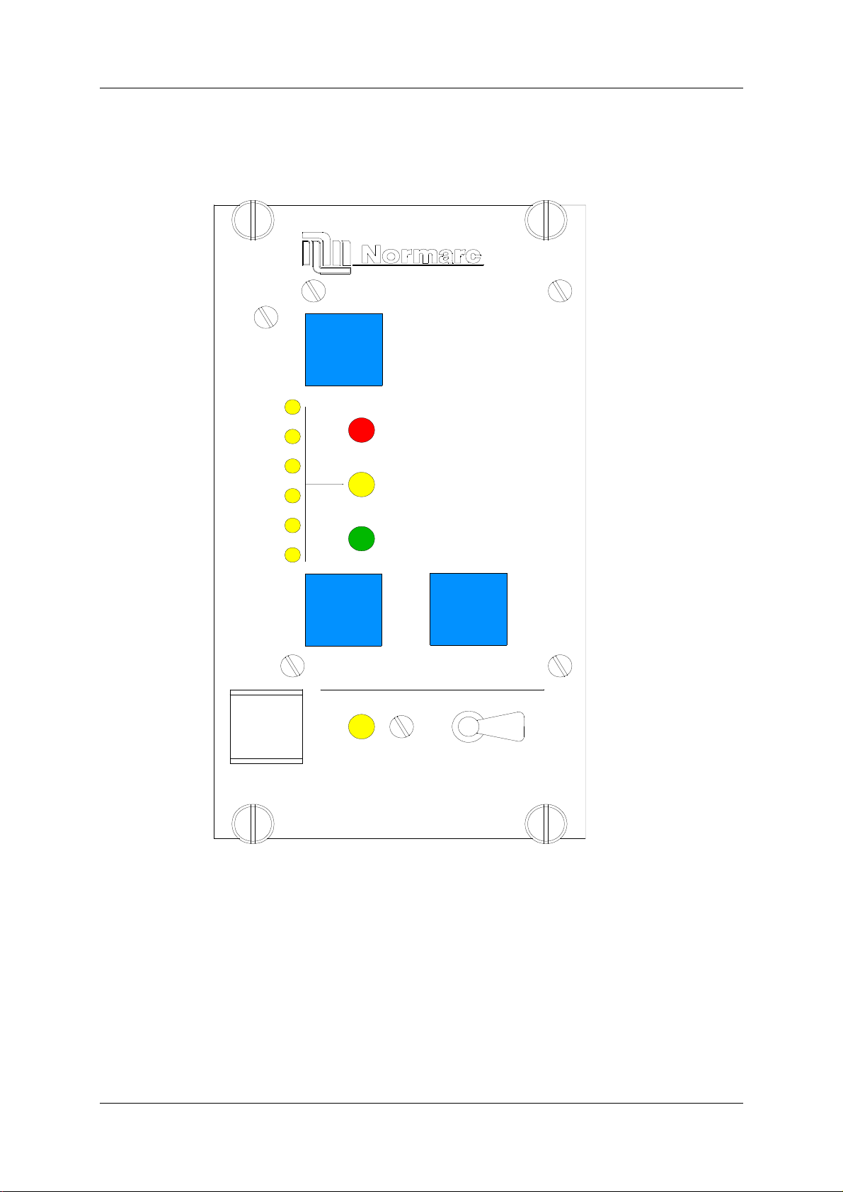
Figure 4-1 RF1242A front panel.
4.1.1 Glossary
INTERLOCK When an ILS is in active interlock mode (the interlock signal is an input to the
remote control), the ILS wil l turn of f al l active trans mitters and not allow them to
be turned on before the interlock condition is removed. This signal overrides
manual mode of operation.
4.1.2 Pushbuttons
©1999 Navia Aviation AS 21833-3.4 Tower Equipment
4-1
Page 34

OPERATING MANUAL
INSTRUMENT LANDING SYSTEM
NORMARC 7013
ON/OFF
Used to:
• Toggle the ILS on/off.
Valid when:
• The LOCAL/REMOTE switch must be in REMOTE position, and
• The interlock signal is not active if the ILS is configured for interlock.
CHANGE OVER
Used to:
• Toggle the coax relay and transmitters between TX1/TX2 as the active transmitte r(s).
Valid when:
• The LOCAL/REMOTE switch on the ILS is in REMOTE position, and
• The ILS is «on» when he MANUAL/AUTO switch is in AUTO position.
SILENCE
Used to:
• Turn off the audio alarm on the remote control (caused by remote status change from
NORMAL to ALARM). Also used for lamp test (all lamps are illuminated when this pushbutton is held down).
Valid when:
•Always.
4.1.3 Switches/Switchlocks
GRANT/DENY
Used to:
• Give access grant (access level 2/3) for RMS control of the ILS when the switch is in
GRANT position. NOTE! This switch may be override by configuration straps on U6 on
TC1216A (strap position 7-14). When this switch is in the DENY position no RMS access
(at access level 2/3) is allowed.
Valid when:
•Always.
4.1.4 System Status Indications
ALARM
Used to:
• Indicate that the ILS has detected an alarm condition.
Activated by:
• One or more alarms present on the ILS, or
• Communic a ti on failure with ILS.
WARNING
Used to:
• Indicate that the ILS has detected one or more warning conditions.
Activated by:
• Warni ng condition(s) detected by RMS.
NORMAL
Used to:
• Indicate that no alarm conditions are detected by the ILS.
Tower Equipment ©1999 Navia Aviation AS
4-2
21833-3.4
Page 35

OPERATING MANUALNORMARC 7013
INSTRUMENT LANDING SYSTEM
Activated by:
• No alarms present, and
• Communication with ILS is OK.
PARAMETER WARNING
Used to:
• Indicate that there are one or more monitor parameter warnings present.
Activated by:
• One or more monitor parameters outside the warning limits.
MONITOR DISAGREE
Used to:
• Indicate that there are one or more monitor parameter warnings present. The warnings
from the monitor 1/monitor 2 are voted before displayed.
Activated by:
• Difference in monitor 1/monitor 2 alarm detection.
BATTERY WARNING
Used to:
• Indicate that the ILS is running using the 27V battery.
Activated by:
• Loss of mains for charging the 27V battery.
IDENT WARNING
Used to:
• Indicate that the ident is faulty for LLZ.
Activated by:
• Loss of ident Morse coding for LLZ.
MAINTENANCE WARNING
Used to:
• Indicate that one or more of the maintenance parameter warnings detected.
Activated by:
• One or more maintenance parameters faulty or outside limits.
STANDBY TRANSMITTER ON AIR
Used to:
• Indicate that coax position dir ects the standby transmitter s to the antenna and the main
transmitters to the dummy load.
Activated by:
• Coax position differs from transmitter main select.
ALARM BUZZER
Used to:
• Indicate that a transition from NORMAL to ALARM has occurred. Reset by pre ssing
SILENCE push-button.
Activated by:
• Remote control state transition from NORMAL to ALARM.
©1999 Navia Aviation AS 21833-3.4 Tower Equipment
4-3
Page 36
OPERATING MANUAL
ACCESS
Used to:
• Indicate that access level 2/3 has been granted for RMS control.
Activated by:
• Grant/Deny switchlock is in GRANT position.
4.2 Remote Slave Operation
SILENCE
NORMARC 7013
INSTRUMENT LANDING SYSTEM
ALARM
WARNING
NORMAL
ON/
OFF
HBK599-1
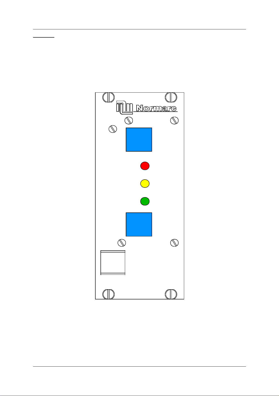
Figure 4-2 SF1344A front panel.
4.2.1 Glossary
INTERLOCK When an ILS is in active interlock mode (the interlock signal is an input to the
remote control), the ILS wil l turn of f al l active trans mitters and not allow them to
be turned on before the interlock condition is removed. This signal overrides
manual mode of operation.
Tower Equipment ©1999 Navia Aviation AS
4-4
21833-3.4
Page 37

OPERATING MANUALNORMARC 7013
INSTRUMENT LANDING SYSTEM
4.2.2 Pushbuttons
ON/OFF
Used to:
• Toggle the ILS on/off.
Valid when:
• The LOCAL/REMOTE switch must be in REMOTE position, and
• The interlock signal is not active if the ILS is configured for interlock.
SILENCE
Used to:
• Turn off the audio alarm on the slave panel (generated by remote control). Also used for
lamp test (all lamps are illuminated when this push- button is held down).
Valid when:
•Always.
4.2.3 System Status Indications
ALARM
Used to:
• Indicate that the ILS has detected an alarm condition.
Activated by:
• One or more alarms present on the ILS, or
• Communic a ti on failure with ILS.
WARNING
Used to:
• Indicate that the ILS has detected one or more warning conditions.
Activated by:
• Warni ng condition(s) detected by RMS.
NORMAL
Used to:
• Indicate that no alarm conditions are detected by the ILS.
Activated by:
• No alarms present, and
• Communication with ILS is OK.
4.3 Interlock Switch Operation
The interlock function is used when mutual exclusive operation on different ILS systems is
required. An active interlock for a station shall prevent transmission of ILS signals. The interlock signal is connected to the remote contr ol RC1241 and transmitted to the ILS through the
remote control connection.
The interlock function on the ILS is enabled/disabled from configuration settings on the
TC1216A. The rest of this chapter describes an ILS configured for interlock.
When an active ILS receives an active interlock signal, the ILS performs a shutdown. If the
interlock signal is deactivated, the ILS will automatically be turned on after a 20 second delay
period.
©1999 Navia Aviation AS 21833-3.4 Tower Equipment
4-5
Page 38

OPERATING MANUAL
INSTRUMENT LANDING SYSTEM
NORMARC 7013
For maintenance purposes, an interlock override function has been implemented. This function makes it possible to operate the ILS locally in manual mode with an active interlock signal. To activate the interlock override function the foll owing conditions must be met:
• LOCAL/REMOTE switch must be in LOCAL position,
• AUTO/MANUAL switch must be in MANUAL position and
• INTERLOCK OVERRIDE switchlock must be set in horizontal position.
The remote control will always be set in ALARM state when the inter lock override function is
activated.
Tower Equipment ©1999 Navia Aviation AS
4-6
21833-3.4
Page 39

OPERATING MANUALNORMARC 7013
INSTRUMENT LANDING SYSTEM
5 Remote Maintenance and Monitoring Software
This chapter is the user manual for the Remote Maintenance and Moni toring (RMM) s oftware.
Version 3.9 of the RMM software is covered in this chapter. This version can be used to con-
nect to ILS cabinets with version 5 up to and including version 12 of the RMS software.
5.1 Introduction
This paragraph gives a brief description of this user manual, the program and the system
requirements.
5.1.1 Description
This manual describes how to use the NM70x x remote monitoring software. The remote monitoring software consists of software running in the ILS rack and on software running on IBM/
PC's and compatibles. The purpose of the system is to retrieve status and measurements
from the ILS rack and to change ILS operation and parameters from a remote site. The
retrieved data can be displayed and further processed by programs on the PC.
For example, the ILS data can be
• Displayed on the screen.
• Saved on disk for later use.
• Exported to other programs for graphi cal display of parameter variati ons.
5.1.2 Available versions
The NM7000 RMM program is available in a DOS version and a 32 bit version for Windows
95/NT. Both versions are distributed together . Depending on the operating syst em installed on
the PC, the user must install one of thes e versions.
5.1.3 System requirements
The PC running the DOS version of the software must be equipped with:
• 386DX33 based computer
• DOS 3.0 or later
• a hard disk
•4 Mbyte RAM
• HIMEM installed
• a RS-232 serial port connected to a Hayes compatible 2400 baud modem
• a printer port & printer, if printouts are desired
For Windows 95 and NT the following are acceptable minimum configurations:
95: 486x33 and 8 MB RAM
NT: Minimum 486x66 and 16-20 MB RAM
A recommended configuration for running the DOS version in cludes the following:
• a 486 based computer or better
• a mathematical co-processor (486DX internal is satisfactory)
• a VGA monitor
• DOS 6.0 or later
• I/O board with 16550 UART
©1999 Navia Aviation AS 21833-3.4 Remote Maintenance and Monitoring
5-1
Page 40

OPERATING MANUAL
INSTRUMENT LANDING SYSTEM
NORMARC 7013
If a 386- or a slow 486-based PC is used, it is recommended to drop the bitrate to 2400 or
4800 bps.
If a mouse is available, it is supported by the RMM software.
5.1.4 Running under Microsoft Windows 3.xx
Neither the DOS version nor the Win95 /NT v ersion of the RMM program runs under Windows
3.xx. The DOS version can, of course, be start ed on a PC with Windows 3.xx inst alled as long
as Windows is not also started.
If the RMM-software is run ning on a sl ow PC with Wind ows 95 or NT, avoid to st art up sever al
other applications. This to ensure sufficient processor-time is available for data processing in
the NM 7000 RMM.
5.1.5 How to use this manual
The user interface of the RMM software is very similar to the one used in Microsoft Windows.
If you are familiar with using Windows programs, you will easi ly understand how to operate
this program, and you can skip Chapter 5.2. The next chapters describe each feature of the
program. You may want to read these chapters to learn how use the RMM software.
5.1.6 Starting the RMM software
To install the RMM PC Software, create a directory named NM7000 on the hard disk. Then
copy the contents of the NMS152A (DOS) or NMS152B (Win95/NT) RMM PC SW floppy to
this directory.
To start the program, make the RMM system directory your current directory. Then start
NM7000.EXE (DOS) or NM7000.BAT (Win95/NT).
If you are not familiar wit h DOS commands, the abov e step s can be perf ormed with t he follo wing commands:
CD\NM7000↵
NM7000↵
5.2 User interface components
There are three visible components t o the RMM software: the menu bar at t he top, the window
area in the middle and the status line at the bottom of the screen. The next few sect ions
describe these components, and the information that they display.
5.2.1 The menu bar and menus
The menu bar is your primary access to all the menu commands. The menu bar is always visible. If a menu command is followed by an ellipsis (. ..) choosing the command displays a dialog box. If the command does not have an ellipsis, the action occurs when you choose the
command.
Here is how to choose menu commands using the keyboard:
1. Press F10. This makes the menu bar active; the next thing you type wil l relate to the items
in the menu bar.
Remote Maintenance and Monitoring ©1999 Navia Aviation AS
5-2
21833-3.4
Page 41

OPERATING MANUALNORMARC 7013
INSTRUMENT LANDING SYSTEM
2. Use the arrow keys to select the menu you want to display. Then press Enter.
As a shortcut for this step, you can just press the highlighted letter of the menu title. For
example, when the menu bar is active, press F to move to and display the File menu. At
any time, press Alt and the highlighted letter (such as Alt+F) to display the menu you want.
3. Use the arrow keys again to select a command from the menu you have opened. Then
press Enter.
At this point, the ILS Data Sampler either carries out the command, displays a dialog box,
or displays another menu.
There are two ways to choose commands with a mouse:
• Click the desired menu title to display the menu and click the desired command.
• Or, drag straight from the menu title down to the menu command. Release the mouse button on the command you want. (If you change your mind, just drag off the menu; no command will be chosen.)
Note that some menu commands are unavailable when it would make no sense to choose
them. However, you can always get on-line Help about currently unavailable commands.
5.3 Shortcuts
The software offers a number of quick ways to choose menu commands. The click-drag
method for mouse users is an example. From the keyboard, you can use a number of keyboard shortcuts (or hot keys) to access the menu bar, choose commands, or work within dialog boxes. You need to hold down Alt while pressing the highlighted letter when moving from
an input box to a group of buttons or boxes. Here is a list of the shortcuts available:
Do this To accomplish this...
Press Alt plus th e highlighted letter of the command (just press
the highlighted letter in a dialog box).
Display the menu or carry
out the command.
Type the keystrokes next to a menu command. Carry out the command.
Table 5-1 Shortcut commands.
For example, to display a prev iously saved log , press Alt+F D (for File |Di splay log) or you can
just press F3, the shortcut displayed next to it.
5.3.1 The desktop area
Most of what you see and do in the ILS Data Sampler environment happens in a window. A
window is a screen area that you can open, move, resize, zoom, til e, and overlap. Every window is positioned on the desktop, the area between the menu bar and the status line.
You can have many windows open at the same time, but only one window can be active at
any time. Any command you choose or text you type generally applies onl y to the active window.
You can spot the active window easily: It is the one wi th th e double-lined border ar ound it. T he
active window usually has a close box, a zoom box, and scroll bars. If your windows are
overlapping, the active window is always the one on top of all the others.
There are several typ es o f windows , and they may h ave all o r some of t he foll owing cha ract er-
©1999 Navia Aviation AS 21833-3.4 Remote Maintenance and Monitoring
5-3
Page 42

OPERATING MANUAL
INSTRUMENT LANDING SYSTEM
NORMARC 7013
istics:
• a title bar
• a close box
• scroll bars
• a zoom box
• A window that controls a modem also has a flow display icon. This icon is normal ly chang-
ing, indicating that new data is received from the ILS station.
The close box of a window is the box in the upper left corner. Click this box to quickly close the
window. (Or choose Window | Close, with shortcut Alt+F3). The Help window is considered
temporary; you can also close it by pressing Esc.
The title bar, the topmost horizontal bar of a window, contains the name of the window. Dou-
ble-clicking the title bar zoom the window. You can also drag the title bar to move the window
around.
The zoom box of a window appears in the upper right corner. If the icon is an up arrow, you
may click the arrow to enlarge the window to the largest size possi ble. If the icon is a double
headed arrow, the window is already at its maximum size. I n that case, clicking it returns the
window to its previous size. To zoom a window from the keyboard, choose Window | Zoom,
with shortcut F5).
Shortcut: Double-click the title bar of a window to zoom or restore it.
5.3.1.1 Scrolling the contents of a window
Scroll bars are horizontal or vertical bars with an arrow in each end, and a box between these.
You use the scroll bars with a mouse to scroll the contents of an ILS parameter display window. Cl ick the arrow at either end to scr oll one line at a ti me. (Keep the mouse butt on pressed
to scroll continuously.) Y ou can cli ck the shaded area to eit her side of the scroll box to sc roll a
page at a time. Finally, you can drag the scroll box to any spot on the bar to quickly move to a
place in the window relative to the position of the scr oll box.
5.3.1.2 Resizing a window
You can resize a window by dragging the resize corner (the bottom, right corner) of the window. The resize cor ner is di splayed as singl e outline part of the window frame. To resize using
the keyboard, choose Size/Move from the Window menu. Pressing the arrow keys will then
move the window, and Shift+arrow keys resizes the window. Note that resizing only applies to
windows which has a resize corner.
5.3.1.3 Quick window management
The next table gives yo u a quick run-down of how to handle windows in the ILS Dat a Sampler.
Note that you don't need a mouse to perform these actions - a keyboard works just fi ne.
Every window that display s ILS parameter s has a small cont rol window. This control window is
placed at the upper left corner of the desktop when you choose to display a log fi le, or connect
to an ILS station.
Remote Maintenance and Monitoring ©1999 Navia Aviation AS
5-4
21833-3.4
Page 43

OPERATING MANUALNORMARC 7013
INSTRUMENT LANDING SYSTEM
To accomplish this: Use one of these methods
Open and display a saved log file Choose File | Display log.
Close a window Select the window, and press Alt+F3.
Hang up phone and close data window Select the corresponding cont rol window, and press
Alt+F3.
Move the active window Drag its title bar. Or choose Window | Size/Move
and use the arrow keys to place the window where
you want it, then press Enter.
Resize the active window Dr ag the bottom right corner. Or choose Window |
Size/Move and press Shift while you use the arrow
keys to resize the window, then press Enter.
Zoom the active window Click the zoom box in the upper right corner of the
window, or
Double-click the window's tit le bar, or
Choose Window | Zoom
Table 5-2 Quick window operations.
5.3.2 The status line
The status line appears at the bottom of the screen. It
• reminds you of basic keystrokes and shortcuts (or hot keys) applicable at that mome nt in
the active window.
• lets you click the shortcuts to carry out the action instead of choosing the command from
the menu or pressing the shortcut keystroke.
• offers one-line hints on any selected menu command and dialog box items.
• tells you how much memory is currently available
The status line changes as you switch windows or activities. One of the most common status
lines is the one you see when you are browsing a log file, or logging data. When you've
selected a menu title or command, the status line changes to display a one-line summary of
the function of the selected item.
5.3.3 Dialog boxes
A menu command with an ellipsis (...) after it leads to a dialog box. Dialog boxes off e r a con-
venient way to view and set multiple options. When you are making settings in dialog boxes,
you work with five basic types of on screen controls : Action buttons, radio buttons, check
boxes, input boxes, and list boxes. Here is a sample dialog box that illustrates some of these
items:
©1999 Navia Aviation AS 21833-3.4 Remote Maintenance and Monitoring
5-5
Page 44
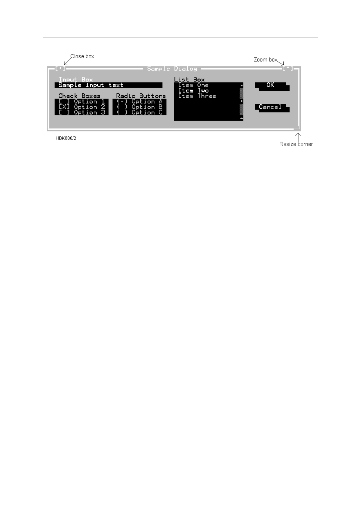
OPERATING MANUAL
INSTRUMENT LANDING SYSTEM
NORMARC 7013
Figure 5-1 A sample dialog box.
5.3.3.1 Action buttons
This dialog box has two standard buttons: OK and Cancel. If you choose OK, the choices in
the dialog box are accepted; if you choose Cancel, nothing changes and no action takes
place, and the dialog box is put away. You can press F1 to open a Hel p window for this dial og
box. Esc is always a keyboard shortcut for Cancel (even if no Cancel button appears).
If you are using a mouse, click the dialog box button you want. When you are using the keyboard, press Alt and the highli ghted letter of an item t o activate it . For example, ALT+O selects
OK because the O in OK is highlighted. Press Tab or Shift+Tab to move forward or back from
one item to another in a dialog box. Each element is highlighted when it becomes active.
In this dialog box, OK is the default button , which means you need only pres s Enter to choose
that button. (On monochrome systems, arrows indicat e the default; on color monitors, default
buttons are highlighted.) Be aware that tabbing to a button makes that button the default. You
can then press Space to choose that button.
5.3.3.2 Radio buttons and check boxes
Radio buttons are like car radio buttons. They come in groups, and only one radio button in
the group can be on at any one time. To choose a radio button, cli ck it or it s te xt. Fro m the keyboard, select Alt and press the highlighted letter (if any), or press Tab until the group is highlighted and then use the arrow keys to choose a particular radio button. Press Tab or
Shift+Tab again to leave the group with the new radio button chosen.
Check boxes differ from radio buttons in that you can have any n umbe r of check boxes
checked at any time. When you select a check box, an x appears in it to show you it's on. An
empty box indicates it's off. To change the status of a check box, click it or its text, press Tab
until the check box is highlighted and then press Spacebar, or select Alt and the highlighted
letter (if any).
If several check boxes apply to a topic, they appear as a group. In t hat case, tabbing moves to
the group. Once the group is selected, use the arrow keys to select the item you want, and
then press Spacebar to check or uncheck it. On monochrome monitors, the active check box
or group of check boxes will have a chevron symbol (>>) to the left and right. When you press
Tab, the chevrons move to the next group of check boxes or radio buttons.
Remote Maintenance and Monitoring ©1999 Navia Aviation AS
5-6
21833-3.4
Page 45

OPERATING MANUALNORMARC 7013
INSTRUMENT LANDING SYSTEM
5.3.3.3 Toggles
Toggles let you select one setting out of a group defined settings. They are similar to Radio
buttons (chapter 5.3.3.2); except that only the selected setting is displayed. You select other
settings by clicking on the text showing the toggle setting, or by pressing the space bar.
5.3.3.4 Input and list boxes
Input boxes let you ty pe in t ext . Most bas ic te xt-edi ting k eys work in the text b ox ( for exa mple,
arrow keys, Home, End, and Ins). If you continue to type once you reach the end of the box,
the contents automatically scr oll. If ther e is more text than what shows in the box, arrowheads
appear at the end. You can click the arrowheads to scroll or drag the text.
If an input box has a down-arrow icon to its right, there is an associated history list. Click the
down arrow icon, or press the down arrow key to display the list. You will find text you typed
the last few times you used the input box. Press Enter to choos e an item from this li st. You can
also edit an item in the history list. Press Esc to exit from the history list without making a
selection.
A final component of many dialog boxes is a list box, which lets you scr oll through and select
from variable-length lists (often file names) without leaving a dialog box. If a blinking cursor
appears in the list box and you know what you are looking for, you can type the word (or the
first few letters of the word) and the ILS Dat a Sampler will search for it.
You make a list box active by clicking it or by choosing the highlighted letter of the list title (or
press Tab until it's highlighted). Once a list box is displayed, you can use the scroll box to
move through the list or press the arrow keys on the keyboard.
5.4 Configuring the RMM system
This chapter describes how to configure the RMM system. The configurat ion settings cov ered
in this chapter does not affect the operation of remote IL S systems in any manner. It applies to
the “PC part” of the system only.
The configuration dialogs is accessed via the Options menu. The following sub-chapters covers each of the menu items on this menu.
5.4.1 Communications setup
The software allows you to connect the modems to two of four communications port s; COM1 COM4, with configurable IRQ's for COM3 and COM4. The ILS st a tion may al so be connect ed
directly to the PC by the use of a null modem cable.
The communication with the ILS is done with the use of a Channel construct. In the stati on
setup for an ILS station one selects a Channel in which the communication with the remote
ILS shall flow . Each channel is then associated with a specific set of configurable communication settings.
Choosing Communications setup brings up the following dialog
©1999 Navia Aviation AS 21833-3.4 Remote Maintenance and Monitoring
5-7
Page 46
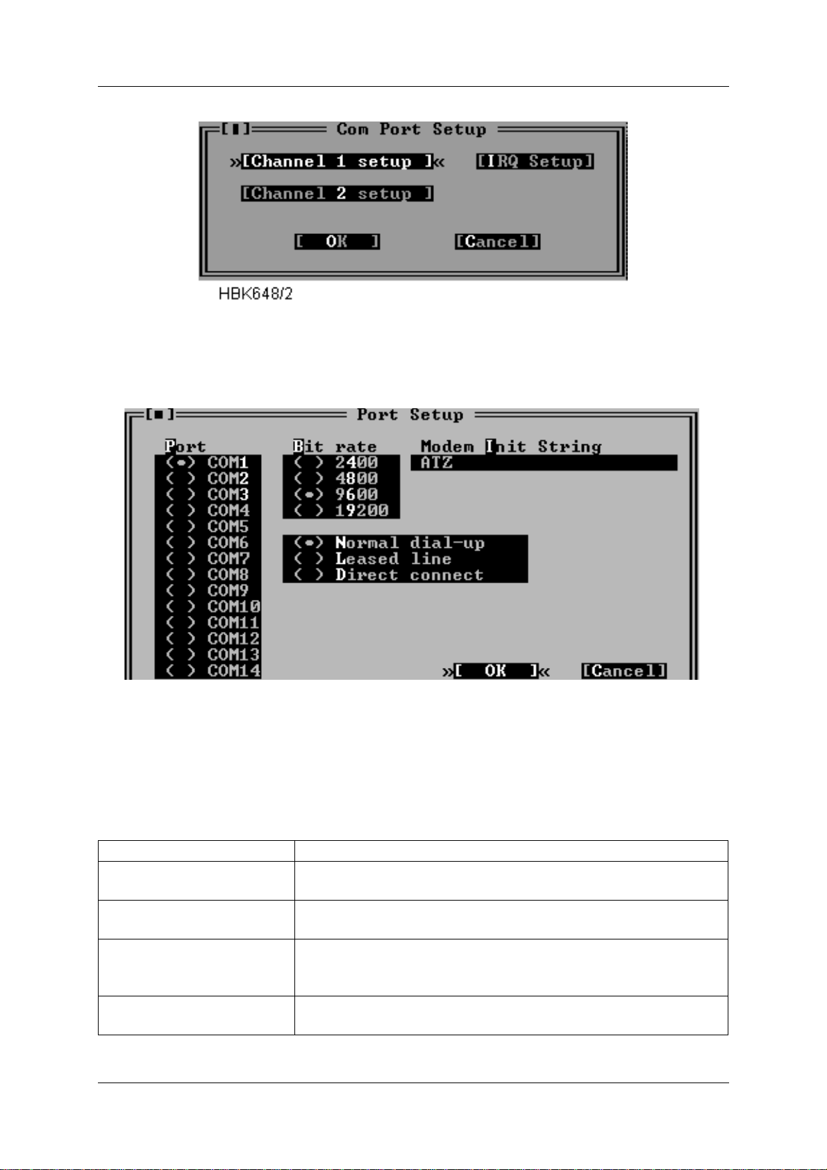
OPERATING MANUAL
INSTRUMENT LANDING SYSTEM
NORMARC 7013
.
Figure 5-2 Com port setup dialog
Selecting one of the Channel setup buttons opens up a dialog like Figure 5-3 shows.
Figure 5-3 Channel setup dialog
Note: DOS version also has the “Modem hangup String” and “Use DTR to hangup” fields in
this window. In the Win95/NT version DTR will always be used to hangup the modem.
The items in this dialog has the following purposes.
Item Purpose
Port Specifies the serial communications adapter to which the
modem or ILS is connected.
Bit rate Specifies the bit rate to use when communicating with the
modem or ILS.
Use DTR to hang-up Select this if the software should use the DTR line instead of t he
"Modem hang-up string" to make the modem hang up. This is
faster and safer than using the Modem hang-up string.
Direct connect Select this if the PC is connected to the ILS via a null modem
cable.
Remote Maintenance and Monitoring ©1999 Navia Aviation AS
5-8
21833-3.4
Page 47
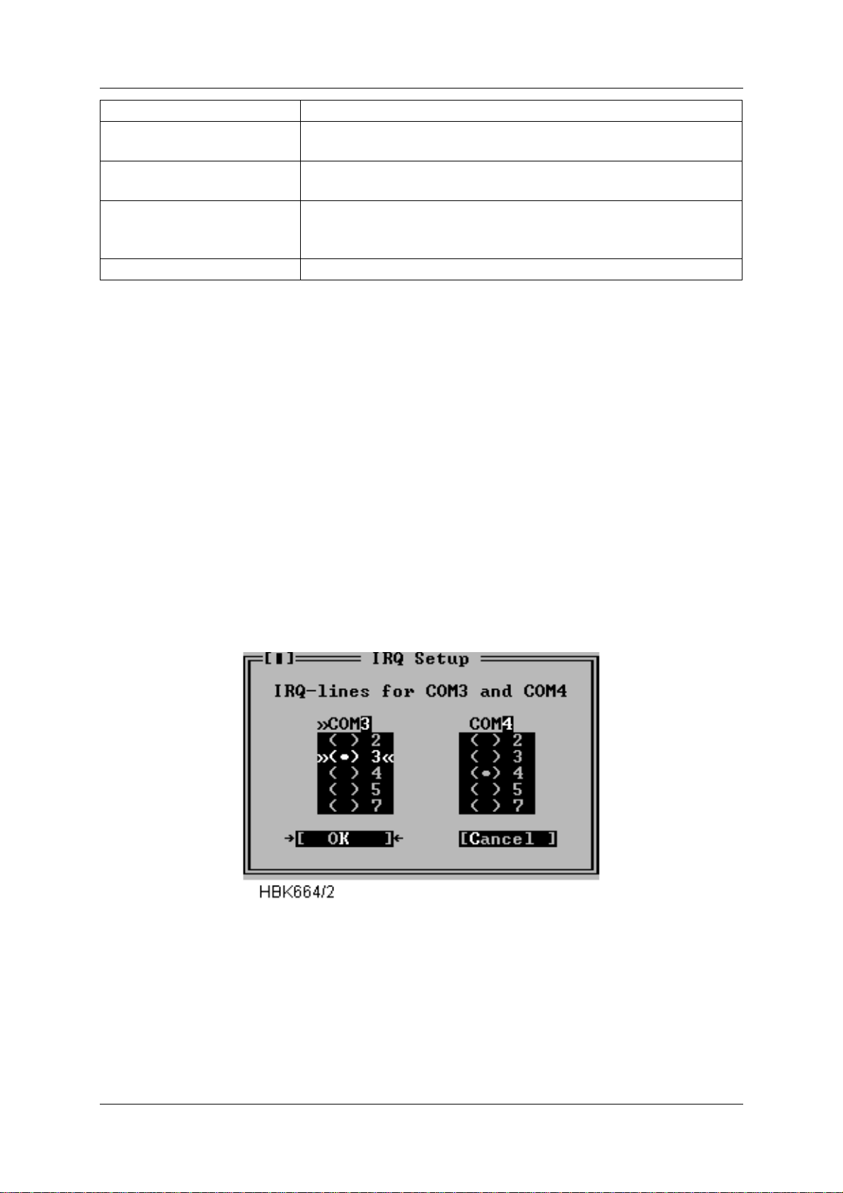
OPERATING MANUALNORMARC 7013
INSTRUMENT LANDING SYSTEM
Item Purpose
Leased line Select this if the PC is connected to the ILS via dedicated
leased line modems.
Normal dial-up Select this if the PC shall connect the ILS via modem on a pub-
lic telephone network.
Modem Init Stri ng This string will be sent to the modem before each dialing proc-
ess starts. The default is ATZ, which performs a software reset
of the modem.
Hang-up String Command to make the modem hang up the phone.
Table 5-3 Channel setup operations.
Modem configuration
5.4.1.1 Close Connecti on
Selecting the "Use DTR to hang-up" is recommended, as this method for closing the connection is both safer and faster than the "+++" escape sequence (Hang-up string). Note that the
modem must be configured with the AT&D2 command for the "Use DTR to hang-up" method
to work (some modems do not include this command in their default initiation).
5.4.1.2 Recommended init-strings
Refer to the Technical notes at the end of this chapter for information on how to set up the
modems on different types of connection.
5.4.2 IRQ setup
Selecting the IRQ setup button in the Com port setup dialog opens the following dialog.
Figure 5-4 IRQ setup dialog
This dialog allows alternate IRQ selections for COM3 and COM4.
NOTE
The Win95/NT version does not have this dialog, as these settings are handled at the
operating system level.
5.4.3 Printer setup
©1999 Navia Aviation AS 21833-3.4 Remote Maintenance and Monitoring
5-9
Page 48
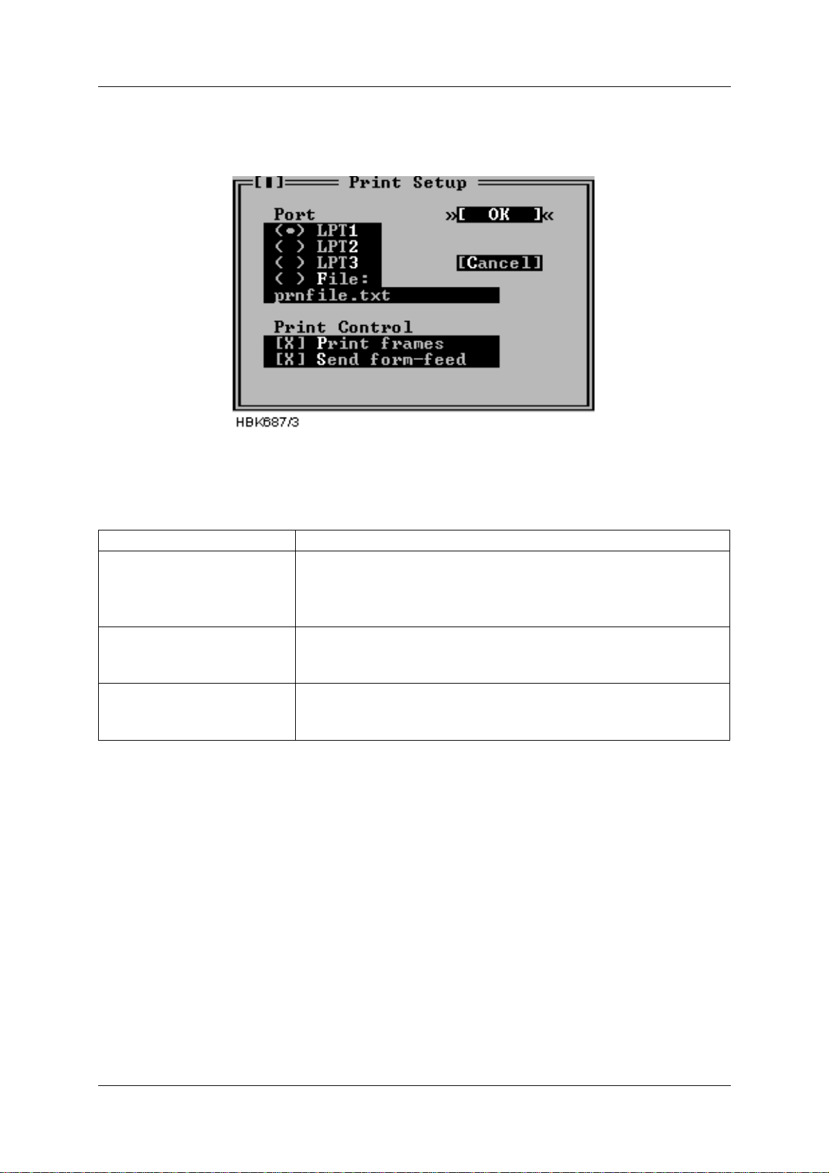
OPERATING MANUAL
INSTRUMENT LANDING SYSTEM
NORMARC 7013
The Printer setup dialog contains options for an optionally connected printer. The dialog is
shown below.
Figure 5-5 Print setup dialog
The purpose of each field in the dialog is described below.
Item Purpose
Port Determines the printer port to use for the printing.
If “File” is selected the output will be sen t to the file specified in
the string input field. The file will be created in the “Log directory” for the current stat ion (see 5.5).
Print frames Allows enabling/disabling the printing of special frame charac-
ters. Uncheck this checkbox i f your pri nter does n ot support the
PC-8 bit character set.
Send form-feed Allow for sending a form-feed (ASCII 12) character to the pr inter
following each print-out. The extra form-feed is required by
most laser printers.
Table 5-4 Print setup operations.
To print the report, select File|Print report.
5.4.4 Preferences
The Preferences dialog allows the user to set general program preferences
Remote Maintenance and Monitoring ©1999 Navia Aviation AS
5-10
21833-3.4
Page 49
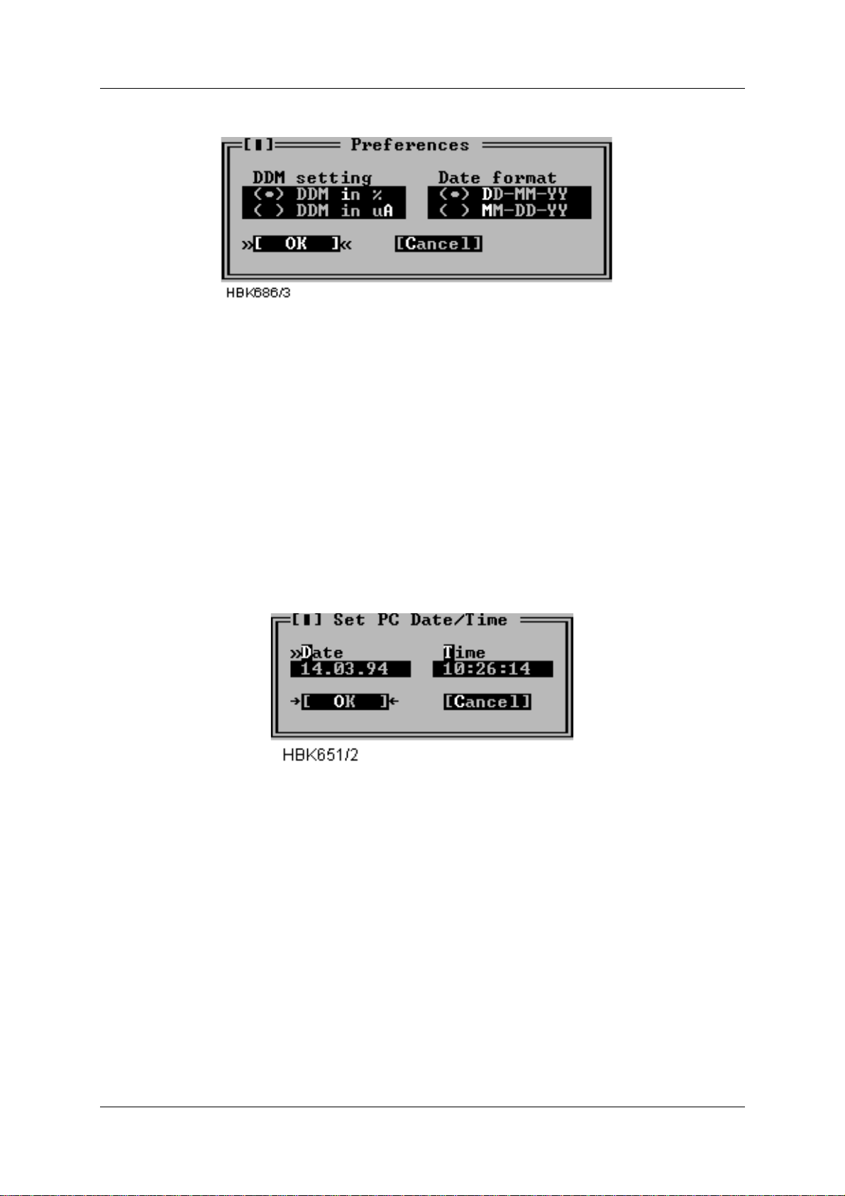
OPERATING MANUALNORMARC 7013
INSTRUMENT LANDING SYSTEM
.
Figure 5-6 Preferences dialog
The DDM setting applies to all user input and all screen or printer output of DDM measurements. Selecting % means that input/output is in percent, likewise, select ing uA results in
micro ampere input/output.
The date format field selects day-month-year or month-day-year display of ti me.
5.4.5 Toggle video mode
This menu selection toggles the current video mode between 25 lines and 43/50 lines.
5.4.6 Set date/time
To set the date and time of the PC, select Set date/time from the Options menu. A dialog as
show next is shown.
Figure 5-7 Set date/time dialog
In the Date field, enter the current date in day.month.year format if DD.MM.YY is selected in
the Preferences dialog ( Figure 5-6) . Els e enter t he date in MM.DD.YY for mat. In t he time fi eld,
enter the current time of day in standard 24 hour format.
5.5 Setting up ILS stations
Before connecting to an ILS station the st ation must be added to the “station list”. Some information about each station must also be entered, e.g. the number to dial to connect to the station. This chapter describes how to set up ILS stat ions.
Selecting the ILS | Station list menu command brings up a dialog like the one shown below.
©1999 Navia Aviation AS 21833-3.4 Remote Maintenance and Monitoring
5-11
Page 50
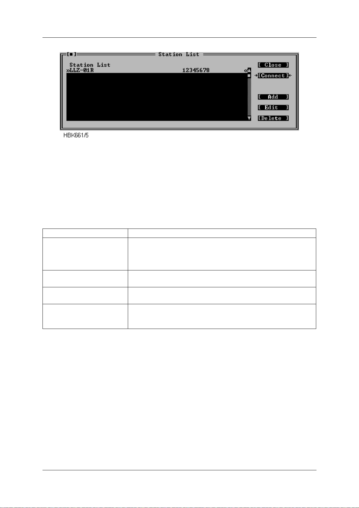
OPERATING MANUAL
INSTRUMENT LANDING SYSTEM
NORMARC 7013
Figure 5-8 Station list dialog.
This dialog contains a list showing the name and number of the configured stations. Use the
scroll bar to the left of the list to scr oll or user the up/down arrow keys. If the selected Channel
for a station is a “Direct connect” channel, the number field will show DIRECT/CHx. Up to 50
stations may be configured.
The following table describes how use this dialog.
To accomplish this Do this
Change the configuration for
a specific station.
Select the station from the list, and press the Edit button. You
can also press ENTER, when the desired stati on is hi ghlight ed.
Double-clicking the desired station also activates the Edit function.
Add a new station to the list Press the Add button, or edit an empty name/number line from
the list.
Delete a station Select the station you want to delete and press the Delete but-
ton. You may also press Del on your keyboard.
Connect to the station
Press the Connect button.
(see the Displaying measurements chapter)
Table 5-5 Station list operations.
When you have selected Add or Edit from the above dialog, another dialog appears. This dialog is shown in Figure 5-9.
Remote Maintenance and Monitoring ©1999 Navia Aviation AS
5-12
21833-3.4
Page 51
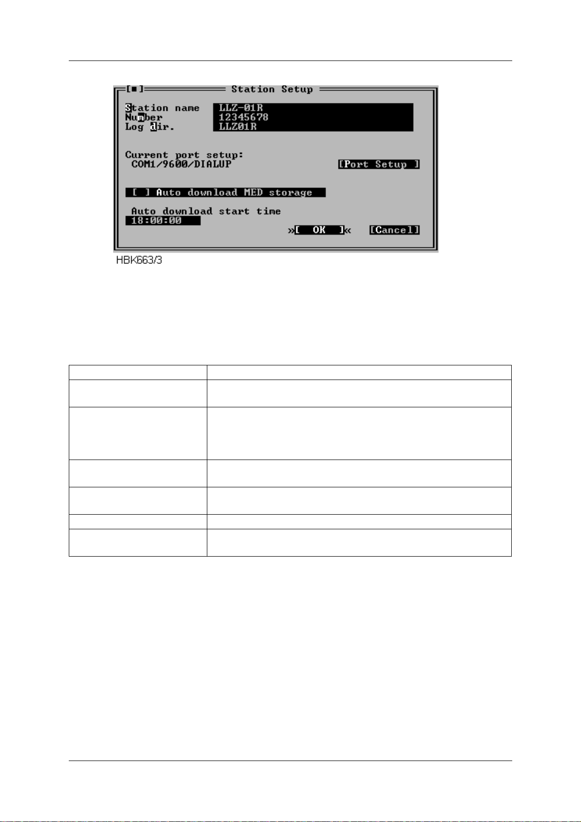
OPERATING MANUALNORMARC 7013
INSTRUMENT LANDING SYSTEM
Figure 5-9 ILS Station setup dialog
The table below describes the meaning of each field in the ILS Station setup dialog.
Use field To specify
Station name A name for the ILS station. Holds up to 20 characters. This
name is saved in the log files you create.
Number The telephone number of the ILS station. This string is passed
directly to the modem, meaning that special chara cters like ',' or
other characters can be included if the modem understands
them.
Log dir. name The name of the directory where downloaded measurements
shall be stored. The directory is made if it do not exist.
Auto download MED
storage
Whether or not the medium time periodic storage should be
downloaded automatically each day.
Start time The time of day to start the automatic MED download.
I/O channel Which I/O channel to use when connecting to this station.
(See the Communications setup chapter)
Table 5-6 ILS station setup operations.
5.6 Connecting to an ILS station
To connect to an ILS station the station must first be added to the Station List, as descri bed in
chapter 5.5. When this has been done, just press the “Connect” button in the ILS St ation List
dialog. The software will try to make a connection to the station. Once a connection has been
established you will be prompted to enter your use rname and passwords. You enter this information in the dialog box shown in Figure 5-10.
©1999 Navia Aviation AS 21833-3.4 Remote Maintenance and Monitoring
5-13
Page 52
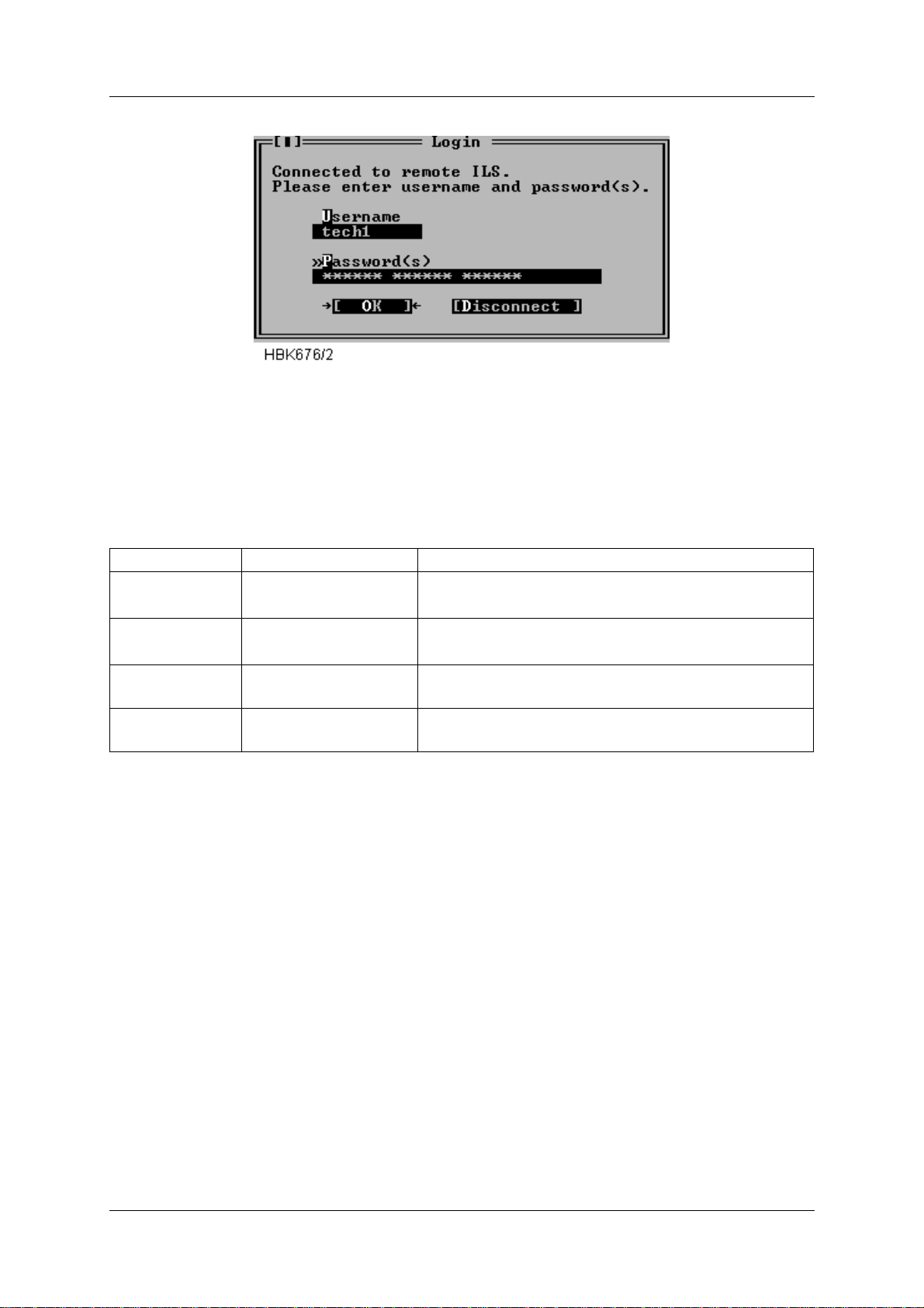
OPERATING MANUAL
INSTRUMENT LANDING SYSTEM
Figure 5-10 Login dialog box
Your assigned access level depend on the number of passwords and the username entered.
Different passwords must be separated with a space character. The following table outlines
the access level properties, and how to gain them. Increasing access levels adds more
access rights, and retai n ing the rights for the lower access levels.
NORMARC 7013
Access level You enter Access rights
1 your username and 1
password
2 your username and 2
passwords
3 your username and 3
passwords
MASTER username MASTER
and 3 passwords
Table 5-7 Login access rights.
When you have entered correct login i nformation and pr essed the OK butto n, the pr ogram will
start to retrieve ILS configuration data. Windows that was open the last time you was connected to the ILS will automatically be opened when the ILS configu ration has been received.
If you enter invalid login information the ILS will not grant you access rights to the ILS. The
software will display a message telling you what went wrong, and let you perform another
login attempt. You have three attempts. If all attempts are used without success the ILS will
disconnect and not allow more login attempts for 3 minutes.
When the program has received the configura tion dat a, th e ILS configur ation will be display ed
in a window in the upper lef t corne r of the deskt op area. This wi ndow will be re ferr ed to as the
“Link” window. Figure 5-11 shows a typical Link window.
Read all measurements/status and show all settings,
and download.
Change front panel settings and change settings in
the “Ident and mod. switches” window.
Change all settings (except user administration)
Set up new users and change passwords.
Remote Maintenance and Monitoring ©1999 Navia Aviation AS
5-14
21833-3.4
Page 53
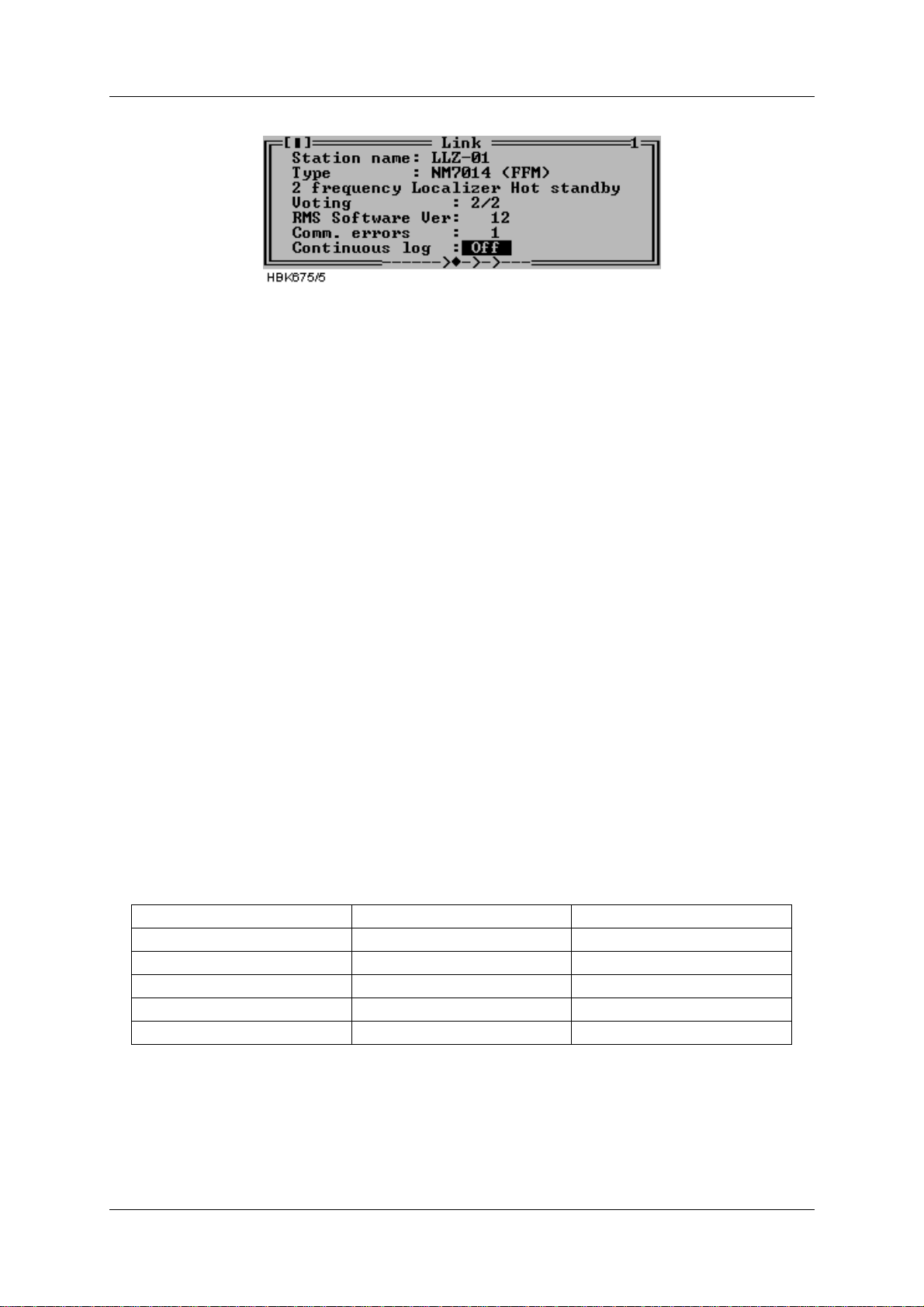
OPERATING MANUALNORMARC 7013
INSTRUMENT LANDING SYSTEM
Figure 5-11 A typical Link windo w
5.6.1 Shutting down the connection to an ILS
To shut down an ILS connection, close the Link window for the connection you want to shut
down. For information on how to close a window, see Table 5-2.
Do not close the windows you want reopened the next time you connect to this ILS station.
5.6.2 Baud rate recommendations
When connecting to the ILS at 9600 bps, Remote port 2 or Local port on the ILS should be
used. For performance reasons, remote port 1 should not be used at 4800 and 9600 bps. This
will affect the response times of the Local RMS front panel as well as message handling on
the other RS-232 ports.
5.7 Monitor measurements and status
5.7.1 General
The functions described in this and the following chap ters are accessed via the ILS|Measurement sub-menu.
The windows described here will automatically be update d with new measurements as long
as the windows remain open.
The monitors signal the state of each par ameter. For analog measurements, the stat es wi ll b e
displayed by a character code preceding the measurement and by the col or of the displayed
number.
State Character code Colour code
Normal (None) (Black)
Raw warning w Yellow
Delayed warning W Yellow
Raw Alarm a Orange (light red)
Delayed Alarm A Red
Table 5-8 Monitor codes.
For digital measurement only two states are defined; OK and ERROR. The ERROR string is
shown in red, while the OK string is shown in black.
5.7.2 Monitor window
©1999 Navia Aviation AS 21833-3.4 Remote Maintenance and Monitoring
5-15
Page 54
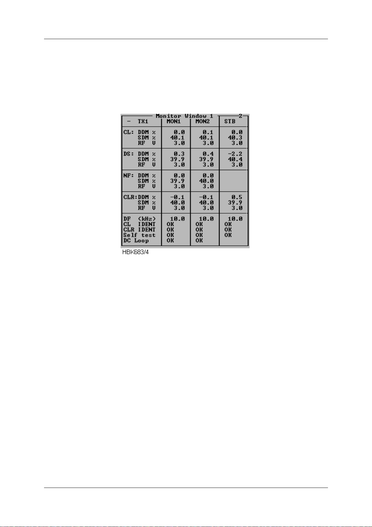
OPERATING MANUAL
INSTRUMENT LANDING SYSTEM
NORMARC 7013
To display the parameters shown in the window below select the ILS|Measurements|Monitor
Window 1 menu item. This window displays the standard monitor parameters (DDM, SDM
and RF-level) for each of the monitor channels (Course line, Displacement Sensitivity, Near
field and Clearance Transmitter (2-freq. systems)). In addition, Difference Frequency (2freq.systems), DC-loop and Ident in formation are di splayed. The res ult of the cont inuous monitor self test is also shown.
Figure 5-12 Monitor window
The DC loop status shown in this window will be OK if all the DC loop readings are within the
warning limits, else ERROR is displayed (DC loop r eadings for each loop is displayed in Monitor window II).
5.7.3 Additional monitor parameters window
Selecting ILS|Measurements|Monitor 2 bri ngs up the fol lowing window. This window shows
secondary monitor parameters.
Due to the nature of the monitor self test signals, the values wi ll toggle between alarm and
normal. If one of these erroneous te st signals f ails to generate alar m, a self test erro r will be i n
Monitor Window 1. The CL/CLR MORSE parameters shows the modulation level of the ident
signal. No activity on this signal for the time peri od specified in the ident delay setting, will
result in an IDENT warning in Monitor Window 1.
Depending on the antenna system installed, up to 4 DC-loops can be active. The DC LOOP
parameter in Monitor Window 1 shows accumulated status of the 4 DC-loops.
Remote Maintenance and Monitoring ©1999 Navia Aviation AS
5-16
21833-3.4
Page 55
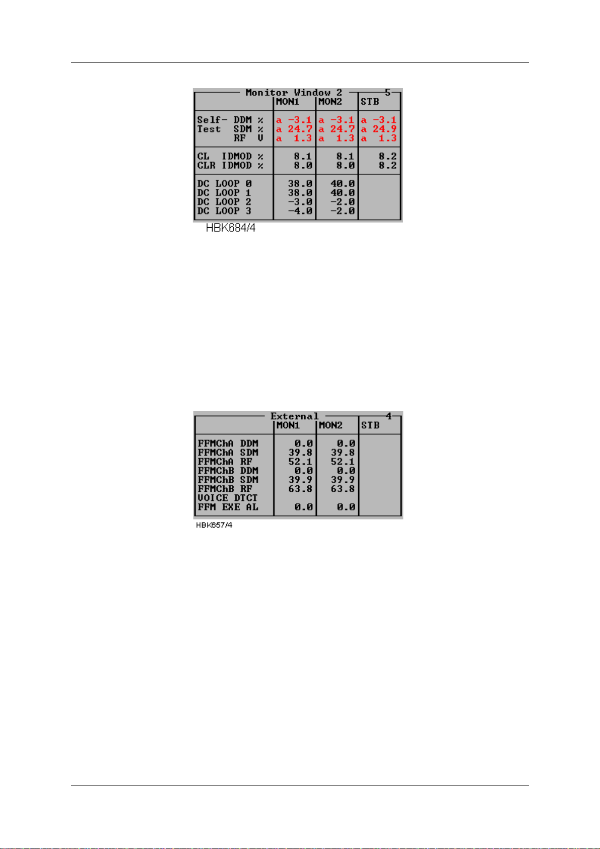
OPERATING MANUALNORMARC 7013
INSTRUMENT LANDING SYSTEM
Figure 5-13 Additional monitor paramet ers window
5.7.4 External paramet e rs window
Selecting ILS|Measurements|External brings up t he following window. This window shows the
measurements on the external channels. The NM 70xx can provide executive monitoring of
signals from external equipment, defined by the user (option).
For external channels that are not used, no measurement field will be shown (e.g. the standby
measurement field will be shown (e.g. the st andby measurements in Figure 5-14)
Figure 5-14 External parameter s window
5.7.5 Maintenance monitor window
Selecting ILS|Measurements|Maintenance brings up the window shown below. The maintenance warning parameters are displayed in groups corresponding to the modules on which
they are measured. A separate group consists of the main power supplies and current measurements. In this way, the origin of a maintenance warning can easily be deduced.
If one maintenance parameter on a module is in warning status, the module to which it
belongs is given the same status. Therefore, it can be easily determined the maintenance
warning status of the system by looking at the top window (Figure 5-15) only.
The following table shows the defined status codes.
©1999 Navia Aviation AS 21833-3.4 Remote Maintenance and Monitoring
5-17
Page 56
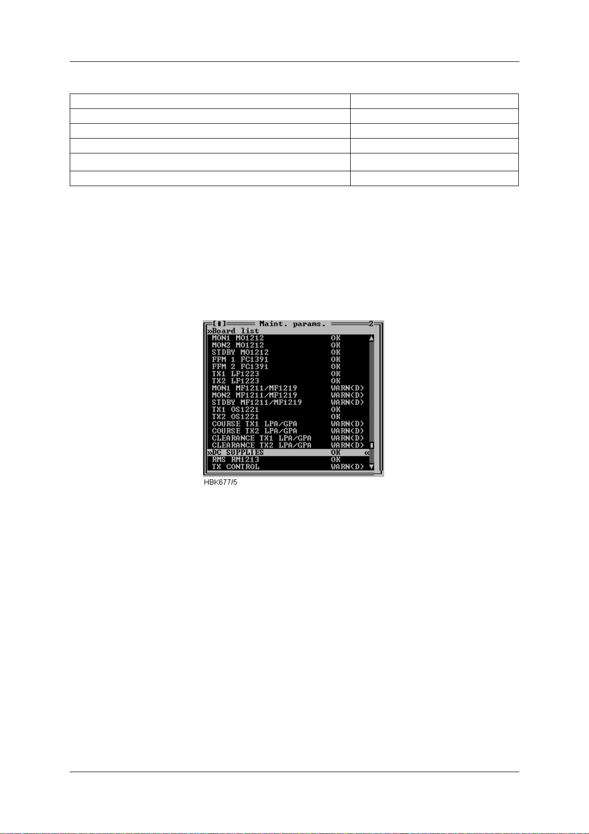
OPERATING MANUAL
INSTRUMENT LANDING SYSTEM
NORMARC 7013
Status Status code
All parameters OK OK
Raw warning on at least one param. WARN (R)
Delayed warning on at least one param. WARN (D)
Internal I
2
C error on at least one param.
ERROR
No measurements applicable N/A
Table 5-9 Status codes.
Digital parameters are displayed as outlined in the above table. Analog parameters are displayed with the same character and color codes as the monitor measurements.
By selecting a board on the list and double-c licking it or pressin g Enter opens another window
which displays the status/measurements on that specific board.
Figure 5-15 Maintenance monitor window
The following figures show the available status/measurement windows.
Remote Maintenance and Monitoring ©1999 Navia Aviation AS
5-18
21833-3.4
Page 57
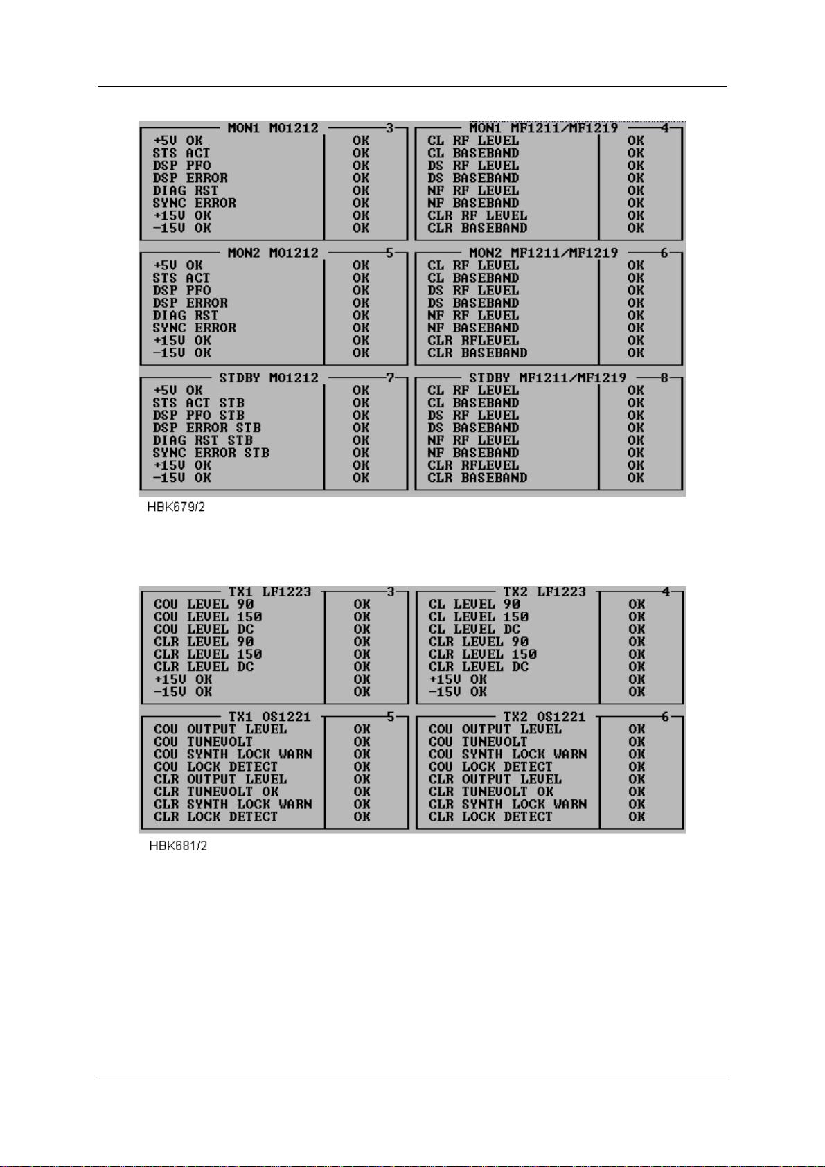
INSTRUMENT LANDING SYSTEM
OPERATING MANUALNORMARC 7013
Figure 5-16 Monitor maintenance parameters
Figure 5-17 TX maintenance parameters
©1999 Navia Aviation AS 21833-3.4 Remote Maintenance and Monitoring
5-19
Page 58
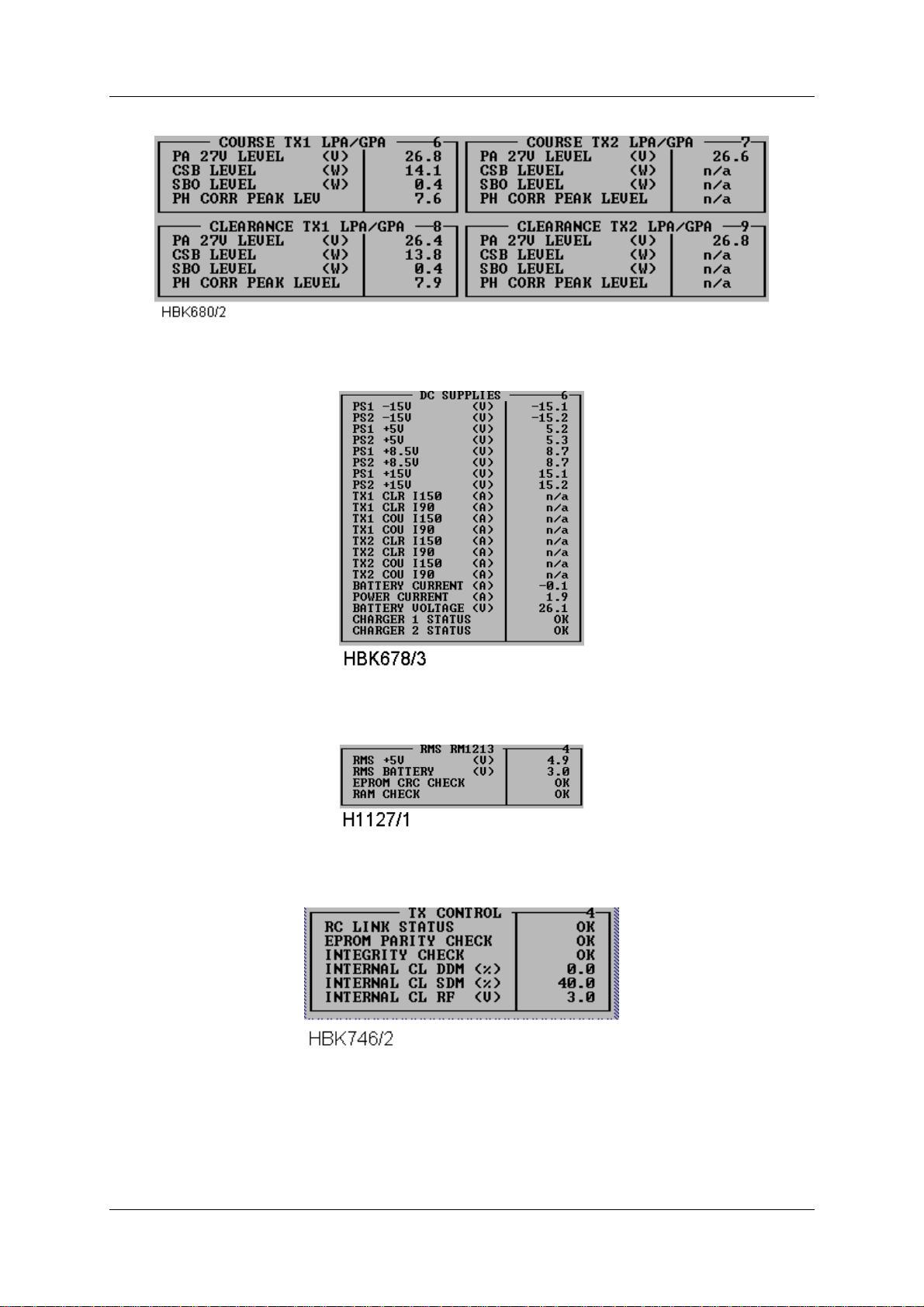
OPERATING MANUAL
NORMARC 7013
INSTRUMENT LANDING SYSTEM
Figure 5-18 PA maintenance parameters
Figure 5-19 DC-Supplies maintenance parameters
Figure 5-20 RMS maintenance parameters
Figure 5-21 TX Control maintenance parameters
5.7.6 User parameters window
Selecting ILS|Measurements|User brings up the window shown below. This window shows
the user defined input/output states and measurements.
Remote Maintenance and Monitoring ©1999 Navia Aviation AS
5-20
21833-3.4
Page 59
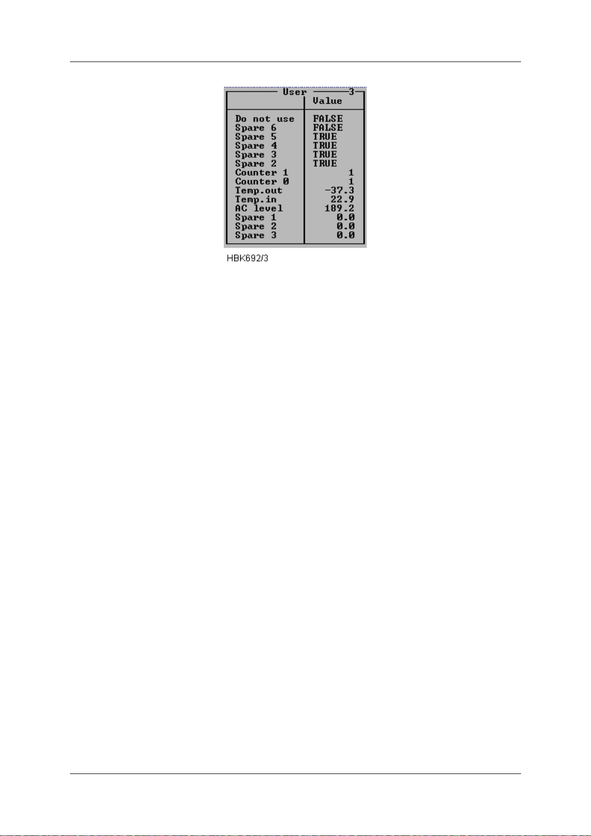
OPERATING MANUALNORMARC 7013
INSTRUMENT LANDING SYSTEM
Figure 5-22 User parameters window (sample configuration).
If a digital user paramet er is defined as a out put and you have at least acces s level 2, you can
change the output value by changing the state of the corresponding toggle in this window.
5.8 Monitor settings
The functions described in this and the following sub-chapter are accessed via the ILS|Monitor settings sub-menu.
The current access level determin es which fun cti ons wil l be avai lable. If a functi on is not avai lable because of to low access level, the function will not be possible to activate.
All access levels allow the currently stored sett ing to be displayed; but in order to change a
setting an access level of at least 3 is required.
5.8.1 Limits Monitor 1&2
When the ILS|Monitor settings|Limits Monitor 1&2 menu option is sel e cted a window showing
the currently configured monitor 1 and 2 alarm and warning limits is display ed. A window with
sample data is displayed below.
©1999 Navia Aviation AS 21833-3.4 Remote Maintenance and Monitoring
5-21
Page 60
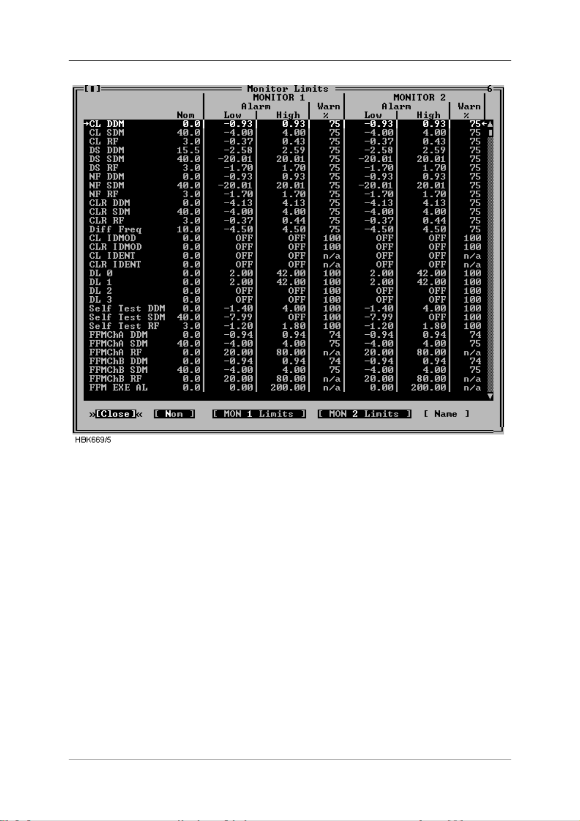
OPERATING MANUAL
NORMARC 7013
INSTRUMENT LANDING SYSTEM
Figure 5-23 Monitor 1&2 limits window
The alarm limit field will show “OFF” if the alarm limit is equal to the maximum or minimum
value.
The warning limit field for CL IDENT, CLR IDENT and external channels (i.e. FFM RF and
VOICE) will show “n/a” as the warning limits for these parameters is not def ined as a percentage of the alarm limits.
The “MON 1 Limits” and the “MON 2 Limits” buttons will only be displayed for access
level 3 and master user access level.
In order to change the alarm and/or warning limits for a specific parameter; first select the
parameter in the list box, then selec t the “MON 1 Limits” butt on or the “MON 2 Limits” button if
you want to change either monitor 1 or monitor 2 alarm/warning.
When one of the above mentioned buttons is selected a dialog similar to the one below is
opened. In this dialog one may enter new alarm limits and warni ng limit for the currently
selected parameter. The alarm limits is always relative to t he nominal value. The warn ing limit
is always entered in percent of the selected alarm limit.
If the Symmetric button is pressed the alarm limit is entered as a value which is symmetric
around the nominal value; hence only one alarm limit wi ll have t o be ente red in the sy mmetric
Remote Maintenance and Monitoring ©1999 Navia Aviation AS
5-22
21833-3.4
Page 61
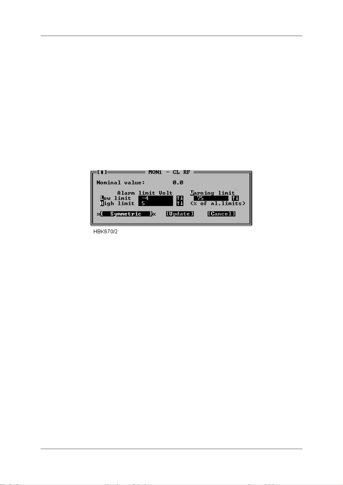
OPERATING MANUALNORMARC 7013
INSTRUMENT LANDING SYSTEM
mode.
The arrowheads after each input field in this dialog can be clicked on to increase or decrease
the displayed limit value. Hold down Shift to increment/decrement by a larger value. The up
and down arrow keys may be used instead of the mouse.
Due to the digital represent a tion of t he alarm and warning limits, the entered value is rounded
to the nearest 12-bit digital value. The actual stored value, which is read back to the dialog
box, can therefore differ slightly from the entered value.
The text OFF may be entered in alarm limits field to inhibit low, high or any alarms on the current monitor parameter. If OFF is entered, one would normally enter 100 (%) in the warning
field, in order to also inhibit warning indications. For parameters where the warning limits is
not in % of the alarm limits , large negat ive and pos itive numbers must be entered to i nhibit t he
warning. See Appendix B for recommended values.
Figure 5-24 Monitor parameter input dialog
The NAME button is used to change the parameter name. This applies to the ext ernal channels only.
Refer to appendix B for the factory default values o f all monitor parameters.
5.8.2 Limits Standby monitor
When the ILS|Monitor settings|Limits Stdby monitor menu option is selected a window showing the currently configured standby monitor alarm and warning limits is displayed. This window is used in the same way as the Monitor 1&2 limits window, described above.
5.8.3 Delays
Selecting ILS|Monitor settings|Delays brings up the Monitor Delays window, shown below.
The NM70xx is configured with three separately adjustable delays: Normal, Near Fiel d, Ident
and Far Field Monitor. This window displays the currently configured Monitor 1&2 (equal
delays) and standby monitor delays. To change a delay; first select the desired parameter on
the list and then press the “Mon 1 and 2” button if the delay for Monitor 1 and 2 should be
altered, else press the “Stdby” button for a standby monitor delay change.
©1999 Navia Aviation AS 21833-3.4 Remote Maintenance and Monitoring
5-23
Page 62
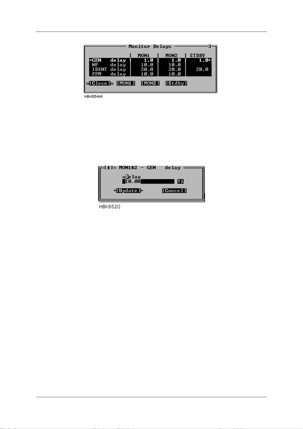
OPERATING MANUAL
INSTRUMENT LANDING SYSTEM
NORMARC 7013
Figure 5-25 Monitor delays window
A standby column will be shown if the system is equipped with a standby monitor. The resolution of the delay parameters is 1/10 second.
Once the “Mon 1 and 2” or the “S t dby” bu tton has be pressed a n input dialog l ike the one show
below is opened. Enter the desired delay in the field, or use the up and down arrows to increment/decrement the current value. When the “Update” button is selected, the ILS will be
updated.
Figure 5-26 Delay input dialog
Valid input range in this window is 0.4 to 102.3 seconds. The tot al changeover-shutdown
delay will be two times this value. See Appendix B for recommended values.
5.8.4 Limits Maintenance monit or
When the ILS|Monitor settings|Analog maintenance limits or Digital maintenance limits menu
item is selected a window showing the currently configu red anal og/digital maintenance monitor warning limits is displa yed. Windows with sampl e data is di splayed below. The board name
is shown idented to the left. The maintenance parameters is show after each board name.
For analog parameters the “Low” and “High” columns sh ows the low and high warning limits.
For digital parameters a single column show the “normal state” for the parameter. If the
parameter state is not equal this state a maintenance warning will be generated by the ILS
RMM software. If no warning is wanted for a parameter the columns will display “O FF”.
See Appendix B for factory default settings.
Remote Maintenance and Monitoring ©1999 Navia Aviation AS
5-24
21833-3.4
Page 63
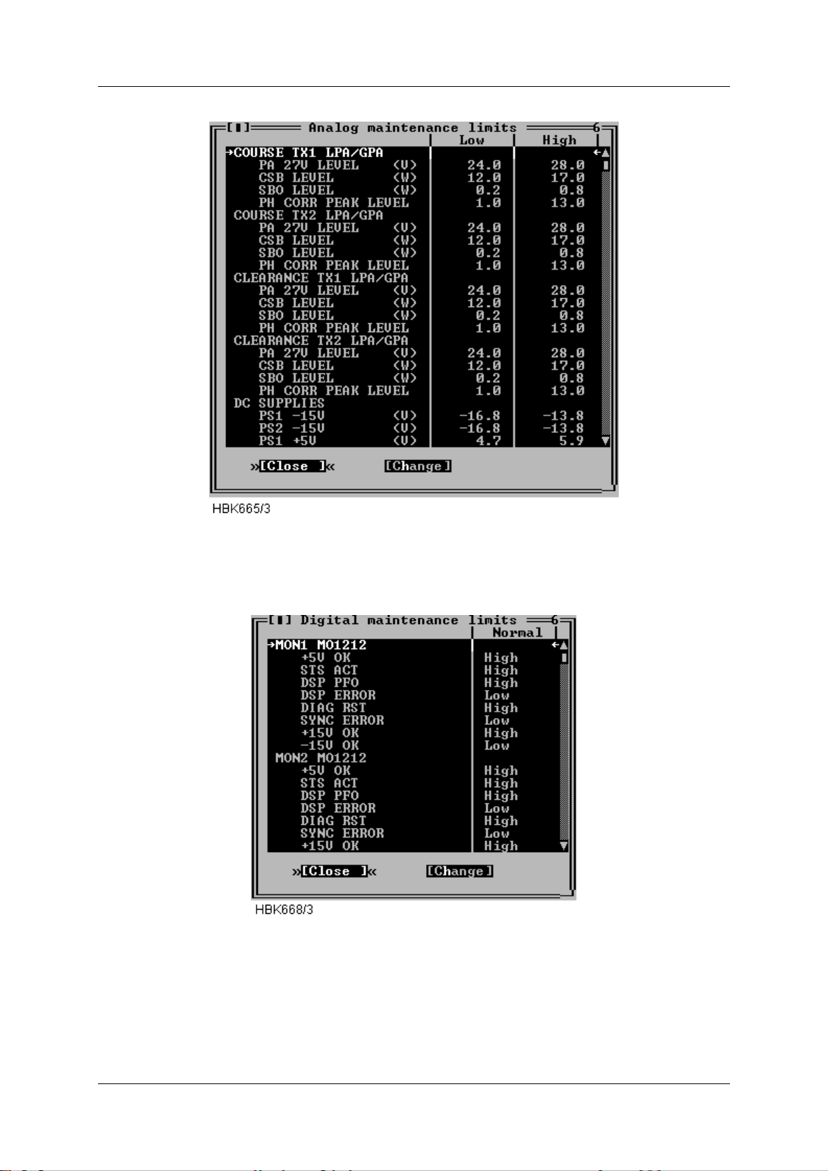
INSTRUMENT LANDING SYSTEM
OPERATING MANUALNORMARC 7013
Figure 5-27 Analog maintenance monitor limits window
This list is scrollable, all defined parameters are listed in the Maintenance monitor chapter.
Figure 5-28 Digital maintenance monitor limits window
This list is scrollable, all defined parameters are listed in the Maintenance monitor chapter.
To change a warning limit; first selec t the desired p arameter on the list and p ress the “Change”
button. Depending on the type (digit al/analog) of the dialog, one of t he dialogs shown next wi ll
©1999 Navia Aviation AS 21833-3.4 Remote Maintenance and Monitoring
5-25
Page 64
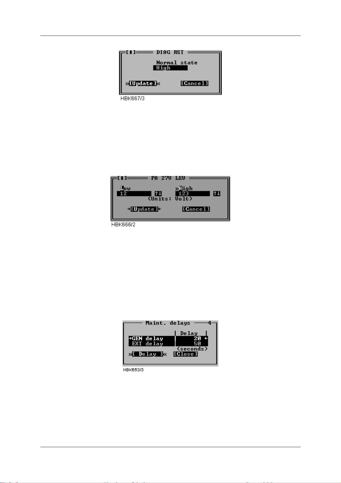
OPERATING MANUAL
INSTRUMENT LANDING SYSTEM
NORMARC 7013
be opened.
Figure 5-29 Input dialog for digital maintenance parameters
To change the setting for a digital parameter cl ick in the normal st ate field or use the space ba r
to toggle. The normal state field will toggle between Low, High and OFF. The settings for the
CHARGER 1 STATUS and CHARGER 2 STATUS parameters is On and Off.
Press the Update button when the desired state is shown.
Figure 5-30 Input dialog for analog maintenance parameters
To change the setting for a analog parameter, type in the wanted low and high warning limits
in the corresponding fields. Then press the Update butt on.
5.8.5 Delays Maintenance monitor
To display or change the maintenance monitor delay parameters, select the ILS|Monitor settings|Delays maintenance monitor menu item. The window shown below will be displ a yed.
The operation of the window is similar to the operation of the Monitor delays window .
Figure 5-31 Maintenance delay window
The resolution of the maintenance delay parameters is 1 second. Valid input range is 1 to
1023 seconds.
5.8.6 Analog user parameters
Selecting ILS|Monitor sett ings|Analog user para meters opens the window i n Figure 5- 32. This
Remote Maintenance and Monitoring ©1999 Navia Aviation AS
5-26
21833-3.4
Page 65
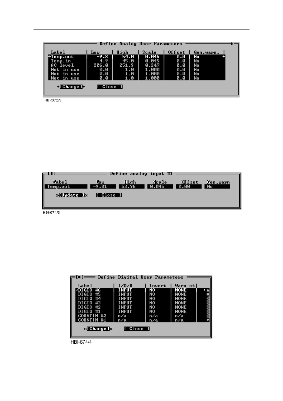
OPERATING MANUALNORMARC 7013
INSTRUMENT LANDING SYSTEM
window shows the current settings for the analog user parameters.
Figure 5-32 Analog user parameters definiti ons
The following definitions c an be made for t he analog user p arameters: Name, lower and upper
warning limits, and scale and offset constants for conversion to engineering units. There is
also a field for enabling/disabling gener ation of a maintenance warning.
To change the settings for a parameter, select the parameter on the lis t and press the
“Change” button. This brings up the dialog shown below.
Figure 5-33 Analog user parameter settings dialog
5.8.7 Digital user parameters
Selecting ILS|Monitor settings|Digital user parameters opens the window shown below. This
window shows the current settings for the digital user parameters. There are six p arameters
which operate as digital input or output , and two parameters which count number of positive
transitions on the corresponding digital inputs. The counter will count from 0 to 99, and be
automatically reset to 0.
Figure 5-34 Digital user parameters definitions
©1999 Navia Aviation AS 21833-3.4 Remote Maintenance and Monitoring
5-27
Page 66
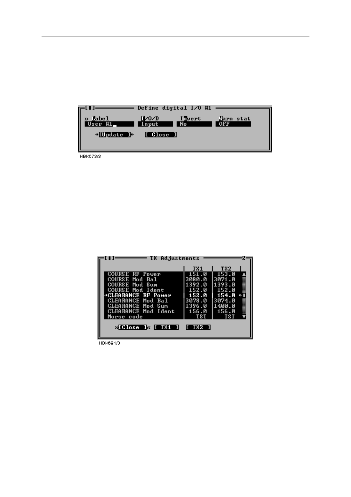
OPERATING MANUAL
INSTRUMENT LANDING SYSTEM
NORMARC 7013
The following definitions can be made for the digital user parameters: Name, input or output
selection, whether the value shall be inverted or not, and warning state of the parameter
(TRUE / FALSE / NONE).
To change the setting for a I/O parameter, select the parameter on the list and press the
“Change” button. This brings up the dialog shown below.
Figure 5-35 Digital user parameters settings dialog
For the counter parameters; the “Change” button opens a dialog where the label text can be
modified.
5.9 TX settings
5.9.1 TX Adjustments
Selecting the ILS|TX settings|TX adjustments menu item opens the window shown below.
Figure 5-36 TX adjustments window
The following TX parameter s can be changed for Course and Clear ance (2-freq. systems) for
transmitter 1 and 2:
• 90Hz & 150Hz modulation balance (DDM),
• 90Hz & 150Hz modulation sum (SDM),
• RF power
• Ident modulation depth
• In addition, the runway Morse code identification (2-4 letters) is entered here.
To change TX adjustment values click the TX1 or TX2 buttons. A dialog similar to the one
below will be opened. To change the parameter value you have the following options:
• Click on the up and down arrows to increment/decrement the value. The ILS will automati-
Remote Maintenance and Monitoring ©1999 Navia Aviation AS
5-28
21833-3.4
Page 67
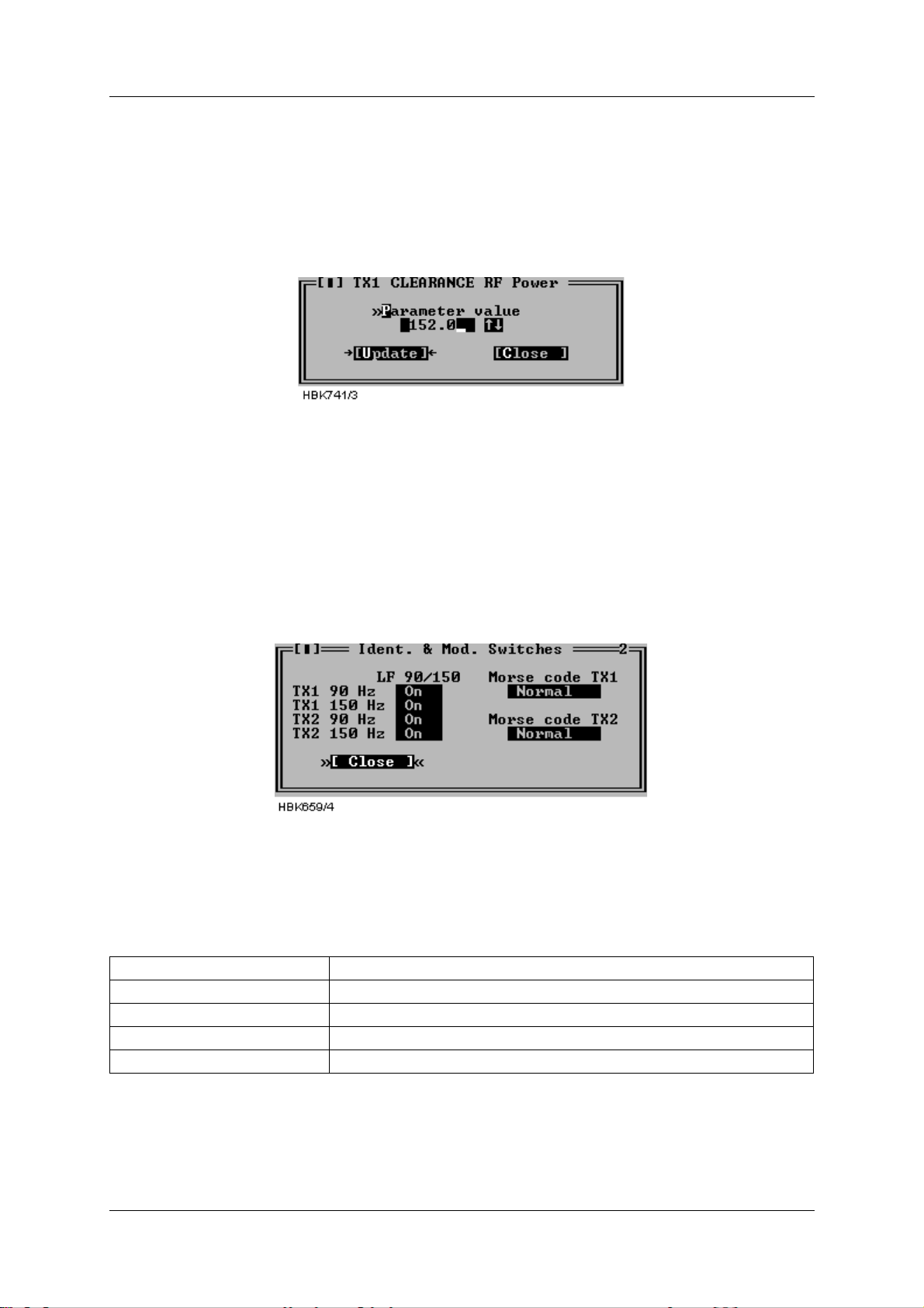
OPERATING MANUALNORMARC 7013
INSTRUMENT LANDING SYSTEM
cally be updated when you stop changing the value.
• Press the up and down arrows on your keyboard to increment/ decrement the value. Holding Shift down will increment/decrement by a larger value. The ILS will automatically be
updated when you stop changing the value.
• Enter a new value in the numeri c input f ield. The ILS will be updated when you p ress Enter
or click the Update button.
Figure 5-37 TX Adjustment input dialog
The TX-adjustment values are the positions of digital potentiometers used and stored in the
EEPROM on the LF generator boards. The values are unit-less integers in the range 0-4095.
See Appendix B for typical values used.
5.9.2 Ident. and modulation switches
Selecting ILS|TX settings|Ident. and modulation swit ches brings up the window shown below.
Figure 5-38 Ident. and modulation switches window
In this window the LF generator 90 Hz and 150 Hz signals may be switched on or off and the
Morse code and VOICE settings may be changed (LLZ only). VOICE on/ off is only applicable
for VOICE configured Localizers. The following t able descr ibes the ef fec t of each Morse code
setting.
Setting Transmitted ident.
OFF None (silent)
NORMAL The one selected in TX adjustments - Morse code
CONT. Continuous 1020 Hz tone.
TST The Morse code for TST
Table 5-10 Morse code settings.
5.9.3 CLR mod. and DME settings
Selecting ILS|TX settings|CLR mod. and DME settings brings up the window shown below.
©1999 Navia Aviation AS 21833-3.4 Remote Maintenance and Monitoring
5-29
Page 68
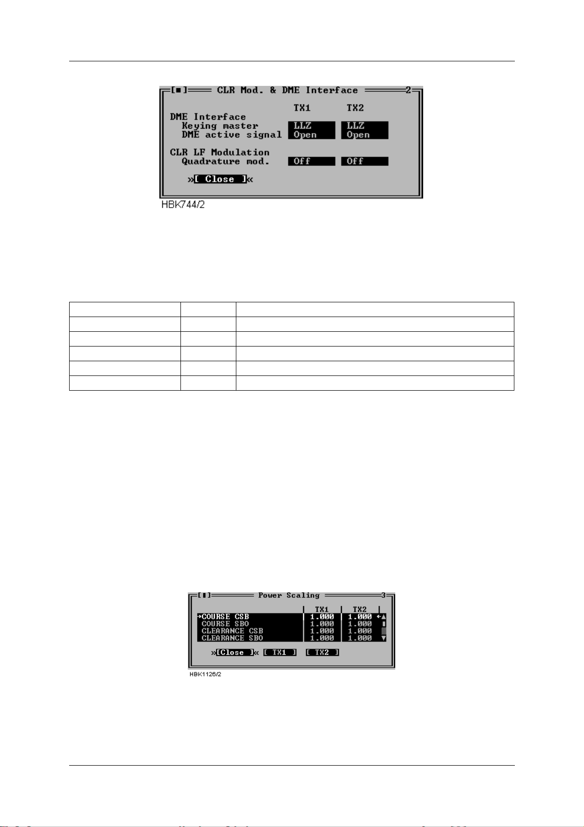
OPERATING MANUAL
INSTRUMENT LANDING SYSTEM
NORMARC 7013
Figure 5-39 CLR mod. and DME settings dialog
The fields in this window specifies the operati on of the DME interface (LLZ only) and quadrature modulation of the CLR LF signal (2-freq. systems only).
The following table describes the each selection.
Keying master LLZ LLZ is the keying master
DME DME is the keying master
DME active signal OPEN Open circuit indicates active DME (enables colocation)
CLOSED Closed circuit indicates active DME (enables colocation)
Quadrature mod. OFF Do not quadrature modulate the clearance LF signal.
ON Enable quadrature modulation of the clearance LF signal.
Table 5-11 CLR modulation and DME settings.
5.10 Power scaling
NOTE
The scaling values in this window should only be changed on racks with the first ver-
sion of the PA module (LPA1230A/GPA1231A/GPA1232A version 1). On newer PA mod-
ules, the power reading is pre-adjusted, and the scaling value shoul d be set to 1.0.
Selecting ILS|TX Settings|Power scaling when connected to an ILS with RMS software version 10, or later, will bring up the window below.
Figure 5-40 Power scaling settings
The scaling values will normally be in the range 0.5-2.0.
The values in this window can be used to adjust the power measurements done on the trans-
mitters. The measurement values are displayed in the maintenance windows for the transmit-
Remote Maintenance and Monitoring ©1999 Navia Aviation AS
5-30
21833-3.4
Page 69
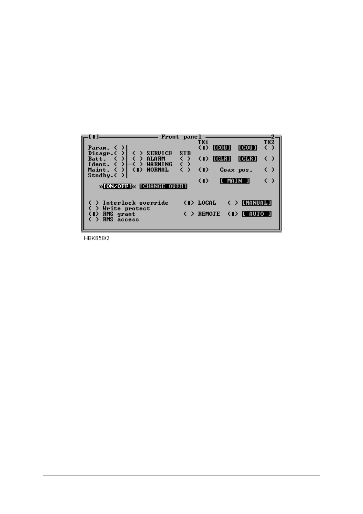
OPERATING MANUALNORMARC 7013
INSTRUMENT LANDING SYSTEM
ters.
These scaling values are stor ed in the RMS s ystem in t he ILS. Thi s implies that the values will
have to be changed if a PA module is replaced.
5.11 Front panel operation
When ILS|Front panel is selected a window displaying the same information as the ILS front
panel is opened. See Figure 5-41.
Figure 5-41 Front panel window
Pressing buttons in this window has the sa me effect as pressing the corresponding switch on
the ILS front panel.
Note that some switches on the ILS front panel is not possible to change from the RMM system (e.g. write protect). The settings of these switches is displayed as “LED’s” in this window .
5.12 Get historical data
5.12.1 General
Selecting ILS|Get historical dat a opens the Storage download window, shown in Figure 5-42.
This window is used to download one of the data storages.
The different storages contain the following information. All stored items are given a corresponding time stamp:
• Alarm storage: Samples of all monitor and maintenance parameters for a period starting
from 30s before an alarm occurred and ending with the actual alarm sample. Up to 7 alarm
storages can be stored in the ILS. The RMM will download all storages into one alarm storage file.
• Warning storage: One sample of al l monitor and maintenance parameters at the ins tant
when a warning LED is activated. The 25 last warnings are stored.
• Medium time periodic storage: One sample of all monitor and maintenance parameters
stored periodically at user specifi ed intervals (see 5.22). The storage contai ns the last 96
samples.
• Long time periodic storage: For every day through a 180 days period, the mean value and
©1999 Navia Aviation AS 21833-3.4 Remote Maintenance and Monitoring
5-31
Page 70
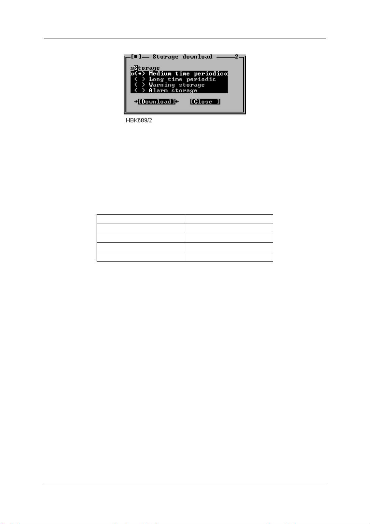
OPERATING MANUAL
INSTRUMENT LANDING SYSTEM
NORMARC 7013
standard deviation of all monitor and analog maintenance parameters.
Figure 5-42 Storage download window
E.g. to download the alarm storage buffer; just select the Alarm storage radio button and
press the “Download“ button. The software will then retrieve the alarm storage and store the
data on the local hard disk.
The software automatically creates a name for the fi le in which the data is st ored. The name is
of the form YYMMDD.ext. Where YY is the last two digits of the cur rent year, MM is the month
and DD is the day of month number. The fi lename extension field is defined in the following
table.
Storage type Extension
Medium time periodic .MED
Long time .LON
Warning .WRN
Alarm .ALA
Table 5-12 Filename extensions.
The file will be created in the directory specified in the Log dir. field of the current station
setup.
5.12.2 Alarm storage specific
The software will check the .ALA file for the current day (if it exists) to see wheth er or not a
new alarm has occurred. If no new alarm is available in the ILS storage buffer no data will be
downloaded, and you will be notified about the situation.
5.13 Continuous data logging
When ILS|Continuous logging is selecte d the dialog in Figure 5- 43 is opened. From this di alog
the user controls the writing of received data to a file. The data written to a file can be displayed on screen and exported to text format f or later use in a spreadsheet program. The user
may select which types of data to be stored on disk, as displayed in Figure 5-43.
Remote Maintenance and Monitoring ©1999 Navia Aviation AS
5-32
21833-3.4
Page 71
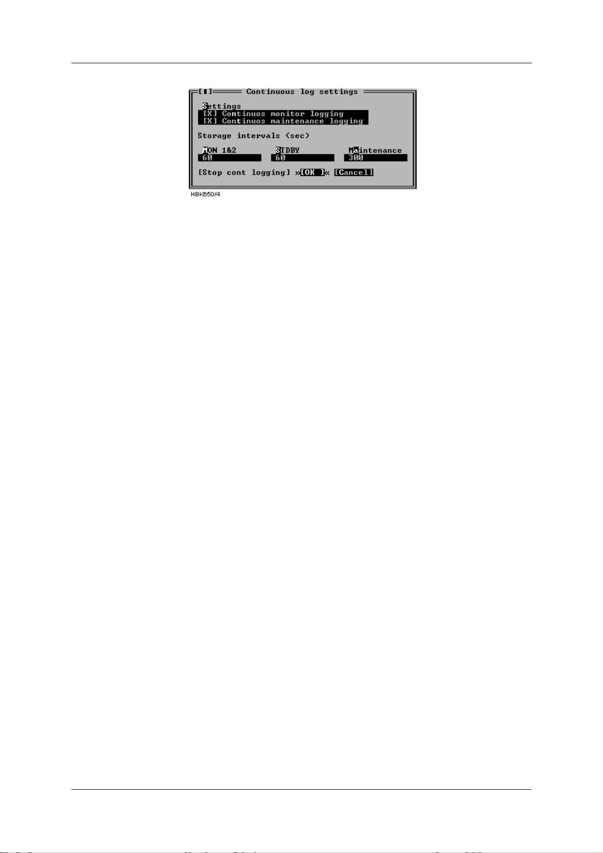
OPERATING MANUALNORMARC 7013
INSTRUMENT LANDING SYSTEM
Figure 5-43 Continuous logging dialog
The time interval between each time a sample is stored can also be configured in t his dialog.
The intervals must be entered in seconds and tenths of a second. The storage interval information entered in this dialog will be stored and associated with the current station.
The software automatically creates a name for the fi le in which the data is st ored. The name is
of the form YYMMDD.ext. Where YY is last two digit s of the current y ear , MM is the mont h and
DD is the day of month number. The filename extension field is CNT.
The file will be created in the directory specified in the Log dir. field of the current station
setup.
The "Stop cont logging" button in this window can be used to stop logging continuous data
(once it has been enabled). When continuous logging has been turned on the "Continuous
log" field in the Link window displays "ON".
5.14 Events
Selecting ILS|Events brings up the window shown in Figure 5-44. This window displays the
last 50 events (user operations , log -in/out, alarms, war nings) i n a scroll able li st. The di splayed
fields are:
• The time when the event occurred
• The user caused the event (if any)
• The event type description
Event diagnostics is also invoked from this window, see chapter 5.24 for a description of this
feature.
©1999 Navia Aviation AS 21833-3.4 Remote Maintenance and Monitoring
5-33
Page 72
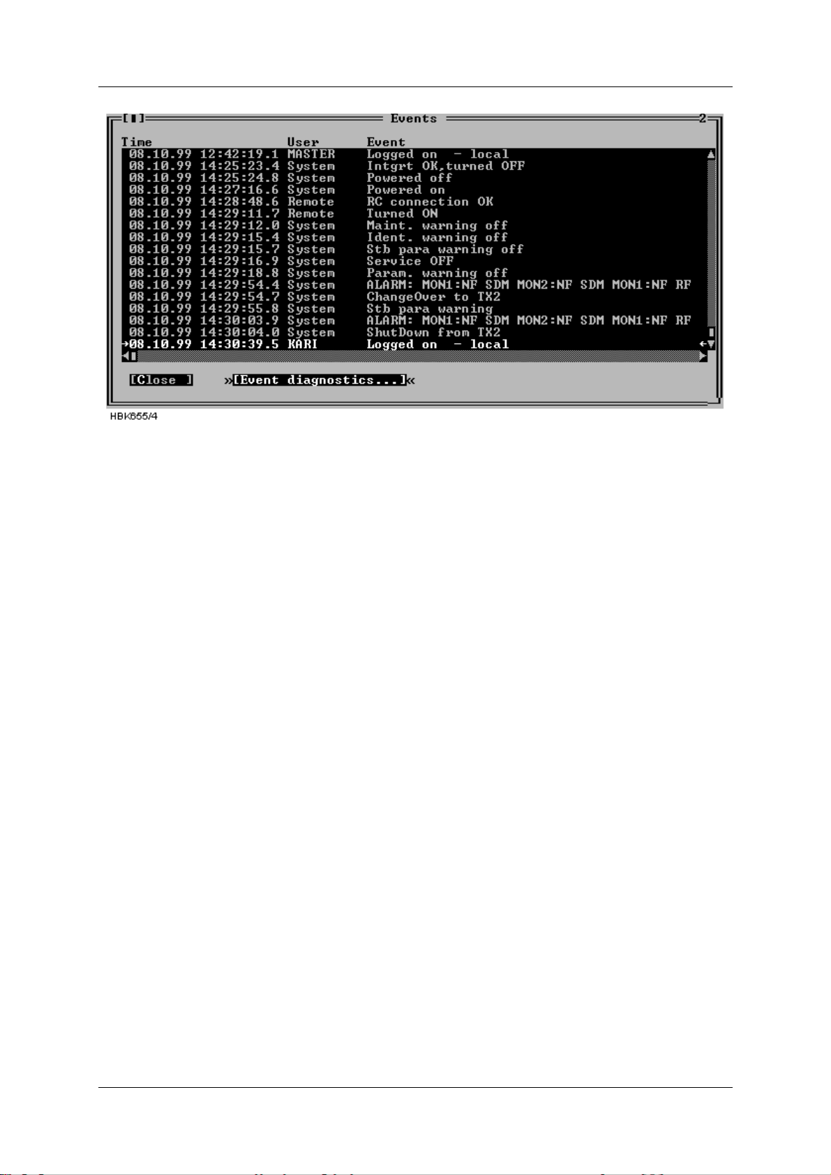
OPERATING MANUAL
NORMARC 7013
INSTRUMENT LANDING SYSTEM
Figure 5-44 Events window
5.15 Test DDM
The ILS|Test DDM function is for use when a DDM flight test is performed on the system. The
Test DDM window is shown in Figure 5-45. The window contains the following fields:
• The current CL and NF DDM nominal, measurement, and low and high alarm limit.
• Buttons for quick access to the monito r alarm/warning configuration dialog (see chapter
5.8.1).
• DDM adjustment “potentiometers” for adjusting dominance levels.
The Inc and Dec buttons increase/decrease the dominance level.
NOTE: Pressing Inc on a 150 Hz level will decreas e the potentiometer value, while Dec will
increase the value.
• Toggles for setting the type of dominance (toggles between Off, 90 Hz and 150 Hz)
The required access levels for the fields in this dialog is as follows:
• To change monitor limits (use of the “monitor CL/NF DDM” buttons) requires access
level 3.
• All other settings require access level 2.
Remote Maintenance and Monitoring ©1999 Navia Aviation AS
5-34
21833-3.4
Page 73
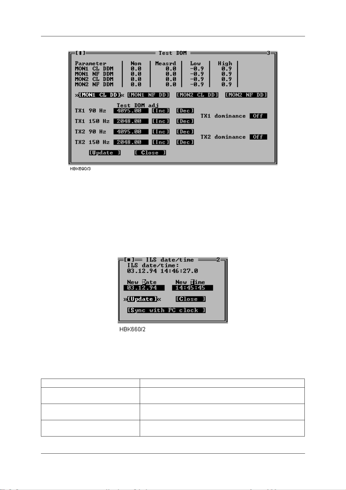
INSTRUMENT LANDING SYSTEM
OPERATING MANUALNORMARC 7013
Figure 5-45 Test DDM window
The test DDM values are unit-less integers in the range 0-4095.
5.16 Set ILS date/time
The functionality of the ILS|Set ILS date/time window depends on whether or not the user is
logged in as an ordinary user or as master user. When logged in as a master user this window
allows setting of the ILS RMS system clock. When logged in as an ordinary user, this window
displays the current ILS RMS system date/time.
Figure 5-46 ILS date/time window.
The available master user operations is outlined in the table below.
Field Description
New Date Holds the date to be sent to the ILS upon an Update but-
ton activation.
New Time Holds the time to be sent to the ILS upon an Update but-
ton activation.
Update (button) Sets the ILS RMS clock to the date/time specified in the
New Date and New Time fields.
©1999 Navia Aviation AS 21833-3.4 Remote Maintenance and Monitoring
5-35
Page 74
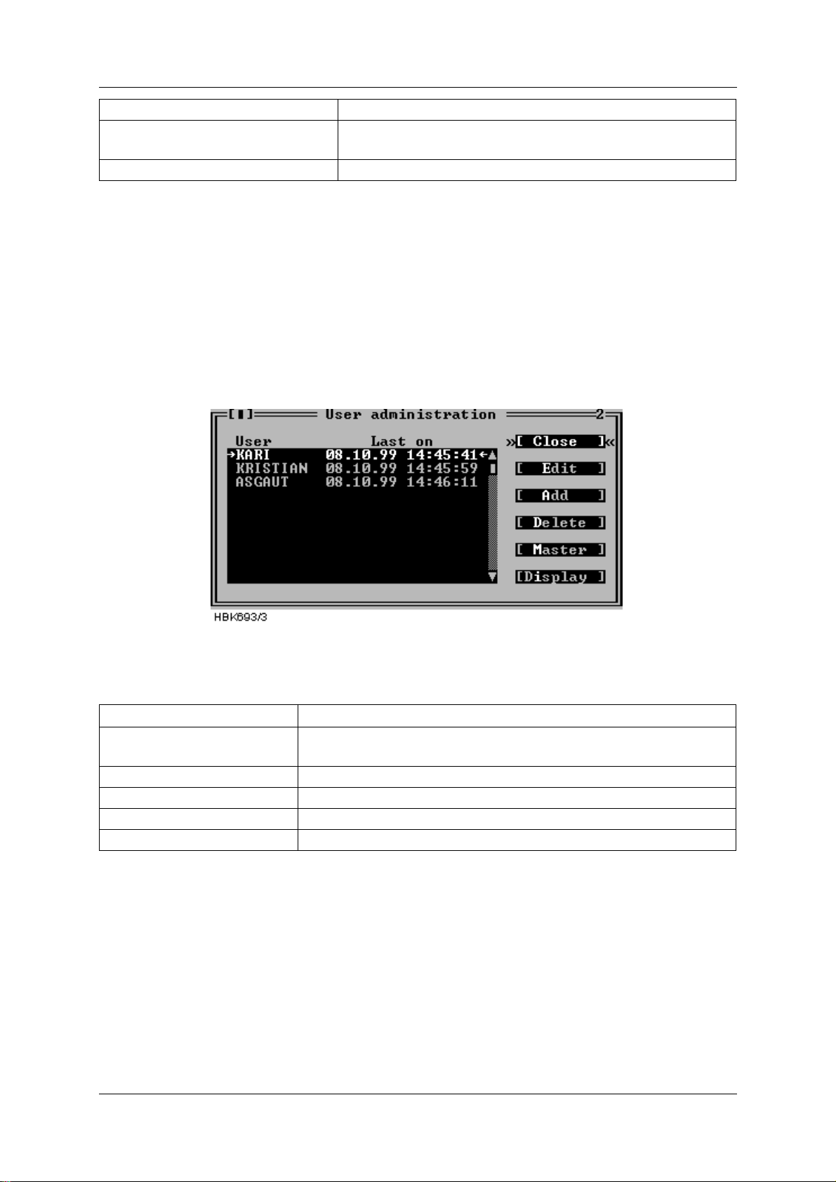
OPERATING MANUAL
INSTRUMENT LANDING SYSTEM
NORMARC 7013
Field Description
Sync with PC clock (button) Sets the ILS RMS clock equal to the local PC system
clock.
Close (button) Closes the ILS date/time window.
Table 5-13 Master user available operations.
5.17 User administration
The functionality of the ILS|User list/adm. window depends on whether or not the user is
logged in as an ordinary user or as master user. When logged in as a master user this window
allows configuring of existing and new users which shall be granted access to the RMM system. When logged in as an ordinary user, this window only displays the last time each user
was logged on.
The following is a description of the available operations when logged in as a master user.
Figure 5-47 User administration window
The available master user operations is outlined in the table below.
Operation
(button)
Description
EDIT Edit the username and/or passwords for the currently selected
user
ADD Add a new user
DELETE Delete the currently selected user
MASTER Edit the passwords for the master user
DISPLAY Edit the password for the ILS front panel display pa nel.
Table 5-14 Master user operations.
When Edit, Add or Master is selected in the User administration window a dialog showing the
currently defined username and p asswords i s opened. In t his dia log y ou may enter or c hange
the username and password(s).
Note that passwords must be 6-8 characters in length. Both the username and passwords
should only consist of characters in the range A-Z, a-z or 0-9.
The username for the master user cannot be changed.
Remote Maintenance and Monitoring ©1999 Navia Aviation AS
5-36
21833-3.4
Page 75
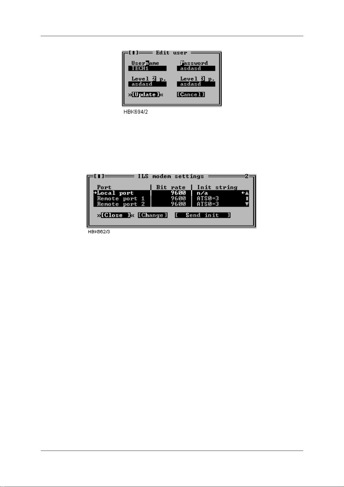
OPERATING MANUALNORMARC 7013
INSTRUMENT LANDING SYSTEM
Figure 5-48 User configuration dialog
5.18 ILS Modem settings
With access level 3 you have access to change ILS modem bit rate and initiat ion strings and
make the ILS initiate the modems. Selecting ILS|Modem configuration brings up the window
shown below.
Figure 5-49 ILS Modem settings window.
The window displays the currently configured bit rates and init strings. Pressing the Change
button brings up a dialog where you can change the bit rate and/or the init string for the
selected port. Note that i t is no i nit stri ng f or t he local por t, s ince a modem is not su pported f or
this port.
Pressing the Send init button st arts modem initiation at the sel e cted port. When the ILS is
done initiating a dialog showing the result of the modem initiation will appear.
If the init-string is l eft blank or t he word «default» i s written, th e ILS will use a defaul t init-string
that shall work on standard Hayes compat ible modems under normal conditions.
Please consult the modem manual for further in formation about modem commands and initialisation.
5.19 Upload configuration to ILS
Several boards in the NORMARC 7000 cabinet store settings or operationa l parameters in
internal EEPROM. Whenever a new board is inserted in a cabinet, these parameters need to
configured. This can be done by “uploading” the parameter values to the cabinet with the use
of the “ILS | Configuration options | Upload configuration to ILS” menu item. When this menu
item is chosen, a window for selecting a previously stored “CFG” file (see section 5.20) is displayed.
Once the user has selected the file containing the de sired configuration parameters, the window shown in Figure 5-50 is opened. This window lists boards for which the configuration may
©1999 Navia Aviation AS 21833-3.4 Remote Maintenance and Monitoring
5-37
Page 76
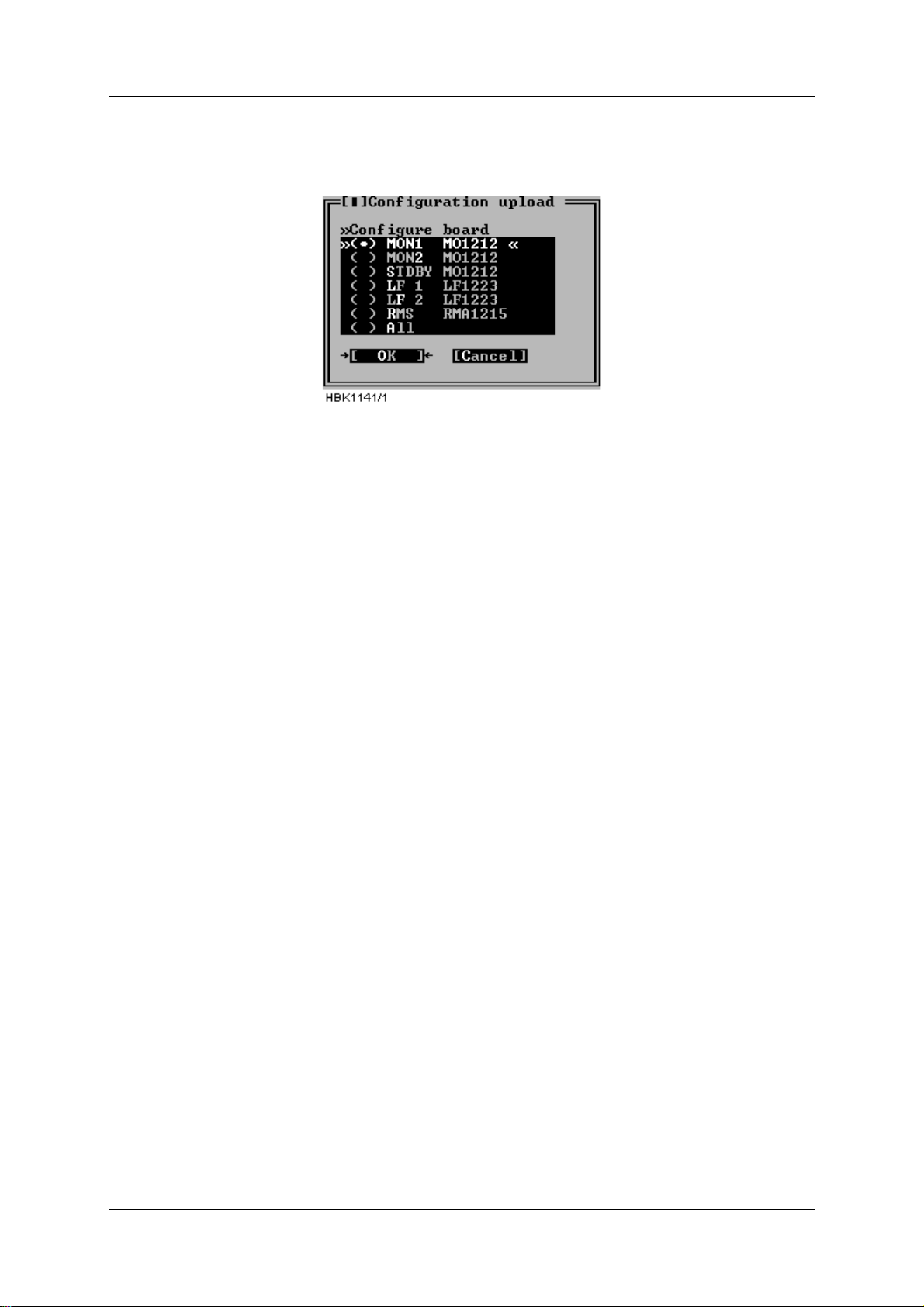
OPERATING MANUAL
INSTRUMENT LANDING SYSTEM
NORMARC 7013
be uploaded. Configuration for one board or all boards (normally used only for new cabinets)
can be uploaded.
This is an access level 3 operation.
Figure 5-50 Configuration upload
When the OK button is clicked, the RMM software starts the upload and displays a window
telling the user that the operati on is in progress. The upload may take a few minutes, depending on the board type selected for upl oad. In order to sp eed up the upload proc ess, it is a good
idea to close all windows that display monitor or maintenance measurements (this frees up
communication bandwidth).
Note 1: Refer to chapter 7 for detailed info rmation on uploading configuration after e.g. a
board replacement.
Note 2: The following configuration data for the RMS board are not stored in the c onfigur ation
file and therefore require manual updating: “Lamp mappings ”, “ILS modem configu ration”, and
“User list/ adm.”.
5.20 Write configuration to file
As described in section 5.19, different boards store configuratio n data in internal EEPROM.
The configuration data can be stored on disk with the use of the “ILS | Configuration options |
Write configuration to file” menu item. Sel ecting this menu it em brings up the window shown in
Figure 5-51 The user must enter a new filename, or select an existin g file for storing the configuration parameter s. If an existing file is selected, the user is asked whether or not the file
should be overwritten.
Remote Maintenance and Monitoring ©1999 Navia Aviation AS
5-38
21833-3.4
Page 77
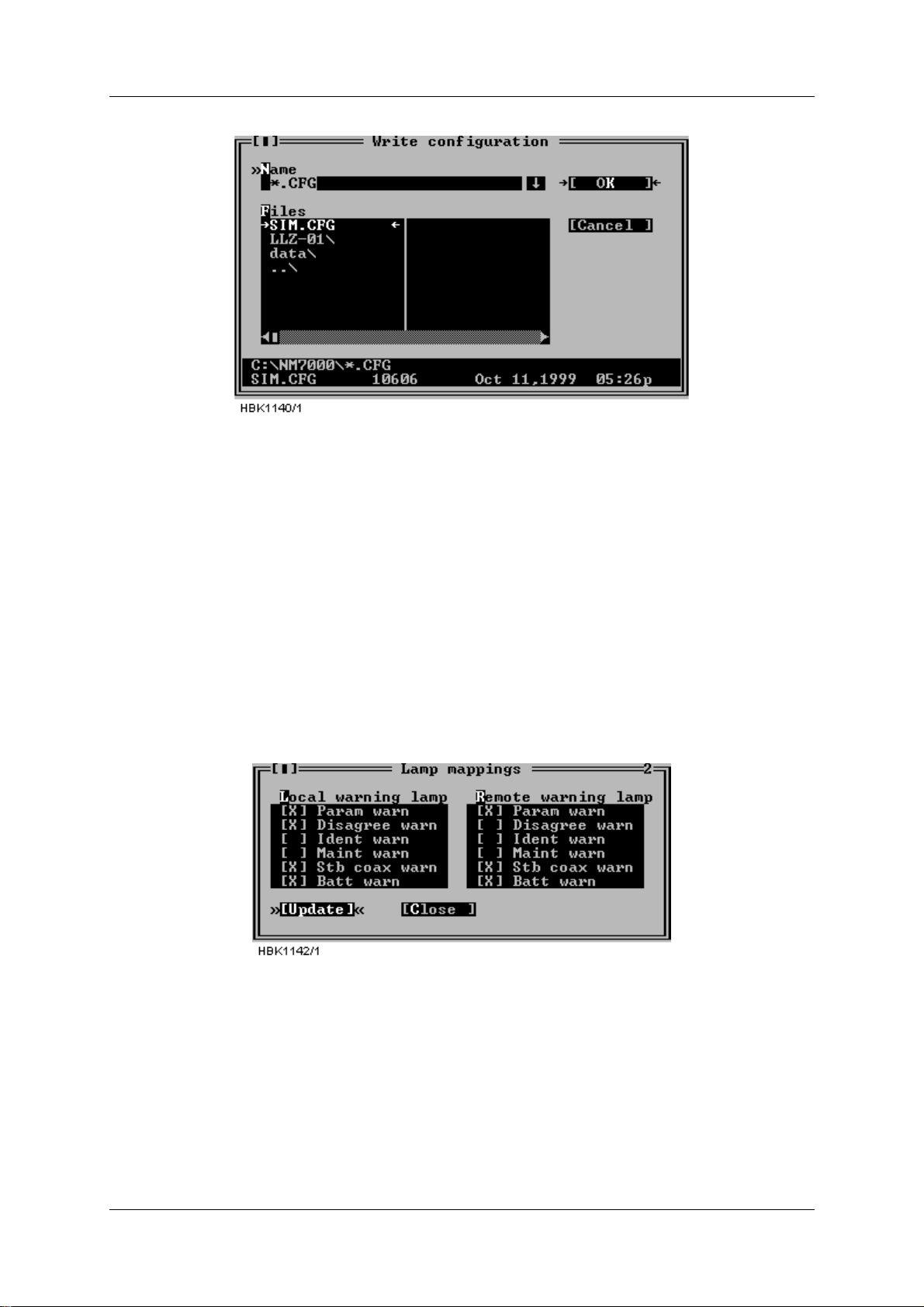
OPERATING MANUALNORMARC 7013
INSTRUMENT LANDING SYSTEM
This is an access level 1 operation.
Figure 5-51 Write configuration to file.
The configuration file is a plain ASCII text file. The file may be inspected by the user, but to
avoid introducing possible errors, it is not recommended to manually edit it
5.21 Lamp mappings
At access level 3 the user may configure which of the small warning LED’s that are “mapped”
to the main (big) warning LED on the local an remote control panels.
Figure 5-52 shows the window that appears when the “ILS | Configuration options | Lamp
mappings” menu item is selected. An “X”-mar k to the lef t of the war ning type indi cates th at an
active warning of that type will cause the corresponding main warning lamp to be activated.
If the configuration is changed, remember to click the “Update” button to send the new settings to the cabinet.
Figure 5-52 Lamp mappings HBK1142
5.22 Medium storage sample interval
The sample intervals for the medium time storage may be selected by choosing ILS| Configuration options| Medium storage sample interval. This brings up the window shown below.
©1999 Navia Aviation AS 21833-3.4 Remote Maintenance and Monitoring
5-39
Page 78
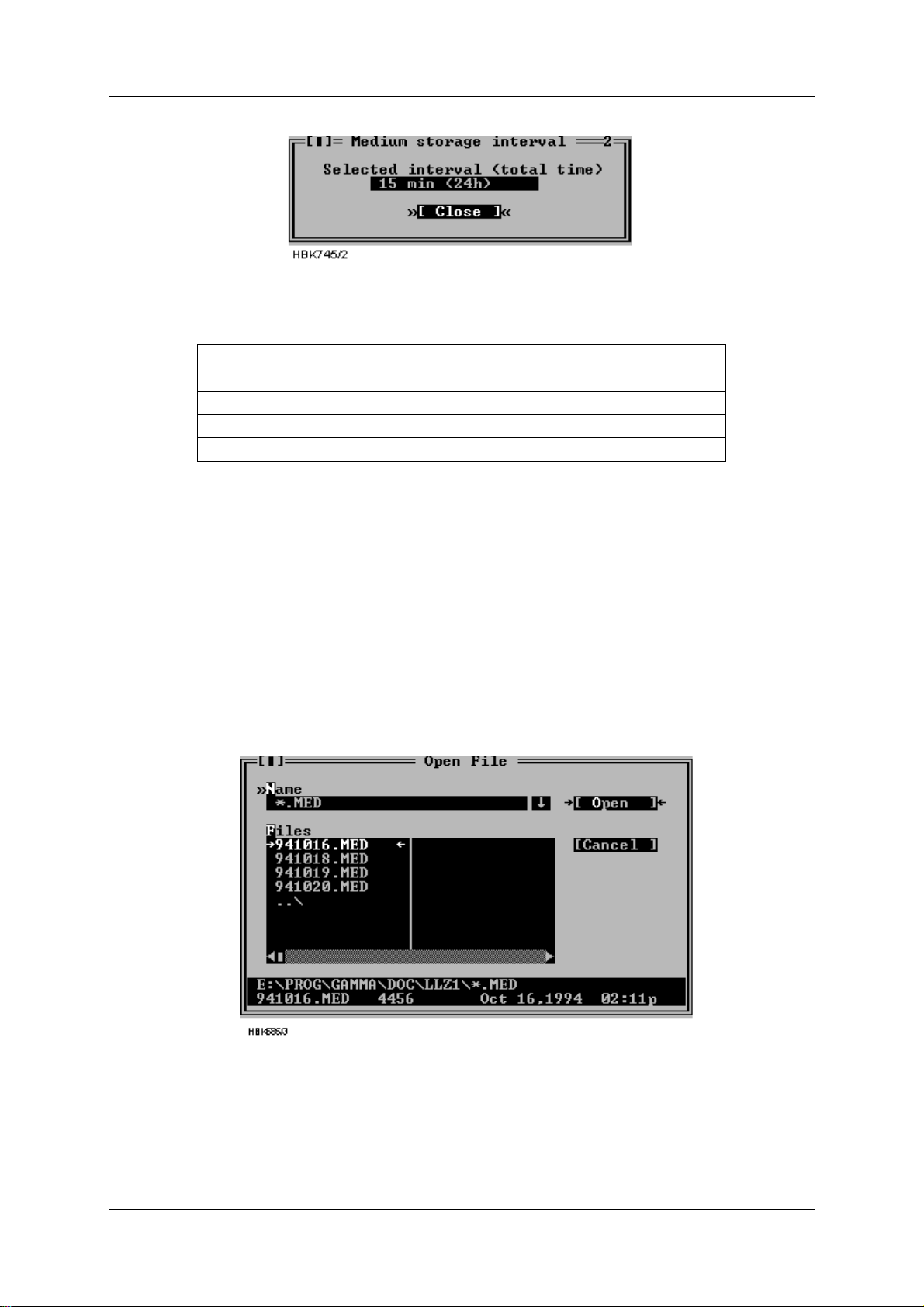
OPERATING MANUAL
Figure 5-53 Medium storage interval setting dialog
The following intervals way be selected
Storage interval Total medium storage time
15 Minutes 24 Hours
30 Minutes 48 Hours
60 Minutes 4 Days
120 Minutes 8 Days
Table 5-15 Medium time storage interval settings
NORMARC 7013
INSTRUMENT LANDING SYSTEM
5.23 Disp laying stored measurements
5.23.1 General
This chapter describes how t o open and di splay a st orage buf fer after i t has been downl oaded
and stored on the local hard disk, as described in chapter 5.12.
The desired file is opened by selecting File|Open log. A dialog l ike the one shown below will
be displayed. This dialog shows the files matching the wild card mask in the Name field. The
directory may be changed by double clicking (or by pressing Enter) a list entry with a back
slash (“\”) appended to the name.
Figure 5-54 Open log file dialog
When a selection has been made a new window will be opened. This window displays information about the data stored in the opened file. The different types of storage files have different information displayed in this window, as described in the following chapters.
When a this window is opened, you would display the stored status/measurements by open-
Remote Maintenance and Monitoring ©1999 Navia Aviation AS
5-40
21833-3.4
Page 79
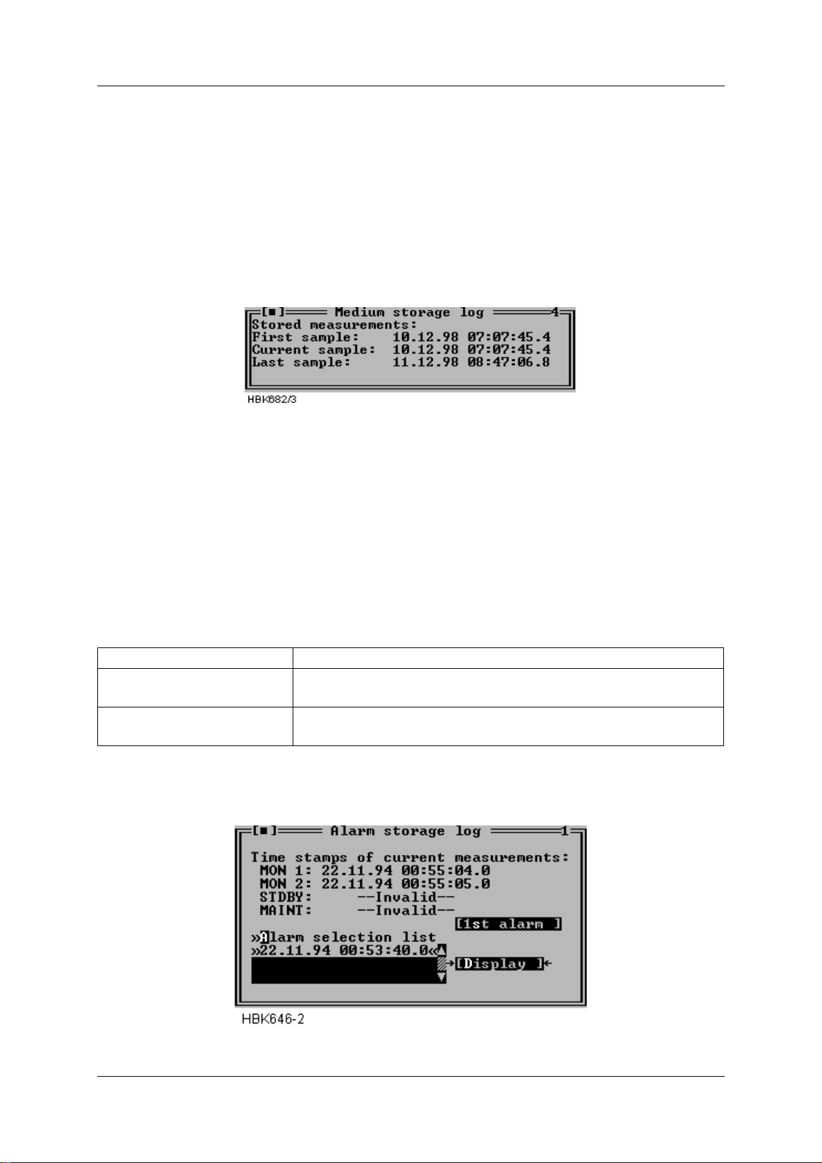
OPERATING MANUALNORMARC 7013
INSTRUMENT LANDING SYSTEM
ing the appropriate windows by selecting menu items from the ILS menu. Note t hat some
menu items will not be accessible because some information types is not stored in the log file.
To move back and forth in the stored data, press F7 and F8.
5.23.2 Medium time periodic (MED)
When a MED file has been opened a window as shown below will be opened.
This window displays the time stamps of the first, the currently displayed one, and the last
sample stored in the file.
Figure 5-55 MED file log window
5.23.3 Alarm storage (ALA)
When an ALA file has been opened a window as shown below will be opened. This window
shows the time stamps of the currently displayed Monitor 1, Monitor 2, Standby (if installed)
and Maintenance monitor samples. This window also has a list where you select an alarm to
study.
The operation of the window is outlined in the table below.
To accomplish this Do this
Study a specific alarm Select the desired alarm on the alarm selection list and press
the “Display” button.
Advance to the first raw
Press the “1st alarm” button.
alarm state
Table 5-16 Alarm storage operations.
Figure 5-56 ALA file log window
©1999 Navia Aviation AS 21833-3.4 Remote Maintenance and Monitoring
5-41
Page 80
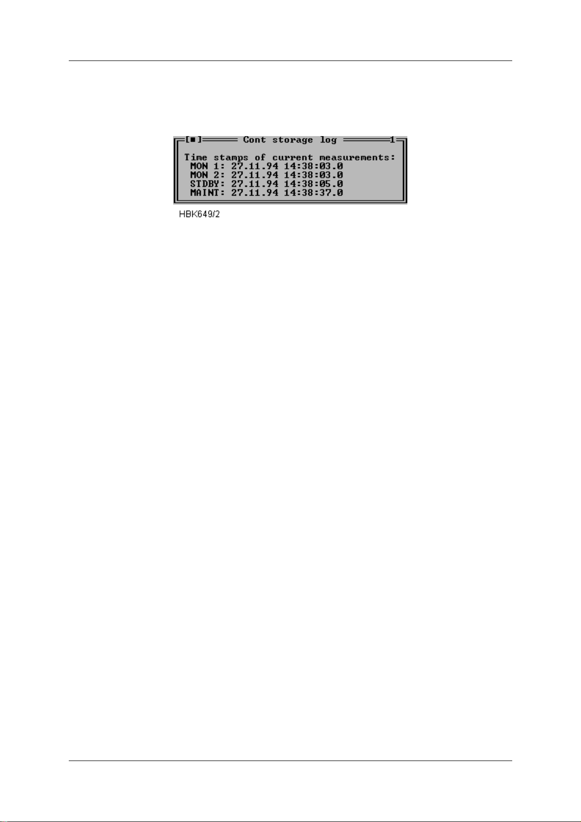
OPERATING MANUAL
INSTRUMENT LANDING SYSTEM
NORMARC 7013
5.23.4 Continuous data log (CNT)
When a CNT file has been opened a window as shown below will be opened. This window
shows the same information as the Alarm storage window, except that this window does not
have the alarm specific functions.
Figure 5-57 CNT file log window.
5.24 DIAGNOSTICS
5.24.1 General description of the diagnostic functions
The NM7000 RMM system has two algorithms to isolate a failure in the ILS. The algorithms
are the Current data diagnostics and the Alarm Event diagnostics. See chapter 7 for a thor-
ough description of these alghorithms.
5.24.2 Current data diagnostics
This diagnostic function are invoked by selecting ILS|Current data diagnost ics. Based upon
the current status of the equipment, the program will suggest the faulty module, if any.
5.24.3 Alarm Event diagnostics
This diagnostic function are invoked from the Event l ist window. A CHANGEOVER or SHUTDOWN event must be selected in the event list, then may the diagnostic function be invoked
by pressing the Event diagnostics button below the event list. Based upon the nature of the
CHANGEOVER or SHUTDOWN event, combined with the contents of the corresponding
alarm storage, the program will suggest the faulty module which originated the alarm. Note
that the event storage diagnostics function will only be able to isolate faults to module level
when a single fault has occurred
5.25 Exporting data
You can export stored measurements to a spreadsheet with the function described in thi s section. Exported data will be stored in an ASCII tex t file. This text file may then be imported into
a spreadsheet program or a graphical present ation program.
Data from all types of log files may be exported.
The Export data function i s located on the fil e menu. In order to use the function, y ou must first
open the log file from which you want to export data. This is done by using the File|Open log
function (described in chapter 5.22) . When a log file has been opened you may select the
Export data function. The dialog shown in Figur e 5-58 wil l appear. Select the type of data to
export and press OK. You will be prompted to enter a file name for the exported data. The
Decimal point field selects the type decimal point character used when stored data are
exported to a text file. Select the p roper setting for use by your spreadsh eet progra m or graphical presentation pro gram.
Remote Maintenance and Monitoring ©1999 Navia Aviation AS
5-42
21833-3.4
Page 81
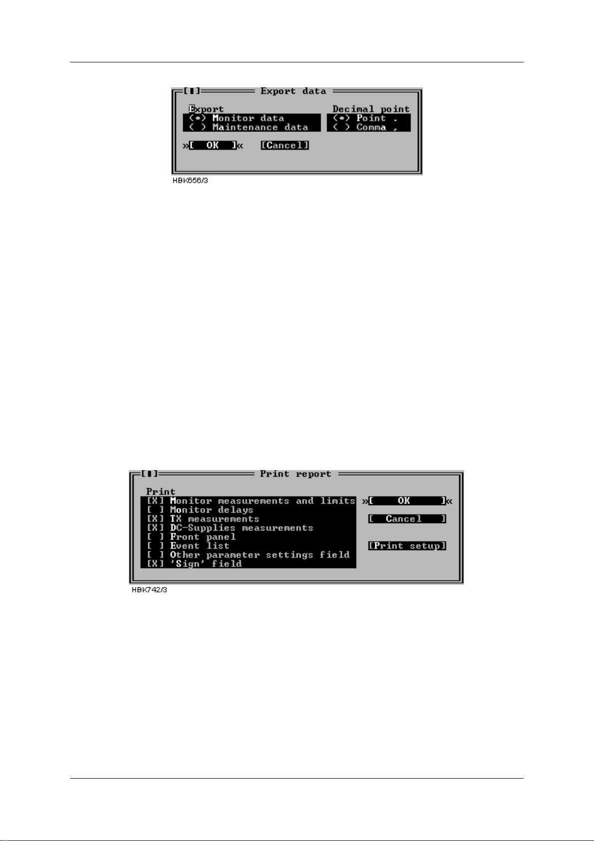
OPERATING MANUALNORMARC 7013
INSTRUMENT LANDING SYSTEM
Figure 5-58 Export data dialog
Each field in the export file are separated by a TAB character. Each line contains all measurements in a sample. The line begins with the time stamp of sample (resolution 1 second). The
next field is 1/10 seconds of t he time st amp. The r est of the l ine is the measur ement s/ p arameters of the sample.
The type of decimal point used for analog measurements is defined by Decimal point setting
in the Preferences dialog (see chapter 5.4.4).
Digital parameters (OK/ ERROR) are export ed as numbers, 0 and 1. 1 equals OK, and 0 indicates ERROR.
5.26 Printing reports
When you are logged in on an ILS you can make printouts of several measuremen ts and configurations.
The Print Report function is located on the file menu. To use it you must first connect and log
in on a ILS rack (access level 1). Figure 5-59 shows the Print Report dialog which is opened
when you select the File|Print report menu item.
Figure 5-59 Print Report dialog
The system will print the data you select in the ‘P rint’ section of the dialog. The Print setup
button is a shortcut to the Options|Print setup di alog, described in chapter 5.4.3.
5.27 Print screen
To print the screen contents in the Windows 95/NT version, select the File|Print screen menu
option. This will send the cur rent sc reen cont ent s t o t he pri nter por t select ed in t he Pri nt setu p
window.
To print the screen under DOS use the "Print Screen" key on the PC keyboard. This will print
the screen on LPT1 (independent of the port selected in the Print setup window).
©1999 Navia Aviation AS 21833-3.4 Remote Maintenance and Monitoring
5-43
Page 82
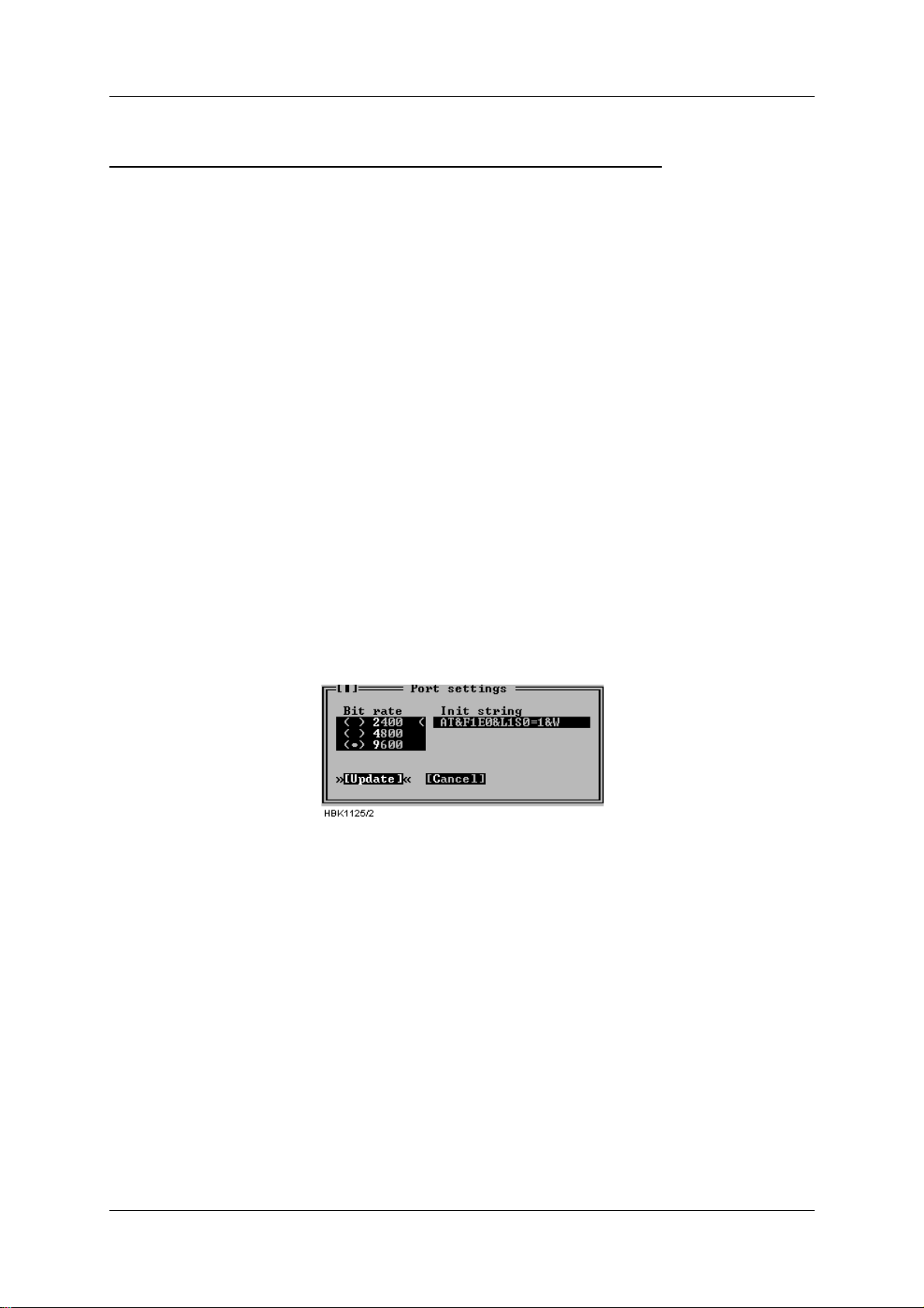
OPERATING MANUAL
INSTRUMENT LANDING SYSTEM
NORMARC 7013
5.28 Technical note - Leased line SETUP (USRobotics)
USING NM7000 RMM SOFTWARE WITH LEASED LINE CONNECTION
Applies to USRobotics Courier Dual Standard V.34+ modems
5.28.1 Definitions
Local modem The modem attached to the PC running
NM7000 RMM software.
Remote modem The modem attached to the NM7000
cabinet.
5.28.2 Configuring the remote modem
1. Set DIP switches on the remote modem.
• Switch 1 must be set to the DTR ALWAYS ON position.
• Switch 4 must be set to the ON position - Do not echo offline commands
• Switch 5 must be set to the AUTO ANSWER ON RING position.
• The remaining switches should be left in their factory default positions.
2. Connecting the modem to the cabinet.
• The remote modem must be connected to Remote Port 2 on the connection interface
board in the ILS cabinet.
3. Configure remote modem init string.
• With a PC running NM7000 RMM software, log in with MASTER access on the Local Port.
• Select «Modem configuration» from the ILS menu.
• Set the Remote port 2 modem configuration as follows (all ‘0’ letters are zeroes):
Figure 5-60 ILS port settings for leased-l ine connections
4. Initializing the remote modem.
• Pressing the «Send init» butt on in the ILS modem se ttings windo w makes the ILS send the
initialization string on the port selected in the port list.
• The ILS will also send the these init strings when the I LS is powered on.
5.28.3 Configuring the local modem
1. All modem DIP switches should be left in their factory default positions.
Remote Maintenance and Monitoring ©1999 Navia Aviation AS
5-44
21833-3.4
Page 83
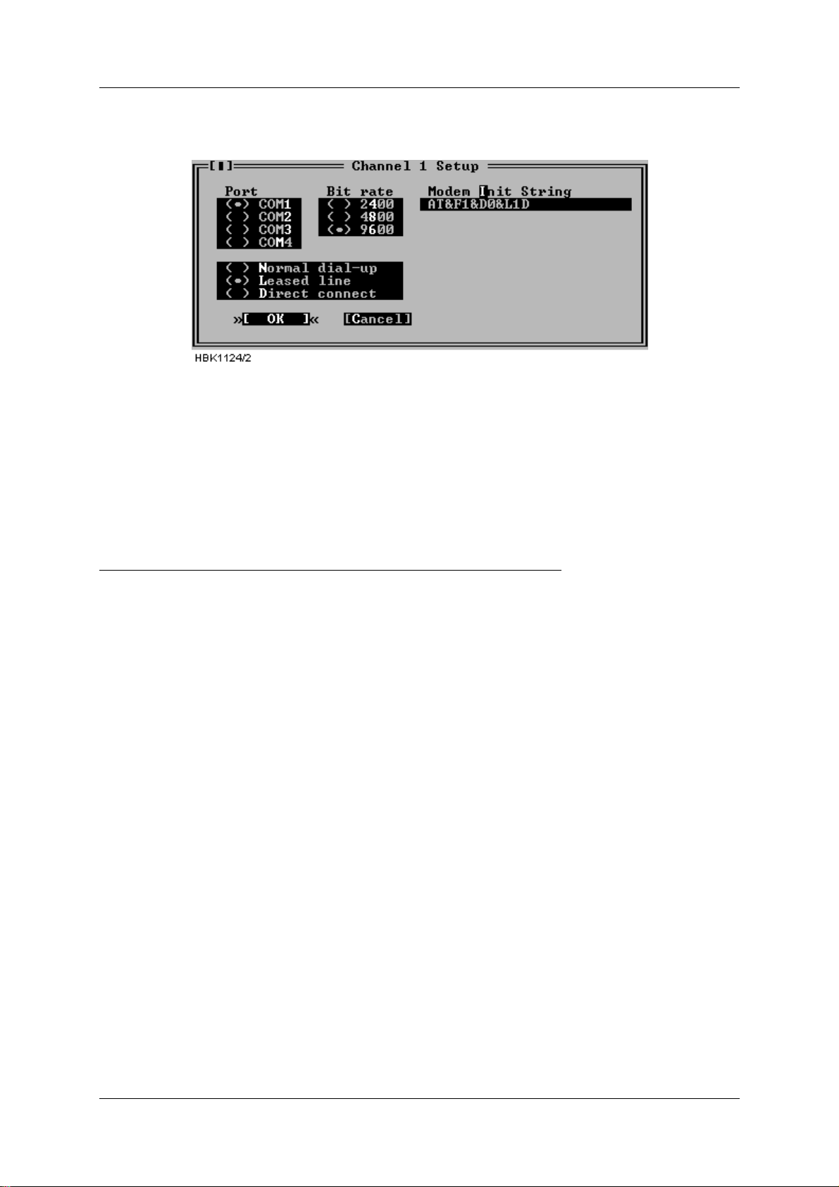
OPERATING MANUALNORMARC 7013
INSTRUMENT LANDING SYSTEM
2. Configure the «Channel Setup» for the leased line connection as follows (all ‘0’ letters are
zeroes):
Figure 5-61 RMM channel setup for USR leased-line connections
The modem will be automatically set up for leased when a connection with this channel is
selected by the user.
Users of the DOS version should also select «Use DTR to hangup». The hangup string is
ignored.
5.29 Technical note - Dial up connection SETUP (USRobotics)
USING NM7000 RMM SOFTWARE WITH DIAL UP CONNECTION
Applies to USRobotics Courier Dual Standard V.34+ modems
5.29.1 Definitions
Local modem The modem attached to the PC running
NM7000 RMM software.
Remote modem The modem attached to the NM7000
cabinet.
5.29.2 Configuring the remote modem
1. Set DIP switches on the remote modem.
• Switch 1 must be set to the DTR ALWAYS ON position.
• Switch 4 must be set to the ON position - Do not echo offline commands
• Switch 5 must be set to the AUTO ANSWER ON RING position.
• The remaining switches should be left in their factory default positions.
2. Connecting the modem to the cabinet.
• The remote modem must be connected to Remote Port 2 on the connection interface
board in the ILS cabinet.
3. Configure remote modem init string.
• With a PC running NM7000 RMM software, log in with MASTER access on the Local Port.
• Select «Modem configuration» from the ILS menu.
• Set the Remote port 2 modem configuration as foll ows (All ‘0’ letters are zeroes.):
©1999 Navia Aviation AS 21833-3.4 Remote Maintenance and Monitoring
5-45
Page 84
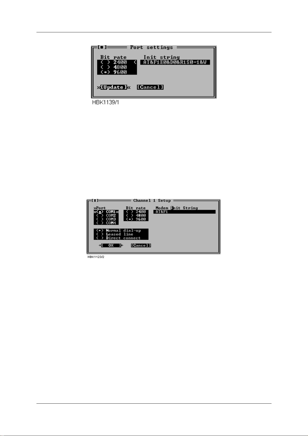
OPERATING MANUAL
INSTRUMENT LANDING SYSTEM
NORMARC 7013
Figure 5-62 ILS port settings for USRobotics dial up connection
4. Initializing the remote modem.
• Pressing the «Send init» butt on in the ILS modem se ttings windo w makes the ILS send the
initialization string on the port selected in the port list.
• The ILS will also send the these init strings each time the ILS is powered on.
5.29.3 Configuring the local modem
1. All modem DIP switches should be left in their factory default positions.
2. Configure the «Channel Setup» for the dial up connection as follows:
Figure 5-63 Local modem configuration
The modem will automatically dial and connect to the remote ILS whe n a connection with this
channel is selected by the user.
Of course, the teleph one number to dial wh en con necting to this st at ion must be conf igu red in
the ILS Station Setup window.
Users of the DOS version should also select «Use DTR to hangup». The hangup string is
ignored.
NOTE
Some PBX dial tones are not recognized by the modem. In this case the modem will not
start dialing when the user has selected a station to connect to. The problem is cor-
rected by entering X3 in the init string field. E.g.: AT&F1X3
Remote Maintenance and Monitoring ©1999 Navia Aviation AS
5-46
21833-3.4
Page 85

OPERATING MANUALNORMARC 7013
INSTRUMENT LANDING SYSTEM
5.30 Technical note - Leased line SETUP (WESTERMO)
This description applies to Westermo TD-32AC / TD-32DC modems.
5.30.1 DIP switch settings.
SW1: 1234
ILS Modem 0 1 0 1 Leased line, switch off echo and result code. All AT
commands ignored, including +++
PC-Modem 1 000Dial mode, configured from PC-program
SW2: 12345678
ILS Modem 1 0010000Enable SW2:2 to 7. Asynchro-
nous. DTR/DSR disconnected.
PC-Modem 1 0000000Enable SW2:2 to 7. Asynchro-
nous. DTR/DSR not disconnected.
SW3: 12345678
ILS and PC 1 00000002-wire connection.
SW4: 12345678
ILS and PC 0 11011009600 bps. 8 data bits. No stop
bits.
SW5: 12345678
ILS-Modem 1 1110000V.32bis, 9600 bps
PC-Modem 1 1110000Auto detect line parameters.
5.30.2 Connecting the modem to the cabinet.
The modem must be connected to Remote Port 1
1
or Remote Port 2 on the connection interface board in the ILS cabinet. The baud rate for this port mu st be 9600 bps (this is the default
setting). There is no need to configure any modem init strings in the NM7000 RMS.
5.30.3 Connecting the modem to the PC
The modem must be connected to COM1, 2, 3 or 4. The PC RMM modem connection type
should be set to Leased line. The modem init string should be:
AT\N5&D0&C1&L1&WD
(The hangup string is ignored in the DOS version)
1. It is recommended to use Remote Port 2 on the ILS, because this port has a 16 byte FIFO
that reduces the CPU load caused by the serial communication handlin g. If the modem must
be connected to Remote Port 1, a cable with R TS (pin 4) con nected to DSR (pin 6) both i n the
modem-end, must be used. Also, RTS must not be connected in the ILS-end.
©1999 Navia Aviation AS 21833-3.4 Remote Maintenance and Monitoring
5-47
Page 86

OPERATING MANUAL
INSTRUMENT LANDING SYSTEM
NORMARC 7013
5.31 Technical note - dial up SETUP (WESTERMO)
This description applies to Westermo TD-32AC / TD-32DC modems.
5.31.1 DIP switch settings.
SW1: 1234
ILS Modem 0 000Dial-up connection. Enable AT commands. Auto
answer.
PC-Modem 1 000Dial-up connection. Enable AT commands.
SW2: 12345678
ILS Modem 1 0010000Enable SW2:2 to 7. Asynchro-
nous. DTR/DSR disconnected.
PC-Modem 1 0000000Enable SW2:2 to 7. Asynchro-
nous. DTR/DSR not disconnected.
SW3: 12345678
ILS and PC 1 00000002-wire connection.
SW4: 12345678
ILS and PC 0 11011009600 bps. 8 data bits. No stop
bits.
SW5: 12345678
ILS and PC 1 1110000
Auto detect line parameters.
5.31.2 Connecting the modem to the cabinet.
The modem must be connected to Remote Port 1
1
or Remote Port 2 on the connection interface board in the ILS cabinet. The baud rate for this port must be 9600 bps. The init string for
the port should be:
ATE0&C1&D2&W
5.31.3 Connecting the modem to the PC
The modem must be connected to COM1, 2, 3 or 4 . The connect ion type i n the NM70 00 RMM
software must be set to Normal dial-up, the baud rate to 9600 bp s and the init string should
be:
ATX3&C1&D2\N5&W
In the DOS version, the Use DTR to hangup check box should also be checked (the hang-up
string will then be ignored).
1.It is recommended to use Remote Port 2 on the ILS, because this port has a 16 byte FIFO
that reduces the CPU load caused by the serial communication handlin g. If the modem must
be connected to Remote Port 1, a cable with R TS (pin 4) con nected to DSR (pin 6) both i n the
modem-end, must be used. Also, RTS must not be connected in the ILS-end.
Remote Maintenance and Monitoring ©1999 Navia Aviation AS
5-48
21833-3.4
Page 87

OPERATING MANUALNORMARC 7013
INSTRUMENT LANDING SYSTEM
PART III MAINTENANCE
6 Periodic maintenance CAT I and II
IMPORTANT:
No adjustments / alignments shall be done during a Periodic Maintenance. The
parameters should be recorded and compared with their nominal values only.
Over some time, the parameters may change due to natural variations. Variations of less
than 50% of their alarm limits, are considered normal. If a parameter is changing more
than 50% of it's alarm limit, it is likely due to a discrepancy / degeneration of a module,
cable etc. In this case, the reason for the discrepancy should be searched for.
If the result calls for changing a module, rephasing of cables etc., a flight check is oft en
required to verify that para meters are inside operating tolerances.
6.1 Weekly inspections
Can be relaxed to 2-Weekly or Monthly intervals if allowed by the Authority.
Test equipment
• NM3710 Field Test Set with portable antenna.
• PC with RMM and printer
6.1.1 Field modulation measurements
On the established reference marks for Course Line (THR CL), Sector Width (THR 90)) and
(THR 150) carry out modulation measurements, record the values in Table 6-18.
6.1.2 Monitor Parameters recordings
(Can be changed to Monthly intervals if allowed by the Authority.)
• Tx1 to antenna. Open the RMM program in level 1.
• Open Monitor Window 1.
• Open Front Panel.
• Make a paper copy by “Print Screen” function. (Table 6-1)
• Tx2 to antenna. (Executed by tower personnel if ILS is not taken out of service.)
• Make a second paper copy by “Print Screen” function. (Table 6-2)
• Compare Monitor parameter values with previous records.
6.2 Monthly inspections
Test equipment
•Field Test Set
6.2.1 Field DDM measurements
Using the Field Test Set carry out DDM measurements versus azimuth angles according to
established marks in the near field area of the antenna array.
©1999 Navia Aviation AS 21833-3.4 Periodic maintenance CAT I and II
6-1
Page 88

OPERATING MANUAL
INSTRUMENT LANDING SYSTEM
NORMARC 7013
Record in Table 6-7. Also record Tx1 or Tx2 used.
6.3 Quarterly inspections
(Can be changed to 6 Months intervals for Cat I installations and 4 Months for Cat II.)
Test equipment
• Oscilloscope
•Stop watch
• PC with RMM and printer
6.3.1 Tx Parameters and DC Power supply recordings.
Tx1 to antenna. Tx2 active to dummy load.
Open Maintenance parameters. Double click COURSE TX1 LPA/GPA, COURSE TX2 LPA/
GPA, CLR TX1 LPA/GPA, CLR TX2 LPA/GPA, DC SUPPLIES. Fill in Table 6-8 manually or
make a paper copy by “Print Screen” function.
Compare values with previous record ings.
6.3.2 Monitor Integrity Check (Alternative 1)
6.3.2.1 False radiation time Tx1 Main
Equipment in mode AUTO. Main Select Tx1. Tx 1 on.
• Remove the CL monitor cable from the monitor input.
• Note the time elapsed*) fr om the signal was removed until Tx2 was shut off.
• Record in Table 6-10 line a) the measured delay time from cable removal until the standby
transmitter has switched off . Check that the equipment carries out a changeover to Tx 2
before shutoff. Record in Table 6-10 line b)
• Open PA maintenance parameters window. (Ref par a 5.7. 5 Operati ng Manual). Check t hat
PA 27V LEVEL Course Tx1 is 0 V. Record in Table 6-10 line c).
Reconnect the monitor cable.
6.3.2.2 False radiation time Tx2 Main
Equipment in mode AUTO. Main Select Tx2. Tx 2 on.
• Remove the CL monitor cable from the monitor input.
• Note the time elapsed* ) from the sig nal was removed unt il Tx1 was shut of f. Check that the
equipment carries out a changeover to Tx 1 before shutof f.
• Record in Table 6-10 line d) the measured delay time from cable removal until the standby
transmitter has switched off . Check that the equipment carries out a changeover to Tx 2
before shutoff. Record in Table 6-10 line e)
• Open PA maintenance parameters window. (Ref par a 5.7. 5 Operati ng Manual). Check t hat
PA 27V LEVEL Course Tx1 and Clearance Tx 1 is 0 V. Record in Table 6-10 line f).
Reconnect the monitor cable.
Note:*) Near immediate change if short delays are used.
6.3.3 Monitor Integrity Check (Alternative 2)
Can be performed from a remote location.
Periodic maintenance CAT I and II ©1999 Navia Aviation AS
6-2
21833-3.4
Page 89

OPERATING MANUALNORMARC 7013
INSTRUMENT LANDING SYSTEM
Test equipment
• PC with RMM
Note results in Table 6-11 (Alternative 2).
6.3.3.1 Integrity check:
Open the RMM program in level 2.
Note: Level 2 must be enabled for the remote RMM in the ILS configuration.
• Tx1 to antenna. Use MAIN SELECT and CHANGEOVER in the Front Panel window.
• Open Front Panel, Event List, Ident and Modulation Switches and Maintenance Win-
dows for COURSE TX1 LPA/GPA, CLEARANCE TX1 LPA/GPA, COURSE TX2 LPA/
GPA, CLEARANCE TX2 LPA/GPA.
• Turn off Tx1 COU Mod 90Hz in the Modulation Switches wi ndow. Observe that a transfer
to Tx2 takes place.
a) Check that the text: Aut o ChgOver to TX2 appears in the event list.
Turn off Tx2 COU Mod 90Hz in the Modulation Switches window. Observe that the system
turns off.
b) Check that the text: Auto ShtDown frm TX2 appears in the event list.
c) Check that measurement for PA 27V level < 1V in Maintenance Monitor Windows for
COURSE TX1 LPA/GPA and COURSE TX2 LPA/GPA.
Turn on Tx1 COU Mod 90Hz and Tx2 COU Mod 90Hz in the Modulation Switches window
again.
6.4 Annual inspections
Test Equipment
• PC including NM7000 RMM program
• NM3710 ILS Field Test Set, including attenuator 20 dB or 30 dB
• Oscilloscope
• Frequency counter 10 Hz to 350 MHz
• RF Signal generator including calibrated ILS modulation
• Digital voltmeter
• Wattmeter with probe covering 108 - 112 MHz, 20 watts.
•Stop watch
6.4.1 RF Frequency check.
Set the
AUTOMATIC/MANUAL switch to MANUAL and REMOTE/LOCAL to LOCAL.
6.4.1.1 Course Transmitter Frequency
Switch on Course Tx1.
• Connect the Frequency Counter to CSB Cou test connector in the Change Over Section
via a 50 ohm test cable. (Use 50 ohm input port of the counter)
• If necessary switch off the 90 Hz and 150 Hz modulation through the Local Display and
Keyboard or the RMM Program.
©1999 Navia Aviation AS 21833-3.4 Periodic maintenance CAT I and II
6-3
Page 90

OPERATING MANUAL
INSTRUMENT LANDING SYSTEM
NORMARC 7013
Nominal frequency: (Channel frequency + 5kHz) ±0.002%
Repeat the measurements for Course Tx2.
Record the frequency readings in Table 6-12.
6.4.1.2 Clearance Transmitter Frequency
Switch on Clearance Tx1.
• Connect the Frequency Counter to CSB CLR test connector in the Change Over Section
via a 50 ohm test cable. (Use 50 ohm input port of the counter)
• If necessary switch off the 90 Hz and 150 Hz modulation through the Local Display and
Keyboard or the RMM Program.
Nominal frequency: (Channel frequency - 5kHz) ±0.002%
Repeat the measurements for Clearance Tx2.
Record the frequency readings in Table 6-12.
6.4.2 LF Frequency check.
90/150 Hz MODULATION FREQUENCY checks
Switch on Course Tx1.
• Connect the Frequency Counter to CSB test connector on Course Tx1 Section via a 50
ohm test cable. (Use high impedance input port of counter)
• Turn of f the 90 Hz modula tion for Course Tx1 t hrough the Local Display and Keyboar d or
the RMM Program.
• Read the 150 Hz frequency. Tol erance ±0.05 Hz.
• Turn the 90 Hz modulation on and turn 150 Hz modulation off through the Local Display
and Keyboard or the RMM Program.
• Read the 90 Hz frequency. T olerance ±0.05 Hz.
Repeat the test for Course Tx2.
Record the frequency readings in Table 6-13.
6.4.3 Transmitter waveforms checks.
Carry out the tests outlined in paragraphs a)...f) for Cou Tx2, CLR Tx1 and CLR Tx2.
Record the results of the outlined te sts in Table 6-9.
6.4.3.1 PHASE CORR. check.
Switch on Course Tx1.
• Connect the Oscilloscope to PHASE CORR test connector on Course Tx1 Sect ion via a 50
ohm test cable.
• Set Oscilloscope input mode to DC.
The waveform observed should take a continuous form without limiting segments or deep
notches or other discontinuities.
Periodic maintenance CAT I and II ©1999 Navia Aviation AS
6-4
21833-3.4
Page 91
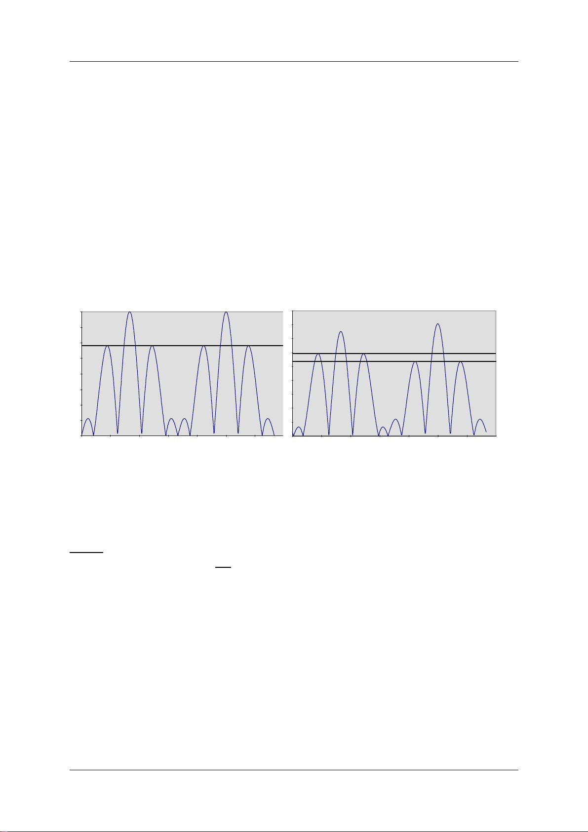
OPERATING MANUALNORMARC 7013
INSTRUMENT LANDING SYSTEM
(Each modulator develops it's own waveform shape due to spreads in insertion phases).
The dynamic maximum point should be approximately -4 volt.
6.4.3.2 SBO waveform checks.
Switch on Course Tx1.
• Connect the Oscilloscope to SBO test connector on Course Tx1 Section via 50 ohm test
cable.
• Set Oscilloscope input mode to DC.
• Check that the waveform resembles the graph below, left.
For best signal resolution on the scope, i t i s advis abl e to set the osci llosc ope i n doubl e sweep
rate and FREE RUN trigger mode ("kissing p atter n" mode). The two hal ves of the 30 Hz waveform will then overlap and look like one waveform when perfect power balance is achieved.
DEMODULATED SBO: 1dB POWER
DEMODULATED SBO: NORMAL IMBALANCE (150Hz<90Hz)
Figure 6-1 SBO Waveforms
6.4.3.3 RF Phase
• Connect the Oscilloscope to SBO test connector on Course Tx1 Section via 50 ohm test
cable.
NOTE:
Set the scope's input mode to DC.
Set the oscilloscope in normal trigger mode such that the waveform below can be observed.
The observed waveform should resemble the NORMAL graph on the left.
©1999 Navia Aviation AS 21833-3.4 Periodic maintenance CAT I and II
6-5
Page 92
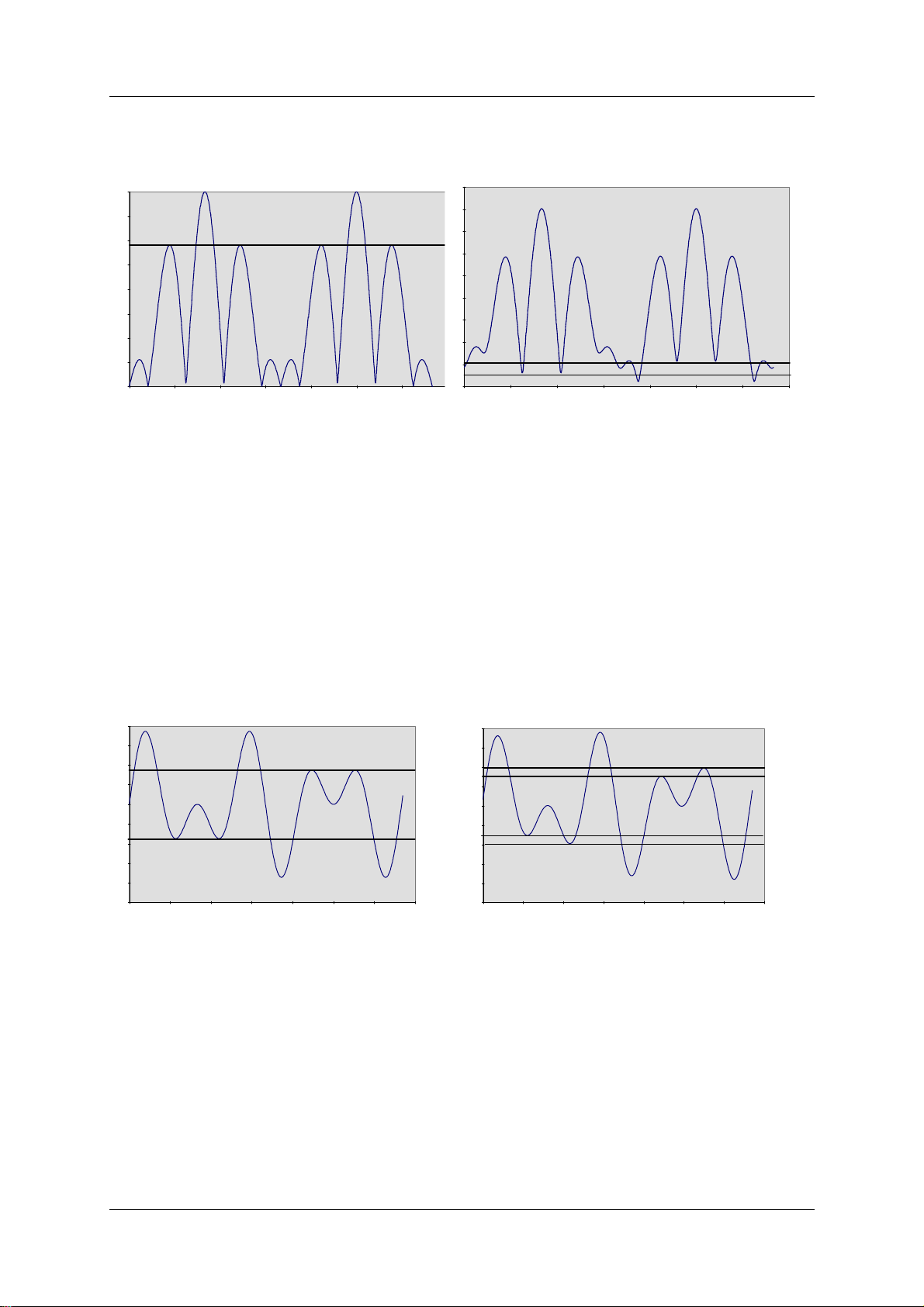
OPERATING MANUAL
INSTRUMENT LANDING SYSTEM
DEMODULATED SBO-SIGNAL: NORMAL DEMODULATED SBO-SIGNAL: 5° RF-PHASE ER-
ROR
NORMARC 7013
Figure 6-2 RF phase check
6.4.3.4 CSB waveform check. LF phase
Switch on Course Tx1.
• Connect the Oscilloscope to CSB test connector on Course Tx1 Section via 50 ohm test
cable.
• Set the Oscilloscope input mode to DC.
Look for the intermediate peak s of the CSB demodul ated wavefo rm. Check t hat the wavefo rm
resembles the graph below (left). The intermediate waveform peaks shal l have the same maximum and minimum level, indicating 90/150 Hz zero phase start.
DEMODULATED CSB: NORMAL DEMODULATED CSB: 10° LF PHASE ERROR
Figure 6-3 LF phase check
6.4.3.5 DDM and SDM check.
Switch on Tx1.
• Connect the Field Test Set to the CSB Cou test connector on the Change Over Section
through a 20 or 30 dB attenuator.
• Use a double shielded 50 ohm coaxial test cable. On the Field Test Set read DDM. The
nominal reading should be 0.0% DDM.
• On the Field Test Set read SDM. The nominal reading should be 40.0%, or the same as the
previous reading/ commissioned value.
6.4.3.6 Ident modulation check.
Periodic maintenance CAT I and II ©1999 Navia Aviation AS
6-6
21833-3.4
Page 93

OPERATING MANUALNORMARC 7013
INSTRUMENT LANDING SYSTEM
Switch on Tx1.
• Connect the Field Test Set to the CSB Cou test connector on the Change Over Section
through a 20 or 30 dB attenuator.
• From the local panel/display or from the RMM program set Cou Ident modulation to CON-
TINUOUS.
• Use a double shielded 50 ohm coaxial test cable. On the Field Test Set read IDENT MOD.
The nominal reading should be 10% MOD, alternatively the same value as previous
recording. (If voice modulation is applied the Ident modulation shall be 5% modulation
depth.)
6.4.3.7 Voice modulation check. (If voice ident is used)
Switch on Tx1.
• Connect the Oscilloscope to CSB test connecto r on Course Tx1 Section via 50 ohm test
cable.
• From the local panel/display connect the audible transducer by command “Set ident
speaker”.
• Listen to the voice message and check that the waveform has a peak amplitude approxi-
mately six times the Ident waveform peak amplitude seen on the oscilloscope.
6.4.4 CSB output power.
a) Course Tx CSB. Switch off the transmitters. Select Tx1 as Main Tx.
• Insert the power meter into the Course CSB output path of the Cabinet. Switch on Tx1.
Read and record the Tx1 power in Table 6-14.
• Change over to Tx2. Read and record the Tx2 power in Table 6-14.
b) Clearance Tx CSB. Switch off the transmitters. Select Tx1 as Main Tx.
• Insert the power meter into the Clearance CSB output path of the Cabinet. Switch on Tx1.
Read and record the Tx1 power in Table 6-14.
• Change over to Tx2. Read and record the Tx2 power in Table 6-14.
6.4.5 Monitor Alarm Limit checks.
After completion and recording of the alarm parameters into Table 6-15, compare and check
that the values are the same as in the previous records.
External RF Signal Generator applied as signal source.
Set the
SELECT
AUTOMATIC/MANUAL switch to MANUAL, the REMOTE/LOCAL to LOCAL and MAIN
to Tx1.
Switch on Course Tx1 and Clearance Tx1.
Check Monitor 1 first.
6.4.5.1 CL DDM ALARM
Apply a test signal from the RF Signal Generator to the CL input connector in the back of the
cabinet.(Disconnect first the sig nal cable from the Monitor network). Adjust the signal to the
same RF level and frequency as the normal signal applied to the monitor.
Modulation shall be: 0.0% DDM, 40.0% SDM.
Verify modulation setting (DDM, SDM) by checking the test signal with the Field Test Set.
©1999 Navia Aviation AS 21833-3.4 Periodic maintenance CAT I and II
6-7
Page 94

OPERATING MANUAL
INSTRUMENT LANDING SYSTEM
NORMARC 7013
Use the Local Display and Keyboard or the RMM Program to display the measured val ues
for CL DDM.
• Change DDM from the generator slowl y toward s 150 Hz do minance unt il a poi nt where th e
letter A (indicates that monitor has an ALARM for the displayed parameter) is shown
beside the measured parameter for Monitor 1.
• Check the new generator DDM value with the Field Test Set.
• Record in Table 6-15 line a).
• Change DDM from the generator slowly towards 90 Hz dominance until a point where the
letter A (indicates that monitor has an ALARM for the displayed parameter) is shown
beside the measured parameter for Monitor 1.
• Check the new generator DDM value with the Field Test Set.
• Record in Table 6-15 line aa).
Repeat the procedure for Monitor 2.
6.4.5.2 CL SDM ALARM
The test setup is the same as in a).
Use the Local Display and Keyboard or the RMM Program to display the measured val ues
for CL SDM
• Increase SDM from the generator slowly until a point where the let ter A (indicates that
monitor has an ALARM for the displayed p arameter) i s shown beside the measur ed par ameter for Monitor 1.
• Check the new generator SDM value with the Field Test Set.
• Record in Table 6-15 line b).
• Decrease SDM from the generator slowly unti l a point where the letter A (indicates that
monitor has an ALARM for the displayed p arameter) i s shown beside the measur ed par ameter for Monitor 1.
• Check the new generator SDM value with the Field Test Set.
• Record in Table 6-15 line bb).
• Repeat the procedure for Monitor 2.
6.4.5.3 CL RF ALARM
The test setup is the same as in a).
Use the Local Display and Keyboard or the RMM Program to display the measured val ues
for CL SDM.
• Decrease slowly RF level on the generator until a point where the letter A (indicates that
monitor has an ALARM for the displayed p arameter) i s shown beside the measur ed par ameter for Monitor 1.
• Record the RF level reading at alarm point in Table 6-15 line c).
Repeat the procedure for Monitor 2.
6.4.5.4 DS DDM ALARM
Apply a test signal from the RF Signal Generator to the DS input connector in the back of the
cabinet.(Disconnect first the sig nal cable from the Monitor network). Adjust the signal to the
same RF level and frequency as the normal signal applied to the monitor.
Modulation shall be: 15.5%DDM, 40.0%SDM.
Verify modulation setting (DDM, SDM) by checking the test signal with the Field Test Set.
Periodic maintenance CAT I and II ©1999 Navia Aviation AS
6-8
21833-3.4
Page 95

OPERATING MANUALNORMARC 7013
INSTRUMENT LANDING SYSTEM
Use the Local Display and Keyboard or the RMM Program to display the measured val ues
for DS DDM.
• Increase DDM from the generator slowly above nominal value unt il a poi nt where the le tter
A (indicates that monitor has an ALARM for the displayed parameter) is shown beside the
measured parameter for Monitor 1.
• Check the new generator DDM value with the Field Test Set.
• Record in Table 6-15 line d).
• Decrease DDM from the generator slowly below nominal value until a point where the lett er
A (indicates that monitor has an ALARM for the displayed parameter) is shown beside the
measured parameter for Monitor 1.
• Check the new generator DDM value with the Field Test Set.
• Record in Table 6-15 line dd).
Repeat the procedure for Monitor 2.
6.4.5.5 NF DDM ALARM
Apply a test signal from the RF Signal Generator to the NF input connector in the back of the
cabinet.(Disconnect first the signal cable from the Near Field Antenna). Adjust the signal to
the same RF level and frequency as the normal signal applied to the monitor.
Modulation shall be: 0.0% DDM, 40.0% SDM.
Verify modulation setting (DDM, SDM) by checking the test signal with the Field Test Set.
Use the Local Display and Keyboard or the RMM Program to display the measured val ues
for NF DDM
• Change DDM from the generator slowl y toward s 150 Hz do minance unt il a poi nt where th e
letter A (indicates that monitor has an ALARM for the displayed parameter) is shown
beside the measured parameter for Monitor 1.
• Check the new generator DDM value with the Field Test Set.
• Record in Table 6-15 line e).
• Change DDM from the generator slowly towards 90 Hz dominance until a point where the
letter A (indicates that monitor has an ALARM for the displayed parameter) is shown
beside the measured parameter for Monitor 1.
• Check the new generator DDM value with the Field Test Set.
• Record in Table 6-15 line ee).
Repeat the procedure for Monitor 2.
6.4.5.6 CLR DDM ALARM
Apply a test signal from the RF Sign al Generat or to the CLR input connector i n the back of the
cabinet.(Disconnect first the sig nal cable from the Monitor network). Adjust the signal to the
same RF level and frequency as the normal signal applied to the monitor.
Modulation shall be: Same as commisioned values DDM and SDM from CLR output of Monitor network.
Verify modulation setting (DDM, SDM) by checking the test signal with the Field Test Set.
Use the Local Display and Keyboard or the RMM Program to display the measured val ues
for CLR DDM.
©1999 Navia Aviation AS 21833-3.4 Periodic maintenance CAT I and II
6-9
Page 96

OPERATING MANUAL
INSTRUMENT LANDING SYSTEM
NORMARC 7013
• Increase DDM from the generat or slowly from nominal value until a point wher e the let ter A
(indicates that monitor has an ALARM for the displayed parameter) is shown beside the
measured parameter for Monitor 1.
• Check the new generator DDM value with the Field Test Set.
• Record in Table 6-15 line f).
• Decrease DDM from the generator slowly from nominal value until a point where the letter
A (indicates that monitor has an ALARM for the displayed parameter) is shown beside the
measured parameter for Monitor 1.
• Check the new generator DDM value with the Field Test Set.
• Record in Table 6-15 line ff).
Repeat the procedure for Monitor 2.
6.4.5.7 CLR SDM ALARM
The test setup is the same as in f).
Use the Local Display and Keyboard or the RMM Program to display the measured val ues
for CLR SDM.
• Increase SDM from the generator slowly until a point where the let ter A (indicates that
monitor has an ALARM for the displayed p arameter) i s shown beside the measur ed par ameter for Monitor 1.
• Check the new generator SDM value with the Field Test Set.
• Record in Table 6-15 line g).
• Decrease SDM from the generator slowly unti l a point where the letter A (indicates that
monitor has an ALARM for the displayed p arameter) i s shown beside the measur ed par ameter for Monitor 1.
• Check the new generator SDM value with the Field Test Set.
• Record in Table 6-15 line gg).
Repeat the procedure for Monitor 2.
6.4.5.8 CLR RF ALARM
The test setup is the same as in c).
Use the Local Display and Keyboard or the RMM Program to display the measured val ues
for CL SDM.
• Decrease slowly RF level on the generator until a point where the letter A (indicates that
monitor has an ALARM for the displayed p arameter) i s shown beside the measur ed par ameter for Monitor 1.
• The nominal level reduction should be 1 dB.
• Record the RF reading at alarm point in Table 6-15 line h).
Repeat the procedure for Monitor 2.
6.4.6 Near Field Monitor delay Set the AUTOMATIC/MANUAL switch to AUTOMATIC, the REMOTE/LOCAL to LOCAL and
MAIN SELECT to Tx1.
Switch on Course Tx1 and Clearance Tx1.
System Status Indicati ons should be NORMAL and SERVICE
Periodic maintenance CAT I and II ©1999 Navia Aviation AS
6-10
21833-3.4
Page 97

OPERATING MANUALNORMARC 7013
INSTRUMENT LANDING SYSTEM
Make an alarm by removing the NF cable to the Cabinet. After the specified delay, the transmitter shall change to Tx2, then after the same time lapse Tx2 shall shut down.
Record in Table 6-16 line a) the measured delay time from cable removal until the standby
transmitter has switched off.
6.4.7 20 seconds inhibit
After shutdown check that an immediate attempted restart of a trans mitter is inhibited at least
20 seconds from the time the standby Tx is shut off.
Record in Table 6-16 line b) the measured time lapse from the standby transmitter has
switched off until the main transmitter is again radiating to the antenna.
6.4.8 Battery maintenance
Check with digital voltmeter that the voltage across the battery terminals is between 27.0 V
and 27.8 V. Record in Table 6-17 line a) the measured voltage.
Switch off the mains 220 V. After approximately 10 minutes battery operation with transmi tter
to air check that the volt age across the bat tery te rminals is not less than 23 V. Record in Table
6-17 line b) the voltage.
Switch back to mains 220 V. After 24 hours check that the battery terminal voltage is again
back between 27.0 to 27.8 V. Record in Table 6-17 line c) the voltage. The 27 V can be monitored from the RMM facility.
6.4.9 Final check LLZ
Check that all electrical contacts and connectors are not loose.
Carry out a visual check outside and inside of the equipment.
Check that all switches and keys are in NORMAL position.
Check that the System lamp status is NORMAL after the switches AUTO/MANUAL and
REMOTE ON/OFF are in AUTO and ON respectively.
©1999 Navia Aviation AS 21833-3.4 Periodic maintenance CAT I and II
6-11
Page 98
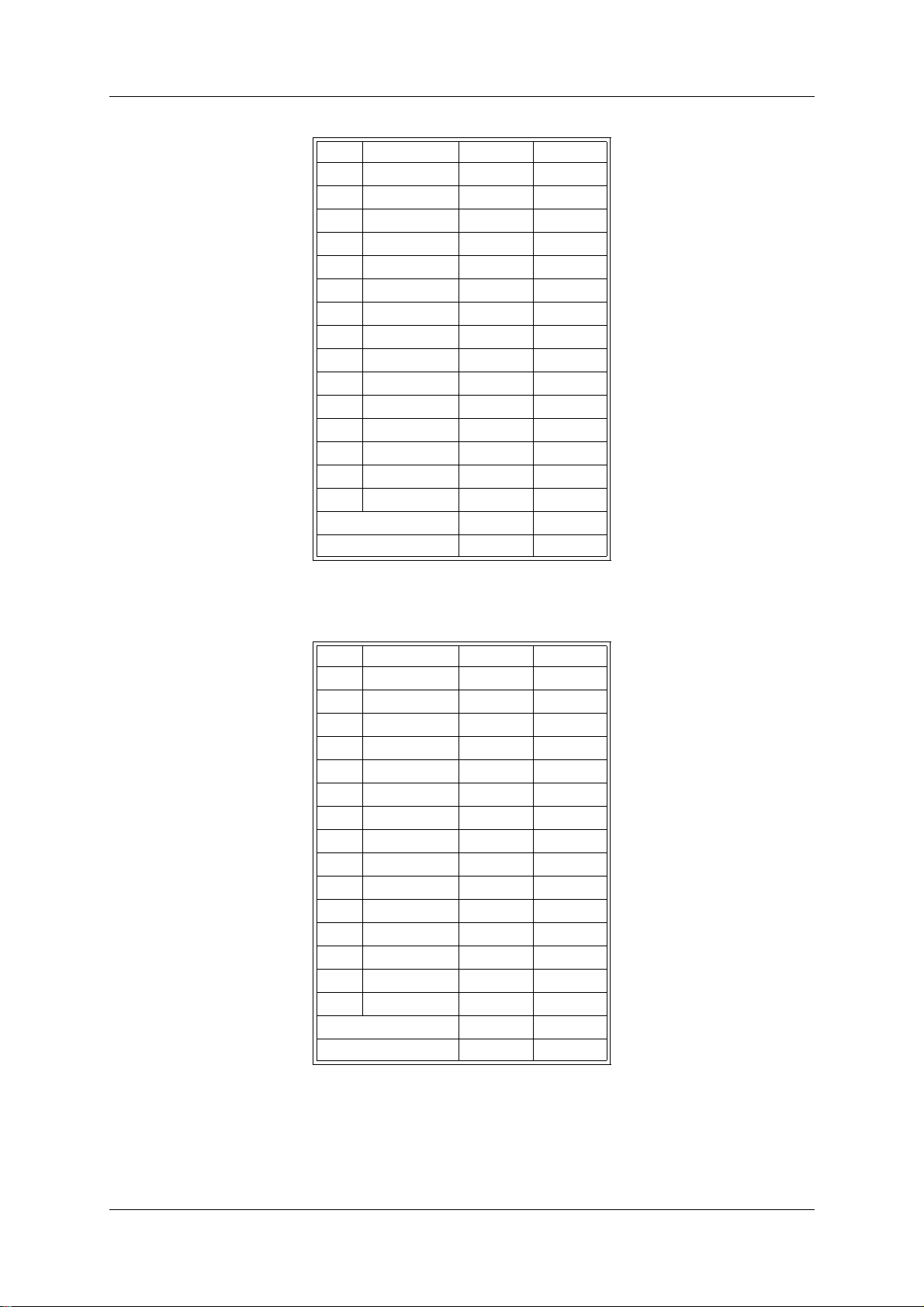
OPERATING MANUAL
NORMARC 7013
INSTRUMENT LANDING SYSTEM
MON1 MON2
CL DDM %
SDM %
RF V
DS DDM %
SDM %
RF V
NF DDM %
SDM %
RF V
CLR DDM %
SDM %
RF V
DF kHz
CL IDENT
CLR IDENT
Self test
DC Loop
Table 6-1 Monitor 1 window (Tx 1 to Air)
MON1 MON2
CL DDM %
SDM %
RF V
DS DDM %
SDM %
RF V
NF DDM %
SDM %
RF V
CLR DDM %
SDM %
RF V
DF kHz
CL IDENT
CLR IDENT
Self test
DC Loop
Table 6-2 Monitor 1 window (Tx 2 to Air)
Periodic maintenance CAT I and II ©1999 Navia Aviation AS
6-12
21833-3.4
Page 99

INSTRUMENT LANDING SYSTEM
OPERATING MANUALNORMARC 7013
MON1 MON2
CL DDM % 0.0 0.0
SDM % 40.0 40.0
RF V 3.0 3.0
DS DDM % 0.0 0.0
SDM % 40.0 40.0
RF V 3.0 3.0
NF DDM % 0.0 0.0
SDM % 40.0 40.0
RF V 3.0 3.0
CLR DDM % 0.0 0.0
SDM % 40.0 40.0
RF V 3.0 3.0
DF kHz 10.0 10.0
CL IDENT OK OK
CLR IDENT OK OK
Self test OK OK
DC-loop OK OK
Table 6-3 Monitor 1 window
(Not for recordings, make a "print screen copy")
Tx1 Tx2
O
O
O Coax Pos
O Main
Table 6-4 Front panel window (displays Tx1 to air)
©1999 Navia Aviation AS 21833-3.4 Periodic maintenance CAT I and II
6-13
Page 100

OPERATING MANUAL
NORMARC 7013
INSTRUMENT LANDING SYSTEM
MON1 MON2
CL DDM % 0.0 0.0
SDM % 40.0 40.0
RF V 3.0 3.0
DS DDM % 0.0 0.0
SDM % 40.0 40.0
RF V 3.0 3.0
NF DDM % 0.0 0.0
SDM % 40.0 40.0
RF V 3.0 3.0
CLR DDM % 0.0 0.0
SDM % 40.0 40.0
RF V 3.0 3.0
DF kHz 10.0 10.0
CL IDENT OK OK
CLR IDENT OK OK
Self test OK OK
DC-loop OK OK
Table 6-5 Monitor 1 window
(Not for recordings, make a "print screen copy")
Tx1 Tx2
O
O
Coax Pos O
MAIN O
Table 6-6 Front panel window (Displays Tx2 to air)
Periodic maintenance CAT I and II ©1999 Navia Aviation AS
6-14
21833-3.4
 Loading...