

Page 1
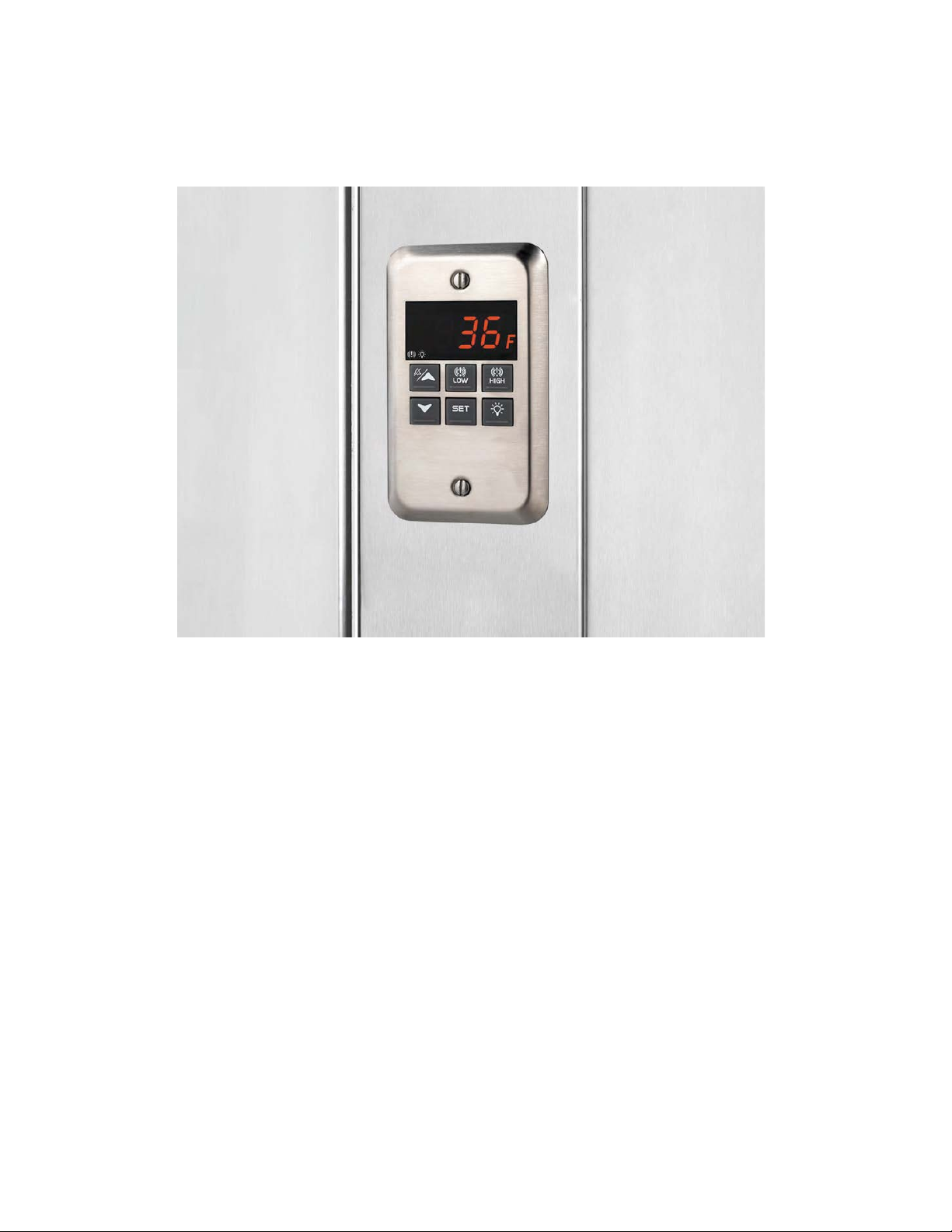
NL708 (XWA11V)
Walk-In Temp / Door /Alarm / Light Module
1. General Description 1
2. General Warnings 1
3. Interface 2
4. Temp Alarms Setting 3
5. Programming 3
6. Light Management 4
7. Installation and Mounting 4
8. Electrical Connections 5
9. Use of the Programming “Hot Key” 5
10. Alarm Signals 5
11. Technical Data 6
12. Connections 6
13. Parameter Map 7
14. Parameter List 8
Quick Sheet 9
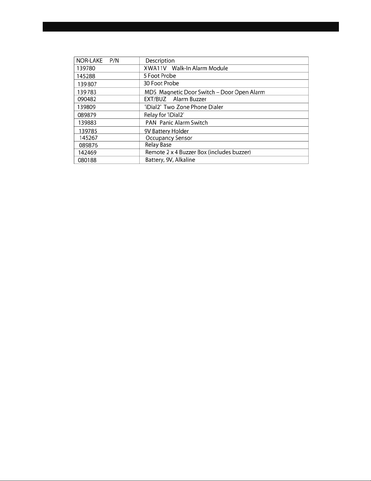
Parts Lists 10
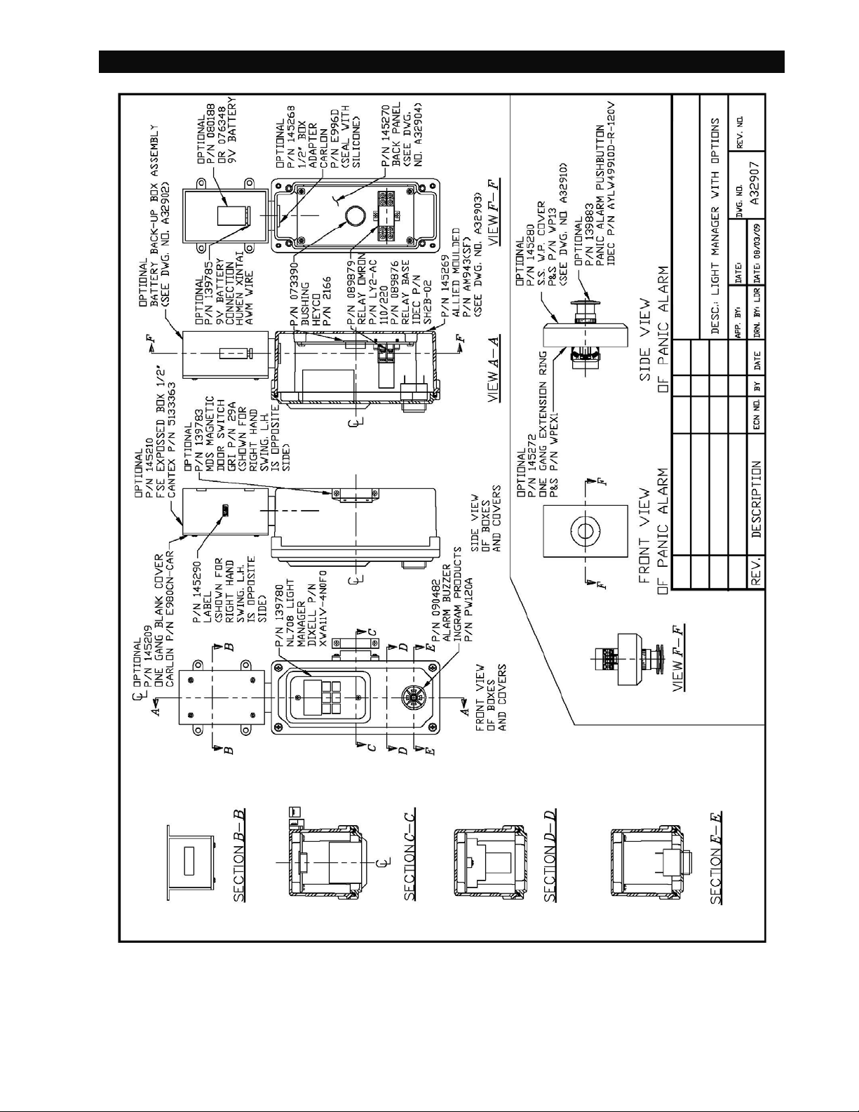
Dwg. No. A32907 Light Manager with Options 11
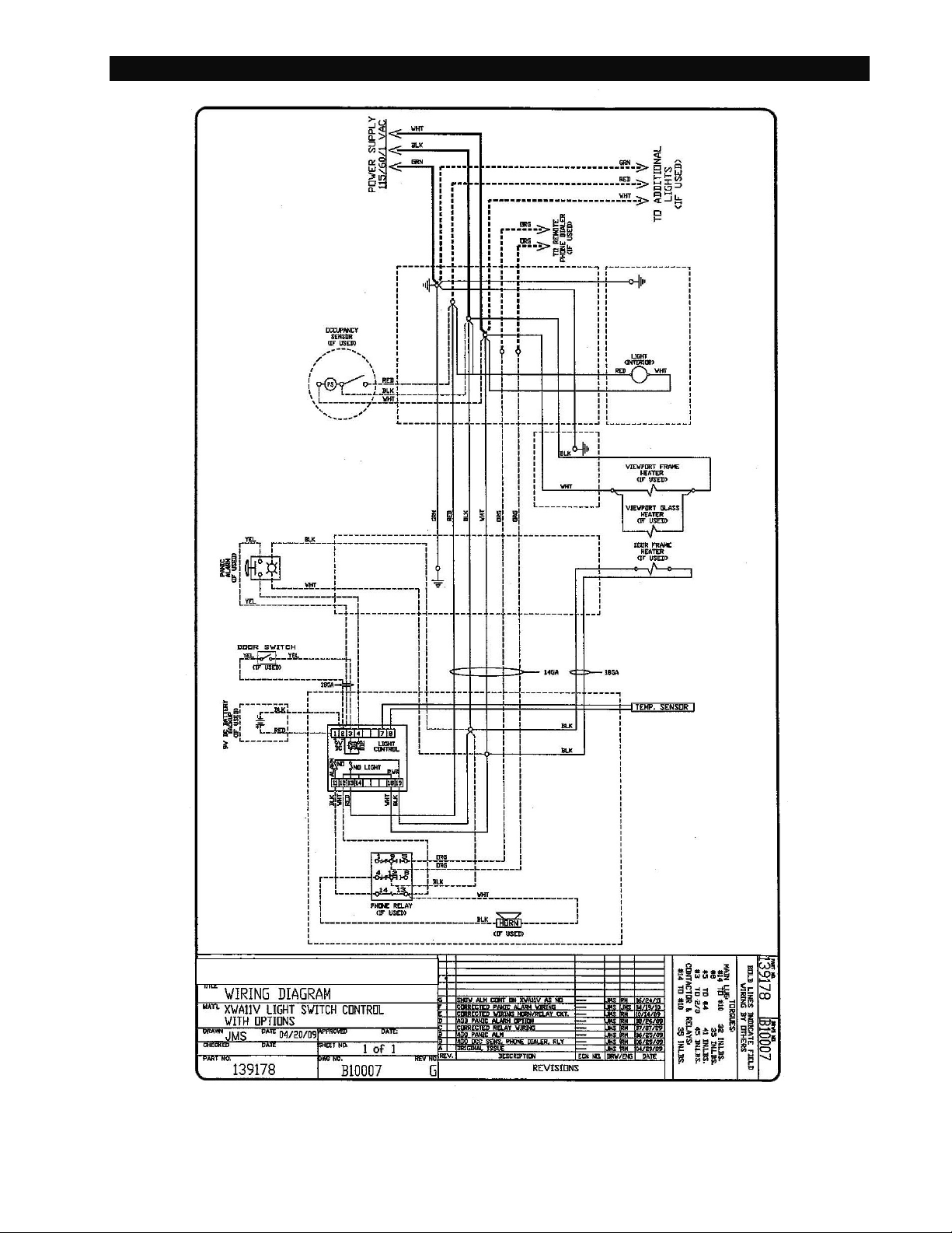
Dwg. No. B10007 Wiring Diagram Light Manager with Options 12
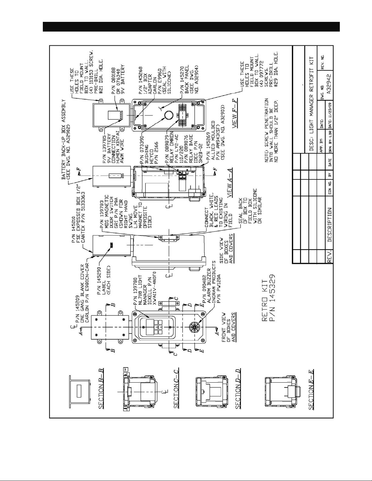
Dwg. No. A32942 Light Manager Retrofit Kit 13
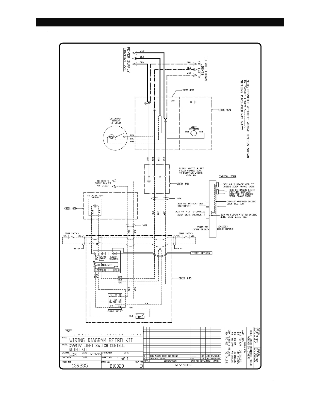
Dwg. No. B10020 Wiring Diagram Retro Kit 14
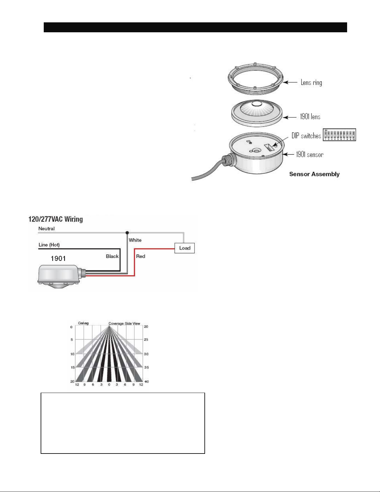
Occupancy Sensor for Light Operation Settings 15
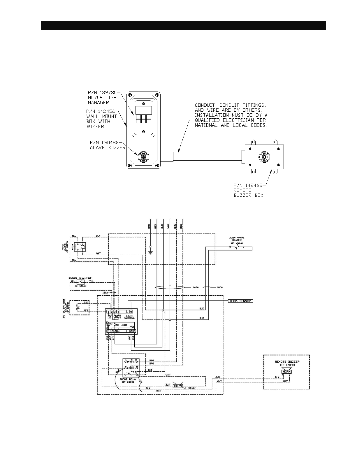
Remote Buzzer Installation 17
01/14 Rev F. 142498
Page 2
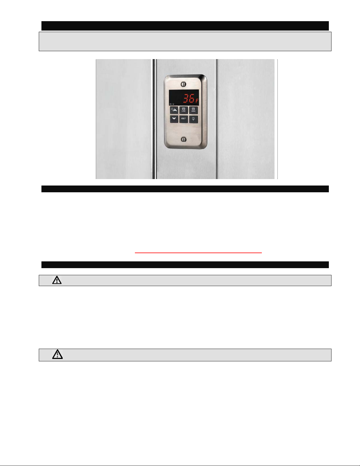
Operating Instructi ons Alarm/Light Module XWA11V
1
XWA11V
Walk-In Temp / Door /Alarm / Light Module
1. GENERAL DESCRIPTION
Model XWA11V, 100x64 m m format, is a microprocessor-based controller, suitable for temperature
monitoring and alarming in a walk -in cooler or freezer. It is provided with two (2) Relay Contacts to control
lights and an external alarm. It is provided with one (1) NTC probe input for temperature measurement. The
unit has 2 Digital Inputs, one for a Door Switch and the 2nd as an option al Panic S witch. See the cata log for
optional accessories. One 5Pin Input allows the user to program the parameter list with a “Hot Key” (see
section 9)
Note: The default settings are listed in the back of this manual. They are set for Coolers (Medium
Temp). For Freezers (Low Temp) you MUST Change th e ALL and ALU settings. See Section 4.0
2. GENERAL WARNINGS
2.1 PLEASE READ BEFORE USING THIS MANUAL
• This manual is part of the product and should be kept close to the instrument for easy and quick reference.
• The instrument shall not be used for purposes different from those described hereunder. It cannot be used
as a safety device.
• Check the application limits before proceeding.
Note: If equipped with a battery backup, the battery must be installed after the walk-in has reached its
operating temperature.
2.2 SAFETY PRECAUTIONS
• Check if the supply voltage is correct before connecting the instrument.
• Do not expose the back of the instrument to water or moisture: use the controller only within the operating limits
avoiding sudden temperature changes with high atmospheric humidity to prevent the formation of condensation.
• Warning: disconnect all electrical connections before performing any maintenance operation.
• Fit the probe where it is not damaged by the end-user. The instrument must not be opened.
• In case of failure or faulty operation send the instrument back to the distributor (see address) with a detailed
description of the fault.
• Consider the maximum current that can be applied to each relay (see Technical Data).
• Ensure that the wires for probes, loads and the power supply are separated and far enough from each other, without
crossing or intertwining, or you may get bad temperature readings.
• Be sure to seal any J-box with RT sealant to prevent cold and moisture intrusion.
01/14 Rev F. 142498 Page
Page 3
Operating Instructi ons Alarm/Light Module XWA11V
2
3. INTERFACE
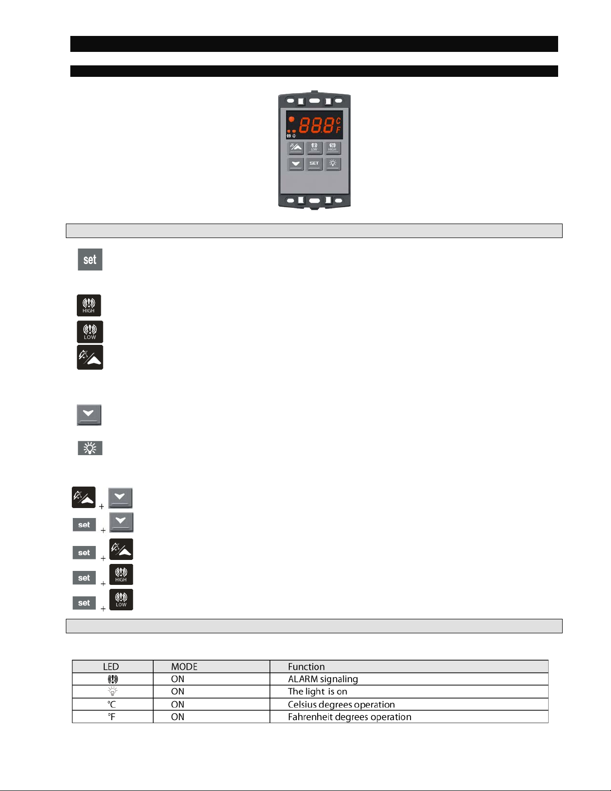
3.1 KEY FRONT PANEL OPERATION
In Programming Mode press to select a parameter or to confirm an operation.
Press and hold this key for more than 5 s to turn the controller OFF.
Press and hold this key for more than 1 s to turn the controller back ON.
Press to see the HIGH Temp ALARM (ALU parameter)
Press to see the LOW Temp ALARM (ALL parameter)
In Programming Mode press to browse parameter codes.
Press to increase the displayed value.
Press to mute the buzzer (+ relay) when an ALARM is happening.
Hot key programming: with the instrument on, insert the hot key and then press the UP
button.
In Programming Mode press to browse parameter codes.
Press to decreases the displayed value.
Switch ON and OFF the light of the cold room
KEY COMBIN ATIONS: PRESS SIMULTANEOUSLY
To lock and unlock the Keyboard.
To enter the Programming Mode.
To exit the Programming Mode.
To enter a new value for the HIGH Temp ALARM (ALU).
To enter a new value for the LOW Temp ALARM (ALL).
3.2 USE OF LEDS
Each LED function is described in the following table:
01/14 Rev F. 142498 Page
Page 4
Operating Instructi ons Alarm/Light Module XWA11V
3
4. TEMP ALARM SETTINGS
4. TEMP ALARMS SET T I NG
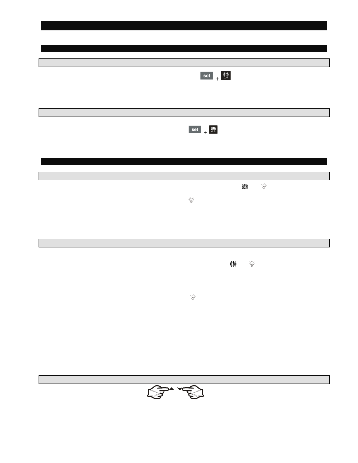
4.1 HOW TO SET THE MIN TEMPERATURE ALARM
• To modify the minimum (LOW) Temp ALARM: hold the keys pressed for 3 s until the
minimum Temp alarm is displayed.
• Change the value using the UP and DOWN keys.
• Press the SET key to confirm the new value and exit.
4.2 HOW TO SET THE MAX TEMPERATURE ALARM
• To modify the max (HIGH) Temp ALARM: hold the
alarm is displayed.
• Change the value using the UP and DOWN keys.
• Press the SET key to confirm the new value and exit.
5. PROGRAMMING
5.1 HOW TO CHANGE A PARAMETER VALUE MAIN MENU
1. Enter the Programming Mode by pressing the SET and DOWN key for 3s ( and will start blinking).
2. Select the required parameter. By using the UP or DOWN KEY
3. Press the “SET” key to display its value (now only the
LED is blinking).
4. Use “UP” or “DOWN” to change its value.
Press “SET” to store the new value and move to the following parameter.
To exit: Press SET + UP or wait 15 s without pressing a key.
NOTE: the set value is stored even when the procedure is exited, by waiting the time-out to expire.
5.2 THE HIDDEN MENU (PR2)
The hidden menu includes all the parameters of the instrument.
5.2.1 HOW TO ENTER THE HIDDEN MENU (PR2)
1. Enter the Programming Mode by pressing the Set + down key for 3s (
2. When a parameter is displayed, relea se an d re-press the SET + down for more than 7s.
3. The Pr2 label will be displayed immediately followed from the HY parameter. NOW YOU ARE IN THE
HIDDEN MENU.
4. Select the required parameter as above
5. Press the “SET” key to display its value (Now only the
6. Use “UP” or “down” to change its value.
7. Press “SET” to store the new value and move to the following parameter.
To exit: Press SET + up or wait 15s without pressing a key.
NOTE: the set value is stored even when the procedure is exited by waiting the time-out to expire.
5.2.2 HOW TO MOVE A PARAMETER FROM THE HIDDEN MENU TO THE FIRST LEVEL AND
VICEVERSA
Each parameter present in the HIDDEN MENU can be removed or put into “THE FIRST LEVEL” (user level)
by pressing “SET + down”.
In HIDDEN MENU when a parameter is present in First Level the decimal point LED is on.
5.3 HOW TO LOCK THE KEYBOARD
1. Keep pressed for more than 3s the UP and DOWN keys.
2. The “POF” message will be displayed and the keyboard will be locked. At this poi nt it will be poss ib le
only to see the Set Point or the MAX or MIN Temp stored
3. If a key is pressed more than 3s the “POF” message will be displayed.
LED is blinking).
keys pressed for 3 s until the max Temp
and starts blinking).
01/14 Rev F. 142498 Page
Page 5
Operating Instructi ons Alarm/Light Module XWA11V
4
5.4 TO UNLOCK THE KEYBOARD
Keep pressed together for more than 3s the UP and DOWN keys. The “PON” message is displayed
6. LIGHT MANAGEMENT
6.1 TIMED REGULATION: I1L = Y
With i1L = y the light remains on at least for the LHt parameter.
The LHt timer is re-initialized every time the light button is pushed.
With LHt=0 the light remains on until the light button is pushed again.
The light is switched on every time one of the following conditions happens:
• the door is open (i1F = dor)
• the presence sensor is activated (i2F = LHt)
• the light button is pushed
The light is switched off when all the following conditions happen:
• the LHt timer is exhausted
• the door is closed (i1F = dor)
• the presence sensor is de-activated (i2F = LHt)
• Light button regulation: i1L = n
The lights will flash (for 2 minutes) every 20 seconds for the FLH time (0-5 min) at the end of the LHt time
as a warning that the lights are about to turn off (for incandescent and LED lights only).
The light button has a higher priority tha n d igital inputs therefore:
- if the light was switched on by button the digital input can not modify its status.
- if the light was switched on by digital input, the light button can modify its status.
7. INSTALLATION AND MOUNTING
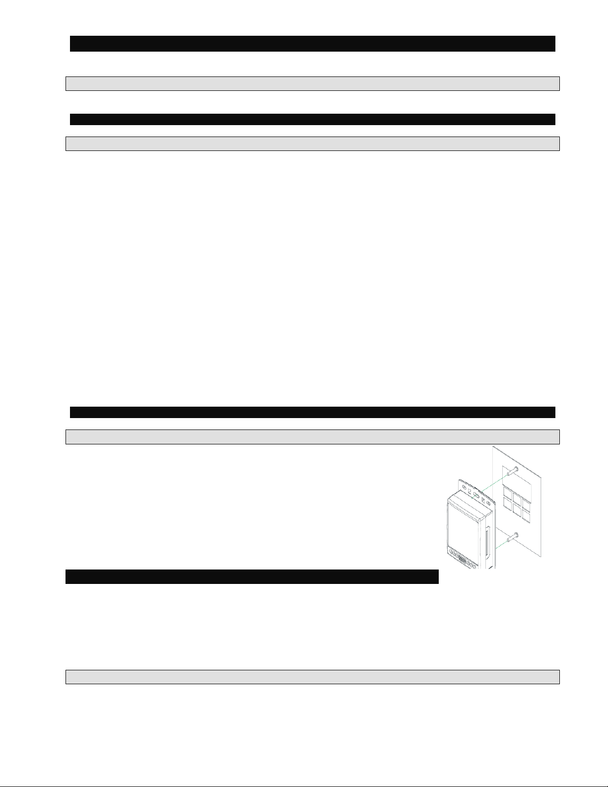
7.1 MOUNTING OF XWA11V – PR10000
The XWA11V must be mounted on vertical panel, in a J-Box (Steel City PN 683711/2) or equal or wall mounted using an appropriate enclosure.
The Ambient Temp range for correct operation is 32 – 131°F (0-55°C). Avoid
installation in places subject to strong vibrations, corrosive gases, excessive dirt or
humidity. The same recommendations apply to probes.
8. ELECTRICAL CONNECTIONS
The instrument is provided with ¼” fast-on terminal blocks to connect cables with a cross section up to .110”
for the digital and analog inputs. Relays and power supply have a Fast-on connection (.250”). For supply
connections, use 14 AWG or larger copper or CU wire only rated at least 90˚C (194˚F). Before connecting
cables make sure the power supply complies with the instrument requirements. Separate the probe cables
from the power supply cables, from the outputs and the power connections. Do not exceed the maximum
current allowed on each relay and in case of heavier loads use a suitable external relay.
N.B. Maximum current allowed for all the loads is 15A.
8.1 PROBE CONNECTIONS
The probe shall be mounted with the bulb upwards to prevent damages due to casual liquid infiltration. It is
recommended to place the thermostat probe away from air streams to correctly measure the average room
temperature. The probe can be extended up to 300 ft. Check calibration when running long lengths over
100ft.
01/14 Rev F. 142498 Page
Page 6
Operating Instructi ons Alarm/Light Module XWA11V
5
9. USE OF THE PROGRAMMING “HOT KEY “
9.1 HOW TO PROGRAM A HOT KEY FROM THE INSTRUMENT (UPLOAD)
1. Program one controller with the front keypad.
2. When the controller is ON, insert the “Hot key” and push UP key; the "uPL" message appears followed a
by flashing “End”
3. Push “SET” key and the End will stop flashing.
4. Turn OFF the instrument remove the “Hot Key”, then turn it ON again.
NOTE: the “Err” message is displayed for failed programming. In this case push UP key again if you want to
restart the upload again or remove the “Hot key” to abort the operation.
9.2 HOW TO PROGRAM AN INSTRUMENT USING A HOT KEY (DOWNLOAD)
1. Turn OFF the instrument.
2. Insert a programmed “Hot Key” into the 5 PIN receptacle and then turn the Controller ON.
3. Automatically the parameter list of the “Hot Key” is downloaded into the Controller memory, the “doL”
message is blinking followed a by flashing “End”.
4. After 10 seconds the instrument will restart working with the new parameters.
5. Remove the “Hot Key”.
NOTE the message “Err” is displayed for failed programming. In this case turn the unit off and then on if you
want to restart the download again or remove the “Hot key” to abort the operation.
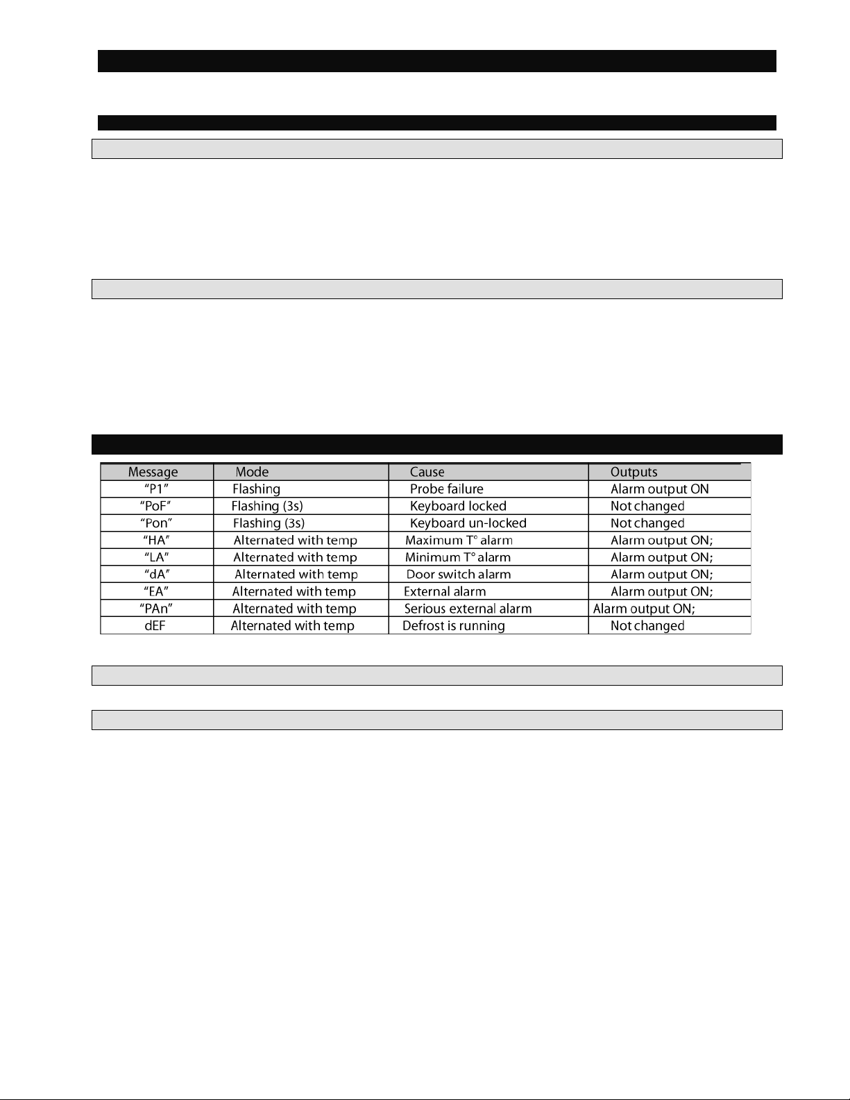
10. ALARM SIGNALS
The alarm message is displayed until the alarm condition is reset.
10.1 SILENCING BUZZER
Once the alarm signal is detected the buzzer can be silenced by pressing the UP key.
10.2 ALARM RECOVERY
Probe alarms: “P1” (probe1 faulty), “P2”; they automatically stop 10s after the probe restarts normal
operation. Check connections before replacing the probe.
T° alarms “HA” and “LA” automatically stop as soon as the thermostat T° returns to normal values or when
the defrost starts.
Door switch alarm “dA” stops as soon as the door is closed.
External alarms “EAL”, “BAL” stops as soon as the external digital input is disa bled.
01/14 Rev F. 142498 Page
Page 7
Operating Instructi ons Alarm/Light Module XWA11V
6
11. TECHNICAL DATA
Housing: self extinguishing ABS
Case: face 100x64 mm; depth 45.5mm
Mounting: J-box or wall-mount in suitable enclosure
Frontal protection: IP65
Connections: ¼” fast-on for power, 1/8” fast-on for probes and Digital Inputs
Power supply: 120Vac
Power absorption: 4VA max .
Ambient Temperature: 32-131°F (0-55°C)
Display: 3 digits, red LED, 14,2 mm high.
Inputs: 1 NTC probe
Digital inputs: 2 free voltages
Relay outputs: Relay Contacts
Light: relay SPST 15A, 120Vac;
Alarm: relay SPST 8A, 120Vac
Other output: alarm buzzer
Data storing: on the non-volatile memory (EEPROM).
Measuring and regulation range:
NTC probe: -40÷110°C (-58÷230°F)
Resolution: 1 °F
Accuracy : ±1 °F
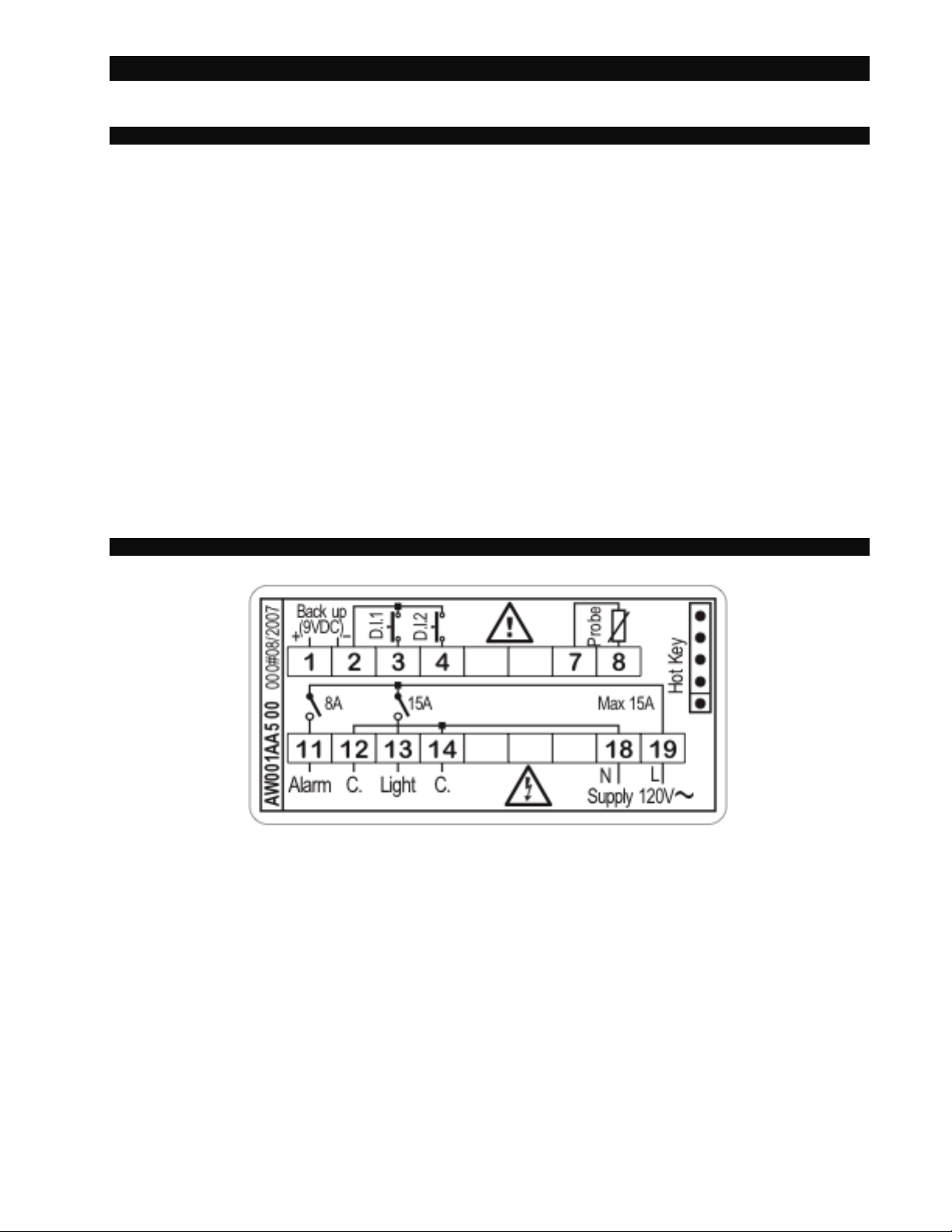
12. CONNECTIONS
± 10%, optional 230Vac ± 10% MAX 15A
Power supply: 120Vac +/- 10% 15A MAX current
01/14 Rev F. 142498 Page
Page 8
Operating Instructi ons Alarm/Light Module XWA11V
7
LABEL
DESCRIPTION
VALUE
LEVEL
RANGE
ot
Thermostat probe calibration
0
Pr2
[-21°F - 21°F]
CF
Temperature measurement unit
F
Pr2
°C - °F
rES
Resolution (only for °C)
in
Pr2
dE - in
UT
Display update
60
Pr2
0 - 255 (sec.)
OnF
Off function enabling
y
Pr2
n - Y
ALU
High temperature alarm setting (med temp / low temp)
50 / 30
Pr1
ALL-302° F
ALL
Low temperat ure alarm setting (med temp / low temp)
30 / -20
Pr1
°-58 - ALU
AFH
Temperature al ar m dif fer e nti al
2
Pr2
1°F - 45°F
ALd
Temperature al ar m del ay
30
Pr1
0 - 255 (min.)
dAo
Delay of temperature alarm at start-up
1.3
Pr2
0.0 - 24.0 Hrs.
EdA
Alarm delay at the end of defrost
30
Pr2
0 - 255 (min.)
dot
Delay of temperature alarm after clos ing the door
15
Pr2
0 - 255 (min.)
LHt
Light timer
15
Pr1
0 - 255 (min.)
FLH
Light Flashi ng Timer (time before light goes out that it will flash) (for incandescent & LED lights only)
2
Pr1
0 - 5 (Min)
doA
Open door alarm delay
15
Pr1
0 - 255 (min.)
oA1
First relay configuration
ALr
Pr2
ALr - LHt - OnF
oA2
Second relay configuration
LHt
Pr2
ALr - LHt - OnF
AOP
Alarm relay polarity
oP
Pr2
OP - CL
i1P
Digital input 1 polarity
CLoP
Pr2
OP - CL
i1L
Door switch to turn light ON
y
Pr2
n - Y
i1F
Digital inp ut 1 operating mode
dor
Pr2
EAL - dor - dEr - LHt
i2P
Digital input 2 polarity
cL
Pr2
OP - CL
i2F
Digital inp ut 2 operating mode
PAn
Pr2
EAL - Pan - dFr - LHt
did
Time interval /delay for digital input alarm
0
Pr2
0 - 255 (min.)
tbA
Alarm relay disabling
n
Pr2
n - Y
PbC
Kind of probe
ntc
Pr2
PtC - ntC
dP1
Real temperature Probe 1
Pr2
(probe value)
rEL
FW release
Pr2
read only
Ptb
Parameter m ap
Pr2
read only
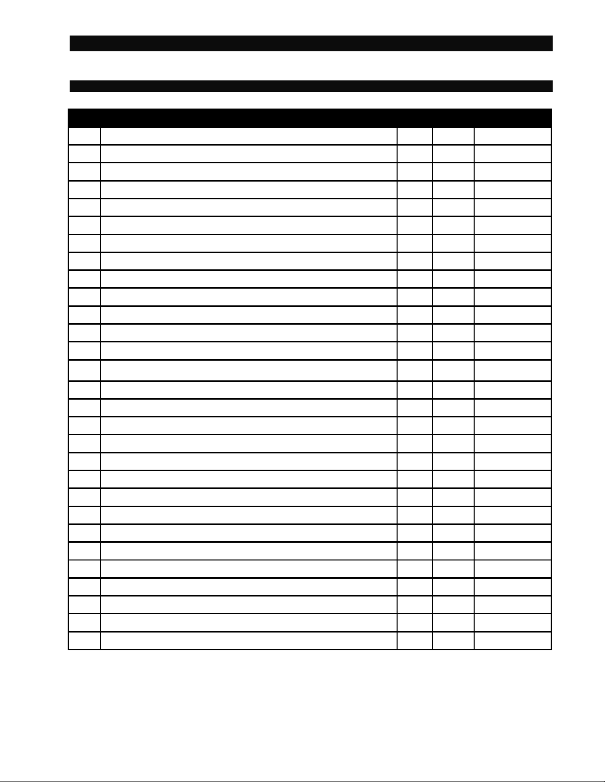
13. PARAMETER MAP
01/14 Rev F. 142498 Page
Page 9

Operating Instructi ons Alarm/Light Module XWA11V
8
14. PARAMETER LIST
Ot Thermostat probe calibration: (-12.0
÷12.0°C/ -21÷21°F) allows to adjust possible offset of the
thermostat probe.
CF T measurement unit: °C = Celsius; °F = Fahrenheit. When the measurement unit is changed the
Set Point and the values of some parameters have to be modified.
rES Resolution (for °C): (in = 1°C; dE = 0.1 °C) allows decimal point display.
Ut Display update: The time delay of the T readout (0÷255s)
onF Off function enabling: n = off function disabled; y = off function enabled;
ALU High T° alarm setting: (ALL
÷ 150°C or 302°F);
when this T° is reached and after the ALd delay time the HA alarm is enabled.
ALL Low T° alarm setting: (- 50°C or -58°F
when this T° is reached and after the ALd delay time, the LA alarm is enabled,.
AFH T° alarm differential: (0,1÷25,5°C; 1÷45°F) differential for T° alarm Set Point and fan regulation
Set Point, always a positive value
ALd T° alarm delay: (0÷255 min) time interval between the detection of an alarm condition and the
corresponding alarm signaling.
dAO Delay of T° alarm at start-up: (0min÷23h 50min) time interval between the detection of the T°
alarm condition after the instrument power on and the alarm signaling.
EdA Alarm delay at the end of defrost: (0
÷255 min) Time interval between the detection of the T°
alarm condition at the end of defrost and the alarm signaling.
dot Delay of T° alarm after closing the door: (0
condition after closing the door.
LHt Light timer: (0-255 min) The time the light will stay on after pressing the light switch on the
keyboard.
FLH Light Flashing: (0-5 min) The light will “dou ble flash” every 20 seconds dur ing the FLH time period
before turning off after the LHt time. (For incandescent and LED lights only.)
doA Open door alarm delay:(0÷255 min) delay between the detection of the open door condition and
its alarm signaling: the flashing message “dA” is displayed.
oA1 First relay configuration: (14-15): ALr = alarm; LHt = light; onF = on/off relay
oA2 Second relay configuration: (14-16): ALr = alarm; LHt = light; onF = on/off relay
AOP Alarm relay polarity: cL = closing contacts ; oP = ope n ing contac ts .
i1P Digital input 1 polarity (1-2): CL : the digital input is activated by closing the contact;
OP: the digital input is activated by opening the contact
i1L Door switch to turn light ON(1-2): (y / no) To turn the light ON automatically when the door is
open. The light will turn off based on LHt . Keyboard switch must be turned ON first.
i1F Digital input 1 operating mode(1-2): EAL = external alarm; dor = door switch; dFr = A defrost is
running; LHt = keep light ON (signal from occupancy sensor) override LHt.;
i2P Digital input 2 polarity (1-3): CL : the digital input is activated by closing the contact;
OP: the digital input is activated by opening the contact
i2F Digital input 2 operating mode: configure the digital input function:
EAL = External alarm;
PAn =Panic alarm;
dFr = A defrost is running; (need external CT’s)
LHt = Keep light ON (signal from occupancy sensor) overrides LHt.
did Time interval/delay for digital input alarm:(0
“did” parameter defines the time delay between the detection and the successive signaling of the
alarm.
tbA Alarm relay & Buzzer disabling: (y ; no)
Pbc Type of probe (PTC, NTC)
dP1 Probe 1 T
rEL Software release for internal use.
Ptb Parameter table code: read only.
÷ ALU)
÷255 min) Time delay to signal the T° alarm
÷255 min.) If I2F=EAL or PAn (external alarms),
01/14 Rev F. 142498 Page
Page 10
Operating Instructi ons Alarm/Light Module XWA11V
9
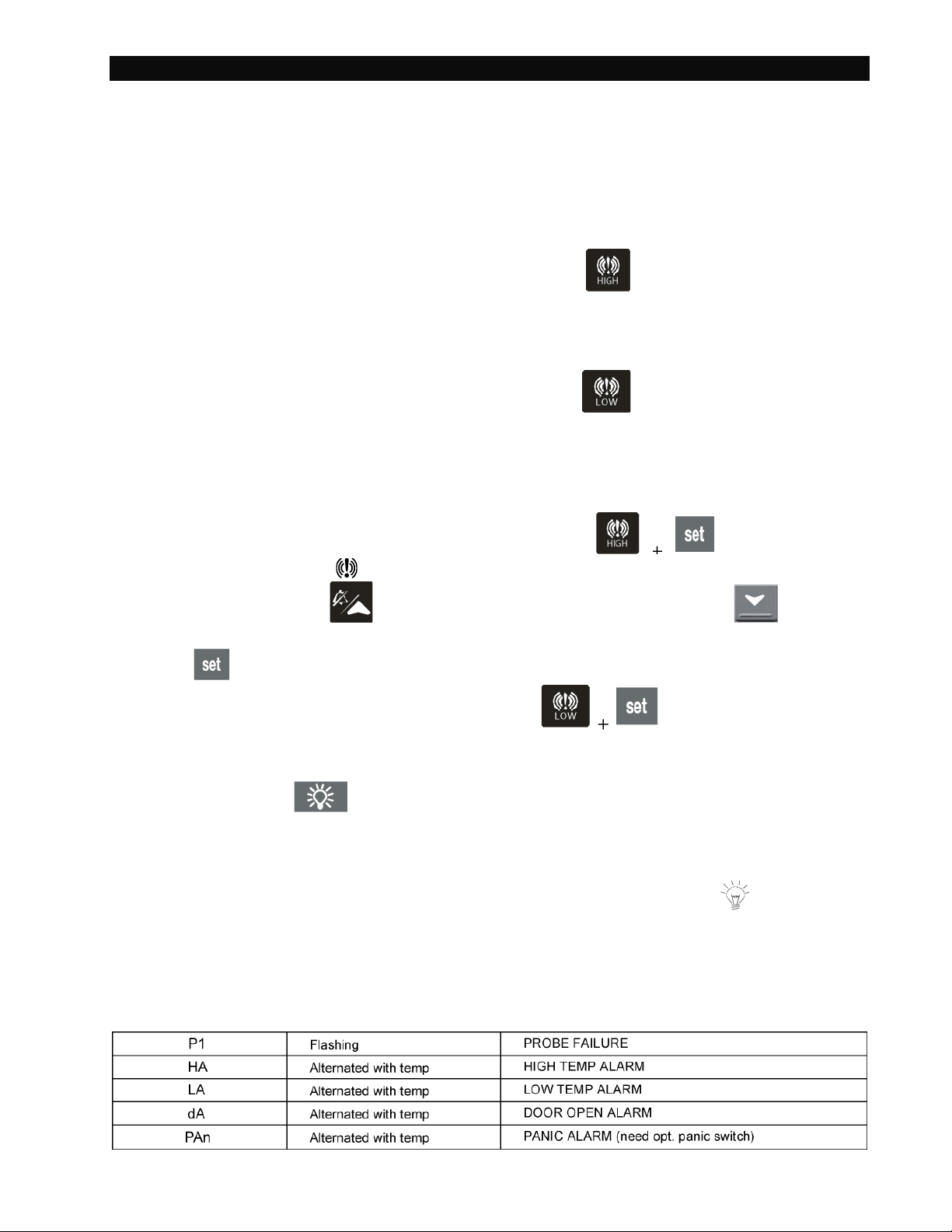
QUICK SHEET
XWA11V Walk-in Alarm / Door / Alarm / Light Unit Operation Manual
In Normal Operation the Indicator will display the temperature. 36° F
CHECK ALARM SETPOINTS (Cooler HA = 50°F, LA = 30°F / Freezer HA = 30°F, LA = -20°F)
To SEE the HIGH Alarm Set Point Press and release the Key, It will display the High
Set Point for 5 seconds. The Temp alarm will go ON if the temp exceeds the Set Point after
15 minutes. The display will read HA alternating with the Temp.
To SEE the LOW Alarm Set Point Press and release the Key it will display the Low
Set Point for 5 seconds. The Temp alarm will go ON if the temp exceeds the Set Point after
15 minutes. LA, alternati ng w it h the Temp.
CHANGE ALARM SETPOINTS
1. To Change the HIGH Alarm Set Point Press BOTH the for 7 seconds
and the LED above the will blink.
2. Release and scroll UP to adjust the Set Point up, or Scroll DOWN to adjust
the Set point down.
3. Press
to confirm the change.
4. For Low Set Point repeat the procedure with the
LIGHT OPERATION
Press the light switch
to turn ON the inside light; it will automatically go OFF after 15
minutes.
DOOR SWITCH
If the door switch is used opening the door will automatically turn the light ON, and will
automatically go OFF after 15 minutes.
If the Door is left open longer than 15 minutes the DOOR Alarm will go off, dA alternating
with the temperature reading.
ALARM SIGNAL S
01/14 Rev F. 142498 Page
Page 11
Operating Instructi ons Alarm/Light Module XWA11V
10
Walk-In Alarm System
01/14 Rev F. 142498 Page
Page 12
Operating Instructi ons Alarm/Light Module XWA11V
11
01/14 Rev F. 142498 Page
Page 13
Operating Instructi ons Alarm/Light Module XWA11V
12
01/14 Rev F. 142498 Page
Page 14
Operating Instructi ons Alarm/Light Module XWA11V
13
01/14 Rev F. 142498 Page
Page 15
Operating Instructi ons Alarm/Light Module XWA11V
14
01/14 Rev F. 142498 Page
Page 16
Operating Instructi ons Alarm/Light Module XWA11V
15
1901000005
1901000007
WARNINGS AND CAUTIONS:
Occupancy Sensor for Light Operation
Installation:
1) Determine best location for sensor. Ideal
location is above door to monitor traffic entering
the work area. Limit false tripping by keeping
away from fans and vent ports.
2) Set the DIP switches to match operating
requirements. (Setting options are on next
page) Record setting and date on last sheet on
this instruction sheet and keep for reference.
3) Thread the ½ NPT arm into junction box or into
light fixture housing.
4) Connect the line voltage, neutral and load wires
to the sensor leads as shown in wiring
Diagram.
5) With lens off, temporarily cover sensor with
towel or aluminum foil. Apply power and the
sensor will turn ON for up to 2 minutes and
automatically turn OFF. Remove towel or
aluminum foil and wave hand in front of sensor.
Determine if the ON time is adequate for
application and/or make any final adjustments to DIP switches.
6) Attach the Lens as shown in the sensor assembly drawing.
1901000007: 24’ dia at 20’ - 40’
Weight: 0.28 lbs [130 grams]
Low Bay
Sensor
High Bay
Sensor
Temperature:
Min: -40 °F [-40 °C]
Max: 131 °F [55 °C]
Electrical Connection:
½” conduit connection
13 ½” 18 AWG wire
Wire temperature 105 deg C max *
• All installation must comply with local and National
Electrical Codes.
• The manufacturer assumes no responsibility for
improper installation or application.
cULus Wet location – Indoor Use Only
• Turn off electricity at the breaker or fuse box before
installation.
PIR Sensitivity (Switches 1 – 2)
Specifications:
Voltage: 120 / 277 VAC @ 60 Hz
Load: 120 VAC / 0- 800W ballast
277 VAC / 0-1200W ballast
Time Delay: 15 seconds – 30 minutes
Coverage:
1901000005: 24’ dia at up to 20’
*Some incandescent fixtures may re q u ire
higher temperature wires. Remote mounting
or adding fiberglass sleeves over the wires
may be required.
Approval Standards: IP65
01/14 Rev F. 142498 Page
Page 17
Operating Instructi ons Alarm/Light Module XWA11V
16
Settings
1
2
High
Normal
X
Medium
X
Low
X
X
Settings
3 4 5 6 7
15 Seconds
X X X X X
5 Minutes
X X X X
10 Minutes
X X X
15 Minutes
X X
20 Minutes
X
30 Minutes
Settings
8 9 10
OFF
n/a
n/a
ON
X
n/a
n/a
Date:
1 2 3 4 5 6 7 8 9
10
n/a
n/a
n/a
n/a
Note: The sensor is pre-set at
The factory setting (Normal) is suitable for most applications, but it may be necessary to adjust the PIR
sensitivity if there is any environmental interference causing false triggers or if sensitivity needs to be
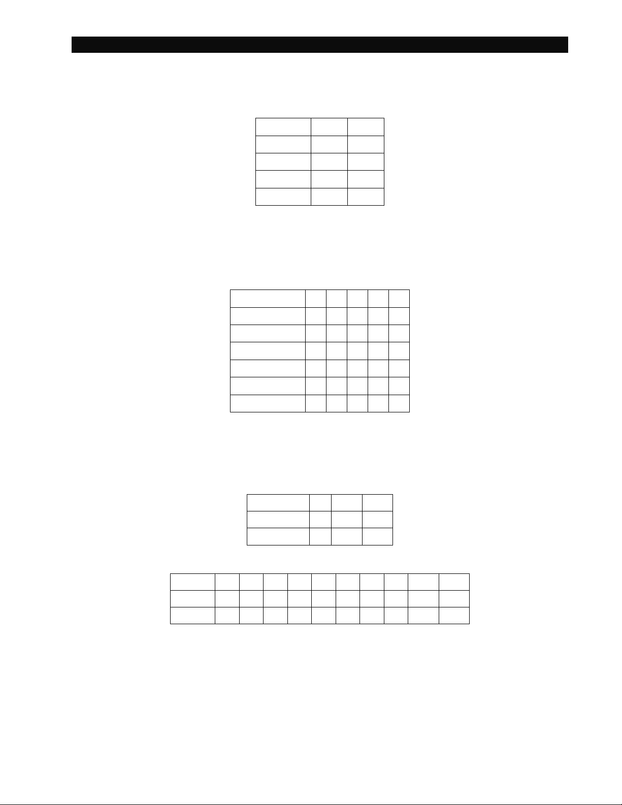
increased for your particular application. Use DIP switches 1 & 2 to adjust sensitivity.
Sensitivity
the factory to meet the
requirements of most
applications. Sensor factory
pre-sets are bold. “X”
indicates switch in the ON
position.
ON Time Timer (Switches 3 – 7)
Use DIP switches 3 to 7 to adjust the ON time duration. Note: will restart timer every time motion it detected.
Timer Settings
Override (Switch 8)
The override disables the occupancy control feature of the sensor module. When occupancy control is
disabled, the load remains ON as long as the sensor is powered.
Override
Please mark your current settings for reference.
Remote Buzzer Box Installation
01/14 Rev F. 142498 Page
Page 18
Operating Instructi ons Alarm/Light Module XWA11V
17
Installation:
1. Mount the remote buzzer box in the location desired.
2. Drill the appropriate size hole for the conduit fitting into the Wall Mount Box P/N 142456.
3. Conduit, conduit fittings, and wire are by others.
Installation must be by a qualified electrician per the applicable national and local codes.
4. Connect a black wire to terminal #4 and a white wire to terminal #13 of the Phone Relay in the Wall
5. Mount Box.
01/14 Rev F. 142498 Page
 Loading...