

Page 1

LIGHTED CHAMBERS
Installation, Operation and
Maintenance Instructions
GENERAL
Inspection
Location
Installation
Door Alignment 3
Shelf Installation 4
Remote Contacts 4
RS485 Port (optional) 4
Internal Outlet (optional) 4
Access Port (optional) 4
Humidity Installation (optional)
Drain Installation
Electrical
Glycerin Well Assembly
OPERATION
2
2
2
3
5
5
6
6
6
MAINTENANCE
Periodic Cleaning
Cleaning the Humidifier
Battery, fuse, bulbs and lighting levels
Trouble shooting guide
Wiring Diagram
7
7
7
9
11
12
06/11 Rev. A 147286
Page 2

GENERAL
INTENDED USE
Designed to meet the demanding requirements for scientific and laboratory research.
Advanced engineered design incorporates the latest in cabinet, refrigeration, temperature
control and monitoring features. Provides energy efficient, convenient, safe and reliable
performance for optimal temperature environments necessary for a wide range of plant
science, life science, pharmacy, biological, medical, clinical and industrial applications.
TECHNICAL SPECIFICATION
Voltage supply: 115V 60HZ 1 phase
Maximum fuse size: 20A
Total amp draw: 13.6A
Max set point : 44 C degrees
INSPECTION
When the equipment is received, all items should be carefully checked against the bill of
lading to insure all crates and cartons have been received. All units should be inspected for
concealed damage by uncrating the units immediately. If any damage is found, it should be
reported to the carrier at once, and a claim should be filed with the carrier. This equipment
has been inspected and tested in the manufacturing facility and has been crated in
accordance with transportation rules and guidelines. Manufacturer is not responsible for
freight loss or damage.
LOCATION
The cabinet should be located within reach of an outlet that has 115V 60HZ 20A with a
protective earth ground. The outlet should be easily accessible when installation is
complete. The refrigeration system located at the top of the cabinet requires free air
access for proper operation. Allow a minimum four-inch clearance on the top, rear, and
sides of the cabinet. The cabinet should also be leveled when it is placed in its permanent
location. Do not stack items on top of the unit. Vibration during shipping and handling may
loosen mechanical connections. Check all connections during installation. Check all
wiring, piping and fasteners. This unit has been designed for 75 deg with 50%RH at up to
2000 Meter elevation. If equipment is not used for its designed manner specified by the
manufacturer, the protection provided by the equipment may be impaired.
WARNINGS AND CAUTIONS
• Do not modify cabinet construction or associated equipment assemblies.
• Do not remove labeling or information supplied with the unit.
Warning: Electric Shock Hazard.
Do Not Remove top electrical cover. Contact a qualified service representative.
- 2 -
Page 3

INSTALLATION
Door Alignment - If for some reason the doors are not squared up on the cabinet, the
doors can be adjusted. Opening the door(s) and loosening the screws that hold both the
top and bottom hinges to the cabinet can accomplish this. After adjusting the door so that it
is aligned correctly, tighten the screws to securely hold the hinges in place.
Reversing Swing of Solid Door - Complete the following steps if reversing the swing of
the solid door(s) is desired. These steps apply to both refrigerators and freezers.
1. With a one, two, or three door model, first open the door and locate the screws
holding the hinges and door in position.
2. Two people are recommended to make this change. One person should hold the
door at a 90° angle to the cabinet while the other person removes the screws holding the
door to the cabinet. The normal installation at the factory is to have the spring loaded door-
closing mechanism located at the bottom of the cabinet. When removing the spring
tension bracket from the cabinet bottom, be careful that it does not snap back. This
may result in pinched fingers.
3. After the door(s) are removed, remove the door lock strike(s) from the cabinet by
removing the two mounting screws.
4. Find the holes, drilled through the outer skin only, located on the opposite side of
the door opening from where the hinges were previously located. Drill through the tapping
plate found behind these holes using a 7/32" drill bit.
5. Turn the door over and align it to the cabinet so it will swing in the desired
direction. The spring loaded door-closing hinge will now be located at the top of the
reversed door. Mount the hinges to the cabinet using the holes that were drilled out in step
4, along with the previously removed screws. Check the door(s) to be certain that it is
mounted squarely and that the gaskets seal properly around the door opening. The door
can be adjusted by moving the top or bottom hinge slightly.
6. The original hinge holes can be filled with silicone, or with 1/4-20x3/4 pan head
stainless steel screws if desired.
NOTE: Steps 7, 8 and 9 are only required with center mounted lock.
7. Locate the door lock strike by visually aligning it to the dead bolt lock in the door
while the door is in the closed position. While holding the strike in position, mark the top,
bottom, and edge of the strike on the cabinet wall or mullion with a pencil or fine point
marker that will remain legible until completion of the task. Verify that the strike is
positioned properly by assuring that it is aligned to the marks and hold it securely; open and
close the door and extend and retract the dead bolt to make certain they clear without
touching. The strike cannot be adjusted after it is mounted.
8. Align the strike to the marks, which were made in step 7 and mark the centers of
the holes for the mounting screws. Using a #20 drill bit, drill the holes you just marked
approximately one-half inch deep. Take care not to puncture the interior side of the
cabinet. Note: If a #20 bit is not available, use a 5/32" drill bit.
9. Mount the door lock strike using the screws that were removed from the original
position. The screws may have to be forced until the thread cutting tip has passed through
the entire metal thickness. The original door strike holes can be filled with silicone, or with
two 10-24x1/2 stainless steel pan head screws if desired.
- 3 -
Page 4
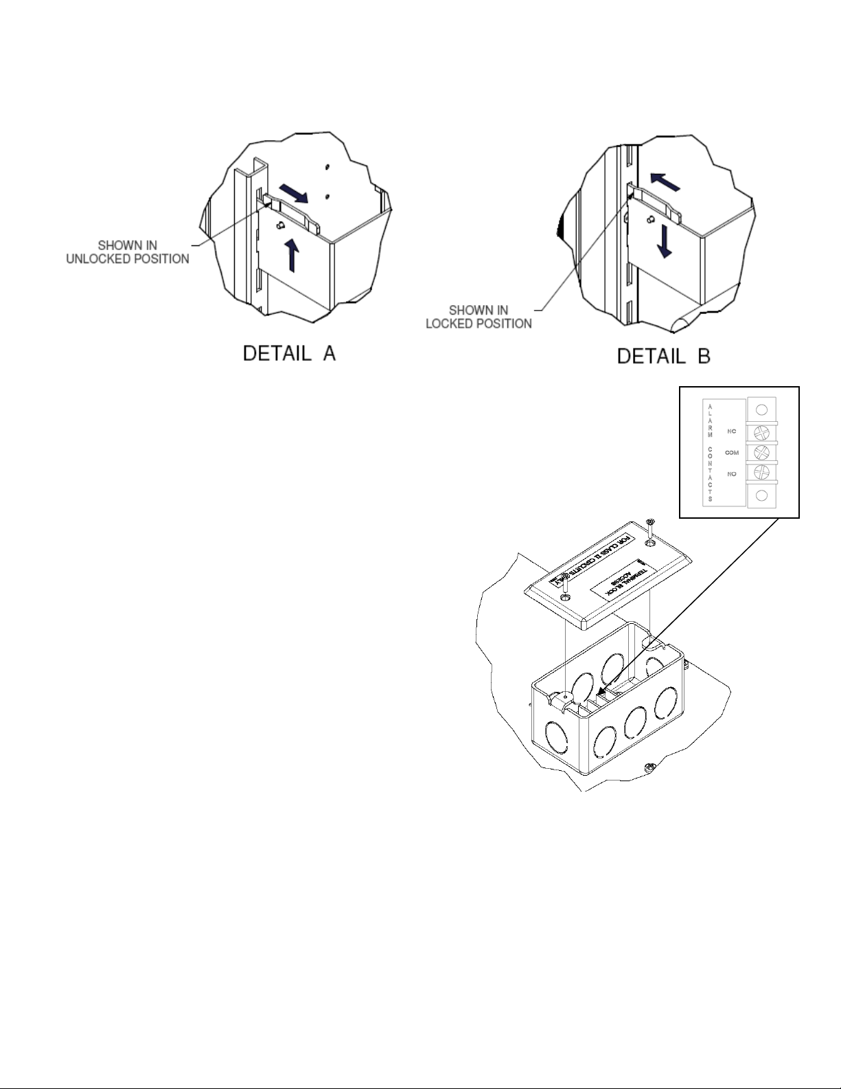
Shelving Installation – Shelving and Lighting comes installed for your desired light option. To
change shelf locations disengage lock as shown in Detail A, slide bracket up and remove. To install
insert shelf bracket tabs into pilaster and push down. Slide lock fully into hole.
Remote Alarms Contacts Access - The factory installed Remote alarm
contacts access box is located at the top of the cabinet behind the
microprocessor control.
1. Remove the cover to access the terminal connections.
2. Select and knock-out a hole to run field leads into electrical box
terminals.
3. The terminal block in the electrical box is
labeled for “normally open” and “normally
closed” activation. End user is
responsible for proper field installation.
Terminal connections are rated for class
II circuits only per NEC table 11(A).
(Limited power source less than 30vac 8
Amp. max, see applicable notes in NEC).
2-10 volt DC Output, is located at the top of the
control box behind the microprocessor control,
connect wires as per label (4-20 ma optional).
RS485 port - (Optional) terminal board for
RS485 port is located behind the cabinet façade, on the left hand side of the control box,
connect wires as per label.
Duplex/ or European Outlet - (Optional) is located near the top of the interior cabinet
back. This is a 15 amp 115 volt duplex PN 88010300 with its own power supply cord.
Duplex outlet power cord is wrapped up on the back of the cabinet top. Outlet is not interwired thru main cabinet supply and must be plugged into a 115 volt/ or 220/240V power
supply. Locate cabinet within 8 feet of the wall receptacle.
Access Port - (Optional) is provided with a spring loaded cover on the right hand side of
the cabinet.
- 4 -
Page 5

HUMIDITY INSTALLATION (if applicable)
The water supply should have a dedicated shutoff valve and regulator installed. Connect
the water supply to the humidifier (the operating pressure range is 10-60 psi). For best
results, provide a source of reverse osmosis water with a resistance of .05 to 1.0mΩ, which
will reduce the scale build up and cleaning frequency. Unit is equipped for water supply with
1/8” Male Pipe Threads. The humidifier reservoir water level may be adjusted by using the
adjusting thumb screw located on the float valve (see below).
The humidifier is a precision built instrument
that, given proper care, will provide years of
dependable service. Cleaning the humidifier
periodically is all that is required to insure
proper operation. Depending on local water
conditions, mineral solids and other matter
may accumulate in various parts of the unit.
These accumulations must be removed so
that water flows freely for efficient operation. Failure to clean the humidifier may result in
malfunction which will lead to repairs.
If higher humidity levels are unobtainable, loosen the
reducing coupling clamp and remove reducing coupling
boot and reducer PVC.
DRAIN INSTALLATION
The Chamber has a floor drain in the bottom of the
cabinet. A silicone drain stopper has been placed in this
drain. The drain stopper will prevent undesirable liquids from running into the drain. The
stopper can be removed if any possible liquids flowing into this drain are acceptable to go
to the floor drain.
An 18” length of 1/2" I.D. drain hose is shipped inside cabinet. Attach hose to drain stub
under cabinet with supplied clamp and run to an atmospheric floor drain. May substitute
longer drain hose as needed. Humidifier units will require a drain for overflow.
- 5 -
Page 6

ELECTRICAL
For electrical requirements see data information and wiring unit diagram located in parts
bag, inside of the cabinet.
Check the proposed external power outlet/supply to be used to ensure that the voltage,
phase and current carrying capacity of the circuit from the electrical panel correspond to the
requirements of the cabinet. NEVER use an extension cord to wire any unit. Refer to the
serial tag (nameplate data) for all pertinent electrical information.
Observe all Warning Labels. Disconnect power supply(s) to eliminate injury from
electrical shock or moving parts when servicing equipment.
GLYCERIN WELL ASSEMBLY
Important: For accurate product temperature reading, the
product-sensing bulb must be immersed in glycerin solution
contained in the provided well.
One glycerin well is furnished with each model. The
purpose of the glycerin is to simulate the product stored in
the Lighted Chamber. The glycerin temperature reflects the
product's temperature during normal operation.
Figure 1
After the unit is put into operation. Check to make sure that
the temperature indicating or alarm sensing bulb is
positioned inside the glycerin well. As far as possible
without touching the well itself.
OPERATION
The Lighted Chambers are designed for an operating range of 4°C to 44°C Temperature
only, 5°C to 44°C Temperature with Humidity and is intended for indoor use only.
These units employ a programmable controller to control the temperature, defrost and
humidity settings. The controller, which is located on the facade of the unit, is factory set.
Please see the separate instructions, part number 113635, on the operation of the
controller used in the Stability Chambers.
The cabinets use an evaporator coil, located on top of the cabinet as the heat-removing
source. Through the refrigeration process, heat is captured in the evaporator, transferred to
the condensing unit on top of the cabinet, and expelled to the surrounding outside air. It is
extremely important to allow a four-inch clearance on the top, rear, and sides of the unit for
the refrigeration process to function properly.
The cabinets utilize electrically operated heaters to warm the cabinets in the heating mode.
The heating elements are located in the interior cowl. The programmable control is factory
set with a cutout temperature to prevent the cabinet from exceeding its design limits.
- 6 -
Page 7

Note: The cabinets are equipped with two switches located on the façade. One is the main
power ON/OFF switch for the unit. The other is a three-position switch for the batterypowered alarm. The alarm switch is placed in the middle, or OFF position, for shipment.
When the Stability Chamber is put into operation, the top of the switch should be pushed in
to the ON position. With the switch in the ON position, the battery will sound the alarm if the
main power to the cabinet is interrupted. The switch flipped to the bottom position is used to
test the battery. This test must be done with power uninterrupted
will sound if the battery is good. This test should be done periodically. The battery is
located on the backside of the control box that is on top of the unit behind the façade.
to the cabinet. The alarm
MAINTENANCE
PERIODIC CLEANING
Disconnect power source, including optional duplex power cord if equipped, before
servicing or cleaning.
Beginning with the initial installation, the interior surfaces of the cabinet should be
periodically wiped down with a solution of warm water and baking soda. This solution will
remove any odors from spillage that has occurred. The exterior of the cabinet should also
be cleaned frequently with a commercial grade of glass cleaner. Caution: Do not use an
abrasive or alkaline solution.
Monthly cleaning of the condenser will aid the heat transfer characteristics of the
refrigeration system and increase its efficiency. Dust, dirt, and lint may accumulate on the
fins of the condensing unit. This obstruction may affect the flow of air through the
condenser, thereby lowering the efficiency of the system. A wire brush or a brush with stiff
bristles can be used to loosen these particles that are attached to the fins so that they may
be removed with a vacuum cleaner. Important: Failure to keep the condenser coil clean
and clear of obstructions could result in temperature loss and damage to the
compressor. All moving parts have been permanently lubricated and will generally require
no maintenance.
CLEANING THE HUMIDIFIER
Before Cleaning:
1. Disconnect the electrical plug from power source. Turn off water supply. (See Figure D)
2. Unfasten the Dome Strap and remove the Dome from the humidifier assembly by lifting it from
the chromed Motor Pan (Figure B).
- 7 -
Page 8

Figure C
Figure B
- 8 -
Figure D
Page 9

3. Lift out the Atomizing Unit that rests freely on the Reservoir.
4. Clean the Atomizing Unit. Do not submerge in water.
a. Slightly twist the Cylindrical Screen out of the lock position and remove.
b. Remove the Impeller Cap from the Pump Tube by tapping lightly against the bottom
edge of the Cap with a flat object, such as a knife or file. Do not tap the face of the
Impeller Cap.
c. Free the three Apertures in the pump bushing of accumulated solids (Figure C). To
do this, insert a pointed scraper or pipe cleaner through the open end of the Pump
Tube into the three Apertures on the side of the pump bushing. You may not
actually see the Apertures, but you can feel them. Gently poke and free the
Apertures of any solids that may have accumulated. Scrape out waste materials
along the inner walls of the Pump Tube.
d. Replace the Impeller Cap on the Pump Tube and lightly tap around the edge of the
Cap until it is in place. Do not tap the face of the Impeller Cap.
e. Spin the Pump Tube by hand to insure that it rotates freely.
f. Replace the Cylindrical Screen by twisting it into the lock position.
g. Brush the Vapor Maker Comb clean by using a small wire brush or an old
toothbrush. Also, clean out the Motor Pan.
5. Empty and clean the Reservoir of all liquids and waste materials. Care should be taken
so as not to disturb the Floats or Float Valve.
6. Reassemble the humidifier by placing the Atomizing Unit on the Reservoir and the
Dome on the chromed Motor Pan.
7. Re-install the humidifier into its bracket. For proper operation Atomizer must be
positioned as shown in Figure D.
Battery and Fuse replacement:
Battery for alarm is 9V lithium, and is located on rear of control box.
Fuse for control is a fast acting 1A 250V.
Only qualified service representatives should replace these items.
- 9 -
Page 10

Lamp replacement:
For your safety, turn off cabinet during re-lamping.
NOTE: Light output is dependent upon re-lamping with same type bulb.
TISSUE
PLANT GROWTH ARABIDOPSIS
4100K IN
50/50 MIX OF
5000K AND
6500K IN TIER
AND SIDE
LIGHTING
TIER
LIGHTING
50/50 MIX OF
5000K AND
6500K BULBS
IN SIDE
LIGHTING
CULTURE INCUBATOR GERMINATOR
4100K IN
4100K IN TIER
LIGHTING
50/50 MIX OF
5000K AND
6500K BULBS IN
SIDE LIGHTING
TIER
LIGHTING
50/50 MIX OF
5000K AND
6500K BULBS
IN SIDE
50/50 MIX OF
5000K AND
6500K BULBS
IN SIDE
LIGHTING
LIGHTING
T-8 5000K 24" T-8 4100K 24" T-8 4100K 24" T-8 4100K 24" T-8 5000K 48"
T-8 6500K 24" T-8 5000K 48" T-8 5000K 48" T-8 5000K 48" T-8 6500K 48"
T-8 5000K 48" T-8 6500K 48" T-8 6500K 48" T-8 6500K 48"
T-8 6500K 48"
Vertical lamp replacement, See detail A:
Loosen lamp sleeve by unscrewing both ends.
Once sleeve is able to slide up or down the lamp is then removable.
Replace lamp and retighten lamp sleeve.
Horizontal lamp replacement, See detail B:
Loosen (Do Not Remove) (4) side screws. This will allow the lamp cover to be
removed. Slide lamp cover down to expose bulbs. Give bulb a half turn to remove.
Replace bulb and lamp cover.
Horizontal lamp removal, See detail B: Lift the fixture up and fixture holder off of
the shelf bracket.
- 10 -
Page 11

MAINTENANCE SERVICE AND ANALYSIS GUIDE
MALFUNCTION POSSIBLE CAUSE SOLUTION
Compressor will not start - 1. Service cord unplugged 1. Plug in service cord
no hum 2. Fuse blown or removed 2. Replace fuse
3. Overload tripped 3. Determine reasons and correct
4. Control stuck open 4. Repair or replace
5. Wiring incorrect 5. Check wiring against the diagram
Compressor will not start - 1. Improperly wired 1. Check wiring against the diagram
hums but trips on overload 2. Low voltage to unit 2. Determine reason and correct
protector 3. Starting capacitor defective 3. Determine reason and replace
4. Relay failing to close 4. Determine reason, correct or replace
Compressor starts and runs, 1. Low voltage to unit 1. Determine reason and correct
but short cycles on overload 2. Overload defective 2. Check current, replace overload protector
protector 3. Excessive head pressure 3. Check ventilation or restriction in
refrigeration system
4. Compressor hot-return gas hot 4. Check refrigerant charge, fix leak if
necessary
Compressor operates long 1. Short of refrigerant 1. Fix leak, add refrigerant
or continuously 2. Control contact stuck 2. Repair or replace
3. Evaporator coil iced 3. Determine cause, defrost manually
4. Restriction in refrigeration 4. Determine location and remove restriction
system
5. Dirty condenser 5. Clean condenser
Compressor runs fine, but 1. Overload protector 1. Check wiring diagram
short cycles 2. Cold control 2. Differential too close - widen
3. Overcharge 3. Reduce charge
4. Air in system 4. Purge and recharge
5. Undercharge 5. Fix leak, add refrigerant
Starting capacitor open, 1. Relay contacts stuck 1. Clean contacts or replace relay
shorted or blown 2. Low voltage to unit 2. Determine reason and correct
3. Improper relay 3. Replace
Relay defective or burned out 1. Incorrect relay 1. Check and replace
2. Voltage too high or too low 2. Determine reason and correct
Refrigerated space too warm 1. Control setting too high 1. Reset control
2. Refrigerant overcharge 2. Purge refrigerant
3. Dirty condenser 3. Clean condenser
4. Evaporator coil iced 4. Determine reason and defrost
5. Not operating 5. Determine reason, replace if necessary
6. Air flow to condenser or 6. Remove obstruction for free air flow
evaporator blocked
Standard temperature system 1. Control setting is too low 1. Reset the control
freezes the product 2. Control points stuck 2. Replace the control
Objectionable noise 1. Fan blade hitting fan shroud 1. Reform or cut away small section of shroud
2. Tubing rattle 2. Locate and reform
3. Vibrating fan blade 3. Replace fan blade
4. Condenser fan motor rattles 4. Check motor bracket mounting, tighten
5. General vibration 5. Compressor suspension bolts not loosened
on applicable models - loosen them
6. Worn fan motor bearings 6. Replace fan motor
Failure to Heat 1. Manual overload tripped 1. Push reset on hi-limit switch
2. Incorrect setting 2. See control manual
3. Alarm enabled 3. See control manual
Humidity level not correct 1. Water supply interrupted 1. Check water supply
2. Clean Humidifier
2. Incorrect control settings 1. See control manual
3. Piping not connected / sealed 1. Connect tubing
4. No power to humidifier 1. Check power connections for humidifier
5. Unable to maintain higher humidity levels 1. Remove restriction on humidity output spout
6. Unable to maintain humidity tolerance. 1. Confirm humidity restrictor is properly
positioned in output spout
7. Humidity range too high or low 1. Modify humidity ON/OFF parameters
2. Modify dehumidification ON/OFF parameters
2. Seal joints
- 11 -
Page 12

TEMP PROBE
1254
- 12 -
 Loading...