

Noritz America RPK-EXT Installation Manual
Noritz Recirculation System (RPK-EXT) Installation Instructions
Page 1 of 5
Closely observe the following symbols warning used in this document, they are critical to your safety.
WARNING
CAUTION
WARNING
Prior to installation, examine the components carefully to make sure no damage has occured to the pump during shipment. Take
care to ensure the pump is not dropped or mishandled, dropping will damage the pump.
Before conducting any work, to prevent electrical shock, the power supply to the water heater and circulator should be disconnected.
Installation and service must be performed by a qualifed installer or service agency.
The safe operation of this pump requires that it be grounding in accordinace with the National Electrical code and local codes
or regulations.
If these safety instructions are not observed, it may result in personal injury.
If these safety instructions are not observed, it may result in malfunction or damage to the equipment.
Prior to installation, read these installation and operating instructions carefully. Installation
and operation must comply with local code regulations which may vary and take precedence
over these instructions.
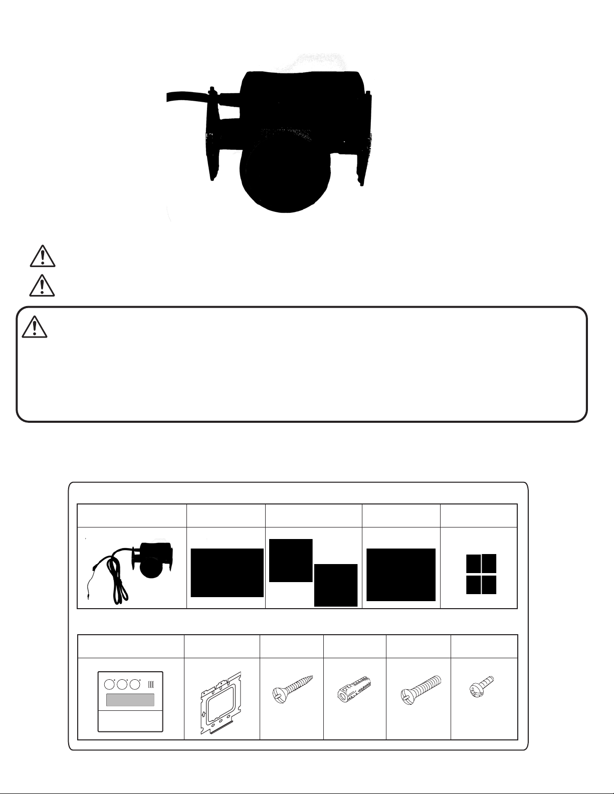
Included Parts
Visually inspect the contents of the package for any possible damage during shipment. Before starting installation, verify that
all included supply parts are present as shown.
Pump Parts
UPS15-55SFC 115V
(1)
3/4” Bronze
Flange
(2)
Gaskets
(2)
Bolts
(4)
Nuts
(4)
Controller Parts
RC-9018M Controller
(1)
Mounting
bracket
Raised countersunk
head wood screw
(1)
Wall anchor
(2)
Raised countersunk
head screw
(2)
(For junction box
installation)
(2)
Machine
screw
(2)
WARNINGWARNING
Circuit Board
Pump power connector
Connector
Ground Wire
Connector
Wiring Throughway
Page 2 of 5
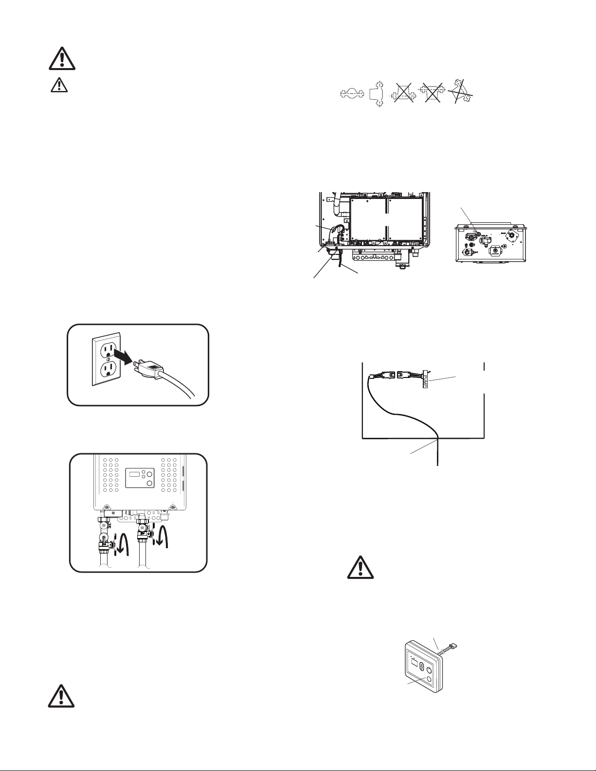
DO NOT install this pump outdoors.
DO NOT start the pump until
the system has been filled.
Pump is suitable for indoor applications only
When making pipe connections, be sure to
follow the pipe manufacturer's recommendations
and all code requirements for piping material.
Arrows on the side or bottom of the pump
housing indicate direction of flow through the
pump. The circulator pumps can be
installed in both vertical and horizontal lines.
The pump must be installed with the motor shaft
positioned horizontally.
Under no circumstances should the pump be
installed with the shaft vertical or where the
shaft falls below the horizontal plane.
We recommend that isolating valves be installed
on each side of the pump. If possible, do not
install elbows, branch tees, and similar fittings
just before or after the pump. Provide support to
the pump or adjacent plumbing to reduce
thermal and mechanical stress on the pump.
Pump Installation
6. Pump should be mounted such that the arrow at the
bottom of the pump is pointing towards the heater. Pump
must be mounted with the motor in a horizontal position.
Acceptable
Acceptable pump mounting positions
Not acceptable
7. The pump comes pre-assembled with a wiring harness
to be easily connected into the water heater. Feed wiring through
the wiring throughway located at the bottom of the water heater.
Wiring Throughway
PUMP
1. Turn the remote controller off (if installed). Disconnect
electric power to the water heater.
2. Shut off the incoming water and gas valves to the
water heater.
Front View Bottom View
8. Locate Connector marked “PUMP” and insert pump power
connector. Note: A dummy plug is inserted from the factory. This
connector must be removed before connecting the pump power
connector. Press lightly on the connector to release the dummy plug.
Pump Control
Wire Tag
Wiring
Throughway
9. Connect the ground wire (green color wire) to the screw at the
base of the water heater.
10. Replace the front cover.
11. Turn back on the water and gas valves. Ensure the system
is fully filled and leak checked. Pump should be flooded with water
before it is started.
Do not start the pump until the system
has been filled.
3. Remove the front cover of the water heater.
4. Thouroughly clean and flush lines prior to pump
installation.
5. Install pump in accordance with the typical pluming
application illustrated on the following page.
DO NOT install pump at the lowest point of the
system where it can collect dirt and sediment.
12. Disconnect the remote controller RC-7651M. Re-connect the
remote controller RC-9018M (included).
Note: For models NR83DVC and NR98DVC remote is installed in
the front cover. Do not physically remove the RC-7651M remote
from the unit.
Remote Controller
Connecting Wire
13. Reconnect electrical power to the water heater and turn on the
remote controller.
 Loading...