

Noritz America EZ98DV, EZ111DV Installation Manual
CONDENSING TANKLESS GAS WATER HEATER
Installation Manual
Models : EZ111DV (GQ-C3260WX-FF US)
EZ98DV (GQ-C2860WX-FF US)
WARNING
If the information in these instructions is not
followed exactly, a fire or explosion may result
causing property damage, personal injury or
death.
• Do not store or use gasoline or other
flammable vapors and liquids in the vicinity of
this or any other appliance.
• WHAT TO DO IF YOU SMELL GAS
- Do not try to light any appliance.
- Do not touch any electrical switch; do not use
any phone in your building.
- Immediately call your gas supplier from a
neighbor’s phone. Follow the gas supplier’s
instructions.
- If you cannot reach your gas supplier, call the
fire department.
• Installation and service must be performed by
a qualified installer, service agency or the gas
supplier.
FOR USE IN RESIDENTIAL OR MANUFACTURED HOME APPLICATIONS.
Installation must conform with local codes, or in the absence of local codes, the National Fuel Gas Code, ANSI Z223.1 / NFPA
54 - latest edition and/or the Natural Gas and Propane Installation Code CSA B149.1 - latest edition.
When applicable, installation must conform with the Manufactured Home Construction and Safety Standard, Title 24 CFR,
Part 3280 or the Canadian Standard CAN/CSA-Z240 MH Mobile Homes, Series M86.
Noritz America reserves the right to discontinue, or change at any time, the designs and/or specifications of its products
without notice.
CAUTION
Requests to Installers
• In order to use the Water Heater safely, read
this installation manual carefully, and follow the
installation instructions.
•
Failures and damage caused by erroneous work
or work not as instructed in this manual are not
covered by the Noritz America Limited Warranty.
• Check that the installation was done properly in
accordance with this Installation Manual upon
completion.
• After completing installation, either place this
Installation Manual in a plastic pouch and attach
it to the side of the Water Heater (or the inside
of the pipe cover or recess box if applicable),
or hand it to the customer to retain for future
reference. Also, be sure to fill in all of the
required items on the warranty and to hand
the warranty to the customer along with the
Owner’s Guide.
Contact Noritz America at 1-866-766-7489, if you have any questions or concerns.
NORITZ America Corporation
SBB8164
Rev. 05/19
Low NOx Approved by SCAQMD
14 ng/J or 20 ppm
(Natural Gas Only)

Contents
1 Before Installation 3
2 About the Water Heater 5
2.1 Included Accessories ....................... 5
2.2 Optional Accessories ....................... 5
2.3 Specifications ................................... 7
2.4 Dimensions ...................................... 8
2.5 External View ................................... 10
3 Choosing an Installation Location 11
4 Installation Clearances 13
4.1 Indoor Installation ........................... 13
4.2 Outdoor Installation ........................ 14
4.3 For Quick Connect Multi-System ..... 14
5 Installation of the Water Heater 15
8 Connecting the Water Supply 41
8.1 Installation ....................................... 41
8.2 Water treatment .............................. 43
9 Connecting the Condensate Drain 45
10 Connecting Electricity 47
10.1 Water Heater ................................... 47
10.2 Remote Controller ........................... 47
10.3 Recirculation Pump .......................... 48
10.4 Quick Connect Cord-2 ..................... 49
11
Installation of the Remote Controller
11.1 General Requirements ..................... 50
11.2 RC-7651M-A .................................... 50
11.3 RC-9018M ........................................ 52
50
5.1 Mounting the Water Heater
to the wall ........................................ 15
5.2 Elevation Adjustment Above
2,000 ft ............................................. 16
5.3 Filling the condensate container
with water ........................................ 16
6 Venting the Water Heater 17
6.1 Venting Installation Sequence ......... 17
6.2 General Requirements ..................... 17
6.3 Select a Vent Type ............................ 23
6.4 Vent Pipe Installation
6.5 Vent Pipe Installation
(Non-Direct Vent) ............................ 30
6.6 Outdoor Installation ........................ 36
7 Connecting the Gas Supply 37
(Direct Vent)
.. 24
12 Setting the DIP Switches 56
13 Trial Operation 57
14 Checklist After Installation 59
15 Plumbing Applications 61
16 Installation of the Quick Connect
Multi-System 63
17 Maintenance 64
17.1 Periodic Check ................................. 64
17.2 Procedure for Flushing the Heat
Exchanger ........................................ 65
2
Contents
1 Before Installation
Potential dangers from accidents during installation and use are divided into the following four categories.
Closely observe these warnings, they are critical to your safety.
DANGER
WARNING
CAUTION
NOTICE
DANGER
Checkup
Check the fixing brackets and vent pipe yearly for damage or wear. Replace if necessary.
WARNING
Precautions on Vent Pipe Replacement
The vent system will almost certainly need to be
replaced when this appliance is being installed.
Only use vent materials that are specified in this
Installation Manual for use on this appliance.
Refer to the “Venting the Water Heater” section
for details. If PVC, CPVC, or Category IV listed pipe
is already installed, check for punctures, cracks,
or blockages and consult with the vent pipe
manufacturer before reusing.
If the flexible PP pipe is already installed, replace to
the new flexible PP pipe.
Improper venting may result in fires, property
damage or exposure to Carbon Monoxide.
Snow Precaution
If this product will be installed in an area where
snow is known to accumulate, protect the vent
termination from blockage by snow drifts or
damage from snow falling off of roofs.
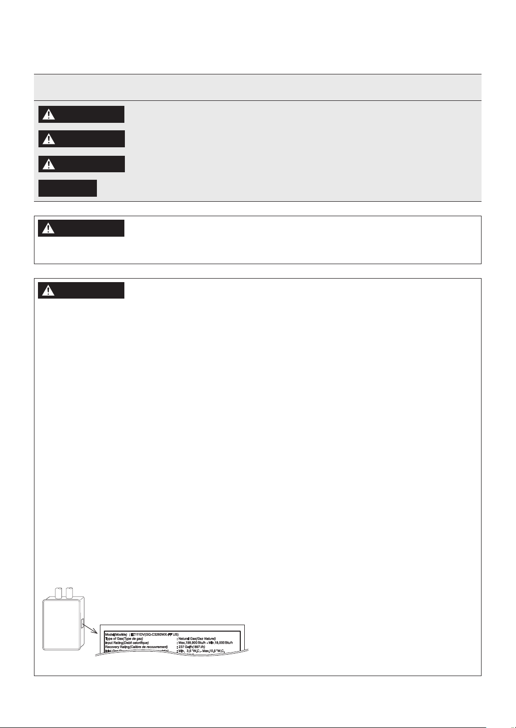
Check the Gas
• Check that the rating plate indicates the correct
type of gas.
• Check that the gas supply line is sized for
199,900 Btu/h or 180,000 Btu/h.
199,900 Btu/h: EZ111DV (GQ-C3260WX-FF US)
180,000 Btu/h: EZ98DV (GQ-C2860WX-FF US)
Indicates an imminently hazardous situation which, if not avoided, will result in death
or serious injury.
Indicates a potentially hazardous situation which, if not avoided, could result in death
or serious injury.
Indicates a potentially hazardous situation which, if not avoided, may result in minor or
moderate injury.
Indicates a potentially hazardous situation which, if not avoided, may result in property
damage.
Check the Power
The power supply required is 120 VAC, at 60 Hz.
Using the incorrect voltage may result in fire or
electric shock.
Use Extreme Caution if Using With a Solar PreHeater
Using this appliance with a solar pre-heater can
lead to unpredictable output temperatures and
possibly scalding. If absolutely necessary, use
mixing valves to ensure output temperatures do
not get to scalding levels.
Do not use a solar pre-heater with the Quick
Connect Multi-System because the system may not
operate properly.
Precautions for Mobile Home Installation
• Verify that the gas supply type matches the gas
type listed on the rating plate. If a gas conversion
must be done, follow the instructions listed in
the gas conversion kit manual.
• If this product will be installed indoors, usage
of the SV conversion kit (SV-CK-2) and the Flex
Vent 2 in. Conversion Kit (EZ2-CK) are prohibited.
Make sure to follow all clearance and venting
requirements outlined in this manual.
Chemicals
This product can expose you to chemicals including
lead, lead compounds and carbon bisulfide which
are known to the State of California to cause
e.g. EZ111DV (GQ-C3260WX-FF US)
cancer, birth defects or other reproductive harm.
For more information go to
www.P65Warnings.ca.gov.
Before Installation
3
CAUTION
Do Not Use Appliance for Purposes Other Than
Those Specified
Do not use for other than increasing the
temperature of the water supply, as unexpected
accidents may occur as a result.
Check Water Supply Quality
If the water supply is in excess of 12 grains
per gallon (200 mg/L) of hardness, acidic or
otherwise impure, treat the water with approved
methods in order to ensure full warranty
coverage.
NOTICE
• This appliance is suitable for combination
potable water and space heating applications.
It cannot be used for space heating
applications only.
• Do not use this appliance if any part has been
underwater. Immediately call a qualified
service technician to inspect the appliance
and replace any part of the control system
and gas control which has been under water.
4
Before Installation
2 About the Water Heater
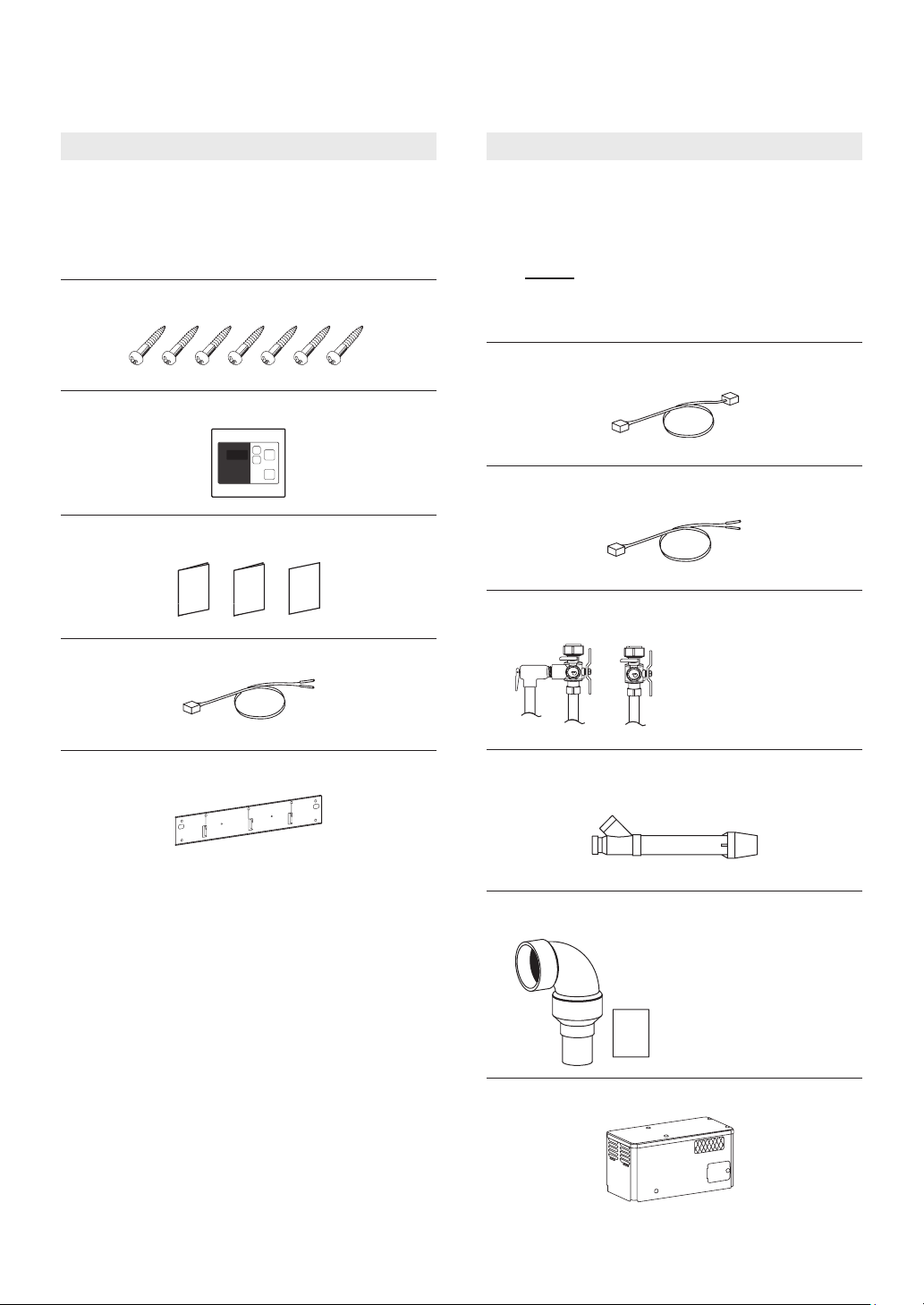
2.1 Included Accessories 2.2 Optional Accessories
The following accessories are included with the
Water Heater.
Check for any missing items before starting
installation.
Anchoring Screw (× 7)
Remote Controller (× 1)
[RC-7651M-A]
Owner’s Guide, Warranty card,
Installation Manual (this document) (1 each)
Remote Controller Cord (6 ft (1.8 m)) (× 1)
(See page 50)
The accessories listed below are not included
with the Water Heater, but may be necessary for
installation.
NOTE
Quick Connect Cord (× 1)
[QC-2]
Remote Controller Cord (26 ft (7.9 m)) (× 1)
[RC-CORD26]
Isolation Valves (1 each)
(includes pressure relief valve)
Additional vent pieces are available;
consult the latest product catalogue
for details.
Isolation valves are
necessary for flushing the
Heat Exchanger.
They allow for easy flushing
and troubleshooting of the
system.
Wall Mounting Bracket (× 1)
PVC Concentric Termination (× 1)
2 in. (50 mm) : [PVC-2CT]
3 in. (75 mm) : [PVC-3CT]
2 in. SV Conversion Kit (× 1)
[SV-CK-2]
• 90° Elbow
(With Inlet Screen)
• 2 in. × 3 in. Increaser
coupling
• 2 in. Pipe
• Installation Manual
(Check List)
Outdoor Vent Cap (× 1)
[VC-6]
About the Water Heater
5
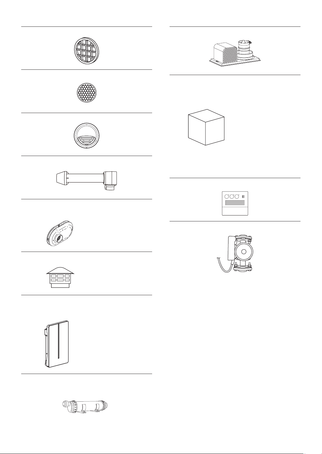
Bird Screen for 2 in. (50 mm) PVC
[VT2-PVCS]
Flex Vent 2 in. Conversion Kit
[EZ2-CK]
Bird Screen for 3 in. (75 mm) PVC
[VT3-PVCS]
3 in. (75 mm) Horizontal Hood Termination
[PVT-HL]
Universal Concentric Vent Kit
[PVC-UCVK]
Low Profile Termination Kit
2 in.: [PVC-2LPT]
3 in.: [PVC-3LPT]
ULC S636 / UL 1738
certified for use in both
Canada and USA
Flex Vent 2 in. Kit – 25 ft
[EZ2FVK-1]
Flex Vent 2 in. Kit – 35 ft
[EZ2FVP35-3]
Remote Controller (× 1)
[RC-9018M]
Noritz Recirculation System
[RPK-EXT]
During the installation of
Flex Vent 2 in. Kit (EZ2FVK-1
and EZ2FVP35-3), ambient
temperatures must be
greater than 40°F (5°C).
Afterwards, installation
site ambient temperature
must be greater than -4°F
(-20°C). Flex vent pipe
breakage may occur if these
temperature requirements
are not observed.
(See page 52)
Plastic Rain Cap
[PRC-1]
Not approved for use in
Canada.
Noritz Connect Wireless Adapter
NWC-ADAPTER (× 1)
[NAW-1 US]
Noritz Connect Wireless
Adapter enables users to:
• Remote control (Power
ON/OFF, Adjust set
temperature)
For more information, visit
the Noritz America website
(http://wifi.noritz.com/).
Neutralizer (× 1)
[NC-1S]
(For 1 Water Heater)
6
About the Water Heater
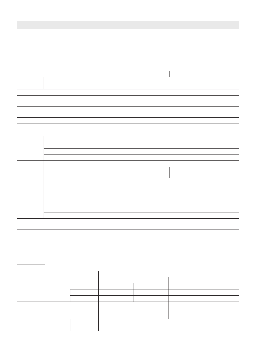
2.3 Specifications
• Specifications may be changed without prior notice.
• The capacity may differ slightly, depending on the water pressure, water supply, piping conditions, and water
temperature.
Item Specification
Model Name EZ111DV (GQ-C3260WX-FF US) EZ98DV (GQ-C2860WX-FF US)
Type
Ignition Direct Ignition
Operating Pressure
Minimum Activation Flow Rate*
Minimum Operating Flow Rate*
Dimensions (Height) × (Width) × (Depth) 27.0 in. (687 mm) × 18.5 in. (471 mm) × 14.1 in. (359 mm)
Weight 70 lbs. (32 kg)
Water Holding Capacity 0.83 Gallon (3.1 L)
Connection
Sizes
Power
Supply
Materials
Safety Devices
Included Accessories
* Minimum flow rate may change by setting temperature and water temperature.
Installation Indoor / Outdoor Wall mounted
Air Supply / Exhaust Power Vented
15-150 psi
(Recommended 50 to 80 psi for maximum performance)
0.5 GPM (2.0 L/min)
0.29 GPM (1.1 L/min)
Water Inlet NPT 3/4 in.
Hot Water Outlet NPT 3/4 in.
Gas Inlet NPT 3/4 in.
Condensate Drain NPT 1/2 in.
Supply 120 VAC (60 Hz)
Consumption
Maximum Current 4 Amps
Casing
Flue Collar PP
Primary Heat Exchanger Stainless Steel Sheeting, Stainless Steel Tubing
Secondary Heat Exchanger Stainless Steel Sheeting, Stainless Steel Tubing
NG: 96 W LP: 80 W
Freeze Prevention: 114 W
• Front Cover: Hot-dipped zinc-aluminum-magnesium-alloy-coated
steel w/ Polyester Coating
• Casing: Zincified Steel Plate / Polyester Coating
Flame Rod, High Limit Switch, Lightning Protection Device (ZNR),
Freezing Prevention Device, Fan Rotation Detector
Remote Controller, Remote Controller Cord, Anchoring Screws, Wall
Mounting Bracket
NG: 75 W LP: 64 W
Freeze Prevention: 114 W
Performances
Item
Gas Consumption NG 199,900 Btu/h 18,000 Btu/h 180,000 Btu/h 18,000 Btu/h
LP 199,900 Btu/h 18,000 Btu/h 180,000 Btu/h 18,000 Btu/h
Maximum Hot Water Capacity
(45°F (25°C) Rise)
Capacity Range 0.5-11.1 GPM (2-42 L/min) 0.5-9.8 GPM (2-37 L/min)
Temperature Settings
°F Mode 100-140°F (In 5°F intervals) (9 Options)
°C Mode 37-48°C (In 1°C intervals), 50-60°C (In 5°C intervals) (15 Options)
EZ111DV (GQ-C3260WX-FF US) EZ98DV (GQ-C2860WX-FF US)
Maximum Minimum Maximum Minimum
8.7 GPM (33 L/min) 7.6 GPM (29 L/min)
Performance
About the Water Heater
7

2.4 Dimensions
2.3”[58]
27.1”[690]
HOT WATER OUTLET(3/4”)
WATER DRAIN VALVE
7×Φ0.2”[Φ6]
2.0”[52]
4×0.24”×0.6”[6×15]OBLONG HOLE
2×0.4”×0.24”[10×6]OBLONG HOLE
16.0”[406]
10.2”[260]
5.1”[130]
7.2”[183]
2.1”[5.3]
4×Φ0.5”[Φ13]
WALL MOUTING BRACKET
(INCLUDED ACCESSORY)
3×0.5”[12]×1.6”[40]RECTANGLE HOLE
10.2”[260]
0.5”[12]
27.4”[696]
1.6”[40]
2.2”[56]
3.9”[100]
5.2”[132]
6.7”[169]
8.1”[206]
0.3”[8] 14.1”[359]
1.1”[27]
2.3”[59]
26.0”[661]
3.5”[89]
0.4”[10]
25.9”[658]
8
About the Water Heater
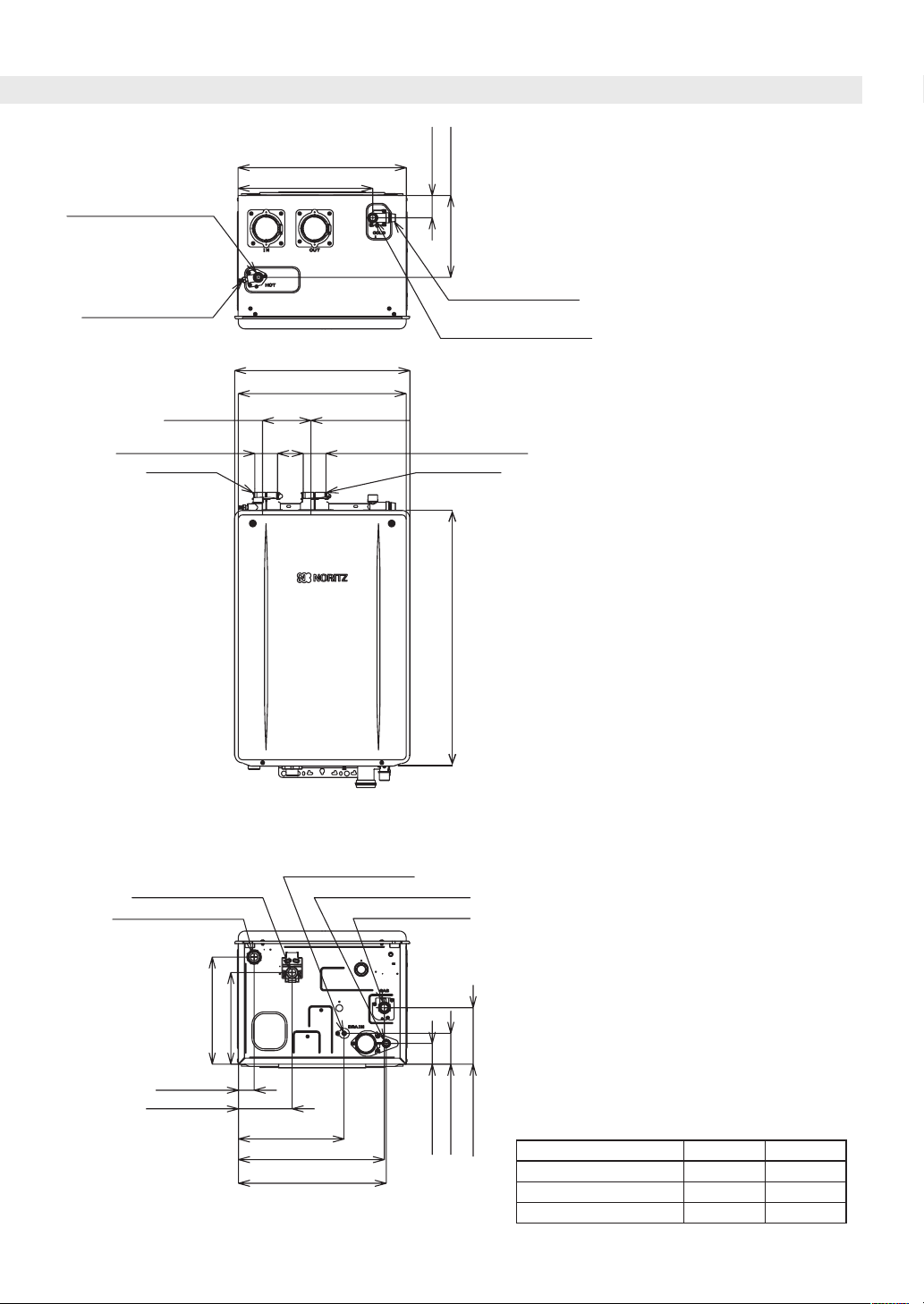
HOT WATER OUTLET(3/4”)
17.8”[452]
14.2”[362]
2.4”[60]
8.7”[220]
<inch [mm]>
WATER DRAIN VALVE
AIR INLET FLUE COLLAR
WATER DRAIN VALVE
(WATER FILTER)
COLD WATER INLET(3/4”)
18.5”[471]
17.8”[451]
10.5”[266]5.1”[130]
I.DΦ2.4”[Φ61]I.DΦ2.4”[Φ61]
27.0”[687]
WIRING THROUGHWAY
WIRING THROUGHWAY
(AC120V)
11.3”[288]
1.7”[42]
5.7”[144]
(VIEW FROM BOTTOM)
WATER DRAIN VALVE
CONDENSATE DRAIN(1/2”)
9.7”[246]
11.2”[284]
15.4”[392]
15.6”[397]
GAS INLET(3/4”)
2.2”[56]
3.3”[83]
HEIGHT OF EACH FITTING FROM CASE
6.0”[152]
HOT WATER OUTLET TOP 1.9”[49]
COLD WATER INLET TOP 2.1”[53]
CONDENSATE DRAIN BOTTOM 1.7”[42]
GAS INLET BOTTOM 2.2”[56]
About the Water Heater
9
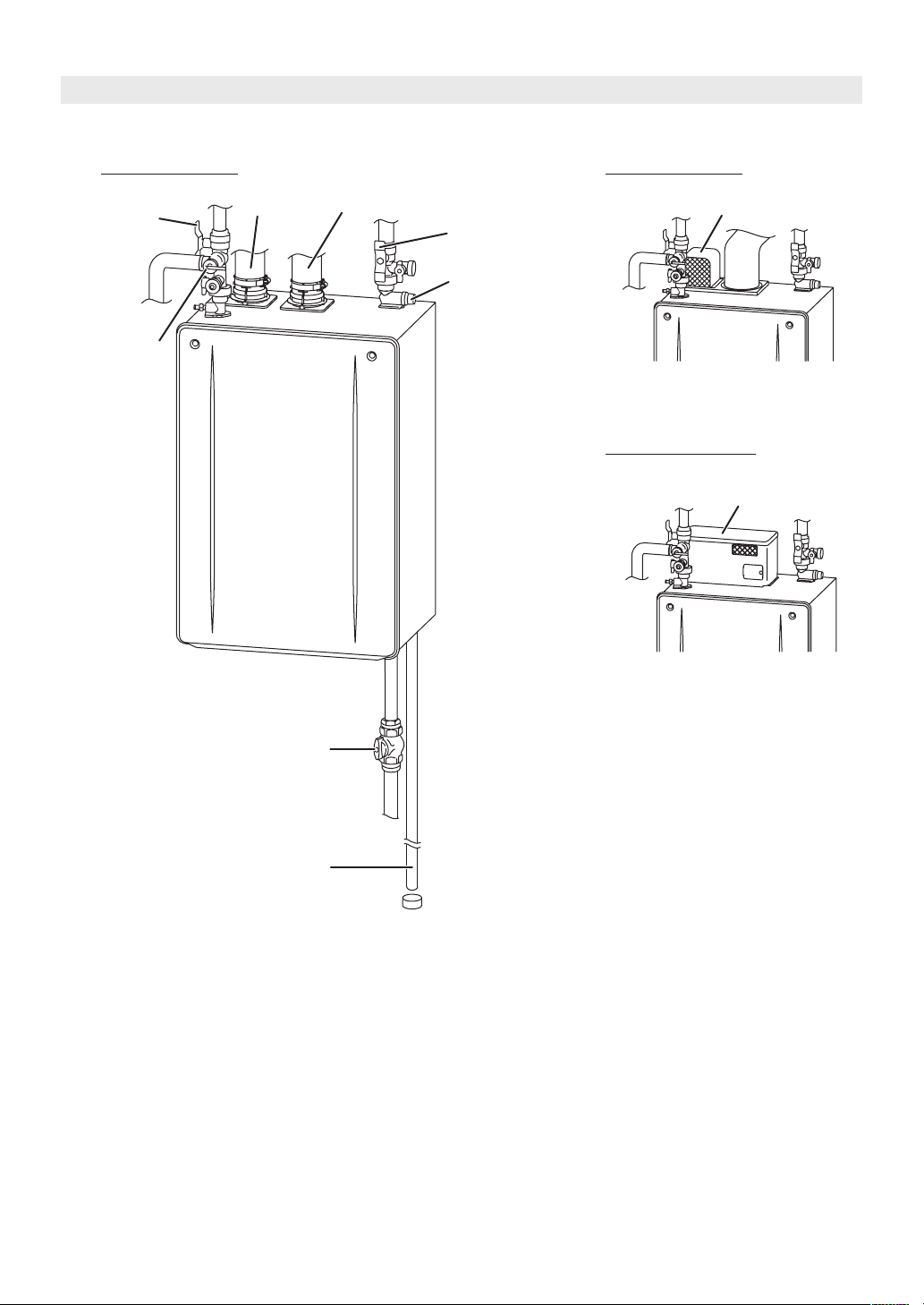
2.5 External View
Indoor Installation Indoor Installation
Hot Water
Valve
Pressure Relief
Valve
Intake Pipe Exhaust Pipe
Flex Vent 2 in. Conversion Kit
Water Supply Valve
Water Drain Valve
(with Water Filter)
Outdoor Installation
Outdoor Vent Cap
10
About the Water Heater
Gas Supply Valve
Condensate Drain Pipe
3 Choosing an Installation Location
DANGER
Locate the vent terminal and make sure there
are no obstacles around the termination for
exhaust to accumulate or be obstructed.
Do not enclose the termination with corrugated
metal or other materials.
Carbon monoxide poisoning or fire may occur
as a result.
WARNING
• Avoid places where fires are common,
such as those where gasoline, benzene and
adhesives are handled, or places in which
corrosive gases (ammonia, chlorine, sulfur,
ethylene compounds, acids) are present.
If you do not follow the above, a fire or
explosion may result causing property
damage, personal injury or death.
• Avoid installation in places where dust or
debris will accumulate.
Dust may accumulate and reduce the
performance of the fan of the appliance.
This can result in incomplete combustion.
• Avoid installation in places where special
chemical agents (e.g. hair spray or spray
detergent) are used.
Ignition failures and malfunctions may occur
as a result.
• Do not install this Water Heater in a
recreational vehicle or on a boat as this may
be a Carbon Monoxide Poisoning Hazard.
• The manufacturer does not recommend
installing the Water Heater in an attic due to
safety issues.
If you install the Water Heater in an attic:
- Make sure the appliance will have enough
combustion air and proper ventilation.
- Keep the area around the Water Heater
clean. Dust may accumulate and reduce the
performance of the fan of the appliance.
This can result in incomplete combustion.
- A drain pan, or other means of protection
against water damage, is required to be
installed under the Water Heater in case of
leaks.
CAUTION
Do not install in the following places
• A location where it is not free from obstacles
and stagnant air.
• Near staircases or emergency exits.
• A place where it may be threatened by falling
objects, such as under shelves.
• On common walls as the appliance will make
some operational noises while it is running.
Consideration to the surroundings
• Do not install the Water Heater where the
exhaust will blow on outer walls, other
walls or material not resistant to heat. Also
consider the surrounding trees and animals.
The heat and moisture from the Water
Heater may cause discoloration of walls and
resinous materials, or corrosion of aluminum
materials.
• Do not locate the vent termination directed
towards a window or any other structure
which has glass or wired glass facing the
termination.
• Take care that noise and exhaust gas will not
affect neighbors.
• If the appliance is installed in a location with
very high humidity, condensate may form
inside the appliance and/or cause incomplete
combustion, damage to the electrical
components, or electric leakage.
Install according to regulations and manual
• Install the Water Heater in an area that allows
for the proper clearances to combustible
and non-combustible construction. Consult
the rating plate on the appliance for proper
clearances.
• The Water Heater must be installed according
to manual.
• Before installing, make sure that the exhaust
flue termination will have the proper
clearances according to the National Fuel
Gas Code (ANSI Z223.1 - latest edition) or the
Natural Gas and Propane Installation Code
(CSA B149.1).
Choosing an Installation Location
11
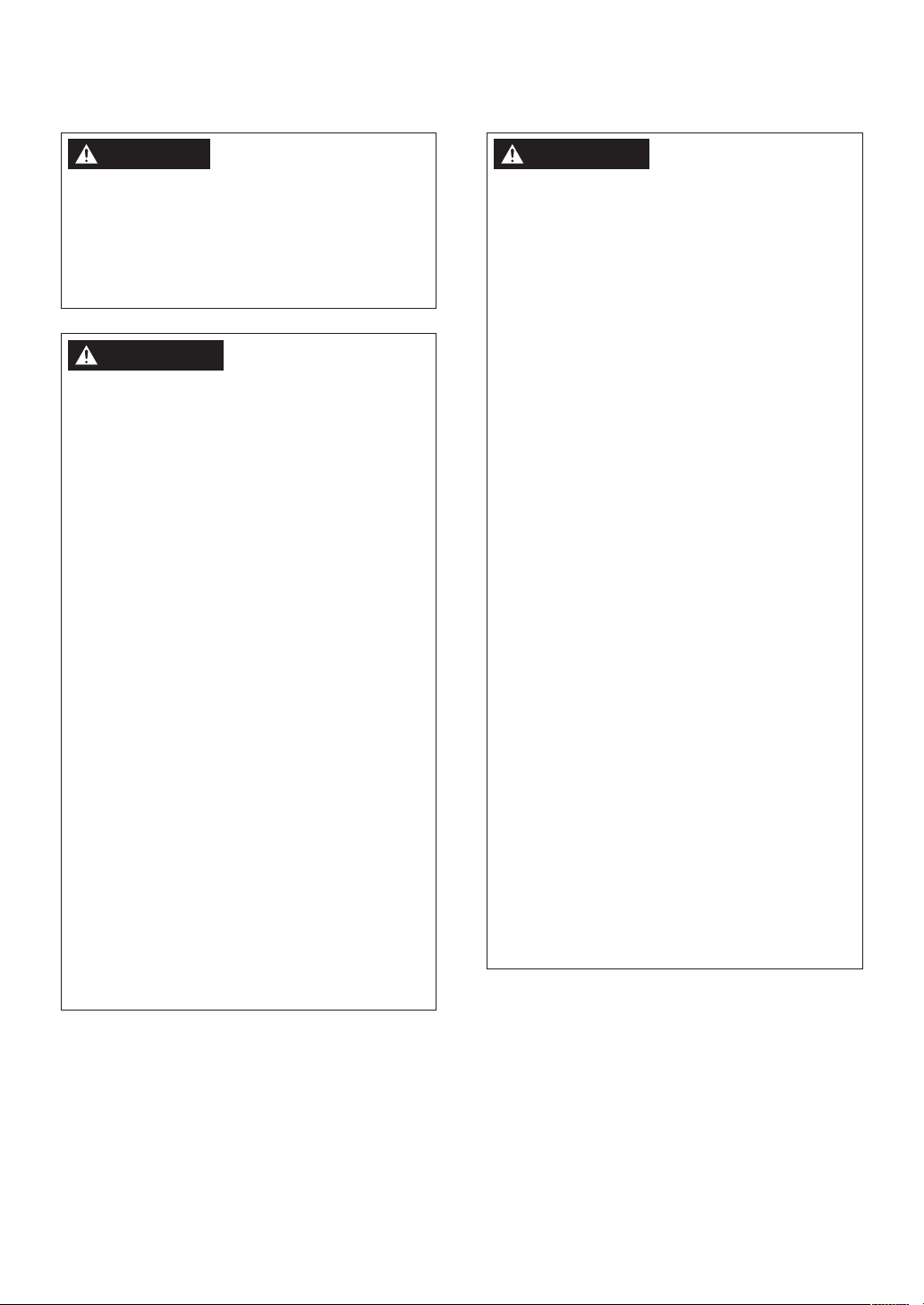
CAUTION
NOT
CORRECT
NOT
Installation in the vicinity of gas ranges,
stoves, fans, and range hoods
• Avoid installation above gas ranges or stoves.
• Avoid installation between the kitchen fan
and stove. If oily fumes or a large amount of
steam are present in the installation location,
take measures to prevent the fumes and
steam from entering in the appliance.
CORRECT
• Install in a location where the exhaust gas
flow will not be affected by fans or range
hoods.
CORRECT
NOTICE
• Place the appliance for easy access for
maintenance and repair.
• Do not install the Water Heater in a location
where the appliance will be exposed to
excessive winds.
• Locate the appliance in an area where
leakage from the appliance or connections
will not result in damage to the area adjacent
to the appliance or to the lower floors of the
structure. When such installation locations
cannot be avoided, a suitable drain pan,
adequately drained, must be installed under
the appliance. The pan must not restrict
combustion air flow.
• As with any water heating appliance, the
potential for leakage at some time in the life
of the product does exist. The manufacturer
will not be responsible for any water damage
that may occur.
• Water quality:
If this Water Heater will be installed in a
location where the hardness of the supply
water is high, scale Build-up may cause
damage to the Heat Exchanger.
Perform suggested treatment and
maintenance measures in reference to “8.2
Water Treatment”.
Damage to the Water Heater as a result
of the below is not covered by the Noritz
America Limited Warranty.
- Water in excess of 12 gpg (200 mg/L) of
hardness
- Poor water quality (see the following table)
Contaminant Maximum Allowable Level
Total Hardness* 200 mg/L (12 gpg) or less
Aluminum 0.05 to 0.2 mg/L or less
Chloride 250 mg/L or less
Copper 1.0 mg/L or less
Iron 0.3 mg/L or less
Manganese 0.05 mg/L or less
pH 6.5-8.5
Total Dissolved Solids 500 mg/L or less
Zinc 5 mg/L or less
Sulfate 250 mg/L or less
Residual chlorine* 4 mg/L or less
Source: EPA National Secondary Drinking Water
Regulations (40 CFR Part 143.3)
* Maximum limit suggested by Noritz.
12
Choosing an Installation Location
NOTE
Consult with the customer concerning
the location of installation.
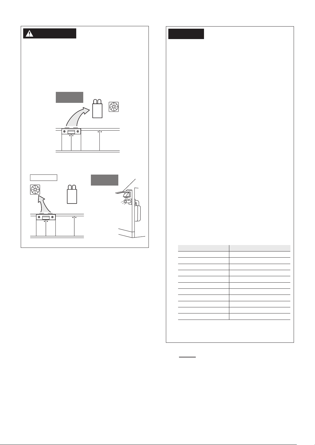
State of California: The Water Heater must be
12 in. (300 mm)
or mor
or more
** 8 in. (203 mm) or more
braced, anchored or strapped to avoid moving
during an earthquake. Contact local utilities for code
requirements in your area or call 1-866-766-7489
and request instructions.
4 Installation
Clearances
The Commonwealth of Massachusetts:
1) This Water Heater can only be used in outdoor
applications if the usage is restricted to
summertime usage exclusively.
2) The Water Heater can be used for hot water only
and not in a combination of domestic and space
heating.
For Venting Manufacturers Requirements, see the
Noritz America website (www.noritz.com).
WARNING
Before installing, check for the following:
Install in accordance with relevant building and
mechanical codes, as well as any local, state or
national regulations, or in the absence of local
and state codes, refer to National Fuel Gas Code
ANSI Z223.1 / NFPA 54 - latest edition. In Canada,
see the Natural Gas and Propane Installation
Code CSA B149.1 - latest edition for detailed
requirements.
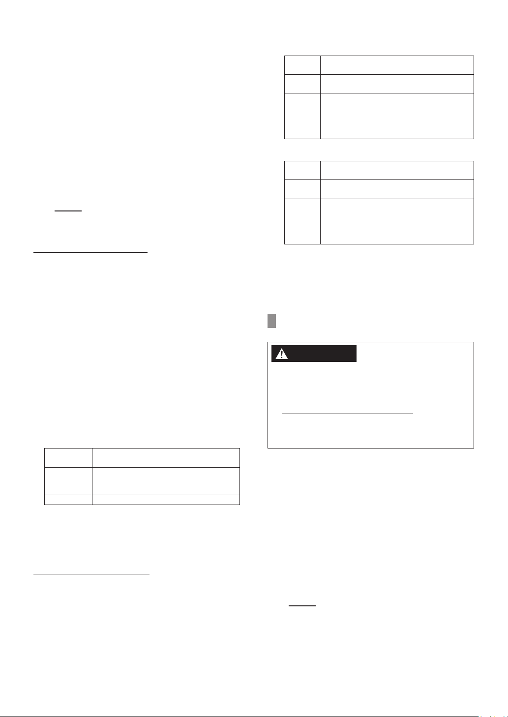
4.1 Indoor Installation
Required Clearances From the Water Heater
Maintain the clearances from both combustible and
non-combustible materials.
e
4 in. (100 mm)
or more
3 in. (76 mm)
Securing of space for inspection/repair
In order to facilitate inspection and repair, the
minimum clearances should be met.
*
Exhaust
*
** **
24 in.
(610 mm)
or more
* 3 in. (76 mm) or more
Choosing an Installation Location / Installation Clearances
13

Cooking Equipment
The dividing pla
be of non-combus
material of a width
gr
Heate
the bottom edge of
(76-457 mm)
Surrounding the area of installation
When utilizing an indoor air supply, if the Water
Heater will be installed in the vicinity of a
permanent kitchen range or stove that has the
possibility of generating steam that contains fats
or oils, use a dividing plate or other measure to
ensure that the Water Heater is not exposed to air
containing such impurities.
Exhaust hood
te should
tible
eater than the Water
r.
Range
4.2 Outdoor Installation
Required Clearances From the Water Heater
Maintain the clearances from both combustible and
non-combustible materials.
[
When installing the Water Heater in a common side
corridor
]
the exhaust port
84 in. (2,134 mm)
or more
47 in. (1,194 mm)
or more
Handrail
Common side
corridor
4.3 For Quick Connect Multi-System
The Quick Connect Cord is 6 ft (1.8 m) long.
Install the Water Heaters 3-18 in. (76-457 mm)
apart from each
to reach between the Water Heaters.
other to ensure the cord will be able
3 in. (76 mm) or more
24 in. (610 mm)
or more
3-18 in.
36 in. (910 mm)
or more
Outdoor Vent Cap
(VC-6)
14
Installation Clearances
5 Installation of the Water Heater
IN OUT
Anchoring
Screw
Intake
5.1 Mounting the Water Heater to the
wall
WARNING
Do not drop or apply unnecessary force to the
appliance when installing. Internal parts may be
damaged and may become highly dangerous.
CAUTION
• Protect your hands with gloves and take
caution to not inflict injury.
• Be careful not to hit electrical wiring, gas, or
water piping while drilling holes.
NOTICE
• The weight of the appliance will be applied
to the wall. If the strength of the wall is not
sufficient, reinforcement must be done to
prevent the transfer of vibration.
• Install the appliance on a vertical wall and
ensure that it is level.
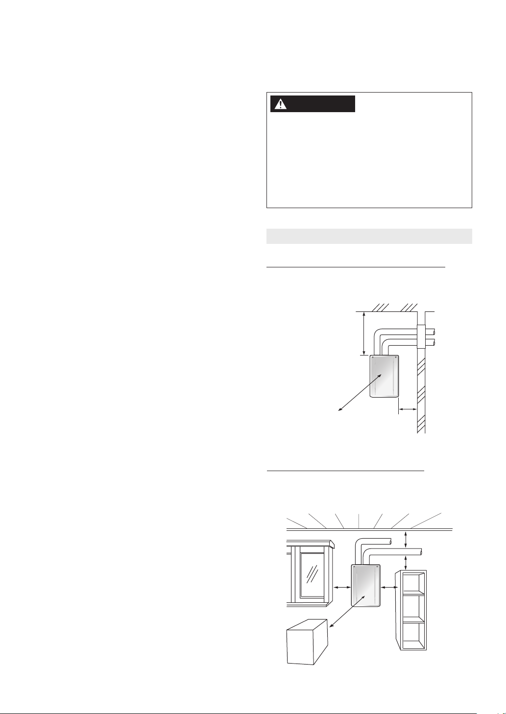
2. Hang the Water Heater on the Wall Mounting
Bracket.
Mounng
Bracket
(Upper)
Hang
After hanging the Water
Heater, you have the ability
to move either left or right
to position the Water Heater
in the appropriate spot.
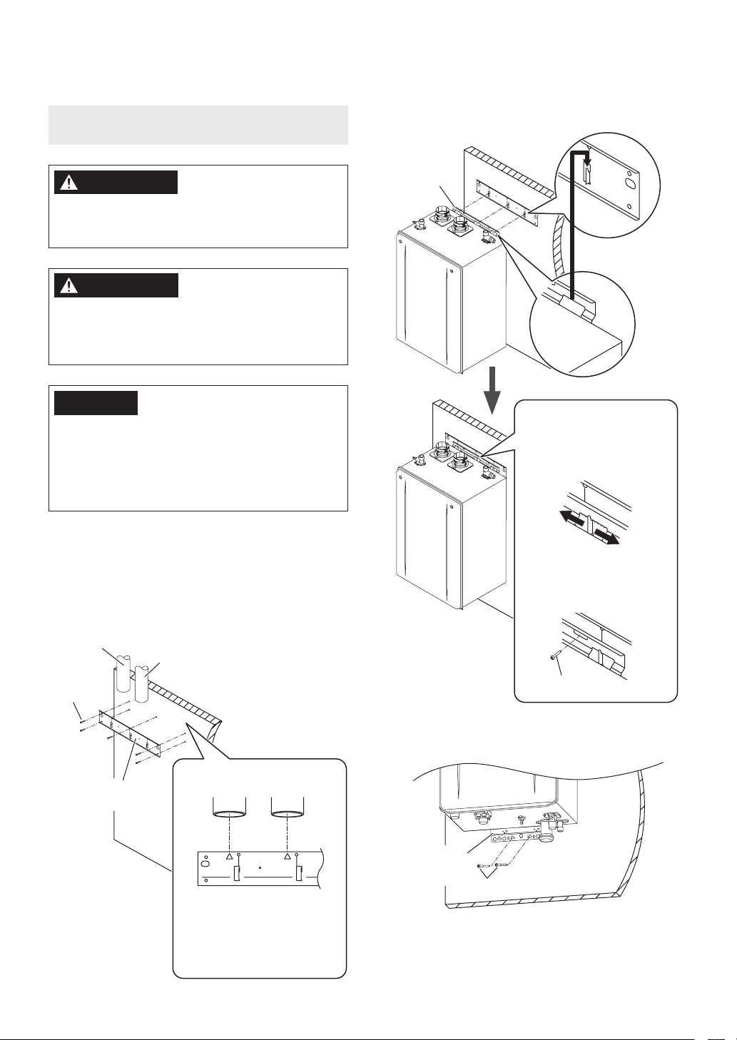
1. Ensure that the Wall Mounting Bracket is
leveled.
Drill holes for the Wall Mounting Bracket and
affix the Wall Mounting Bracket securely to the
wall by 5 screws.
Finally, make sure the bracket can support the
weight of the Water Heater.
Vent
Wall Mounting
Bracket
Exhaust
Vent
Intake
Vent
The bracket has marking to
assist with ensuring properly
aligned connections. Align the
intake and exhaust vent center
line with the corresponding
mark on the bracket.
Exhaust
Vent
Once positioned, a screw
(see below) can be fastened
to ensure no horizontal
movement will occur.
(Not supplied
from Noritz.)
3. Affix the Mounting Bracket (Lower) to the wall
by 2 screws.
Mounting
Bracket
(Lower)
Anchoring Screw
Installation of the Water Heater
15
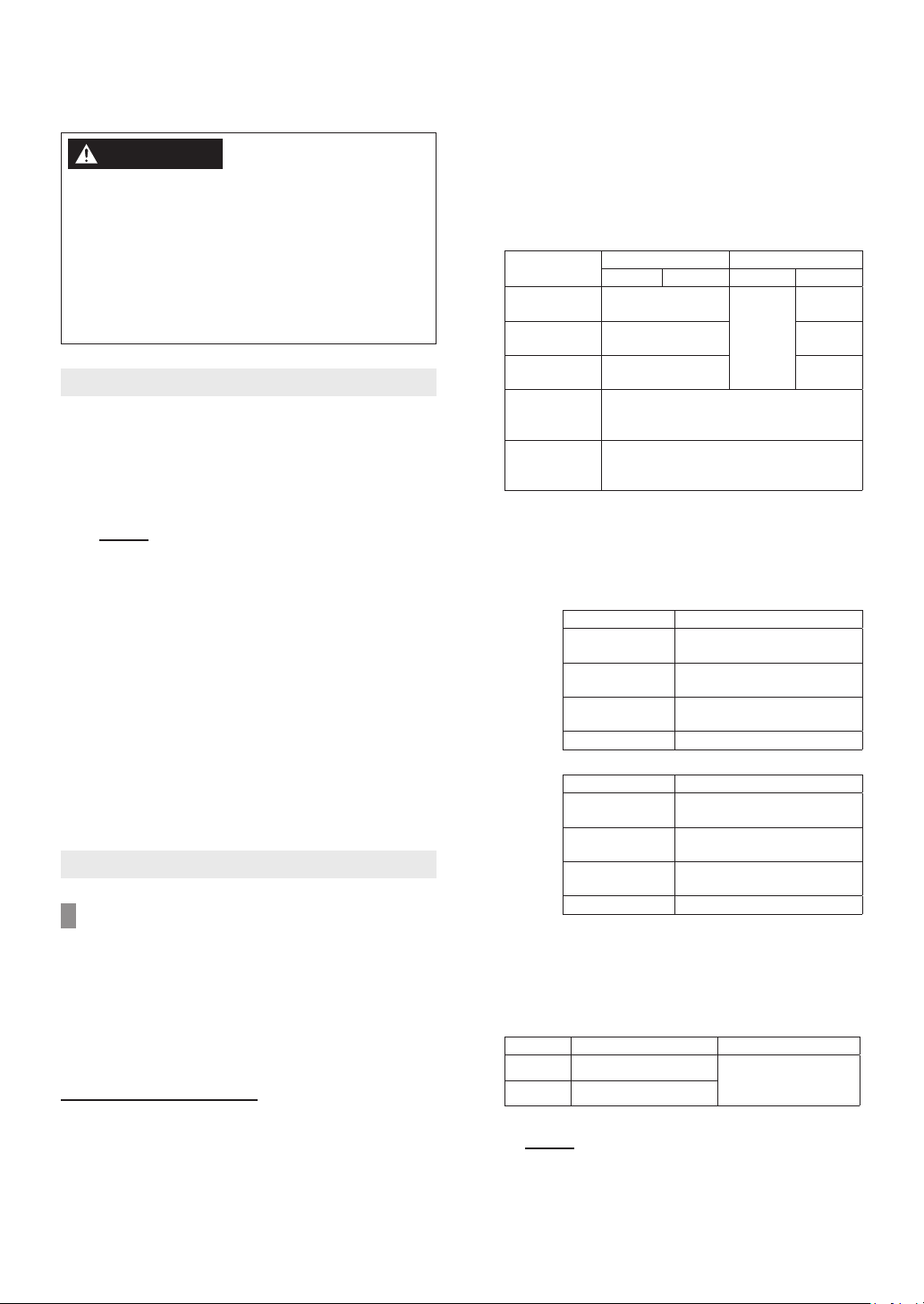
5.2 Elevation Adjustment Above 2,000 ft
t
• Adjust the DIP switches as illustrated in the table
below, if this Water Heater is installed at an
altitude of 2,000 ft (610 m) or higher.
• Disconnect the electrical power and then adjust
the DIP switches.
Refer to page 56 for the location of the DIP switch
bank and how to change the DIP switches.
Failure to perform this step will result a “73” code
displayed on the Remote Controller and a cease
in operation.
If this occurs, disconnect, then reconnect the
electrical power to the Water Heater to reset the
system.
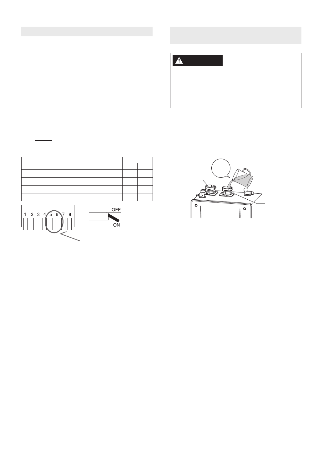
5.3 Filling the condensate container
with water
DANGER
Prior to initial start up, make sure that you fill
the condensate container with water.
This is to prevent dangerous exhaust gases from
entering the building.
Failure to fill the condensate container could
result in severe personal injury or death.
Follow the procedure described below to ensure
that the condensate container is filled with water.
NOTE
0-2,000 ft (0-610 m)
2,001-4,000 ft (611-1,219 m)
4,001-7,000 ft (1,220-2,134 m)
7,001-10,000 ft (2,135-3,048 m)
Do not change any other DIP switches.
High elevation adjustment
Here
ON = / OFF =
DIP switches
#5 #6
Fill the condensate container by pouring approx. 10
oz. (280 mL) of water into the exhaust flue on the
top of the Water Heater as illustrated below.
10 oz.
280 mL
Intake
Exhaus
If the vent pipe has already been installed:
After installing the condensate drain pipe, make
sure that the area around the Water Heater is well
ventilated; open a window or a door if necessary.
Then, operate the Water Heater and verify that
condensate is coming out of the condensate drain
pipe.
(During normal use of the Water Heater, condensate
will begin to discharge from the condensate drain
pipe within 15 minutes of use. However, depending
on the season and/or installation site conditions, it
may take longer.)
16
Installation of the Water Heater
6 Venting the Water Heater
6 Venting the Water Heater
WARNING
CARBON MONOXIDE POISONING
Follow all vent system requirements in
accordance with relevant local or state
regulation, or, in the absence of local or state
code, if in the U.S., refer to the National Fuel
Gas Code ANSI Z223.1 / NFPA 54 - latest edition,
and if in Canada, in accordance with the Natural
Gas and Propane Installation Code CSA B149.1
- latest edition.
6.1 Venting Installation Sequence
1. Install the Water Heater.
2. Determine the termination method—horizontal
or vertical, etc.
3. Determine proper location for wall or roof
penetration for each termination.
NOTE
4. Install termination assembly as described in
this manual or in the vent manufacturer’s
installation instructions.
If necessary, install Bird Screen (not supplied
with Water Heater).
5. Install combustion air and exhaust vent piping
from Water Heater to termination.
6. Slope the horizontal vent 1/4 in. upwards for
every 12 in. (305 mm) toward the termination.
7. Install supports and hanger straps allowing
for movement from expansion, or as per vent
pipe manufacturer’s instructions or local code
requirements.
6.2 General Requirements
6.2.1 Vent Piping Material
• This is a Category IV appliance.
Only vent materials approved for use with
Category IV appliances shall be used.
• Under normal conditions, this Water Heater
will not produce an exhaust flue temperature in
excess of 149°F (65°C).
For PVC/CPVC/PP material
Do not exceed maximum allowed vent
lengths as described in this manual.
• This Water Heater must be vented with plastic
pipe materials as specified in the table below.
Vent installations in Canada which utilize plastic
vent systems must comply with ULC S636.
[Exhaust Vent / Air Intake]
Material
Schedule 40
PVC
PVC-DWV ANSI/ASTM D2665
Schedule 40
CPVC
Polypropylene
(PP)*
System 1738TM
PVC Fuel Gas
Venting
United States Canada
Exhaust Air Intake Exhaust Air Intake
ANSI/ASTM D1785
ANSI/ASTM F441
Centrotherm - lnnoFlue®
(certified ULC S636),
DuraVent PolyPro® (certified ULC S636)
IPEX Management Inc.
(certified UL 1738)
ULC S636
Certified
Materials
Only
CSA
B137.3
CSA
B181.2
CSA
B137.3
* Only listed manufacture specified vent parts
may be used for this Water Heater.
Refer to the manufacture’s literature for
detailed information.
- Approved Vent Manufacture:
- Centrotherm - lnnoFlue® PP
Parts #
Single Wall Pipe
(2 in. / 3 in.)
Elbow
Termination**
Bird Screen IASPP02/03
ISVL02xx(UV)/03xx(UV),
ISEP02xx/03xx, ISIA0203
ISELL0287(UV)/0387(UV),
ISELL0245/0345
ISELL0287UV/0387UV,
ISTT0220/0320
- DuraVent PolyPro®
Parts #
Single Wall Pipe
(2 in. / 3 in.)
Elbow
Termination**
Bird Screen 2PPS-BG/3PPS-BG
2PPS-xxBL/3PPS-xxBL,
2PPS-xxL/3PPS-xxL
2PPS-E90(B)L/3PPS-E90(B)L,
2PPS-E45(B)L/3PPS-E45(B)L
2PPS-E90(B)L/3PPS-E90(B)L,
2PPS-T(B)L/3PPS-T(B)L
** Applicable vent termination are “90°
elbow” or “Tee type”. Concentric vent
termination of polypropylene are
prohibited.
[Pipe Cement / Primer]
Material United States Canada
PVC ANSI/ASTM D2564
CPVC ANSI/ASTM F493
ULC S636
Certified Materials
Only
• Schedule 40 PVC pipe may be used as the vent
material. If required by local code, use schedule
40/80 CPVC or PP.
NOTE
Use of cellular core PVC (ASTM
F891), cellular core CPVC, or Radel®
(polyphenylsulfone) in non-metallic
venting system is prohibited.
Venting the Water Heater
17
• Use only solid PVC / CPVC (schedule 40) or PP
pipe.
• 2 in. or 3 in. schedule 80 pipe may also be used
on this Water Heater, however the Btu/h input of
the Water Heater will be reduced by up to 9%.
• Maintain the same vent pipe diameter from the
Water Heater flue to the termination.
• In Canada, plastic vent systems must be certified
to ULC S636. The components of the certified
vent system must not be interchanged with other
vent systems or unlisted pipe/fittings.
• In Canada, specified primers and glues of the ULC
S636 certified vent system must be from a single
system manufacturer and not intermixed with
other system manufacturer’s vent system parts.
NOTE
Covering non-metallic vent pipe and
fittings with thermal insulation is
prohibited.
For 2 in. flexible PP material
• Flex Vent 2 in. Conversion Kit (EZ2-CK) must
be used when using 2 in. flexible PP pipe for
vent pipe installation. Refer to the instructions
provided with Flex Vent 2 in. Conversion Kit for
additional detail.
• During the installation of Flex Vent 2 in. Kit
(EZ2FVK-1 and EZ2FVK-2), ambient temperatures
must be greater than 40°F (5°C). Afterwards,
installation site ambient temperature must be
greater than -4°F (-20°C). Flex vent pipe breakage
may occur if these temperature requirements are
not observed.
• Only listed manufacturer specified vent parts may
be used for this Water Heater.
[Information regarding certified “Flexible vent
pipe and connections”]
- Flex Vent 2 in. Kit – 25 ft (EZ2FVK-1)
- Flex Vent 2 in. Kit – 35 ft (EZ2FVP35-3)
Standard(s)
Product
Brand name Living Engineering Co,Ltd.
ULC-S636-08 Standards for type BH Gas
Venting Systems
25 ft - Flex Pipe 2 in. - LE, Flex Vent 2 in.
Rigid 45 Elbow Set - LE, 35 ft - Flex Pipe
2 in. - LE
• Do not intermingle any other venting material
with allowable polypropylene venting mentioned.
• The Btu/h input of the Water Heater will be
reduced by up to 9% when maximum vent length.
For flexible pipe for chimney
• During the installation, ambient temperatures
must be greater than 40 °F (5 °C). Afterwards,
installation site ambient temperature must
be greater than -4 °F (-20 °C). Flexible vent
pipe breakage may occur if these temperature
requirements are not observed.
• Only listed manufacture specified vent parts
may be used for this appliance. Refer to the
manufacture’s literature for detailed information.
- DuraVent® - Flex Through Chimney w/ Air Intake
Exhaust
Intake
Exhaust
Intake*
Flex Chimney Lining Kit (3 in.): 3PPS-FKL,
Flex Length (3 in.): 3PPS-FLEXxx
Aluminum Flex Length (3 in.): 3DFA-xx,
Coupler (3 in.): 3DFA-FCP
Elbow (3 in.): 3PPS-E45L, 3PPS-E90L,
Single-Wall Pipe (3 in.): 3PPS-xxL
&
Appliance Adapter for PVC Coupler (2 in.):
2PPS-ADL,
Increaser: 2PPS-X3L
- Centrotherm - lnnoFlue® PP
Exhaust
Intake
Exhaust
Intake*
Chimney Kit (3 in.): IFCK03xx,
Flexible Pipe PP (3 in.): IFVL03xxx
Termination**: ISELL0387UV, ISTT0320,
Bird Screen: IASPP03
Single Wall Pipe (3 in.): ISVL03xx(UV),
ISEP03xx
&
Elbow (3 in.): ISELL0387UV, ISELL0345UV,
ISEL0387, ISEL0345,
Increaser: ISIA0203
* Recommended items.
** Applicable vent termination are “87° elbow” or
“Tee type”.
Concentric vent termination of polypropylene
are prohibited.
6.2.2 Installation Instructions
WARNING
CARBON MONOXIDE POISONING
• Failure to properly seal the vent system could
cause flue products to enter the living space.
• (For flexible pipe for chimney)
Handle the flexible vent carefully.
Dropping, Crushing and Stacking may cause
damage, and may result in fires, property
damage or exposure to Carbon Monoxide.
• Follow all general venting guidelines as outlined in
this manual.
• Clearance described in this document is the
minimum recommendation/required distance.
Take appropriate clearance according to the
situations of the site.
• Make sure the vent system is gas tight and will
not leak.
• Support the vent pipe with hangers at regular
intervals as specified by these instructions or the
instructions of the vent manufacturer.
• All piping must be fully supported. Use pipe
hangers at a minimum of 3 ft (0.9 m) intervals.
NOTE
Do not use the Water Heater to
support the vent piping.
18
Venting the Water Heater
• Ensure at least 3 ft (0.9 m) or
Exhaust and
Intake Flue
- Box wrench (5/16 in.)
more distance between the
near edge of the air intake
pipe or exhaust pipe to the
inside corner of a wall.
For PVC/CPVC/PP material
3 ft (0.9 m)
or more
Inside corner
For 2 in. flexible PP material
• Flex Vent 2 in. Kit may be used only in
accordance with the installation manual
included with the kit.
• Flex Vent 2 in. Kit can be installed at zero
clearance to combustible materials.
• The Water Heater can be started up immediately
after Flex Vent 2 in. Kit is installed and inspected.
• Flex Vent 2 in. Kit systems expand and contract
slightly during heating cycles and must be
installed following included instructions.
• Flex Vent 2 in. Kit cannot be painted.
• When installing N-Flex vent, pitch is required as
detailed in Flex Vent 2 in. Kit installation manual.
• When preparing and assembling the pipe,
follow instructions as provided by the pipe
manufacturer. In general, the following practices
must be observed:
- Squarely cut all pieces of pipe.
- Remove all burrs and debris from joints and
- All joints must be properly cleaned, primed,
• PVC, CPVC or PP pipe has been approved for
use on this Water Heater with zero clearance to
combustibles.
• The pipe shall be installed so that the first 3 ft
(0.9 m) of pipe from the Water Heater flue outlet
is readily accessible for visual inspection.
• When attaching the piping to the Water Heater,
use the appropriate primer and cement to ensure
a proper seal.
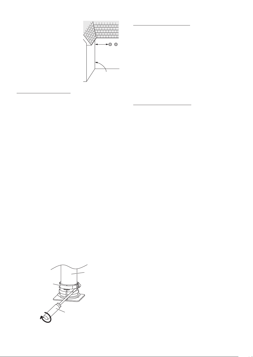
[How to tighten the Vent Pipe]
1. Continue to insert the Vent Pipe until it reaches
• The Vent Pipe will be inserted approximately
2. Secure the Vent Pipe by tightening the band
• The tightening torque shall be the following:
- For PVC/CPVC pipe: between 16 and 20 in lb
- For PP pipe: between 12 and 15 in lb
fittings.
and cemented. Use only cement and primer
approved for use with the pipe material as
outlined on page 17.
to the base of the Water Heater Exhaust and
Intake Flue.
2.3 in. (60 mm).
using a screwdriver.
Vent Pipe
Screwdriver
- Flat head
For flexible pipe for chimney
• Every venting system must be properly planned
and installed for optimum performance and
safety. A flexible pipe installation always begins
with an inspection of the existing masonry
chimney (Chimney must be clean, sized correctly,
properly constructed and in good condition, if
being installed in a chimney as a liner). Inspect
chimney to make certain it is constructed
according to the latest revision of the NFPA211.
Local codes may differ from this code and should
be checked. Where there is a conflict, the local
code will prevail. In Canada refer to the National
Building Code or CSA-A405 as applicable.
• Refer to manufacturer’s instructions for assembly
of all flexible components including the chimney
cap and adaptor to rigid pipe at base of masonry
Chimney.
• Ensure none of the vent pipes and chimneys are
damaged or blocked.
• Do not use an existing chimney as a raceway for
a flue pipe if another appliance or fireplace is
vented through the chimney, and do not have any
connections inside the chimney chase.
• When using an inoperative chimney as a means
of a chase for the vent system, the surrounding
space within the chimney cannot be used to draw
combustion air or vent another appliance.
• The remaining space surrounding a chimney
liner, the flexible pipe within a masonry, metal
or factory-built flue shall not be used to supply
combustion air to the Water Heater. A separate
combustion air intake pipe routed back to the
Water Heater can be used in the remaining space
if required, the Water Heater venting system
is approved for zero clearance, and can be run
directly beside the combustion air intake pipe.
Bolt or screw joints together to avoid sag.
• Flexible pipe vertical offsets must not exceed 45°
and are limited to a maximum number of 2.
• Connect flue pipe to the chimney with the
shortest possible length of flue pipe.
• Slope the horizontal vent 1/4 in. upwards for
every 12 in. (300 mm) toward the chimney from
the Water Heater.
Venting the Water Heater
19
• Check and confirm that there is no tension to
the flexible pipe by hanging or suspending of
anything.
• Check vent piping at least once a season. Verify
vent pipe connections to chimney are secure and
no obstructions are present. If vent piping shows
sign of leaking, replace it immediately.
6.2.3 Termination Considerations
• Do not store hazardous or flammable substances
near the vent termination and check that the
termination is not blocked in any way.
• Steam or condensed water may come out from
the vent termination. Select the location for
the termination as to prevent injury or property
damage.
• If snow is expected to accumulate, make sure the
termination will not be covered with snow or hit
by falling lumps of snow.
• (For PVC/CPVC/PP material) A bird screen must
be installed on the vent terminations to prevent
debris or animals from entering the piping. These
screens are not supplied with the Water Heater
and must be purchased separately.
Vent Material Bird Screen Parts #
2 in. (50 mm) PVC or CPVC VT2-PVCS
3 in. (75 mm) PVC or CPVC VT3-PVCS
Centrotherm - 2 in. (50 mm) PP IASPP02
Centrotherm - 3 in. (75 mm) PP IASPP03
DuraVent - 2 in. (60 mm) PP 2PPS-BG
DuraVent - 3 in. (80 mm) PP 3PPS-BG
6.2.4 Maximum Vent Length
• This Water Heater has been designed to be
vented with either 2 in. (50 mm) or 3 in. (75 mm)
PVC, CPVC, PP, or 3 in. (75 mm) flexible pipe for
chimney. If you use Flex Vent 2 in. Conversion Kit,
you must use 2 in. flexible PP.
• The minimum total vent length including
horizontal and vertical vent runs should not be
less than:
- PVC/CPVC/PP, 3 in. (75 mm) flexible pipe for
chimney: 3 ft (0.9 m)
- 2 in. flexible PP: 5 ft (1.5 m)
• The Water Heater can be adjusted to
accommodate longer vent runs; refer to the table
below. Do not exceed the maximum vent length.
• Disconnect the electrical power and then adjust
the DIP switches according to the vent condition
noted in the tables below.
Refer to page 56 for the location of the DIP switch
bank and how to change the DIP switches.
Failure to perform this step will result a “73” code
displayed on the Remote Controller and a cease
in operation.
If this occurs, disconnect, then reconnect the
electrical power to the Water Heater to reset the
system.
NOTE
• When adjusting the DIP switches
for longer vent runs, the Btu/h
input of the Water Heater will be
reduced by up to 9%.
• Do not change any other DIP
switches.
• The following termination can also be used.
-
Termination Manufacturer: IPEX Management Inc.
- Item description
Item Item #
Universal Concentric Vent Kit (UCVK)*
(PVC ULC S636/UL 1738 - Certified for
use in both Canada and USA)
IPEX Low Profile Termination Kit**
(PVC ULC S636/UL 1738 - Certified
for use in both Canada and USA)
NOTE
Below are additional models
2 in.
3 in.
PVC-UCVK
(397007)
PVC-2LPT
(397100)
PVC-3LPT
(397101)
approved for use by Noritz and
supplied by IPEX. Refer to the IPEX
literature or web site for additional
details.
* Universal Concentric Vent Kit :
<USA> #397256 - PVC System 1738
<Canada> #196256 - PVC System 636
#197256 - CPVC System 636
** Low Profile Termination Kit :
<USA> #397984 - 2” PVC System 1738
#397985 - 3” PVC System 1738
<Canada> #196984 - 2” PVC System 636
#196985 - 3” PVC System 636
Maximum Vent Length Configurations (For PVC/
CPVC/PP material)
• The maximum vent length when using 2 in. (50
mm) pipe is 65 ft.
• The maximum vent length when using 3 in. (75
mm) pipe is 150 ft.
Both maximum lengths are reduced by the
number of elbows used, as shown in the following
table:
Maximum equivalent
Vent
diameter
2 in. 65 ft (20 m) 6
3 in. 150 ft (46 m) 15
*1 The maximum vent length includes elbows.
*2 Not including the termination.
vent length*
V (Vertical)
H (Horizontal)
1
Maximum #
+
of elbows*
Equivalent
2
length
90° elbow:
5 ft (1.5 m)
45° elbow:
3 ft (0.9 m)
20
Venting the Water Heater

[DIP Switch Adjustment]
Vent length condition
①Less than 33 ft using 2 in. (50 mm) pipe
②33 ft or more using 2 in. (50 mm) pipe
③Less than 75 ft using 3 in. (75 mm) pipe
④75 ft or more using 3 in. (75 mm) pipe
ON = / OFF =
DIP switches
#7 #8
Here
[Vent length Calculation example]
Step 1:
Vent Diameter
2 in.
Step 2:
Straight pipe length
(Vertical length + Horizontal length)
17 ft
Step 3:
Number of elbows
90° elbows: 2
45° elbows: 2
Step 4:
Calculate equivalent length
90° elbows: 2 × 5 ft = 10 ft
45° elbows: 2 × 3 ft = 6 ft
Step 5:
Total vent length
(Add Step 2 and Step 4 together)
17 ft + 16 ft = 33 ft
Step 6:
Check [DIP Switch Adjustment] and select DIP
switch settings.
②[33 ft or more using 2 in. (50 mm) pipe]
(i.e., turn ON DIP switch #7)
Maximum Vent Length Configurations (For Flex
Vent 2 in. Conversion Kit)
Maximum Vent Length Example:
• Actual Vent Length = 13 ft (3.9 m) (with DIP
switch set at “Short length” condition)
• Actual Vent Length = 25 ft (7.5 m) (with DIP
switch set at “Long length” condition)
ON = / OFF =
Vent length
Short length 5 ft (1.5 m) - 15 ft (4.5 m)
Long length 15 ft (4.5 m) - 35 ft (10.5 m)
DIP switches
#7 #8
Maximum Vent Length Configurations (For flexible
pipe for chimney)
[DuraVent® - Flex Through Chimney w/ Air Intake
(Only 3 in.)]
The vent length condition setting depends on
the flexible pipe length, the rigid pipe length and
number of elbows. Calculate an each ventilation
system equivalent length, then adjust the DIP
switch.
ON = / OFF =
Vent
length
condition
Short
length
Long
length
* The maximum vent length includes elbows.
switch
Maximum equivalent
DIP
#7
vent length*
V (Vertical)
+
H (Horizontal)
< 50 ft (15 m)
50 ft (15 m)–75 ft (22.5 m)
Equivalent
length
Flexible pipe:
1 ft (0.3 m)
Rigid pipe:
1 ft (0.3 m)
90° elbow:
5 ft (1.5 m)
45° elbow:
3 ft (0.9 m)
Here
• Equivalent vent length calculation example:
[Example 1]
- Vent Size: 3 in.
- V (Vertical length): 20 ft
- H (Horizontal length): 6 ft
- 90° elbow: 2
1 ft × 20 + 1 ft × 6 + 5 ft × 2 = 36 ft
Select “Short length”
[Example 2]
- Vent Size: 3 in.
- V (Vertical length): 35 ft
- H (Horizontal length): 10 ft
- 90° elbow: 3
1 ft × 35 + 1 ft × 10 + 5 ft × 3 = 60 ft
Select “Long length”
Here
Venting the Water Heater
21
 Loading...