

Noritz IHK-NRCP Installation And Instruction Manual
# Parts Shape Q’ty
1
Temperature Sensor
(2 ties included)
1
2
Wire for Temperature Sensor
(4.0 ft [1.2 m])
1
3 Push Button Switch 2
4 Instruction 1
3. Installation
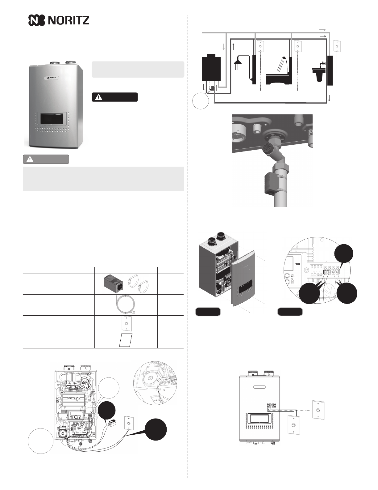
1) Schematic diagram
2) Wiring
①
Turn off both gas and water supply to the water heater. Turn the power off.
②
Remove the front cover by loosening the 4 screws. (Figure 1)
3) Wiring for Push Button Switches
③
Connect both push button switch and temperature sensor to the connector on the
terminal block. See Figure 2.
④
Close the front cover with secure 4 screws.
When you connect the push button switches to the terminal block, you can run cables from
each switch directly to the terminal block and connect them to the same terminal. Or, you can
run a common branch circuit that runs from the terminal block and connect each switch to the
branch.
Multiple switches connected directly to the same terminal at the terminal block.
Read this manual carefully and failure to follow these
instructions exactly could result in a re or explosion, serious
bodily injury and/or property damage. Installation must be
performed by a qualied plumber, a licensed gas tter, or a
professional technician in accordance with all local codes.
Improper installation and operation by an unqualied person
will void the warranty.
Electrical Shock Hazard
Do not turn the power on until electrical wiring is nished. Disconnect the power before servicing.
Failure to do so may result in death or serious injury from electrical shock.
1. About this Kit
NORITZ IHK-NRCP offers the most efficient way to save energy and water by adding Temperature
Sensor and setting on the panel.
This kit is designed to deliver hot water to your entire home with the press of a button (within a few
minutes). There are no standby losses, no stack losses, and no need for extra storage tanks.
This kit can be used only on an external recirculation system with a dedicated return line.
■ Items included in the kit
Before installation, verify that all the items below are included .
Kit# IHK - NRCP
Rev.10/16
On Demand Recirculation Installation
and Instruction Manual
WARNING
CAUTION
Figure 2Figure 1
Water
Heater
Return Line
Cold Water Line
Push
Button
Switch
#3
Push
Button
Switch
#1
Push
Button
Switch
#2
Hot Water Line
Note> It may take a few minutes depending on the length of the pipe to
prepare hot water to the desired xture.
Wires for Push Button Switches and Temperature Sensor should be connected to the terminal block
located on the right side of the control panel.
2. Overall installation schematic
Wires
Aftermarket
Purchase
Wires
Included
in this kit
Push
Button
Switch
“A” Wiring Throughway
Temperature
Sensor
Wiring
Throughway
See Detail “A”
Terminal
Block
G
Temperature
Sensor
2 Wires
from
Temperature
Sensor
Terminal
Block
2 Wires
from
Push Button
Switches
Return Connection
Install temperature sensor
as close as possible to the return
connection
Applicable for NRCP1112/982 series only.
5. Installing temperature sensor on recirculation system
The sensor should be installed as close to the return connection of the unit as possible in order
to measure the return temperature accurately.
1) Open the cover of temperature sensor package. See Figure 3.
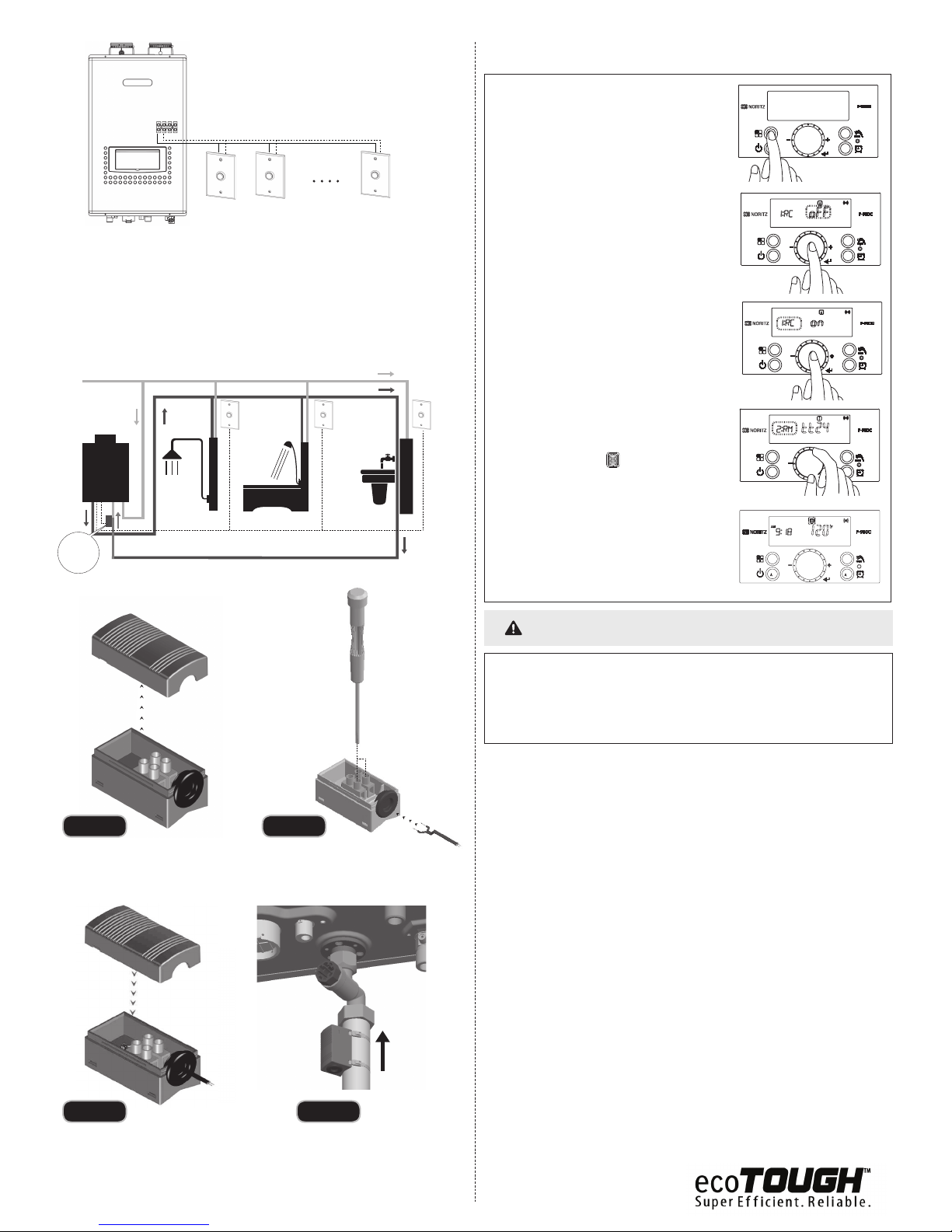
6. Setting on the control panel
7. How to Use
1) Turn the power off on the remote.
2) Press and hold the 'Function Button' to enter
'Installer Mode', '[1:RC]' will be displayed.
3) Press the 'Dial Button' so 'oFF' is ashing. (Default
setting is 'oFF' and recirculation function is not
activated.)
4) Turn the 'Dial Button' clockwise so 'on' is ashing.
(This will active the recirculation function.)
5) Press the 'Dial Button' to store the current setting
mode and return back to ‘Installer Mode’.
6) Turn the 'Dial Button' to '[2:RM]' then press the 'Dial
Button' to save the setting.
7) Turn the 'Dial Button' to '[tt24]' (On Demand
Recirculation Mode) then press the 'Dial Button' to
save the setting.
Note> ① '[tt24]' (On Demand Recirculation Mode)
cannot be accepted if the Temperature
Sensor is not connected to the terminal
block.
②
You can nd ' ' icon on the display
panel properly setting and connection the
Temperature Sensor.
1) Before hot water is required, press any of the push button switches.
2) Pump will begin to circulate and prime the lines with hot water. The pump will continue to
run until water reaches the most remote xture.
Note> The pump run time and delivery time are determined by water pipe distance and
size. Longer runs will result in longer run times.
3) Pump will shut down automatically once hot water is available.
4) Do not repeatedly press the push button switch.
To activate the function, follow the procedure below.
Water
Heater
Return Line
Cold Water Line
Push
Button
Switch
#3
Push
Button
Switch
#1
Push
Button
Switch
#2
Hot Water Line
Figure 3
Figure 5
Figure 4
Figure 6
2) Connect cables to terminal block. See Figure 4.
3) Close the cover. See Figure 5.
4) Install the temperature sensor:
Normal recirculation control is overwritten by the following:
1. Set to External recirculation automatically.
2. Recirculation is initiated by pressing a Push Button Switch.
3. Disables automatic timer function.
4. When the temperature reaches 102°F at the Temperature Sensor, recirculation will stop.
5. Or when 5 minutes have passed after pressing the Push Button Switch, recirculation will stop.
Multiple switches connected to a common branch circuit.
Note> ① You can connect up to 10 push button switches to one terminal.
②
Use cables with a diameter of AWG24 or greater.
③
Make sure that the total cable length does not exceed 328 feet (100 meters).
① Fasten to the pipe using the included stainless steel tie bands.
②
Temperature sensor must be installed in the vertical position.
③
Sensor orientation must be installed as pictured. See Figure 6.
G
Temperature
Sensor
NOTICE
To return
connection
 Loading...