

Noritz ecoTOUGH NRC98-DV, ecoTOUGH NRC83-DV Installation Manual
NORITZ AMERICA
Installation Manual
CORPORATION
CONDENSING TANKLESS GAS WATER HEATER
NRC98-DV
(Indoor Installation)
NRC83-DV
Potential dangers from accidents during installation and use are divided into the following three
categories. Closely observe these warnings, they are critical to your safety.
DANGER indicates an imminently hazardous situation which,
DANGER
WARNING
CAUTION
WARNING:
causing property damage, personal injury or death.
Prohibited
If the information in this manual is not followed exactly, a re or explosion may result
if not avoided, will result in death or serious injury.
WARNING indicates a potentially hazardous situation which,
if not avoided, could result in death or serious injury.
CAUTION indicates a potentially hazardous situation which,
if not avoided, may result in minor or moderate injury.
Disconnect
Power
Ground
Be sure to do
CAUTION
Requests to Installers
• In order to use the water heater safely, read this installation manual carefully, and follow the installation instructions.
• Failures and damage caused by erroneous work or work not as instructed in this manual are not
covered by the warranty.
•
Check that the installation was done properly in accordance with this Installation Manual upon completion.
•
After completing installation, please either place this Installation Manual in a plastic pouch and
attach it to the side of the water heater (or the inside of the pipe cover or recess box if applicable),
or hand it to the customer to retain for future reference. Also, be sure to ll in all of the required
items on the warranty and to hand the warranty to the customer along with the Owner's Guide.
FOR USE IN RESIDENTIAL OR MANUFACTURED HOME
APPLICATIONS.
CERTIFIED
R
Low NOx
Approved by
SCAQMD
Installation must conform with local codes, or in the absence of local codes,
the National Fuel Gas Code, ANSI Z223.1/NFPA 54- latest edition and/or
CSA B149.1, Natural Gas and Propane Installation Code (NSCNGPIC).
When applicable, installation must conform with the Manufactured
Home Construction and Safety Standard, Title 24 CFR, Part 3280 or the
Canadian Standard CAN/CSA-Z240 MH Mobile Homes, Series M86.
Noritz America reserves the right to discontinue, or change at any
time, the designs and/or speci cations of its products without notice.
SBA8834
Rev. 08/11
*SBA8834*
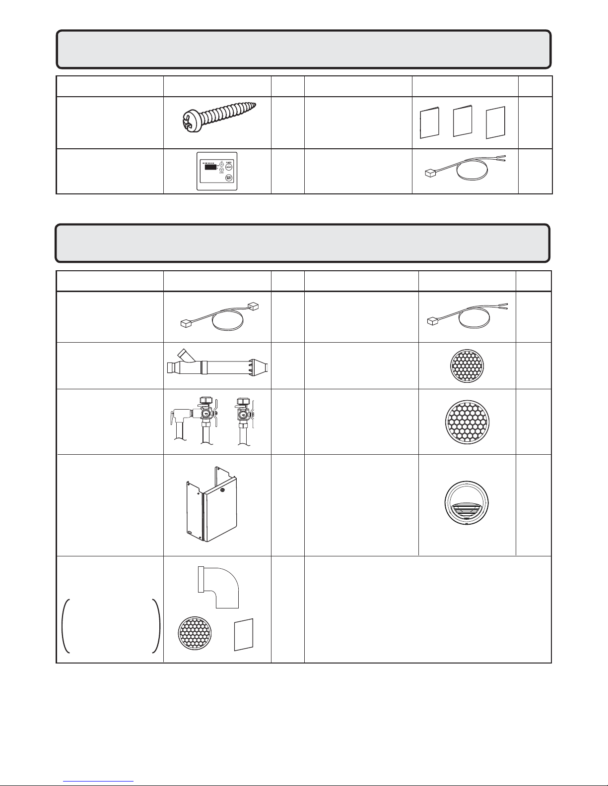
Included Accessories
1.
The following accessories are included with the unit.
Check for any missing items before starting installation.
Part Shape
Tapping Screw
Remote Controller
(See p. 29)
Optional Accessories
2.
Quick Connect Cord
(QC-2)
3" (75mm)
PVC Terminal
VK3-H-PVC
Q’ty
5
1
Q’ty
1
1
ShapePart
Owner's Guide, Warranty,
Installation Manual
(this document)
Remote Controller
Cord (6ft (2m))
The accessories listed below are not
included with the units, but may be necessary
for installation.
ShapePartPart Shape
Remote Controller
Cord (26ft (8m))
Bird Screen for
3" (75mm) PVC
VT3-PVCS
Q’ty
1
each
1
Q’ty
1
2
Isolation Valves
(includes pressure
relief valve)
Pipe Cover
(PC-3S)
SVConversionKit
(#SV-CK-3)
・90Elbow
・BirdScreen
・
InstallationManual
(CheckList)
1
each
1
1
each
Bird Screen for
4" (100mm) PVC
VT4-PVCS
3" (75mm) / 4" (100mm)
Horizontal Hood
Termination PVT-HL
Note: Additional vent pieces are available; consult the latest product catalogue for details.
2
2
2
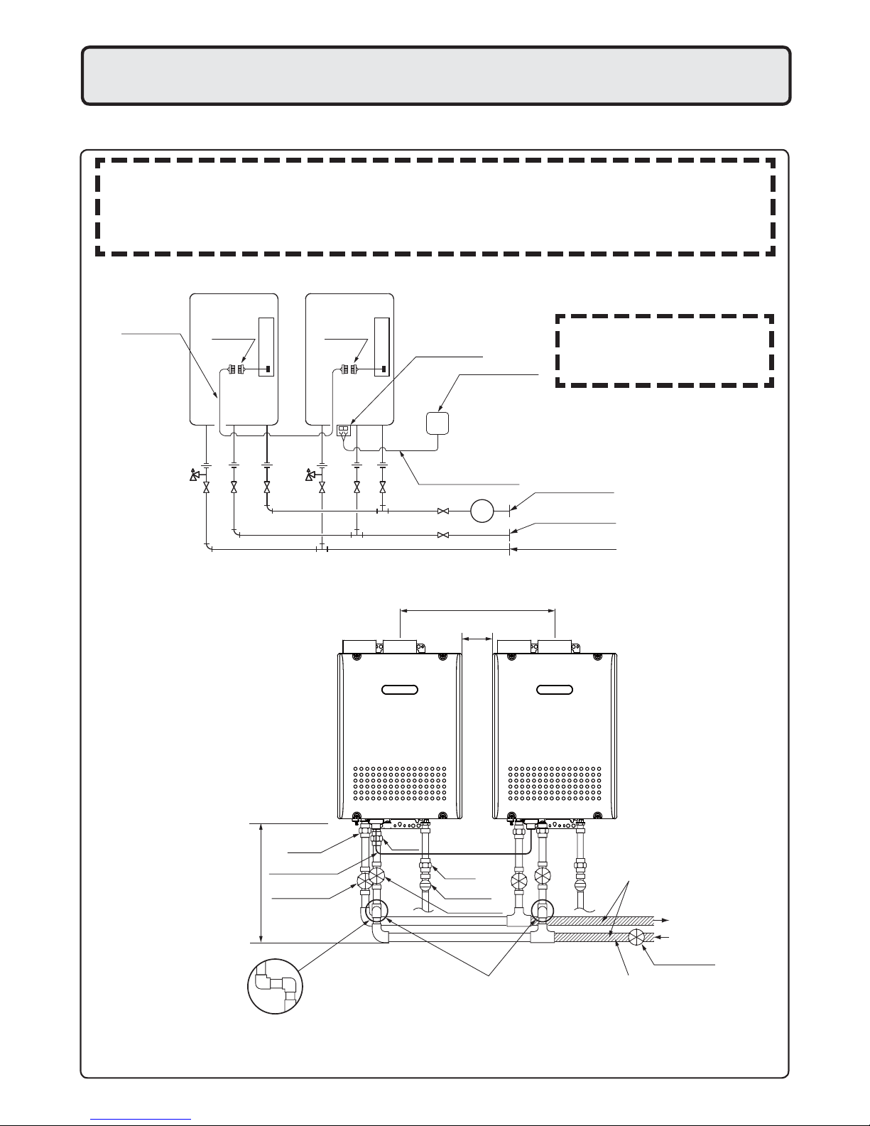
Union
Make this distance as short
as possible.
* The hot water temperature
will become unstable as the
pipe length increases.
Distance at center: 20.3 - 36.3 in. (515 - 922mm)
Quick Connect Cord
Union
Gas Valve
Union
Shutoff Valve
Shutoff Valve
Hot Water
Shutoff Valve
Cold Water
Distance on sides
2 - 18 in. (50 - 457mm)
Leave enough clearance around the plumbing to
apply insulation. It will be necessary to add
bends to the piping to ensure that this clearance
is available.
Size the piping to allow for the
maximum flow rates of the units.
The backflow preventer is
put up before it diverges.
3.
Quick Connect Multi System Installation
• The Quick Connect Multi System allows the installation of two units together utilizing only the Quick
Connect Cord.
The Quick Connect Cord is 6 ft.(2m) long. Install the units 2-18" (50 - 457mm) apart from each
other to ensure the cord will be able to reach between the units. (See Typical Plumbing diagram).
(If the distance between the two units is too great, not only will the cord not be able to reach,
but the water temperature may also become unstable because of the difference in pipe length
between the two units).
System Diagram
Quick Connect
Cord
Cord
Connector
Typical Plumbing
Cord
Connector
Terminal Block
Remote Controller
Remote Controller Cord
G
* When connecting two units, use only a
single remote controller.
Note: Connect the remote
controller to only one
of the units.
Gas Supply Piping
Cold Water Supply
Hot Water
• Insulate the hot water piping to prevent heat loss. Insulate and apply heating materials to the
cold water supply piping to prevent heat loss and freezing of pipes when exposed to excessively
cold temperatures.
3
Before Installation
4.
DANGER
Checkup
• Check the xing brackets and vent pipe yearly for damage or wear. Replace if necessary.
WARNING
Precautions on Vent Pipe Replacement
• The vent system will almost certainly need to be replaced when this appliance is being installed.
Only use vent materials that are speci ed in this Installation Manual for use on this appliance. Refer
to the "Vent Pipe Installation" section for details. If PVC, CPVC, or Category IV listed pipe is already
installed, check for punctures, cracks, or blockages and consult with the vent pipe manufacturer
before reusing.
Improper venting may result in res, property damage or exposure to Carbon Monoxide.
Snow Precaution
• If this product will be installed in an area where snow is known to accumulate, protect the vent
termination from blockage by snow drifts or damage from snow falling off of roofs.
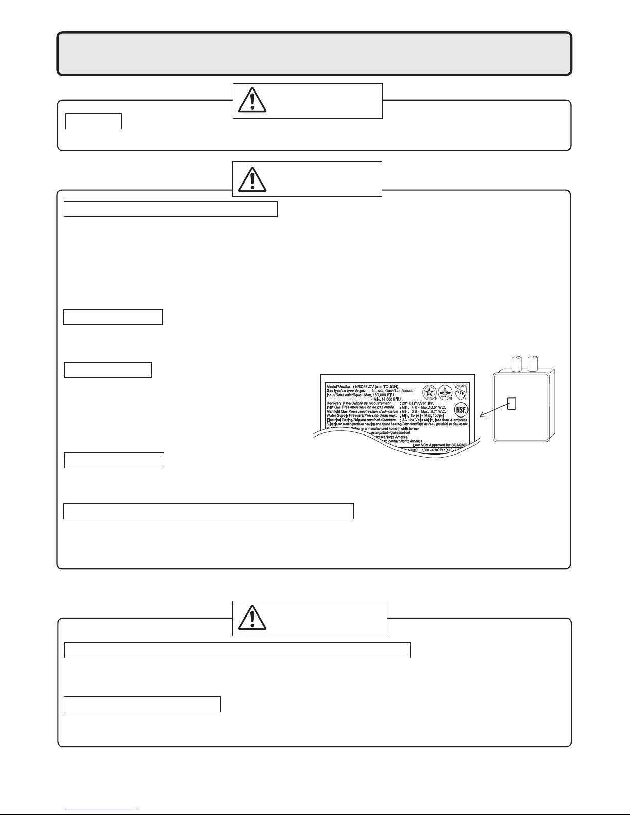
Check the Gas
• Check that the rating plate indicates the
correct type of gas.
• Check that the gas supply line is sized for
180,000 Btuh for NRC98-DV,
157,000 Btuh for NRC83-DV.
Check the Power
• The power supply required is 120VAC, at 60Hz.
Using the incorrect voltage may result in re or electric shock.
Use Extreme Caution if Using With a Solar Pre-Heater
• Using this unit with a solar pre-heater can lead to unpredictable output temperatures and
possibly scalding. If absolutely necessary, use mixing valves to ensure output temperatures do
not get to scalding levels. Do not use a solar pre-heater with the quick-connect multi-system.
CAUTION
Do Not Use Equipment for Purposes Other Than Those Speci ed
• Do not use for other than increasing the temperature of the water supply, as unexpected accidents
may occur as a result.
Check Water Supply Quality
• If the water supply is in excess of 12 grains per gallon (200 mg/L) of hardness, acidic or otherwise
impure, treat the water with approved methods in order to ensure full warranty coverage.
4
Choosing Installation Site
5.
* Locate the appliance in an area where leakage from the unit or connections will not result in damage
to the area adjacent to the appliance or to the lower oors of the structure. When such locations
cannot be avoided, it is recommended that a suitable drain pan, adequately drained, be installed
under the appliance. The pan must not restrict combustion air ow.
DANGER
• Locate the vent terminal so that there are no obstacles around the termination and so that exhaust
can't accumulate. Do not enclose the termination with corrugated metal or other materials.
WARNING
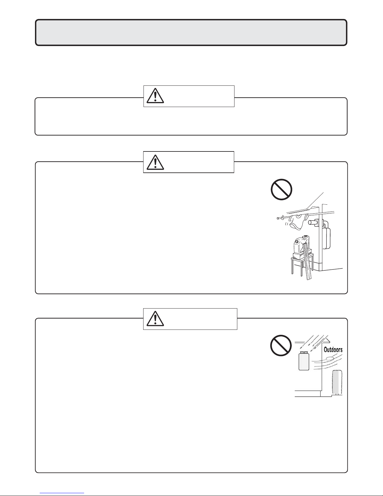
• Avoid places where res are common, such as those where gasoline,
benzene and adhesives are handled, or places in which corrosive gases
(ammonia, chlorine, sulfur, ethylene compounds, acids) are present.
Using the incorrect voltage may result in re or cracking.
Prohibited
• Avoid installation in places where dust or debris will accumulate.
Dust may block the air-supply opening, causing the performance of the
device fan to drop and incomplete combustion to occur as a result.
• Avoid installation in places where special chemical agents
(e.g., hair spray or spray detergent) are used.
Ignition failures and malfunction may occur as a result.
• Carbon Monoxide Poisoning Hazard. Do not install this water heater in a
recreational vehicle or on a boat.
CAUTION
• The water heater is designed for indoor installation only. Never install it
outdoors or in a bathroom, it may be damaged or a re may be caused.
• Consult with the customer concerning the location of installation.
• Install the water heater in an area that allows for the proper clearances
to combustible and noncombustible construction. Consult the rating
plate on the appliance for proper clearances.
• Do not install the water heater in a place where it may be threatened by
falling objects, such as under shelves.
Prohibited
• The water heater must be installed in a place where supply and exhaust
pipes can be installed as directed.
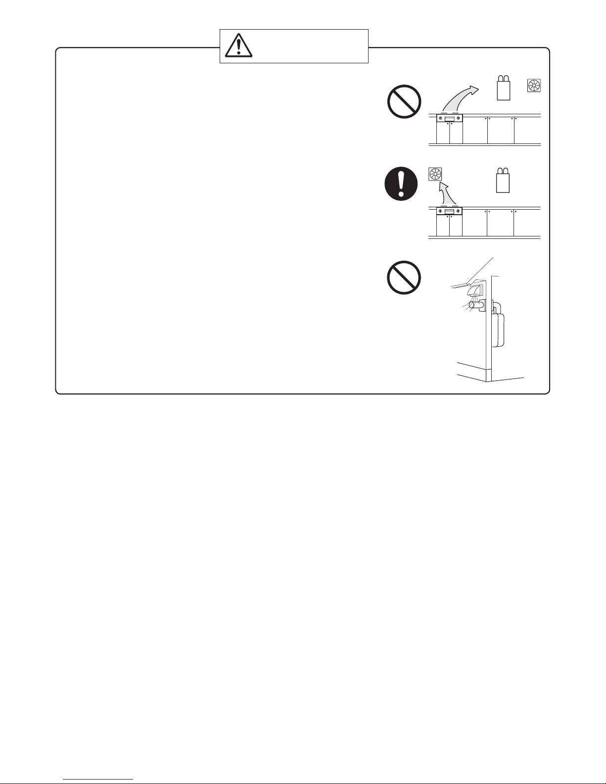
• Do not install the water heater where the exhaust will blow on outer walls
or material not resistant to heat. Also consider the surrounding trees and
animals.
The heat and moisture from the water heater may cause discoloration of
walls and resinous materials, or corrosion of aluminum materials.
5
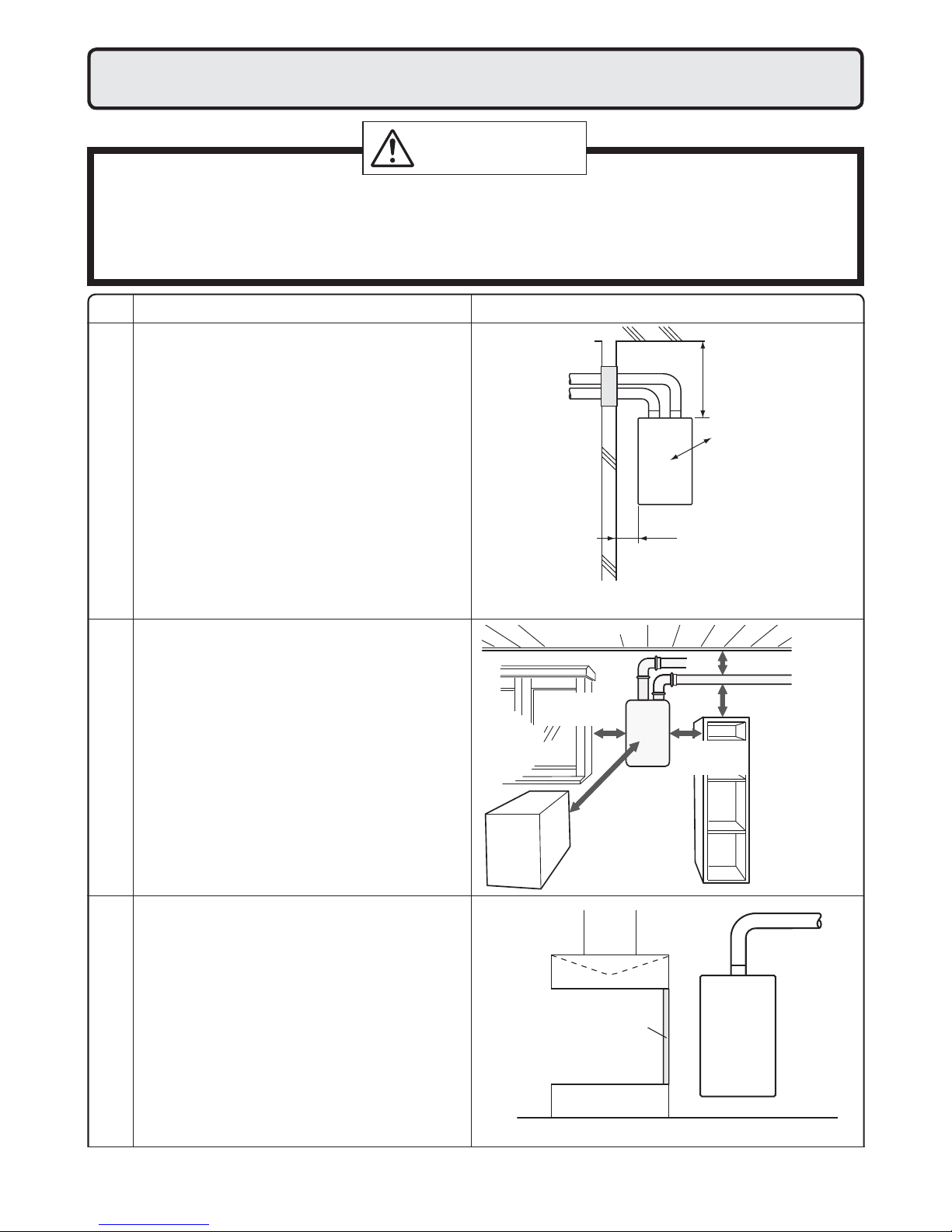
CAUTION
• Avoid installation above gas ranges or stoves.
• Avoid installation between the kitchen fan and stove. If oily
fumes or a large amount of steam are present in the installation
location, take measures to prevent the fumes and steam from
entering in the equipment.
• Install in a location where the exhaust gas ow will not be affected by fans or range hoods.
• Take care that noise and exhaust gas will not affect neighbors.
Avoid installation on common walls as the unit will make some
operational noises while it is running.
• Before installing, make sure that the exhaust ue termination will
have the proper clearances according to the National Fuel Gas
Code (ANSI Z223.1).
Prohibited
Be sure to do
Prohibited
State of California: The water heater must be braced, anchored or strapped to avoid moving during an
earthquake. Contact local utilities for code requirements in your area or call: 1-866-766-7489 and
request instructions.
The Commonwealth of Massachusetts: The water heater can be used for hot water only and not in a
combination of domestic and space heating.
For Venting Manufacturers Requirements, see websites or phone numbers listed below:
Noritz N-Vent www.noritz.com
6
Installation Clearances
6.
WARNING
Before installing, check for the following:
Install in accordance with relevant building and mechanical codes, as well as any local, state or
national regulations, or in the absence of local and state codes, to the National Fuel Gas Code
ANSI Z223.1/NFPA 54 – latest edition. In Canada, see NSCNGPIC for detailed requirements.
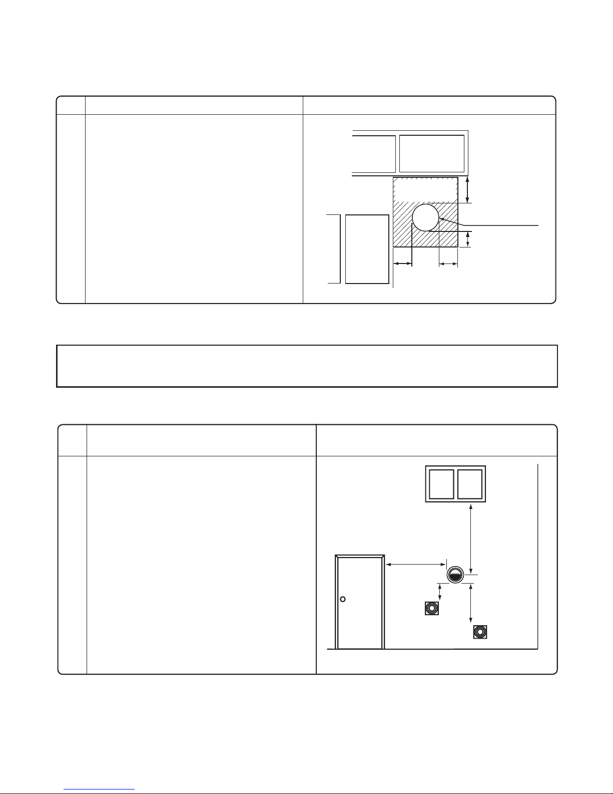
Item
• Maintain the following clearances
from both combustible and
non-combustible materials.
Distance from combustibles
• If possible, leave 8" (200mm) or more on
either side of the unit to facilitate inspection.
• If possible, leave 24" (600mm) or more in
front of the unit to facilitate maintenance
and service if necessary.
• If possible, leave 3" (75mm) or more
above and below the vent pipe to facilitate
repair/inspection
inspection and repair if necessary
Securing of space for
Check Illustration
Distance from
the side
8" (200mm)
or more
24" (600mm)
or more
12" (300mm)
or more
4" (100mm)
or more
2" (50mm)
or more
3" (75mm) or more
3" (75mm) or more
8" (200mm)
or more
<When the indoor air supply>
• If the unit will be installed in the vicinity of
a permanent kitchen range or stove that
has the possibility of generating steam
that contains fats or oils, use a dividing
plate or other measure to ensure that the
unit is not exposed to air containing such
impurities.
Cooking Equipment
* The dividing plate should be of noncom-
bust-ible material of a width greater than
the water heater.
Exhaust hood
Dividing plate
Range
Water
heater
7
Item
Check Illustration
•
There must be a clearance of 24" (600mm)
or more in front of the Flue terminal.
• This restriction will not be applied to an
area where an effective shield makes a
clearance of 24" (600mm) or more in
front of the exhaust outlet.
There must be no
building opening
within this area.
12" (300mm)
or more
Flue terminal
into Any Building
Outdoor Clearances to Opening
12" (300mm)
or more
12" (300mm)
or more
12" (300mm)
or more
Clearance Requirements from Vent Terminations to Building Openings
<When supplying combustion air from the indoors>
* All clearance requirements are in accordance with ANSI Z21.10.3 and the National Fuel Gas Code,
ANSI Z223.1 and in Canada, in accordance with NSCNGPIC.
Maintain the following clearances to any
opening in any building:
For installations in the USA,
• 4' below, 4' horizontally from, or 1'above any
door, operable window, or gravity air inlet into
any building.
3' above any forced air inlet within 10'.
For installations in the Canada,
• 36" (900mm) below, horizontally from, or
above any door, operable window, or gravity
air inlet into any building.
stalled Indoors
6' (1.8m) from any forced air inlet.
Illustration
4' *
4' *
1' *
3' *
Vent Clearances When Heater is In-
8
* Clearances for USA only.
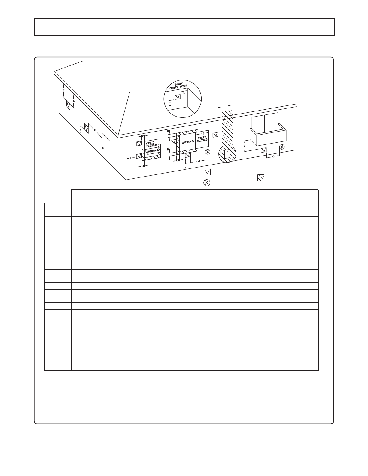
Vent Terminal
Clearance
A=
Above grade, veranda, porch, deck,
or balcony
B=
Window or door that may be opened
C=
Permanently closed window
D=
Vertical clearance to ventilated soffit
located above the terminal within a
horizontal distance of 2 feet from the
center of the terminal
*
E=
Unventilated soffit
*
F=
Outside corner
*
G=
Inside corner
*
H=
Each side of center line extended
above meter/regulator assembly
3' (0.9m) within a height 15' (4.5m)
above meter/regulator assembly
I=
Service regulator vent outlet
3' (0.9m)
J=
Nonmechanical air supply inlet or
combustion air inlet to any other
appliance
K=
Mechanical air supply inlet
3' above if within
10' [6' (1.8m)]
L=
Above paved sidewalk or paved
driveway located on public property
Under veranda, porch, deck, or
balcony
* [7' (2.1mm***)]
M=
[ ] = indicates clearances required in Canada
*Maintain clearances in accordance with local installation codes and the requirements of the gas supplier
***A vent shall not terminate directly above a sidewalk or paved driveway that is located between two
single family dwellings and serves both dwellings.
****Permitted only if veranda,porch,deck,or balcony is fully open on a minimum of two sides beneath the floor.
* [12" (300mm)****]
*
12" [12" (300mm)]
4’ (1.2m) below or to the side of
opening, or 1’ (0.3m)above opening
[36" (900mm)]
Air Supply Inlet
Area Where Terminal
is Not Permitted
Indoor Combustion Air
*
*
*
*
3' (0.9m) within a height 15' (4.5m)
above meter/regulator assembly
3' (0.9m)
3' above if within
10' [6' (1.8m)]
* [7' (2.1mm***)]
* [12" (300mm)****]
*
12" [12" (300mm)]
12" [36" (900mm)]
4’ below or to the side of
opening, or 1’ above opening
[36" (900mm)]
12" [36" (900mm)]
Outdoor Combustion Air
(Direct Vent)
Clearance Requirements from Vent Terminations to Building Openings
* All clearance requirements are in accordance with ANSI Z21.10.3 and the National Fuel Gas Code,
ANSI Z223.1 and in Canada, in accordance with NSCNGPIC.
9
Installation
7.
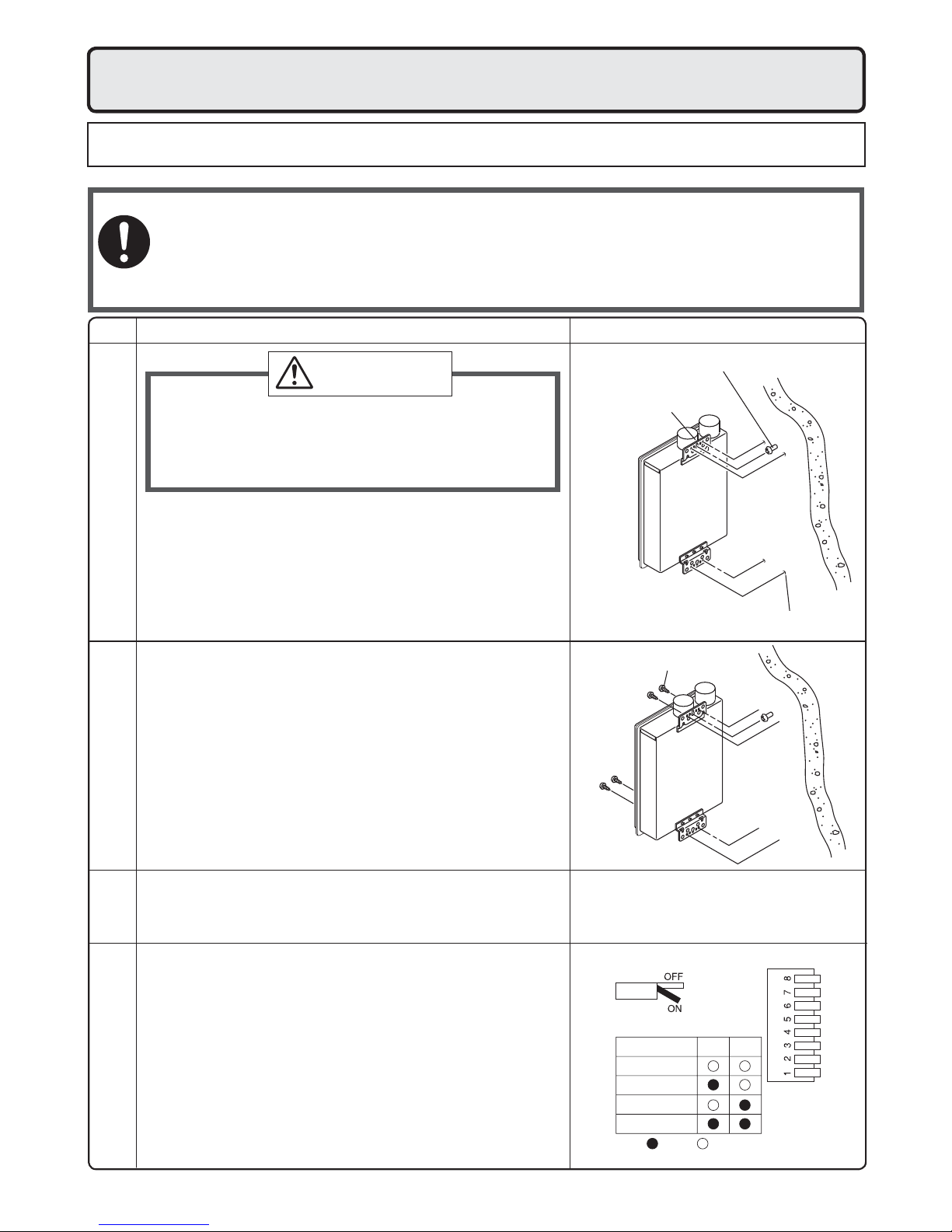
Securing to the wall
• The weight of the device will be applied to the wall. If the strength of the wall is not suf cient, reinforcement must be done to prevent the transfer of vibration.
• Do not drop or apply unnecessary force to the device when installing. Internal parts may
Be sure to do
be damaged and may become highly dangerous.
• Install the unit on a vertical wall and ensure that it is level.
Item
• When installing with bare hands, take caution to
not in ict injury.
• Be careful not to hit electrical wiring, gas, or water
piping while drilling holes.
1. Drill a single screw hole, making sure to hit a stud.
2. Insert and tighten the screw and hang the unit by
Locating Screw Holes
Mounting
the upper wall mounting bracket.
3. Determine the positions for the remaining four screws
(two for the top bracket and two for the bottom), and
remove the unit.
4. Drill holes for the remaining four screws.
5. Hang the unit again by the rst screw, and then
insert and tighten the remaining four screws.
6. Take waterproo ng measures so that water does
not enter the building from screws mounting the
device.
IllustrationCheck
Location of Screw Hole
CAUTION
Mounting Bracket
(upper)
Locating Screw Holes
Tapping Screw
• Make sure the unit is installed securely so that it will
not fall or move due to vibrations or earthquakes.
Structure
• Adjust the dip switches as illustrated in the table to
the right if this water heater is installed at an altitude
of 2000 ft. (610m) or higher.
• Disconnect power to the water heater before changing the dip switches. Failure to perform this step will
result in a "73" code displayed on the remote controller and a cease in operation. If this occurs, disconnect, then reconnect power to the water heater to
Above 2,000 ft.
reset the system.
Note : Please refer to page 29 for the location of the
Installations at Elevations
dip switch bank.
10
* Do not change any other dipswitches.
* High elevation adjustment.
65
Standard
2,000 ft (610m)
4,000 ft (1,220m)
6,000 ft (1,830m)
ON= OFF=
Filling the condensate trap with water
30 oz.
850ml
The condensate trap can be lled before connecting the vent pipe.
Filling the condensate trap before vent pipe installation.
Prior to initial start up, make sure that you ll the condensate trap with water.
DANGER
Please follow one of the procedures described below to ensure that the condensate trap is lled with water.
1) Fill the condensate trap by pouring approx. 30 oz.(850ml) of water into the exhaust accessory on the top
of the appliance as illustrated below.
This is to prevent dangerous exhaust gases from entering the building.
Failure to ll the condensate trap could result in severe personal injury or death.
Intake
Exhaust
Or, if the vent pipe has already been installed:
2) After installing the drain pipe, make sure that the area around the appliance is well ventilated; open a
window or a door if necessary.
Then, operate the unit and verify that condensate is coming out of the drain pipe.
(During normal use of the water heater, condensate will begin to discharge from the drain pipe within
15 minutes of use. However, depending on the season and/or installation site conditions, it may take longer.)
Note: The condensate discharged from the water heater has a pH level of approximately 2-3.
If required by local code, the condensate must be neutralized prior to disposal into the sewer system.
Refer to pages 22-23 for additional details.
11
8.
Be sure to do
Vent Pipe Installation
(Indoor Installation Only)
WARNING
CARBON MONOXIDE POISONING
Follow all vent system requirements in accordance with relevant local or state regulation,
or, in the absence of local or state code, in the U.S. to the National Fuel Gas Code ANSI
Z233.1/NFPA 54 – latest edition, and in Canada, in accordance with NSCNGPI.
General Requirements
• Under normal conditions, this appliance will
not produce an exhaust flue temperature
in excess of 149°F (65°C) and schedule 40
PVC pipe may be used as the vent material.
If required by local code, schedule 40 or 80
CPVC may also be used on this appliance.
Refer to page 13 for additional requirements.
• Make sure the vent system is gas tight and
will not leak.
• Support the vent pipe with hangers at regular
intervals as speci ed by these instructions or
the instructions of the vent manufacturer.
• Do not common vent or connect more than
one appliance to this venting system.
•
The total vent length including horizontal & vertical
vent runs should be no less than 3' (0.9m).
• Do not store hazardous or flammable substances near the vent termination and check
that the termination is not blocked in any way.
• Steam or condensed water may come out
from the vent termination. Select the location
for the termination so as to prevent injury or
property damage.
• If snow is expected to accumulate, take care
the end of the pipe is not covered with snow
or hit by falling lumps of snow.
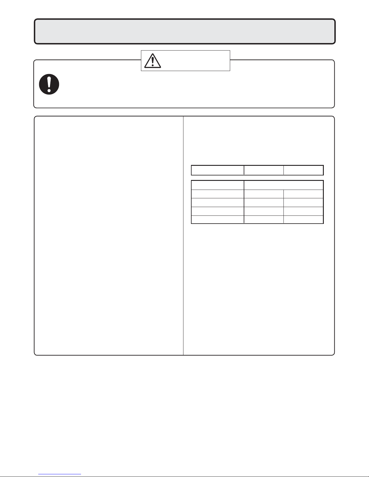
Maximum Vent Lengths
• This appliance has been designed to be vented
with either 3" (75mm) or 4" (100mm) PVC or
CPVC pipe.
Do not exceed the following maximum vent lengths:
Pipe diameter 3" (75mm)4" (100mm)
No. of Elbows
4 35' (10.8m) 35' (10.8m)
3 41' (12.6m) 41' (12.6m)
2 47 (14.4m) 47 (14.4m)
1 53' (16.2m) 53' (16.2m)
* Not including the termination
• Maintain the same vent pipe diameter from the
heater ue to the vent termination. The exhaust
and intake pipes must be the same vent pipe
diameter.
Clearances
PVC or CPVC has been approved for use on this
appliance with zero clearance to combustibles.
Max. Straight Vent Length*
12
 Loading...