

Page 1

Noritsu Quick Service System
Distributed by: minilablaser.com
QSS-32 series
Installation Manual
This manual is for the following machines.
• QSS-3201 Digital
• QSS-3201SM Digital
• QSS-3202 Digital
• QSS-3202SM Digital
• QSS-3203 Digital
• QSS-3203SM Digital
• QSS-3211 Digital
• QSS-3211SM Digital
• QSS-3212 Digital
• QSS-3212SM Digital
• QSS-3213 Digital
• QSS-3213SM Digital
• QSS-3202 PRO Digital Printer
• QSS-3202SM PRO Digital Printer
• QSS-3203 PRO Digital Printer
• QSS-3203SM PRO Digital Printer
• Do not allow any people other than the service personnel to work. It may cause them electric shock, burn and injury.
[for service personnel only]
Page 2

Distributed by: minilablaser.com
Page 3
Notes to service personnel
Distributed by: minilablaser.com
Be sure to read this manual carefully to gain a thorough understanding of the correct procedures before servicing the
machine.
When some of the mounting screws are used in the angle brackets that secure parts of the machine to the packing materials,
they are meant to be re-used when assembling the machine. All screws that are meant to be re-used in this way are described
in the manual.
Any screws that are not designated for re-use in the manual are not necessary for assembly. There is no need to replace the
screws used in the packing materials mentioned in this manual after you have removed them.
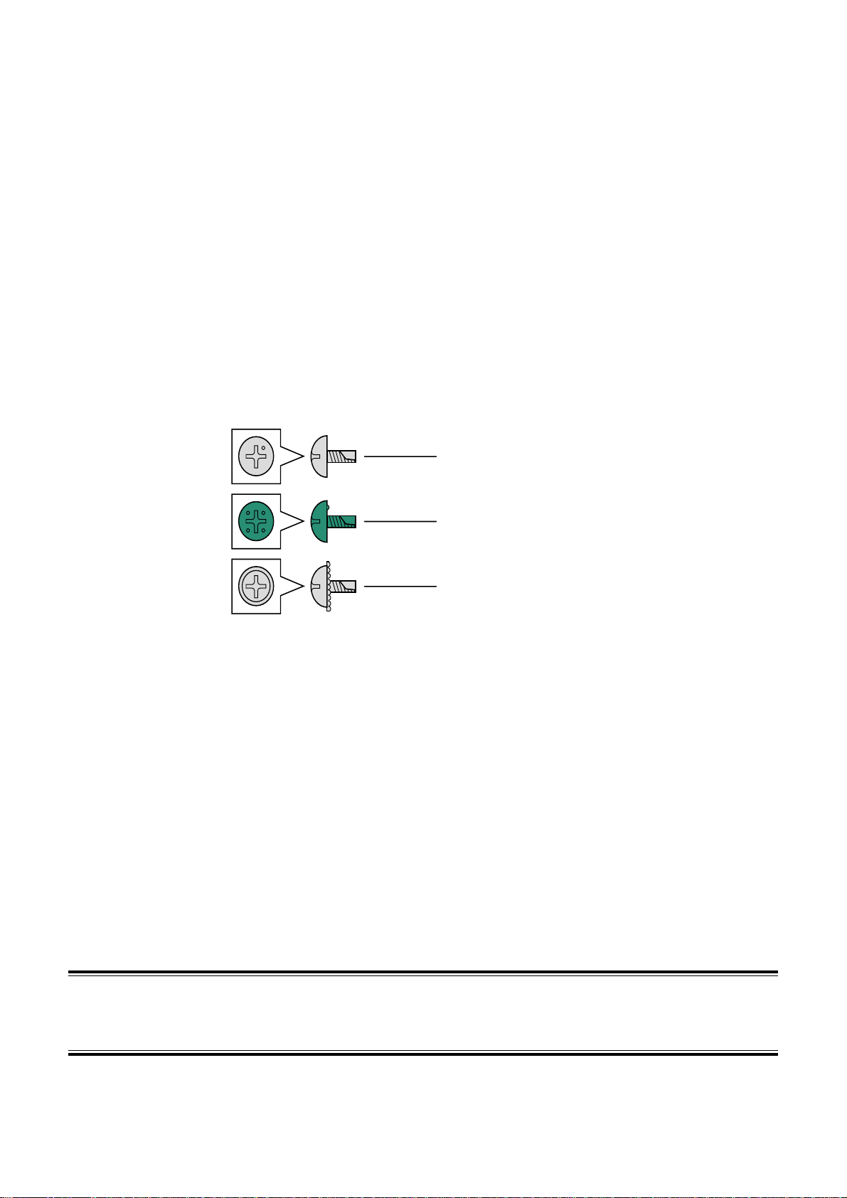
The printer processor may use tapping truss head screws, spike truss head screws and washer head screws.
When attaching the screws once removed, make sure they are on their original positions.
These screws are used for the place where grounding is required.
Tapping truss head screw
Spike truss head screw (green)
Washer head screw (for ground)
SCREW
! It is prohibited to show, provide, lend or transfer this manual to the others except the service personnel.
! The contents of this manual are subject to change without notice.
! Illustrations in this manual may vary depending on the model or manufacturing lot.
Page 4

Microsoft, MS-DOS and Windows are registered trademarks of Microsoft Corporation in the United States and/or other
Distributed by: minilablaser.com
countries.
"UNLHA(32).DLL" is Mr. Micco's free software.
DIGITAL ICE is a trademark of Kodak.
Memory Stick is a trademark of Sony Corporation.
™
MultiMediaCard
is a trademark of Infineon Technologies AG company in Germany and licensed to MMCA (MultiMediaCard
Association).
This software is based in part on the work of the Independent JPEG Group.
Other product and company names mentioned here in may be the trademarks of their respective owners. Symbols of
trademarks,
™
and ®, are not added.
Page 5
Description of warning (signal words)
Distributed by: minilablaser.com
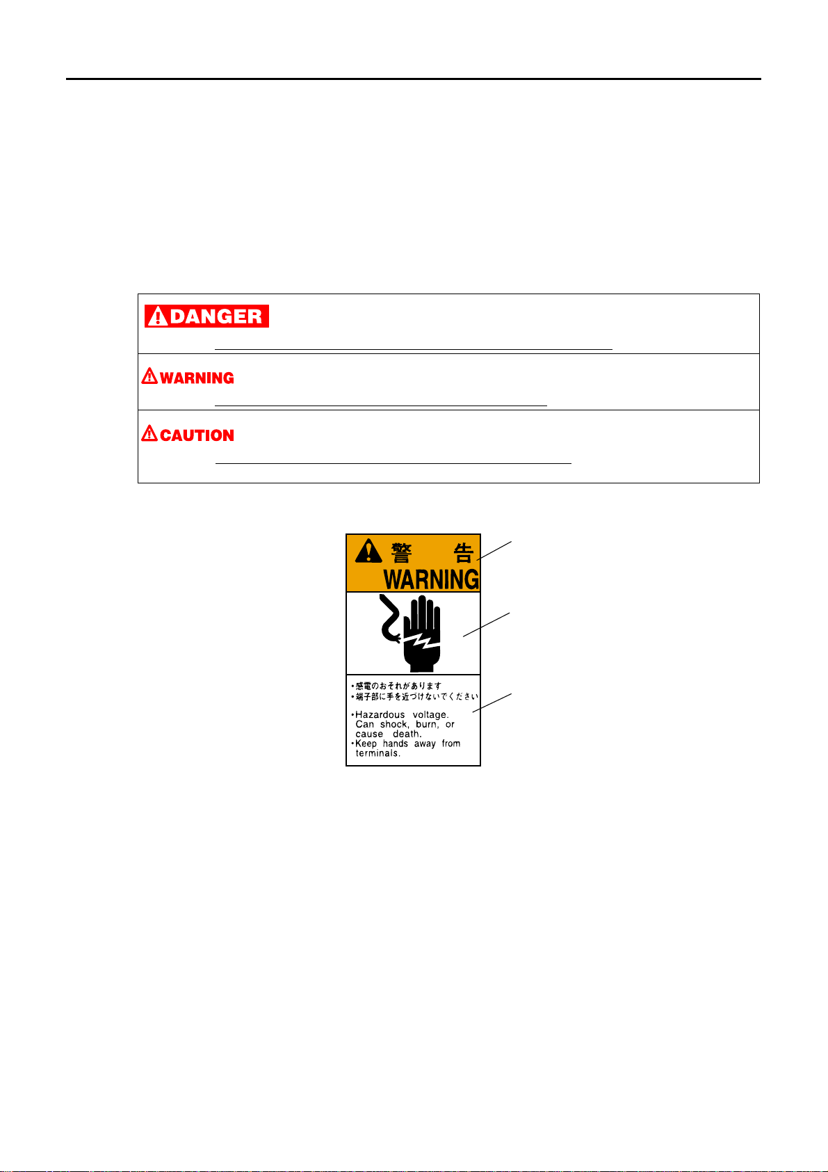
• Signal words identify the level of injuries that can potentially occur.
• The signal words used in this manual and found on labels, DANGER, WARNING and CAUTION, are assigned
according to the level of potential risk.
• Warning labels are located at or near the part of the machine that pose the indicated danger. If ignored, death or serious
injury occurs, or the machine breaks down. Be sure to follow the indications in the manuals or on the warning labels.
• The warnings include a signal word, the type and extent of the danger, and information to avoid danger.
• Carefully read and follow the warnings included in this manual and on the warning labels before operating the machine.
This indicates situations that if not immediately avoided could result in serious injury or death.
This indicates situations that if not avoided could result in serious injury or death.
This indicates situations that if not avoided could result in non-life threatening injury
which may cause damage to physical property.
Example of warning label
Warning (signal word)
Symbol mark (warning
indication)
Warning text (warning
indication)
. It is also used to indicate situations
SIGNALWORD
iii
Page 6

System configuration
Distributed by: minilablaser.com
The machine configurations of the systems are as follows.
System Scanner Control Station Laser Printer Paper Processor
QSS-3201 Digital S-2/S-3/S-4 CS-1 LP-1700 PP-1213
QSS-3201SM Digital S-2/S-3/S-4 CS-1 LP-1700 PP-1213SM
QSS-3202 Digital S-2/S-3/S-4 CS-1 LP-1700 PP-1213
QSS-3202SM Digital S-2/S-3/S-4 CS-1 LP-1700 PP-1213SM
QSS-3203 Digital S-2/S-3/S-4 CS-1 LP-1700 PP-1217
QSS-3203SM Digital S-2/S-3/S-4 CS-1 LP-1700 PP-1217SM
QSS-3211 Digital S-2/S-3/S-4 CS-1 LP-1700 PP-1213
QSS-3211SM Digital S-2/S-3/S-4 CS-1 LP-1700 PP-1213SM
QSS-3212 Digital S-2/S-3/S-4 CS-1 LP-1700 PP-1213
QSS-3212SM Digital S-2/S-3/S-4 CS-1 LP-1700 PP-1213SM
QSS-3213 Digital S-2/S-3/S-4 CS-1 LP-1700 PP-1217
QSS-3213SM Digital S-2/S-3/S-4 CS-1 LP-1700 PP-1217SM
System Control Station Laser Printer Paper Processor
QSS-3202 PRO Digital Printer CS-1 LP-1700 PP-1213
QSS-3202SM PRO Digital Printer CS-1 LP-1700 PP-1213SM
QSS-3203 PRO Digital Printer CS-1 LP-1700 PP-1217
QSS-3203SM PRO Digital Printer CS-1 LP-1700 PP-1217SM
iv
Page 7
Precautions for handling the optical fiber cable and LVDS
Distributed by: minilablaser.com
cable
The machine has sections in which the optical fiber cables and the LVDS cables are used.
Before handling the optical fiber cable and the LVDS cable, be sure to read the following precautions thoroughly, then start
work properly.
Precautions when handling the optical fiber cable
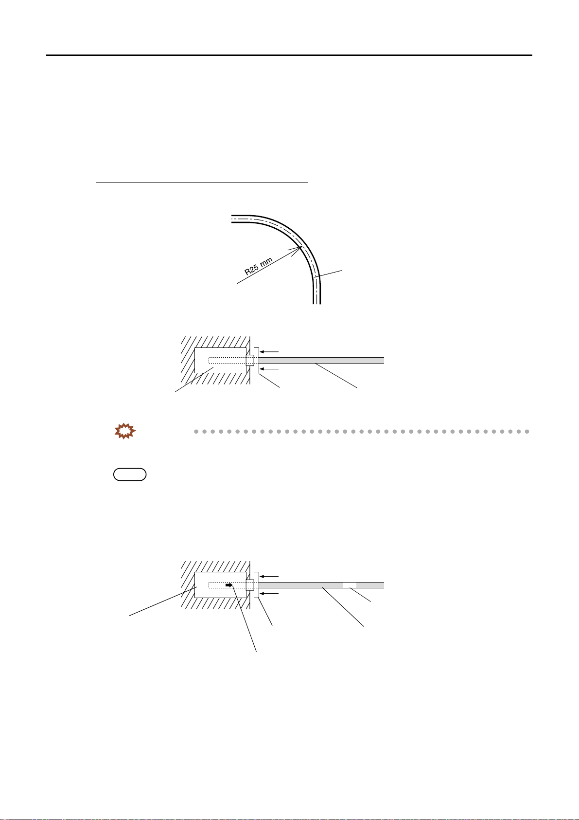
• Do not bend the optical fiber cable by R25 mm or less. The cable may break. Wire the cable with a bending radius of at
least R50 mm. When wiring the cable, do not use force. Do not secure the cable forcibly with mini-bands or clamps.
Optical fiber cable
G051006
• When the optical fiber cable is to be removed from the PCB, pull the cable straight out while pressing part A in the
direction indicated by the arrow. When the cable is to be connected, push it straight as far as it will go.
Connector on the PCB
Optical fiber cablePart A
G051007
IMPORTANT
• If pulling the optical fiber cable out forcibly without pressing part A, the sheath of the cable is broken and
a part of the sheath remains in the connector, resulting in the communication error.
NOTE
• Use the optical fiber cable pushing bar to pull it out when it is hard to reach part A.
The optical fiber cable pushing bar is a service personnel tool.
• Since the optical fiber cable is provided with IN side and OUT side, be careful to connect them correctly. If part A of the
connector on the PCB is white, the cable end should indicate OUT. If part A is black, the cable end should indicate IN.
The OUT cable end is marked using a white tape. There is no marking on the IN cable end.
OUT
Marking on the cable
Connector on the PCB
The arrow on the connector indicates the direction to the connector.
Optical fiber cablePart A (White)
G051008
v
Page 8
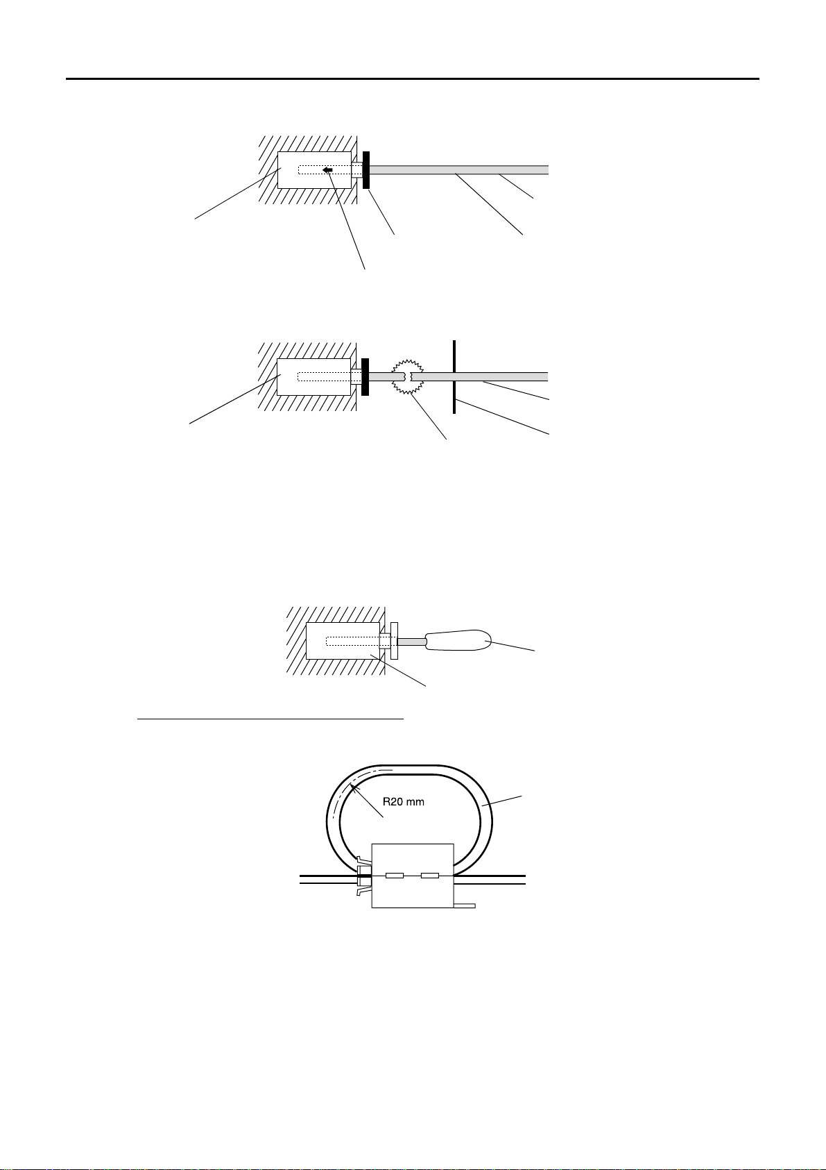
IN
Distributed by: minilablaser.com
No marking on the cable
Connector on the PCB
The arrow on the connector indicates the direction to the PCB.
Optical fiber cablePart A (Black)
G051009
• If the optical fiber cable is damaged, it cannot be reused even after the damaged part has been cut off. A communication
error occurs.
Optical fiber cable
Connector on the PCB
Damaged part
Do not reuse this cable even if the
damaged part has been cut off.
G051010
• Do not place an excessive load on the optical fiber cable or let a hard or heavy object fall on it.
• Do not damage the sheath of the optical fiber cable. A dent or flaw on the sheath, however small, means the optical fiber
cable cannot be used.
• Never touch the end face of the optical fiber cable with bare hands. Communication will not be possible if oil or dust
adheres to the cable end, or if the cable end is scratched.
• The connector guard unit must be inserted into an unused connector for the optical fiber cable. This prevents dust from
entering inside the connector. And also prevents malfunction due to outside light.
Connector guard unit
Unused connector
G050366
Precautions when handling the LVDS cable
• Do not bend the LVDS cable by radius 20 mm or less. The cable may break. Wire the cable with a bending radius of at
least R50 mm. When inserting, removing, attaching the ferrite core, or wiring the cable, do not use force.
LVDS cable
G063561
vi
Page 9
Laser Precautions
Distributed by: minilablaser.com
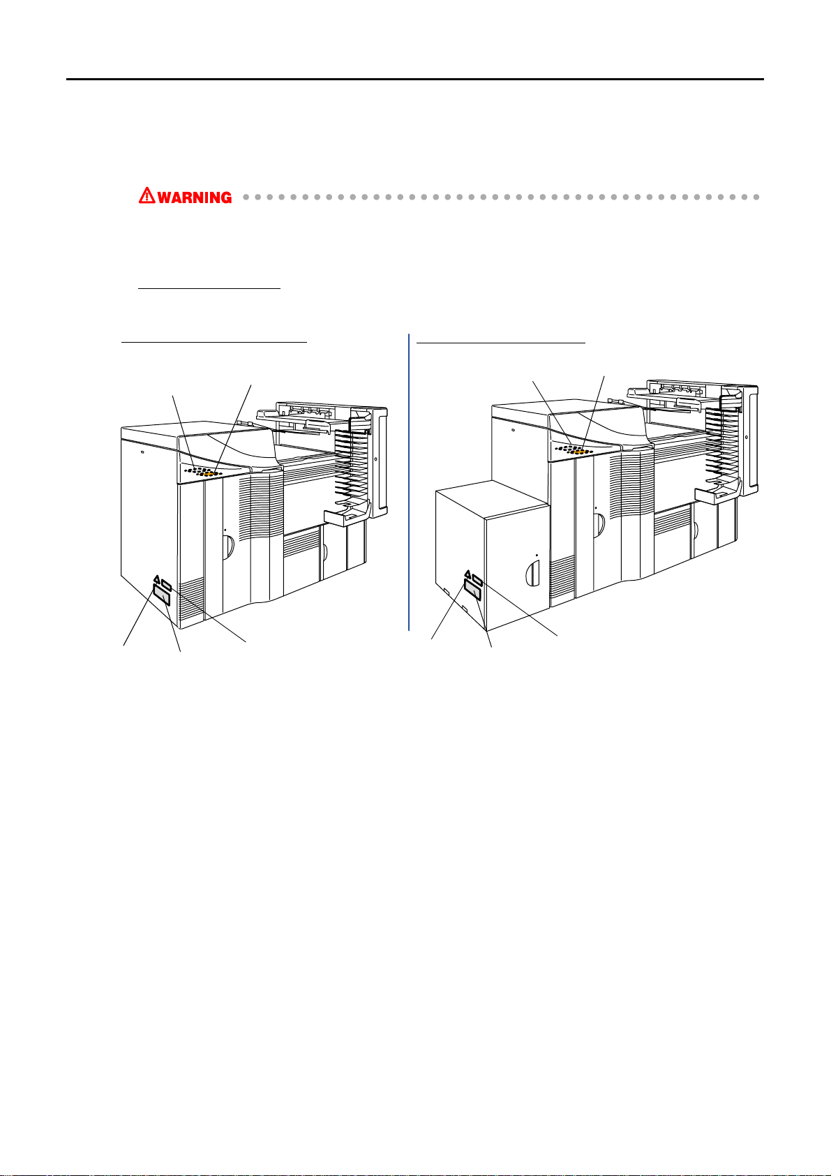
The laser machinery is built into the printer.
• Follow the instructions to avoid exposing your eyes to laser radiation.
• Do not remove any parts except specified ones.
• Do not perform printing operations while the safety device is released.
Location of laser labels
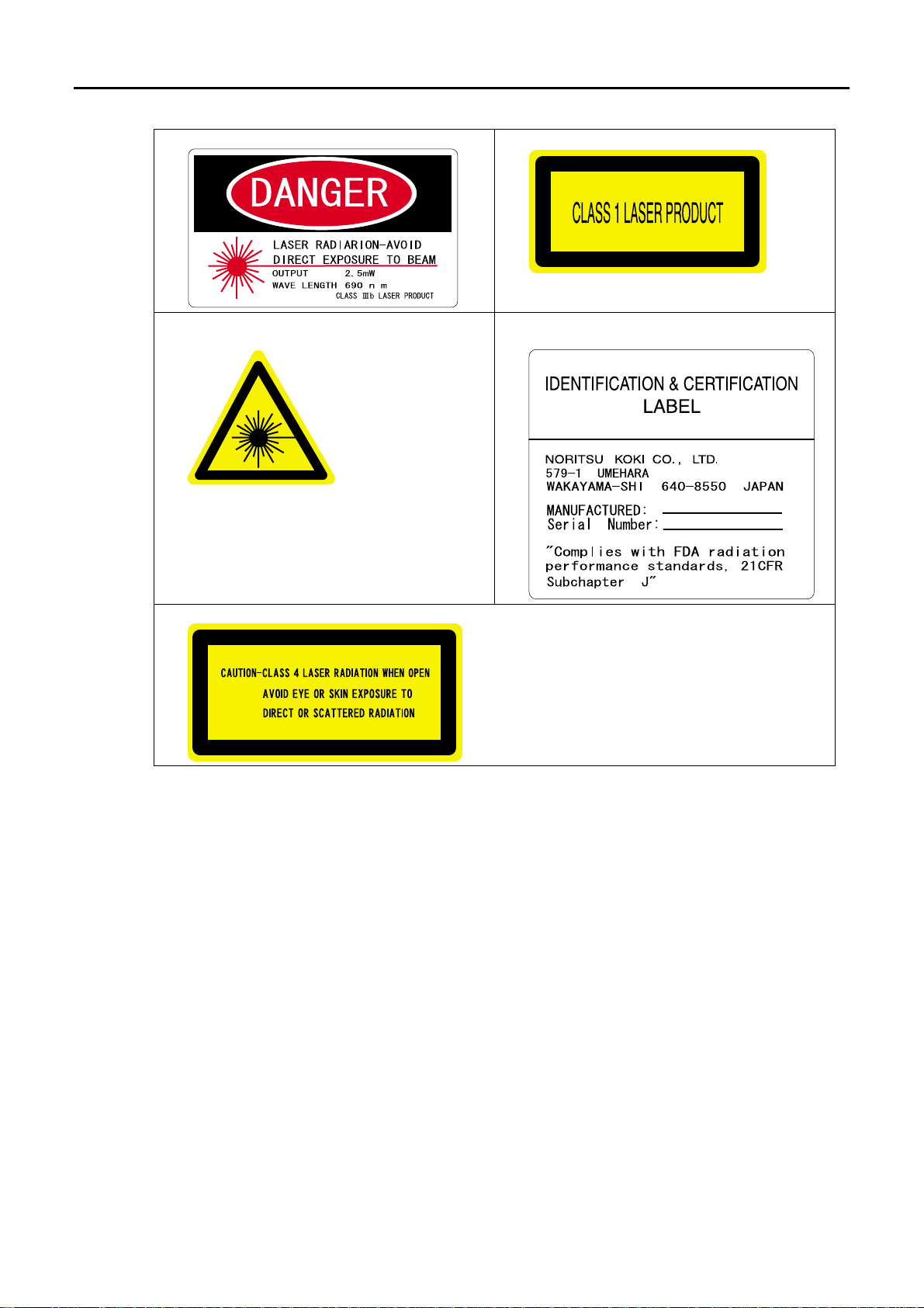
The labels for the laser precautions are placed on this machine.
Do not remove those labels.
When the triple magazine is not equipped
When the triple magazine is equipped
5
3
4
1
2
3
5
2
4
1
G068048
vii
Page 10
12
Distributed by: minilablaser.com
3
5
4
viii
Page 11
Precautions against LED
Distributed by: minilablaser.com
Precaution only when the scanner is equipped.
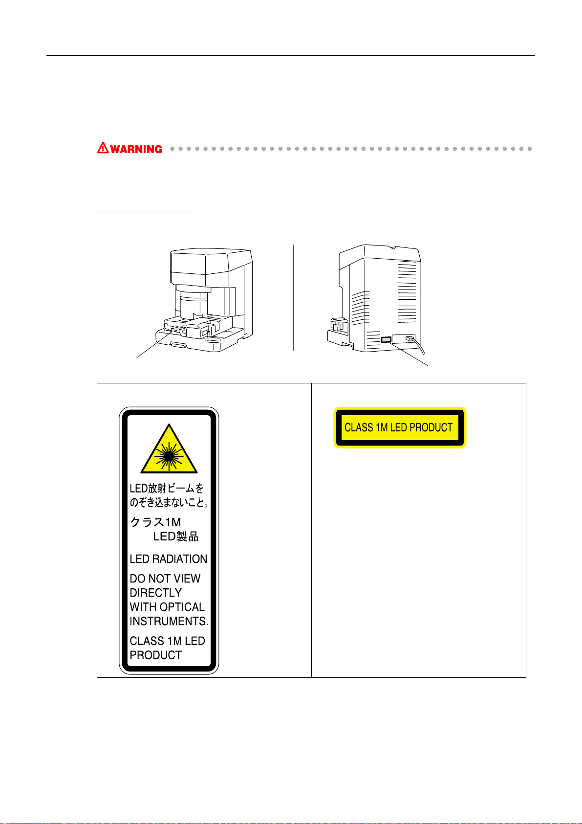
The LED machinery is built into the scanner.
• Follow the instructions to avoid exposing your eyes to LED radiation.
• Do not remove any parts except specified ones.
• Do not take a direct look with optical instruments.
Location of LED labels
The labels for the LED precautions are placed on this machine.
Do not remove those labels.
1
1
2
2
G070355
ix
Page 12

TABLE OF CONTENTS
Distributed by: minilablaser.com
Notes to service personnel
Description of warning (signal words) .................................................................................................... iii
System configuration .............................................................................................................................iv
Precautions for handling the optical fiber cable and LVDS cable ...........................................................v
Laser Precautions ................................................................................................................................. vii
Precautions against LED .......................................................................................................................ix
1 Before installing.............................................................................................................................. 1
1.1 Place for installation............................................................................................................................................... 1
1.2 Countermeasure for the static electricity when replacing and maintaining the electrical parts............................. 1
1.3 Necessary tools....................................................................................................................................................... 2
1.4 Description for each specification.......................................................................................................................... 2
2 Work flow ....................................................................................................................................... 3
2.1 Work flow [N] ........................................................................................................................................................ 3
2.2 Work flow [SM] ..................................................................................................................................................... 4
3 Removing the packing angle brackets ........................................................................................... 7
3.1 Printer section......................................................................................................................................................... 7
3.2 Paper processor section ........................................................................................................................................ 14
3.2.1 Paper processor section [N].................................................................................................................................. 14
3.2.2 Paper processor section [SM]............................................................................................................................... 16
3.3 Desk section ......................................................................................................................................................... 17
3.4 Scanner section..................................................................................................................................................... 19
4 Installing the component parts and units...................................................................................... 22
4.1 Printer section....................................................................................................................................................... 22
4.2 Paper Processor .................................................................................................................................................... 25
4.2.1 Paper processor section [N].................................................................................................................................. 25
4.2.2 Paper processor section [SM]............................................................................................................................... 35
4.3 Desk section ......................................................................................................................................................... 43
4.4 Scanner section..................................................................................................................................................... 47
5 Installing the machine and adjusting the level.............................................................................. 53
5.1 Adjusting the level of paper processor section..................................................................................................... 53
5.2 Connecting the printer and the paper processor and adjusting the level .............................................................. 58
5.3 Connecting the desk section and the printer section (power cable) ..................................................................... 65
5.4 Measuring the resistance ...................................................................................................................................... 66
5.5 Connecting the desk section and the printer section (signal cable)...................................................................... 68
5.6 Connecting the scanner section and the desk section (signal cable) .................................................................... 70
6 Connecting the power supply ....................................................................................................... 72
6.1 Connecting the power supply............................................................................................................................... 72
7 Filling the tanks with processing and replenishment solutions..................................................... 74
7.1 Filling the tanks with processing and replenishment solutions [N] ..................................................................... 74
7.2 Filling the tanks with processing solutions and attaching the replenishment packages [SM] ............................. 77
8 Miscellaneous work ...................................................................................................................... 82
8.1 Storing the enclosed floppy disks and CD-ROMs ............................................................................................... 82
8.2 Attaching the float switch check date entry sticker.............................................................................................. 82
x
Page 13

8.3 Writing down the date of installation on the battery replacement label............................................................... 82
Distributed by: minilablaser.com
8.4 Attaching the labels.............................................................................................................................................. 83
8.4.1 System label ......................................................................................................................................................... 83
8.4.2 Labels for NORITSU only ................................................................................................................................... 84
8.5 Attaching the Long Length Print Tray ................................................................................................................. 86
8.6 Setting up the machine ......................................................................................................................................... 87
9 Installing the optional triple magazine .......................................................................................... 88
10 Check sheet for removing the packing angle brackets and the packing materials ...................... 95
xi
Page 14

This page is intentionally blank.
Distributed by: minilablaser.com
Page 15
1 Before installing
Distributed by: minilablaser.com
1.1 Place for installation
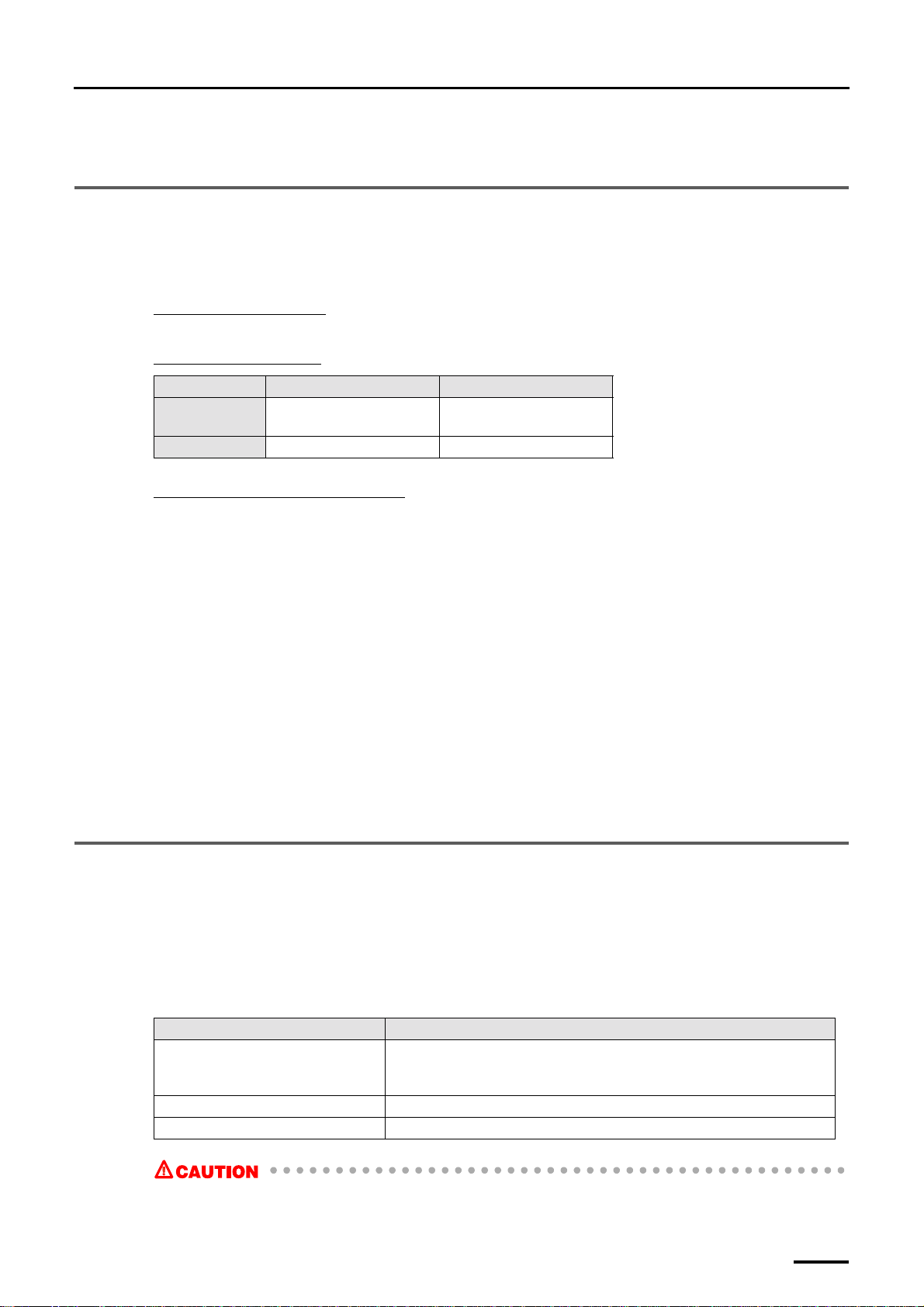
!!!! Mass applied to a jack bolt or a castor
The mass applied to each jackbolt/castor in the printer, paper processor, and desk (including scanner) is listed below.
Printer section (LP-1700)
Approx. 72 kg
Paper processor section
Specification PP-1213 PP-1217
Normal
specification
SM specification Approx. 78.8 kg Approx. 80.5 kg
Desk (CS-1) +Scanner (S-2/S-3/S-4)
Approx. 35.8 kg (for S-2/S-3)
Approx. 34.9 kg (for S-4)
Approx. 92.6 kg Approx. 92.5 kg
1 Before installing
!!!! Floor condition for installation
• The floor should have strength which the usual vibration, such as walking a person or opening/closing a door, is not
affected to the machine.
As a guide, the strength is the extent to which a standing person on the floor does not feel a vibration when a 20-litter
plastic tank which contains 10 litters of water is fallen at intervals of 20 to 30 cm from the person.
If this condition is satisfied, the floor made of concrete or linoleum, or on which thin carpet or plastic tiles are spread is
okay.
However, the floor made of wood and under which is hollow, or on which thick carpet is spread is not suitable.
2
• The floor is even and no vibration is given to the machine. Vibration should be 3 m/s
direction on the installation place.
(0.3 G) or less in each
!!!! Power requirement for installation
• Make sure that the power supply for ground resistence of 100 Ω or less is prepared.
1.2 Countermeasure for the static electricity when replacing and maintaining the electrical parts
If an electronically charged human body touches electronic parts like PCBs, it may adversely affect the electronic parts.
When handling the electronic parts, be sure to use static-dissipative tools to prevent the electrical parts from being damaged
due to static electricity.
Also use the static-dissipative tools for maintenance of the digital units or engines.
Static-dissipative tool
Name Remarks
Portable Static-Dissipative Field
Service Kit
Static-Dissipative conductive gloves Use this to prevent that sebum on your hand adheres when you touch a PCB.
Wrist Strap Use this when checking the electronic parts.
• When using the static-dissipative tool, be sure to turn off the circuit breaker of the unit and the main power
supply, and wait 10 seconds or more to carry out operation.
Use this kit when replacing or installing/removing the electronic parts from the
machine. This kit consists of four items of Static-Dissipative Work Mat, Wrist
Strap, Ground Cord, and Alligator Clips.
1
Page 16
1 Before installing
Distributed by: minilablaser.com
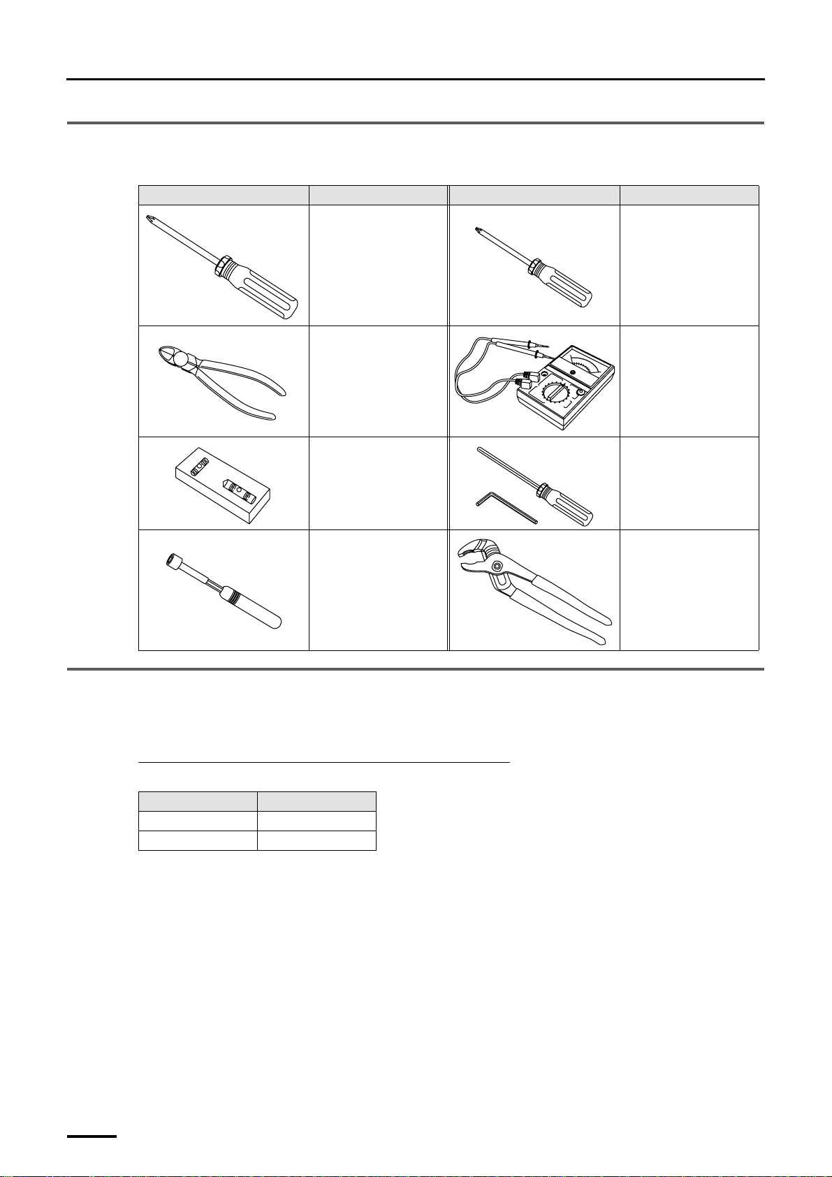
1.3 Necessary tools
Make sure you have prepared these tools before you start working.
Tool Tool name Tool Tool name
Philips blade screwdriver
(large)
Diagonal cutting pliers Voltmeter
Level Hex. wrench
Philips blade screwdriver
(small)
Nut driver Utility pliers
1.4 Description for each specification
This manual describes the installation procedure for all the specifications.
The procedure for each specification may differ.
For the different procedures depending on the specifications
The specification mark is mentioned for the procedure.
Specification Mark
Normal specification [N]
SM specification [SM]
There is no specification mark for the procedure which is same for all the specifications.
2
Page 17

2Work flow
Distributed by: minilablaser.com
Installation work should only be performed by an authorized service personnel.
The work flow varies depending on the specification.
Check the machine specification and refer to each work flow.
• For the normal specification, refer to
☞2.1 Work flow [N].
2Work flow
• For SM specification, refer to
2.1 Work flow [N]
1. Confirmation of component parts
Check that the parts provided are in accordance with the shipping list.
2. Removing the packing angle brackets
(1) Printer section
• Removing the packing angle brackets from magazine deck units B and C
• Removing the packing angle brackets, plates, bolts and washers from the paper supply unit
• Removing the packing angle brackets from the exposure main body unit
• Removing the packing angle brackets from the paper advance section
• Removing the mini-bands from the processor loading unit
• Removing the packing angle brackets and pins from the laser unit
(2) Paper processor section
• Removing the packing angle brackets from the dryer section
• Removing the packing screws from the replenishment unit
(3) Desk section
• Removing the packing angle brackets from the colorimeter
☞2.2 Work flow [SM].
(4) Scanner section
This is for the machine with the scanner.
• Removing the packing angle brackets from the film carrier
3. Installing the component parts and units
(1) Printer section
• Attaching the scratch prevention guide to the paper supply unit
• Attaching the lock levers to the magazine deck unit
• Attaching the ribbon cassette (only when the optional CVP unit is to be equipped)
• Attaching the pressure guide to the exposure advance unit
(2) Paper processor section
• Attaching the roller
• Installing the print conveyor unit
• Attaching the conveyor guide
• Attaching the print receiving tray (large) (only when the optional print accumulation tray is not to be
equipped)
• Installing the print sorter unit
• Attaching the filter cartridges
• Putting the floating balls into the tanks
3
Page 18

2Work flow
Distributed by: minilablaser.com
(3) Desk section
• Installing the display monitor
• Attaching the air filters
• Attaching the calibration plate to the colorimeter unit
• Checking the PC unit power supply
• Attaching the capacity booster
(4) Scanner section
This is for the machine with the scanner.
• Installing the scanner
• Attaching the optional film carrier
• Attaching the optional film cleaner kit
• Attaching the optional film receiving box
4. Installing the machine and adjusting the level
• Adjusting the level of the paper processor
• Connecting the printer and the paper processor and adjusting the level
• Connecting the desk section and the printer section (power cable)
• Measuring the resistance
• Connecting the desk section and the printer section (signal cable)
• Connecting the scanner section and the desk section (signal cable)
5. Connecting the power supply
6. Filling the tanks with processing and replenishment solutions
7. Miscellaneous work
• Writing the date of installation on the battery replacement label
• Putting labels
• Attaching the long length print tray
• Setup of the machine
8. Installing the optional triple magazine
• Removing the packing angle brackets from the triple magazine
• Attaching the lock levers to magazine deck unit A
• Connecting the triple magazine and the printer
2.2 Work flow [SM]
1. Confirmation of component parts
Check that the parts provided are in accordance with the shipping list.
2. Removing the packing angle brackets
(1) Printer section
• Removing the packing angle brackets from magazine deck units B and C
• Removing the packing angle brackets, plates, bolts and washers from the paper supply unit
• Removing the packing angle brackets from the exposure main body unit
4
Page 19

• Removing the packing angle brackets from the paper advance section
Distributed by: minilablaser.com
• Removing the mini-bands from the processor loading unit
• Removing the packing angle brackets and pins from the laser unit
(2) Paper processor section
• Removing the packing angle brackets from the dryer section
• Removing the packing screws from the replenishment unit
(3) Desk section
• Removing the packing angle brackets from the colorimeter
(4) Scanner section
This is for the machine with the scanner.
• Removing the packing angle brackets from the film carrier
3. Installing the component parts and units
(1) Printer section
• Attaching the scratch prevention guide to the paper supply unit
• Attaching the lock levers to the magazine deck unit
• Attaching the ribbon cassette (only when the optional CVP unit is to be equipped)
• Attaching the pressure guide to the exposure advance unit
2Work flow
(2) Paper processor section
• Attaching the roller
• Installing the print conveyor unit
• Attaching the conveyor guide
• Attaching the print receiving tray (large) (only when the optional print accumulation tray is not to be
equipped)
• Installing the print sorter unit
• Attaching the filter cartridges
(3) Desk section
• Installing the display monitor
• Attaching the air filters
• Attaching the calibration plate to the colorimeter unit
• Checking the PC unit power supply
• Attaching the capacity booster
(4) Scanner section
This is for the machine with the scanner.
• Installing the scanner
• Attaching the optional film carrier
• Attaching the optional film cleaner kit
• Attaching the optional film receiving box
4. Installing the machine and adjusting the level
• Adjusting the level of the paper processor
• Connecting the printer and the paper processor and adjusting the level
• Connecting the desk section and the printer section (power cable)
• Measuring the resistance
• Connecting the desk section and the printer section (signal cable)
• Connecting the scanner section and the desk section (signal cable)
5
Page 20

2Work flow
Distributed by: minilablaser.com
5. Connecting the power supply
6. Filling the tanks with processing solutions and attaching the replenishment packages
7. Miscellaneous work
• Writing the date of installation on the battery replacement label
• Putting labels
• Attaching the long length print tray
• Setup of the machine
8. Installing the optional triple magazine
• Removing the packing angle brackets from the triple magazine
• Attaching the lock levers to magazine deck unit A
• Connecting the triple magazine and the printer
6
Page 21
3 Removing the packing angle brackets
Distributed by: minilablaser.com
3 Removing the packing angle brackets
Remove the packing materials, such as packing angle brackets and packing screws from each section.
NOTE
• After removing the packing angle brackets and the packing materials, confirm that they are all removed with the
☞10 Check sheet for removing the packing angle brackets and the packing materials.
3.1 Printer section
Do not use the packing angle brackets and packing screws you have removed from the machine. Only use them when you are
instructed to do so.
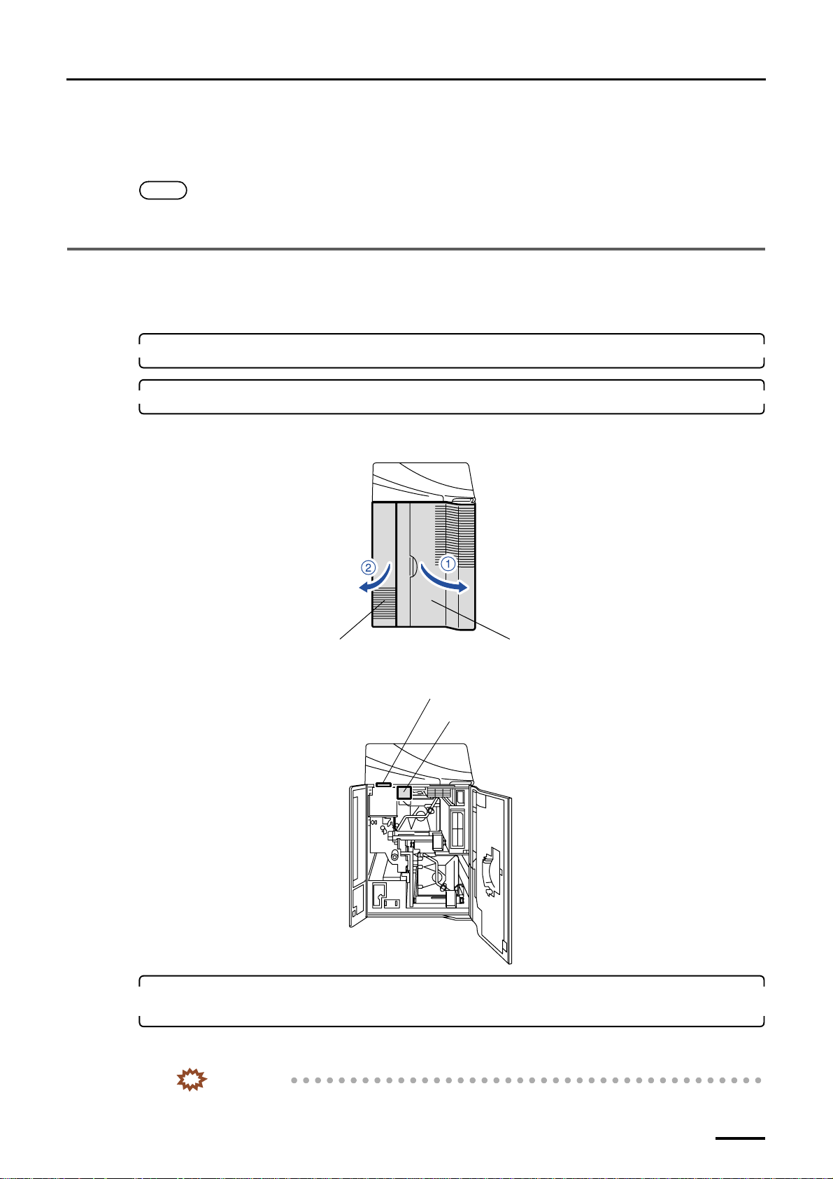
1. Remove all the cardboards, adhesive tapes, ropes and packing materials from the machine.
2. Remove the packing materials from the printer door and paper magazine B.
(1) Open the printer doors.
Printer door 1
Printer door 2
G068871
(2) Remove the two packing materials.
Packing material for the printer door (one piece)
Packing material for paper magazine B (one piece)
G068872
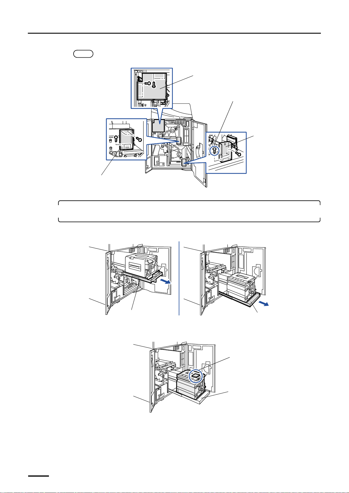
3. Remove the packing angle brackets and plate from magazine deck units B and C. (four
packing screws each)
While the removed fixing angle brackets are not for reuse, the screws must be reattached to their original positions
after the brackets have been removed.
IMPORTANT
• Be sure to reattach the specified screw to its original position. Otherwise, it will cause light leak.
7
Page 22
3 Removing the packing angle brackets
Distributed by: minilablaser.com
NOTE
• When removing the packing angle plate, if you use a long screwdriver, the work will be easier.
Packing angle bracket for
magazine deck unit B
Packing angle plate
Reattach these screws to their original
positions after you remove the packing angle
bracket. (two screws)
Packing angle bracket for
magazine deck unit C
G068873
4. Pull out magazine deck units B and C to remove the packing materials and the two paper
magazines.
(1) Pull out magazine deck units B and C.
Magazine deck unit B
(2) Remove the packing material from magazine deck unit C.
Packing material (one piece)
Magazine deck unit C
G072511
8
Magazine deck unit C
G072512
Page 23
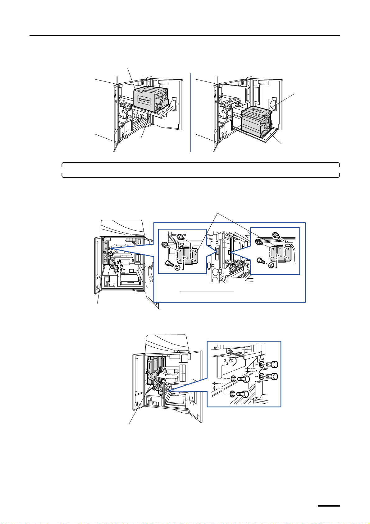
(3) Remove the two paper magazines.
Distributed by: minilablaser.com
Paper magazine
3 Removing the packing angle brackets
Paper magazine
Magazine deck unit B
Magazine deck unit C
5. Remove the packing angle brackets from the paper supply unit.
(1) Remove two packing angle brackets 1. (four packing screws, one packing bolt and one washer for each
bracket)
Packing angle brackets 1
Viewed from the right side
Paper supply unit
(2) Remove the four packing bolts and four washers.
G068875
G068877
Paper supply unit
G068878
9
Page 24
3 Removing the packing angle brackets
Distributed by: minilablaser.com
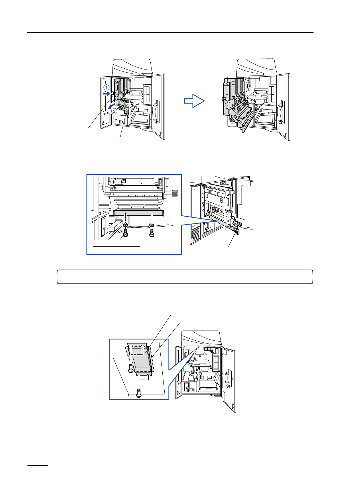
(3) Pull out the paper supply unit while pushing the lock lever to the right.
Lever
Paper supply unit
(4) Remove packing angle bracket 2. (two packing bolts and two washers)
This figure does not have the optional triple magazine.
G068865
Viewed from the left side
Packing angle bracket 2
G068880
(5) Return the paper supply unit to its original position.
6. Remove the packing angle bracket and packing material from the exposure main body unit.
(1) Remove the packing angle bracket. (four packing screws)
(2) Remove the packing material (one piece).
Packing angle bracket
Packing material (one piece)
(3) Close printer doors 1 and 2.
10
G068881
Page 25
3 Removing the packing angle brackets
Distributed by: minilablaser.com
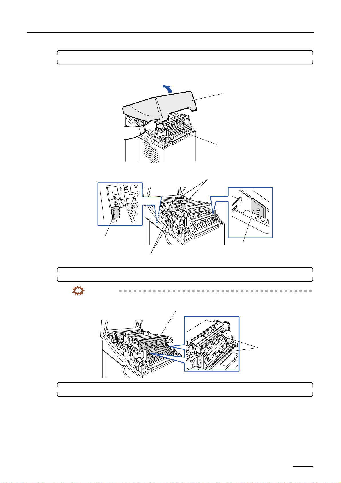
7. Remove the packing materials from the exit paper advance section.
(1) Hold the handle and open the printer top cover slowly.
Printer top cover
Handle
(2) Remove the packing materials (six pieces).
Packing materials (two pieces)
G068884
Packing material
Packing material
Packing materials (two pieces)
8. Cut off the mini-bands on the processor loading unit using a diagonal cutting pliers.
IMPORTANT
• Be careful not to drop the mini-bands into the machine.
Processor loading unit
Mini-bands
9. Remove the packing angle brackets from paper advance unit 2.
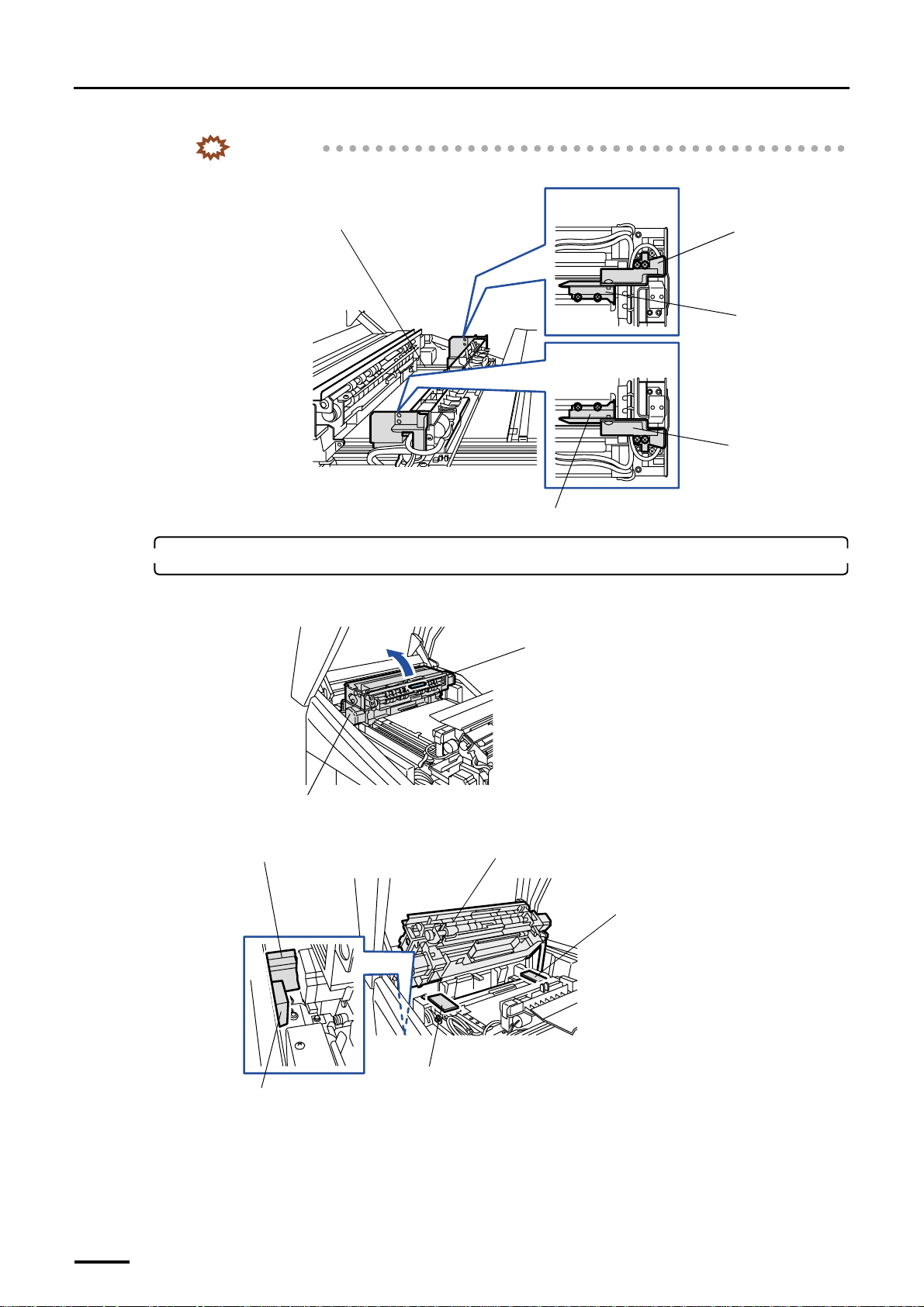
Remove packing angle brackets 2 and 3 on both sides of paper advance unit 2. Each bracket is attached with two
packing screws.
G068885
G068876
11
Page 26
3 Removing the packing angle brackets
Distributed by: minilablaser.com
IMPORTANT
• Be careful not to drop the removed screws into the machine.
Paper Advance Unit 2
Viewed from above
Packing angle
bracket 2
Packing angle
bracket 3
Viewed from above
Packing angle bracket
2
Packing angle bracket 3
G068919
10. Remove the two packing angle brackets and packing materials from paper advance unit 1.
(1) Hold the handle and open paper advance unit 1.
Handle
Paper Advance Unit 1
(2) Remove the four packing materials.
Packing material
Paper Advance Unit 1
Packing material
G071518
Packing material
12
Packing material
G068886
Page 27
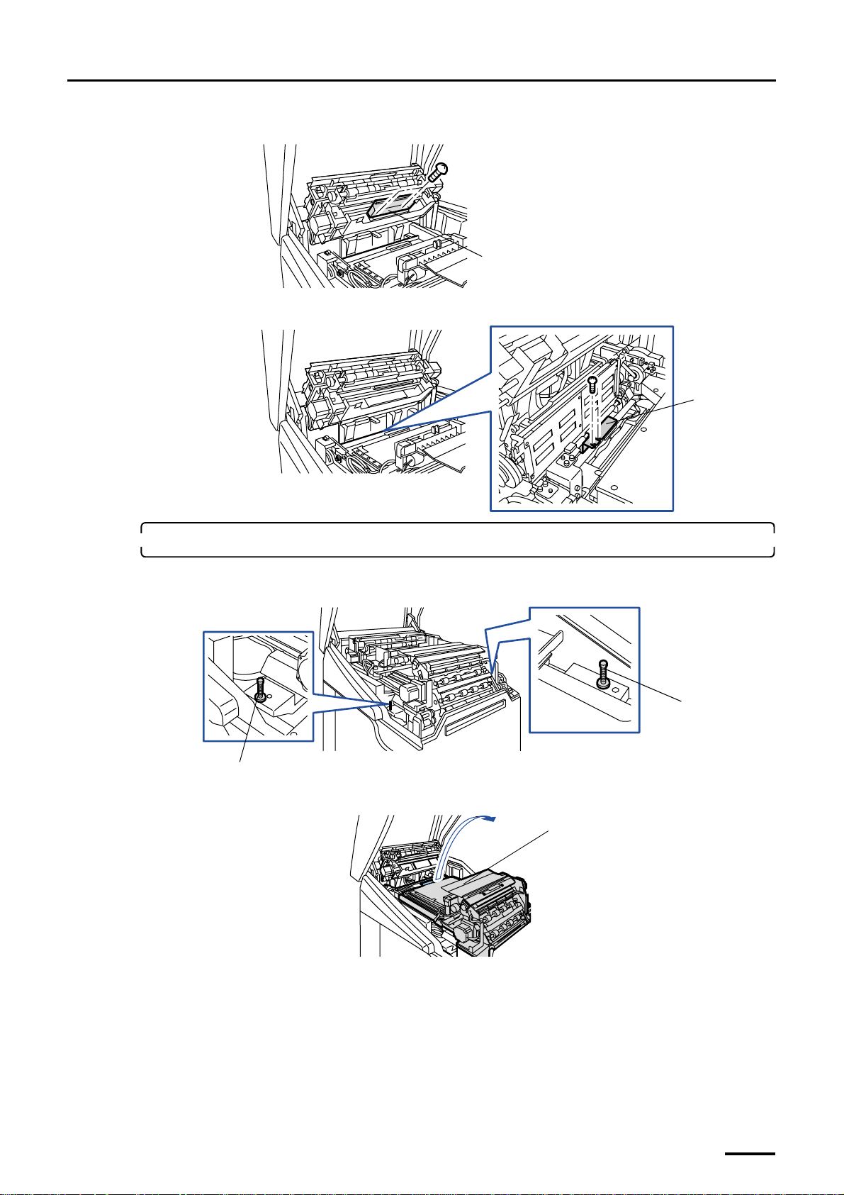
(3) Remove packing angle bracket 1. (two packing screws)
Distributed by: minilablaser.com
Packing angle bracket
(4) Remove packing angle bracket 2. (two packing screws)
3 Removing the packing angle brackets
G068963
Packing angle
bracket
11. Remove the packing angle bracket and packing pins from the laser unit.
(1) Remove the two packing pins.
Packing pin
(2) Open paper advance unit 2.
Paper Advance Unit 2
G073037
Packing pin
G068874
G068911
13
Page 28
3 Removing the packing angle brackets
Distributed by: minilablaser.com
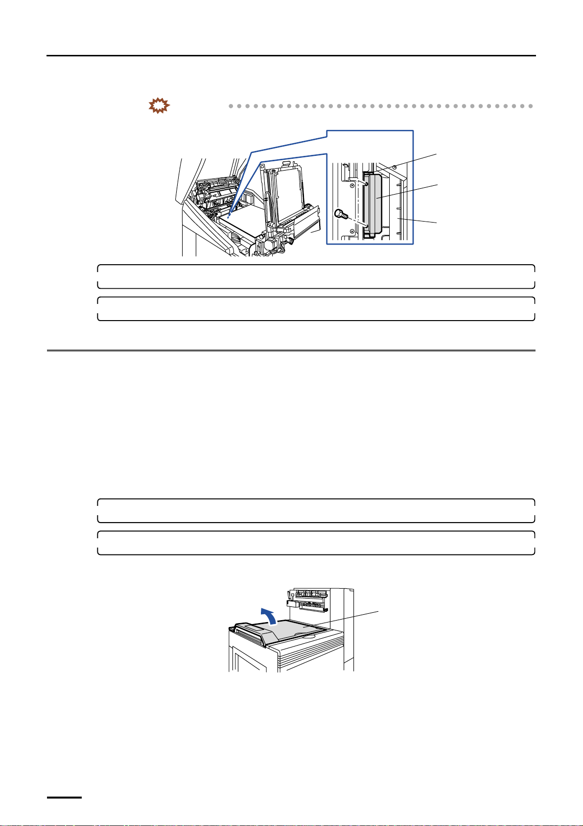
(3) Remove the packing angle bracket and the packing material. (two packing bolts)
IMPORTANT
• Be careful not to drop the removed bolts into the machine.
12. Return paper advance units 1 and 2 to their original positions.
13. Close the printer doors and the printer top cover.
Viewed from above
Packing material
Packing angle
bracket
Laser unit
G068920
This completes removing the packing angle brackets in the printer section.
3.2 Paper processor section
Removing method of the packing angle brackets in the paper processor section varies depending on the specifications. Make
sure the machine specification before start working.
• For the normal specification, refer to
• For SM specification, refer to
☞3.2.2 Paper processor section [SM].
3.2.1 Paper processor section [N]
Do not use the packing angle brackets and packing screws you have removed from the machine. Only use them when you are
instructed to do so.
1. Remove all the cardboards, adhesive tapes, ropes and packing materials from the machine.
2. Remove the packing angle brackets from the dryer section.
(1) Open the processor top cover.
☞3.2.1 Paper processor section [N].
Processor top cover
14
G071516
Page 29
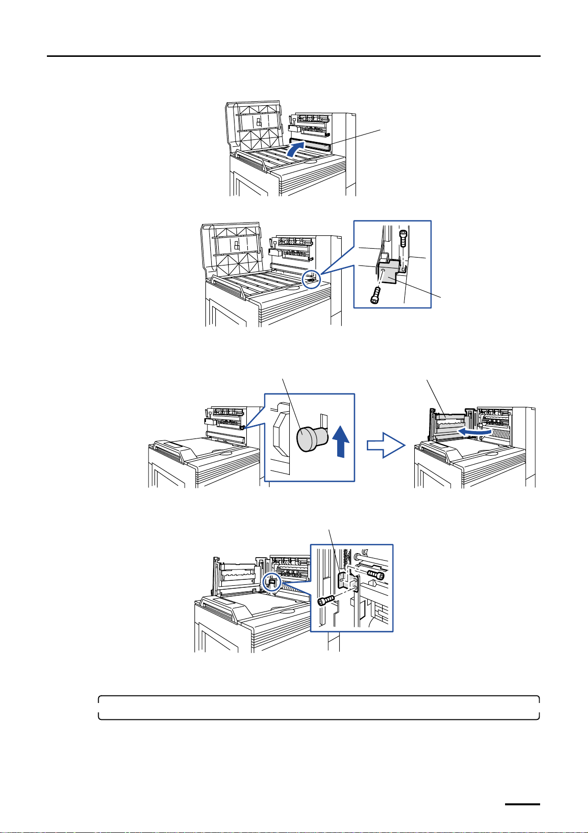
(2) Open the squeegee unit top cover.
Distributed by: minilablaser.com
(3) Remove packing angle bracket 1. (two packing screws)
(4) Close the processor top cover.
3 Removing the packing angle brackets
Squeegee unit top cover
G071514
Packing angle bracket 1
G072510
(5) Raise the lever and open the dryer door.
Lever
(6) Remove packing angle bracket 2. (three packing screws)
Packing angle bracket 2
Dryer door
G068887
(7) Close the dryer door.
(8) Close the squeegee unit top cover.
3. Remove the packing screw from the replenishment unit.
(1) Open the processor doors.
G068888
15
Page 30
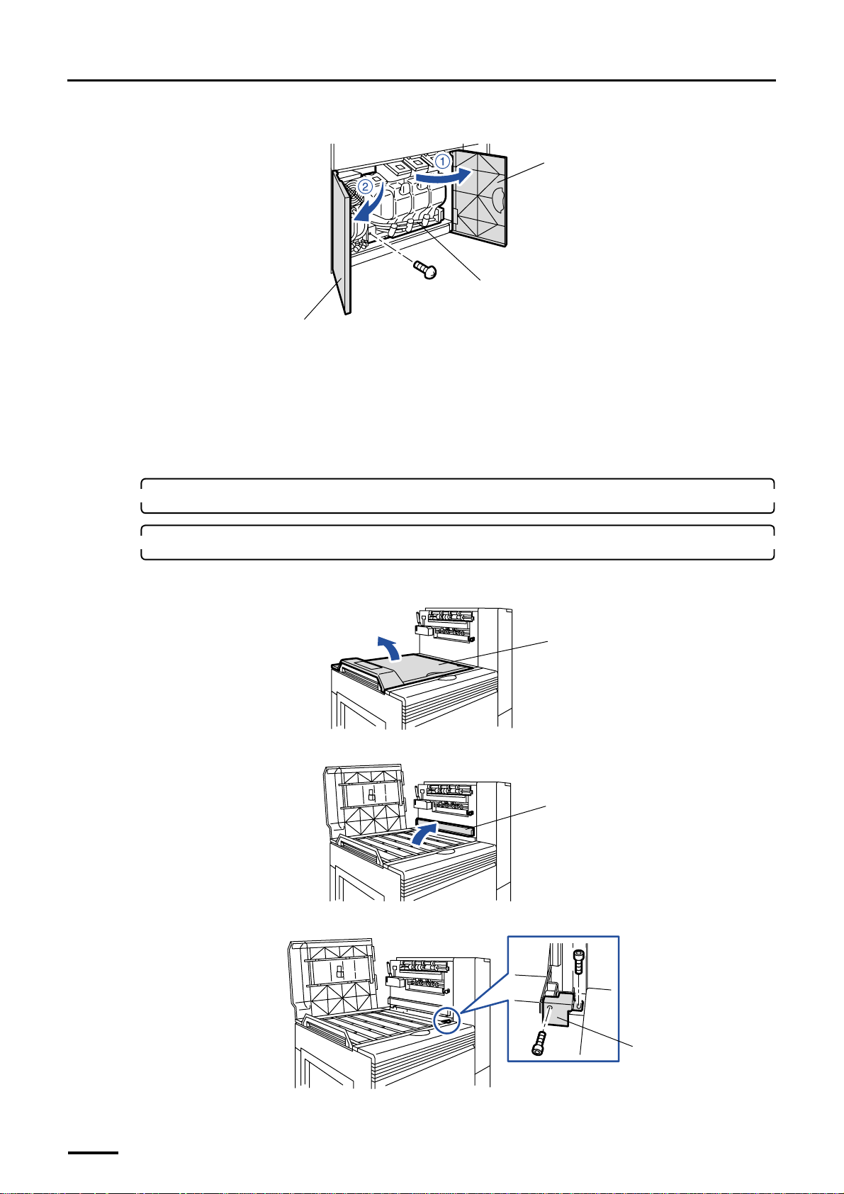
3 Removing the packing angle brackets
Distributed by: minilablaser.com
(2) Remove the packing screw.
Processor door
Replenishment unit
Processor door
(3) Close the processor doors.
This completes removing the packing angle brackets in the paper processor section.
3.2.2 Paper processor section [SM]
Do not use the packing angle brackets and packing screws you have removed from the machine. Only use them when you are
instructed to do so.
1. Remove all the cardboards, adhesive tapes, ropes and packing materials from the machine.
2. Remove the packing angle brackets from the dryer section.
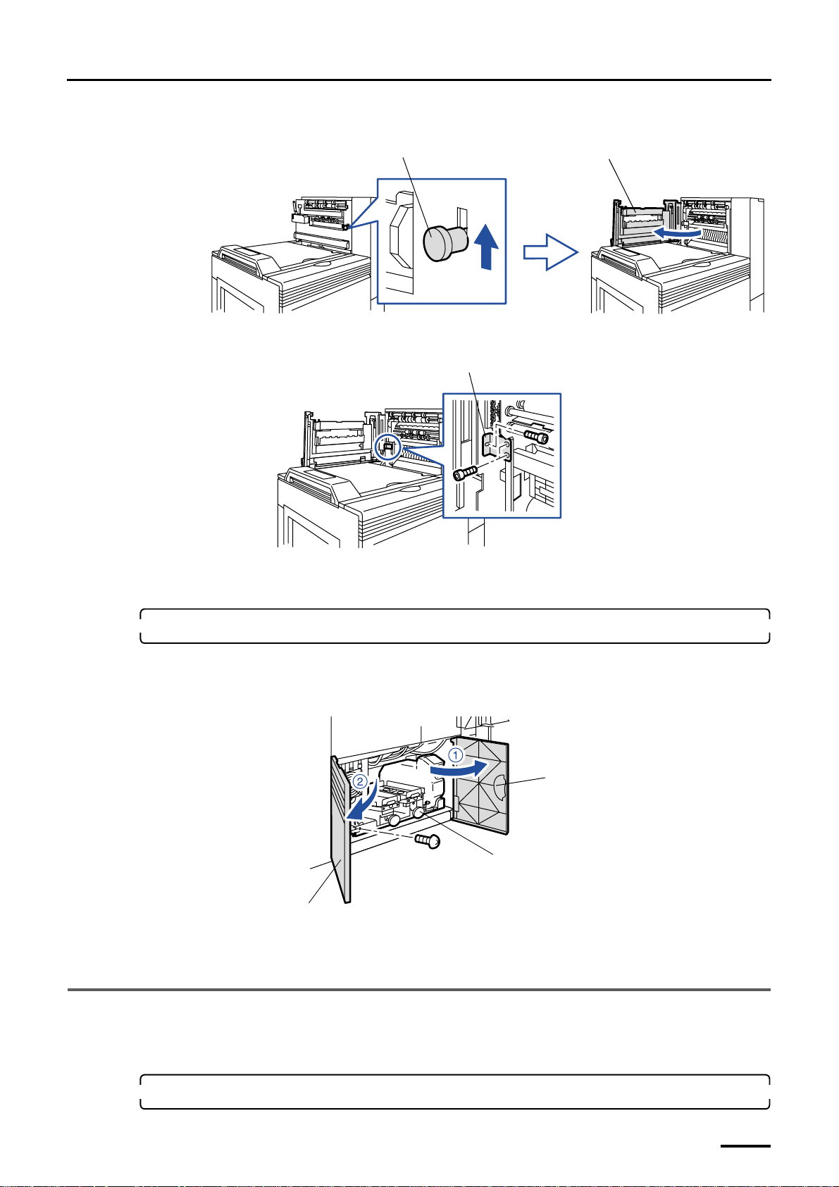
(1) Open the processor top cover.
(2) Open the squeegee unit top cover.
G068914
Processor top cover
G071516
(3) Remove packing angle bracket 1. (two packing screws)
(4) Close the processor top cover.
16
Squeegee unit top cover
G071514
Packing angle bracket 1
G072510
Page 31
3 Removing the packing angle brackets
Distributed by: minilablaser.com
(5) Raise the lever and open the dryer door.
Lever
(6) Remove packing angle bracket 2. (three packing screws)
Packing angle bracket 2
Dryer door
G068887
(7) Close the dryer door.
(8) Close the squeegee unit top cover.
3. Remove the packing screw from the replenishment unit.
(1) Open the processor doors.
(2) Remove the packing screw.
Processor door
Replenishment unit
Processor door
(3) Close the processor doors.
This completes removing the packing angle brackets in the paper processor section [SM].
G068888
G070342
3.3 Desk section
Do not use the packing angle brackets and packing screws you have removed from the machine. Only use them when you are
instructed to do so.
1. Remove all the cardboards, adhesive tapes, ropes and packing materials from the machine.
17
Page 32
3 Removing the packing angle brackets
Distributed by: minilablaser.com
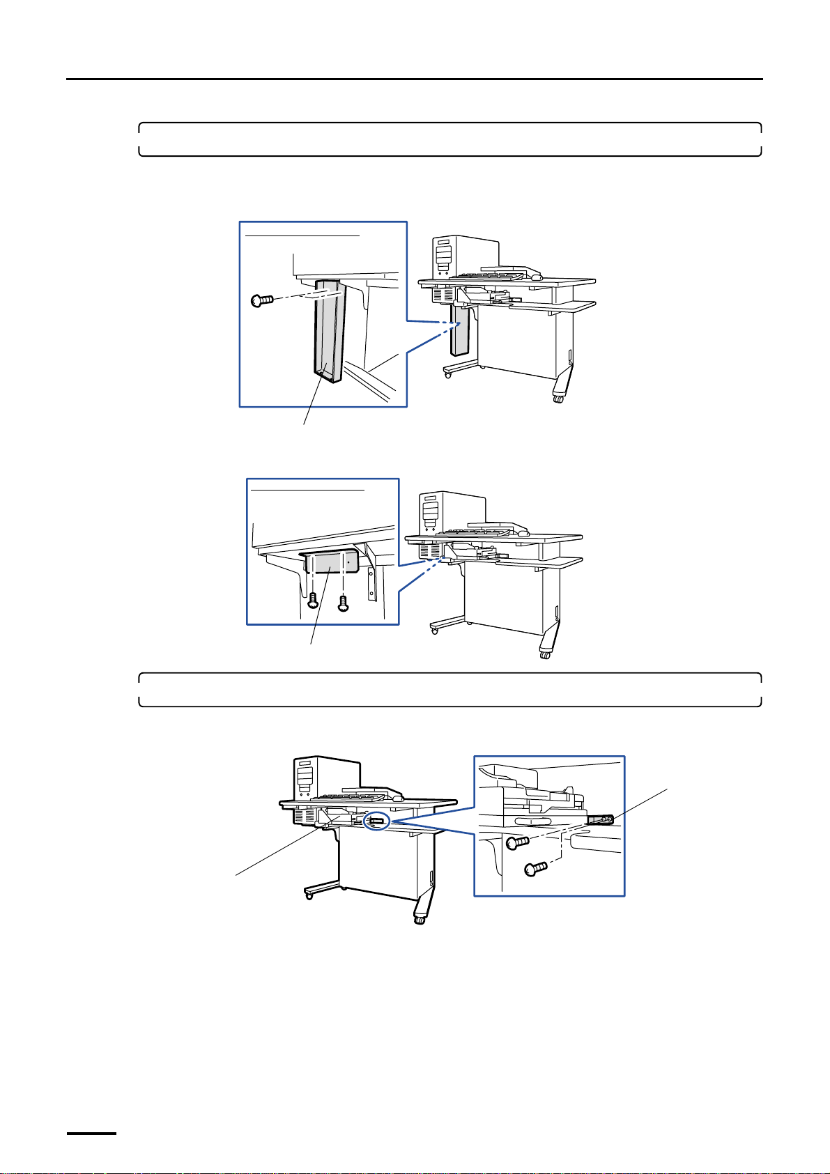
2. Remove the packing angle brackets from the desk section.
These brackets are attached to the machine shipped outside Japan.
(1) Remove packing angle bracket 1. (two packing screws)
Viewed from the left side
Packing angle bracket 1
(2) Remove packing angle bracket 2. (two packing screws)
Viewed from the left side
Packing angle bracket 2
3. Remove the packing angle bracket from the colorimeter unit.
(1) Remove the two packing screws fixing the packing angle bracket.
G072516
G072517
Packing angle
bracket
Colorimeter unit
18
G068921
Page 33
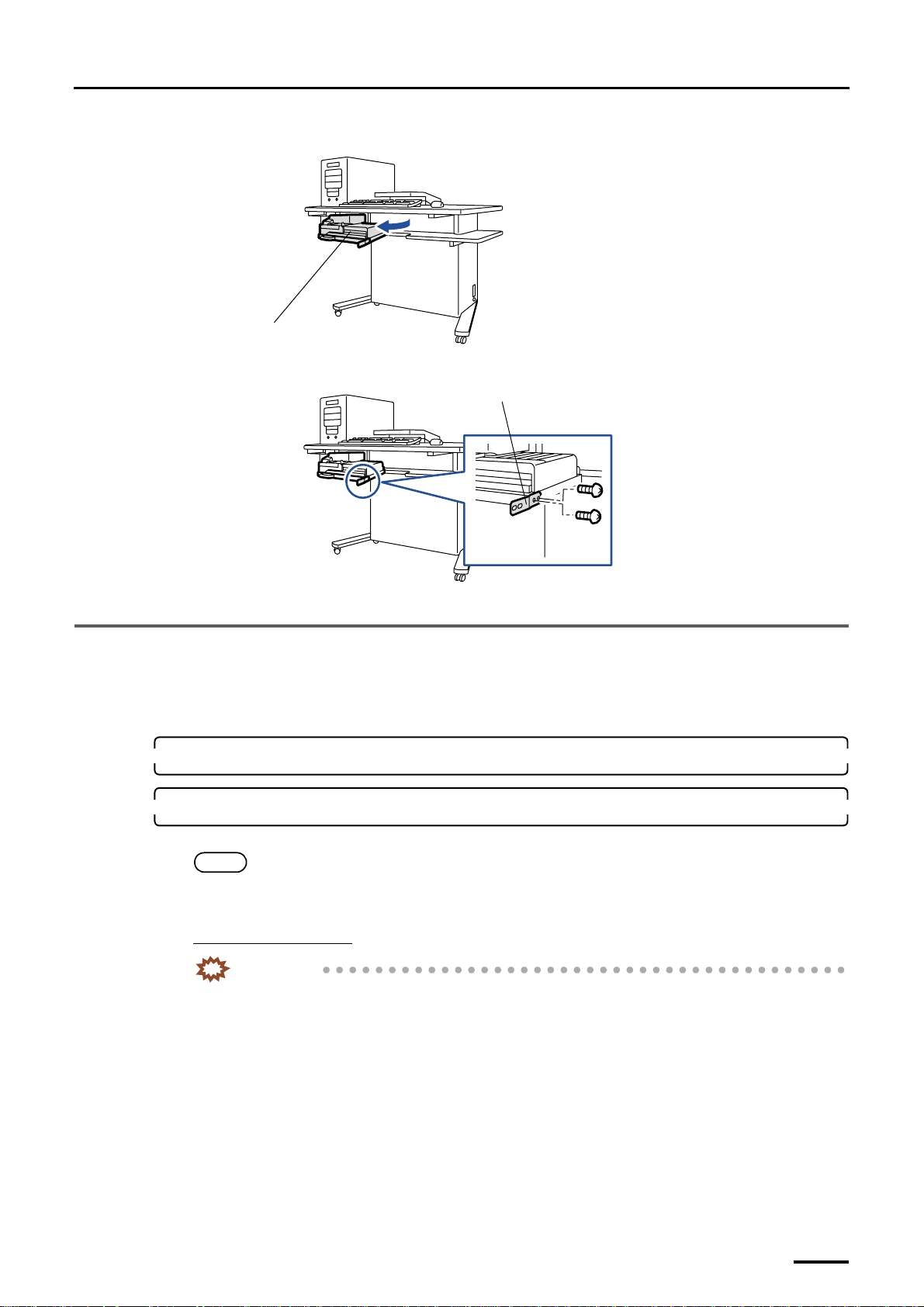
(2) Pull out the colorimeter unit.
Distributed by: minilablaser.com
3 Removing the packing angle brackets
Colorimeter unit
(3) Remove the packing angle bracket. (two screws)
Packing angle bracket
This completes removing the packing angle brackets in the desk section.
3.4 Scanner section
This is for the machine with the scanner.
Do not use the packing angle brackets and packing screws you have removed from the machine. Only use them when you are
instructed to do so.
1. Remove all the cardboards, adhesive tapes, ropes and packing materials from the machine.
G072515
G068922
2. Remove the packing angle bracket from the film carrier.
This operation is necessary only when installing optional 135/240 AFC-II, 135/240 MMC-II or 135/240 AMC-II.
NOTE
• Film carriers other than the 135/240 AFC-II, 135/240 MMC-II and 135/240 AMC-II have no packing angle
bracket.
For the 135/240 AFC-II
IMPORTANT
• When removing the packing angle brackets, place the 135/240 AFC-II on a flat table or the like.
If you remove the packing angle brackets with the 135/240 AFC-II inclined, the 135/240 lane may
quickly switch and the cables inside the film carrier may be damaged.
19
Page 34
3 Removing the packing angle brackets
Distributed by: minilablaser.com
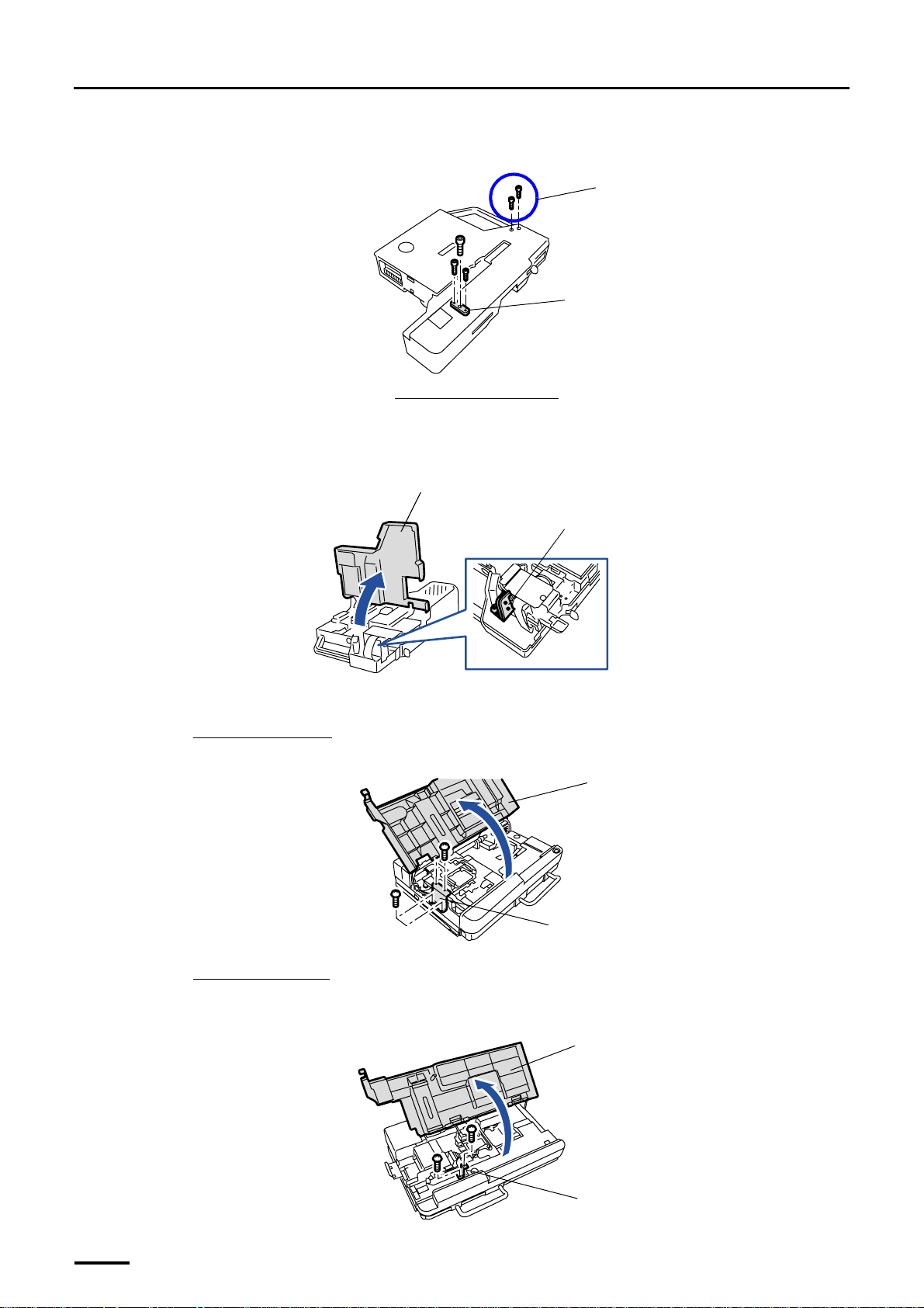
(1) Remove packing angle bracket 1 (three packing screws) and bracket 2 (two packing screws) from the
back of the 135/240 AFC-II.
Packing screws for packing angle
bracket 2
Packing angle bracket 1
Back side of the 135/240 AFC-II
G068995
(2) Turn up the 135/240 AFC-II.
(3) Open the top cover of the 135/240 AFC-II and remove packing angle brackets 2 and 3. (These brackets
are fixed with screws).
Top cover
Packing angle brackets 2 and 3
G068994
(4) Close the top cover.
For 135/240 MMC-II
(1) Open the 135/240 MMC-II top cover and remove the packing angle bracket. (two packing screws)
Top cover
For 135/240 AMC-II
(1) Open the top cover of the 135/240 AMC-II and remove the packing angle bracket. (two packing
screws)
20
Packing angle bracket
G070267
Top cover
Packing angle bracket
G070268
Page 35

3 Removing the packing angle brackets
Distributed by: minilablaser.com
This completes removing the packing angle brackets in the scanner section.
21
Page 36
4 Installing the component parts and units
Distributed by: minilablaser.com
4 Installing the component parts and units
4.1 Printer section
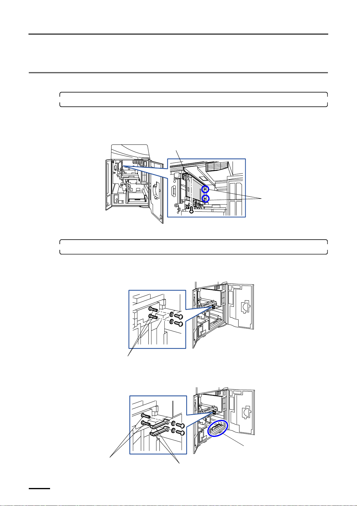
1. Attach the scratch prevention guide.
(1) Open printer doors 1 and 2.
(2) Loosen two fixing screws for the printer, align the screw holes on the scratch prevention guide with the
two screws of printer and then attach it securely. (one screw)
Scratch prevention guide
Loosen these screws.
(3) Tighten the two screws you loosened in the previous step.
2. Attach the lock levers to magazine deck units B and C.
(1) Remove two fixing screws and two washers from the shafts.
Removed screws and washers are necessary in the next step.
Shafts
(2) Take the two lock levers out of the bag and attach them to the shafts. Attach them with the screws and
washers you removed in the previous step.
G068936
G070352
22
Shafts
Lock levers
Bag containing the lock lever
G068882
Page 37
4 Installing the component parts and units
Distributed by: minilablaser.com
3. Attach the ribbon cassette to the CVP unit.
This is for the machine with the optional CVP unit.
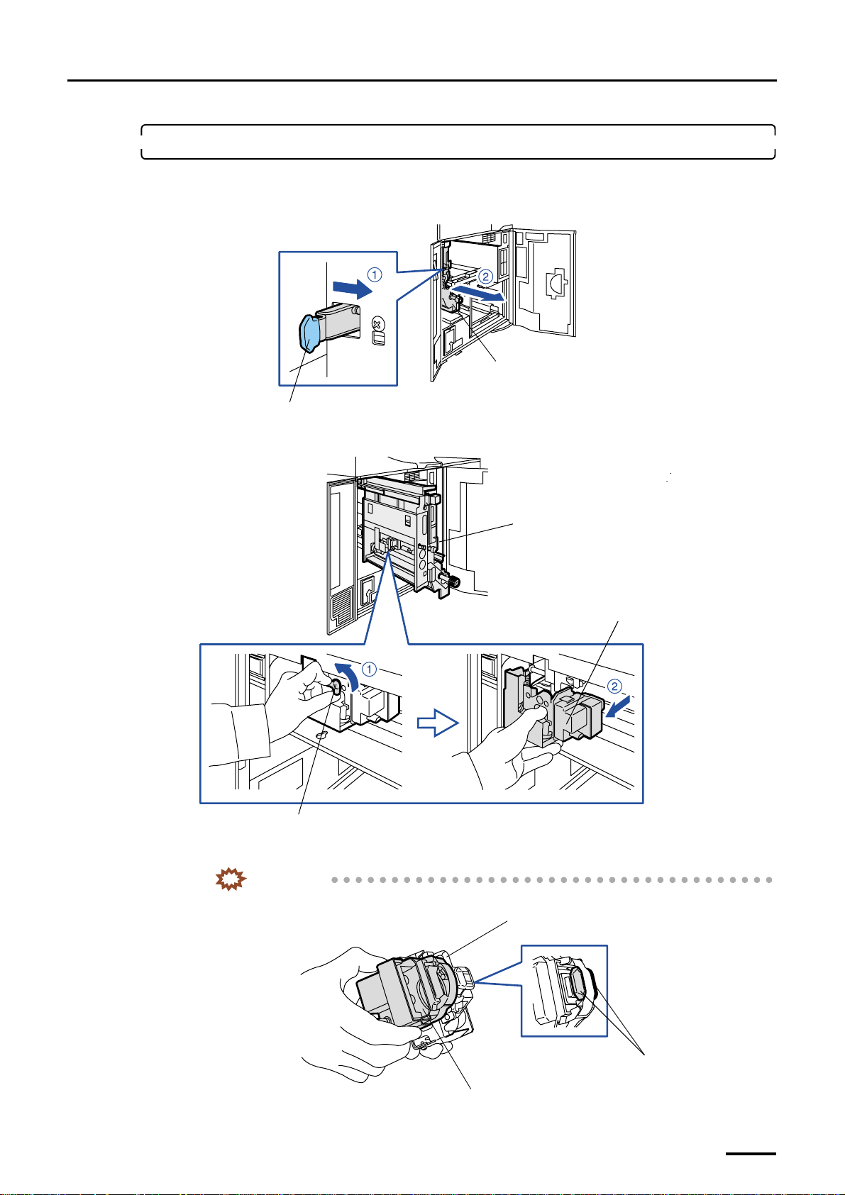
(1) Pull out the paper supply unit while pushing the lock lever to the right.
Paper supply unit
Lever
(2) Loosen one wing screw to remove the CVP unit.
G068999
Paper supply unit
CVP unit
(3) Attach the ribbon cassette to the CVP unit.
• If the ribbon guide is dirty, wipe off the dirt before attaching it.
Wing screw
IMPORTANT
CVP unit
Ribbon cassette
G068900
Ribbon guide
G068901
23
Page 38
4 Installing the component parts and units
Distributed by: minilablaser.com
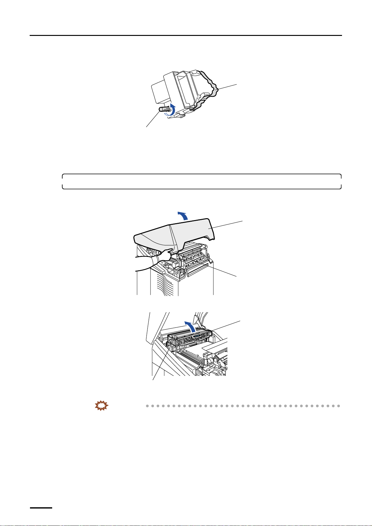
• If the ribbon is loose, turn the knob on the ribbon cassette in the arrow direction to make it tight
before attaching it to the CVP unit.
Ribbon
Knob
(4) Reattach the CVP unit as it was.
(5) Return the paper supply unit to its original position.
(6) Close printer doors 1 and 2.
4. Attach the pressure guide to the exposure advance unit.
(1) Hold the handle and open the printer top cover slowly.
(2) Hold the handle and open paper advance unit 1.
G072034
Printer top cover
Handle
G068884
Paper Advance Unit 1
(3) Attach the pressure guide while holding its handle.
IMPORTANT
• Be careful not to damage the pressure guide.
Handle
G071518
24
Page 39
4 Installing the component parts and units
Distributed by: minilablaser.com
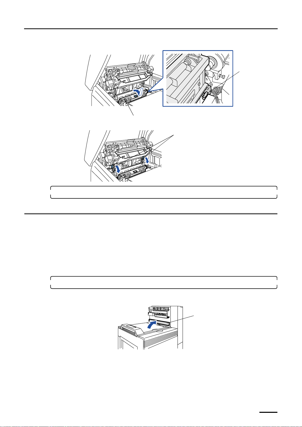
• Attach the pressure guide holding with your hand securely.
Align the pressure
guide pin to the
guide.
Pressure guide
(4) Fix it with the two lock levers.
Lock levers
5. Close paper advance unit 1 and the printer top cover.
This completes installing the component parts and units in the printer section.
4.2 Paper Processor
Depending on the specifications, attaching method of each part or unit for the paper processor differs.
Make sure the machine specification before start working.
• For the normal specification, refer to
• For SM specification, refer to
☞4.2.1 Paper processor section [N].
☞4.2.2 Paper processor section [SM].
G072518
G072519
4.2.1 Paper processor section [N]
1. Attach the roller to the dryer door.
(1) Open the squeegee unit top cover.
Squeegee unit top cover
G070259
25
Page 40
4 Installing the component parts and units
Distributed by: minilablaser.com
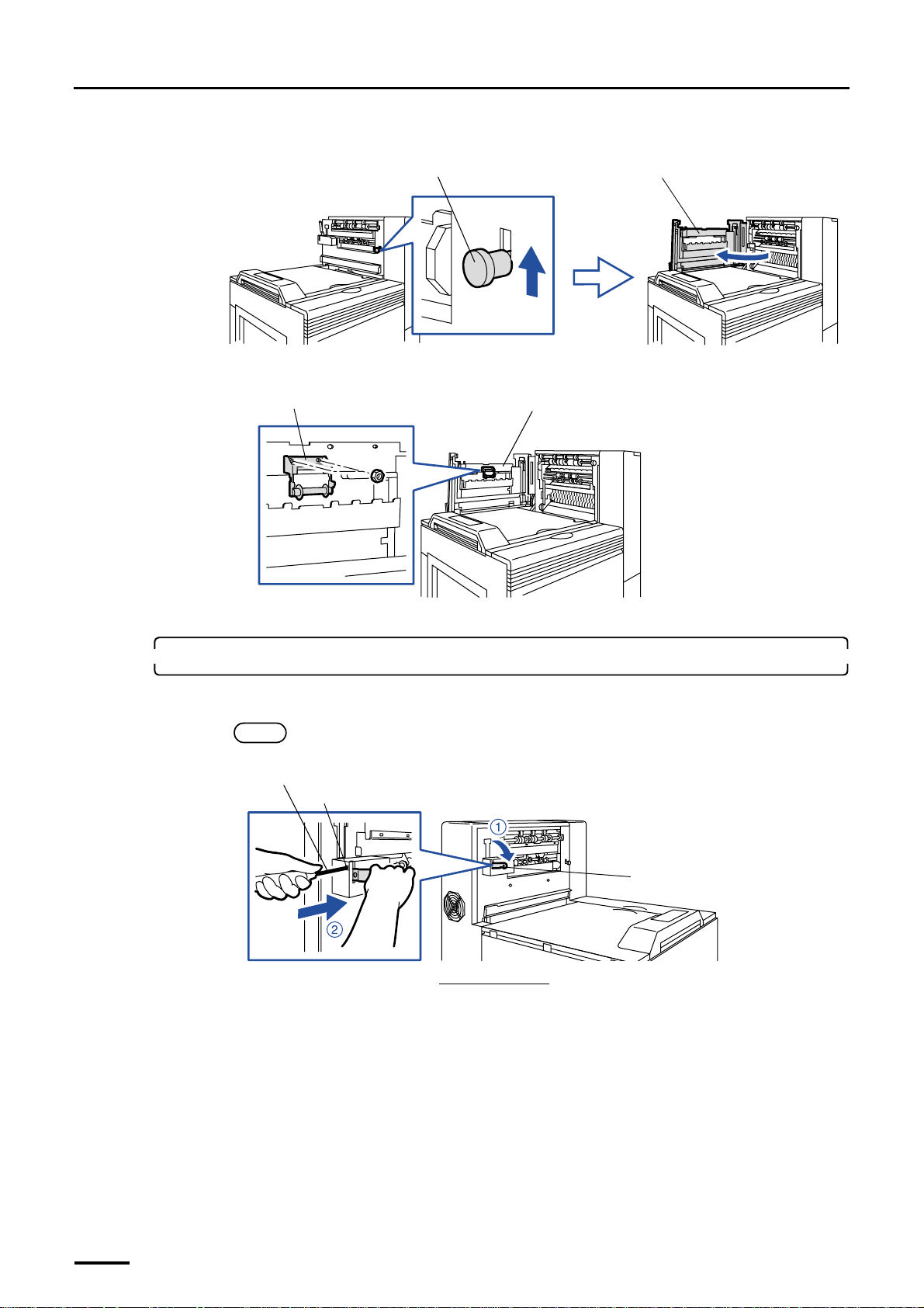
(2) Raise the lever and open the dryer door.
(3) Attach the roller. (two nuts)
Roller
Lever
Dryer door
G068887
Dryer door
(4) Close the dryer door.
2. Attach the print conveyor unit.
(1) Lower conveyor stay 2 and insert the philips blade screwdriver (large) to the square hole.
NOTE
• This step is for not damaging the print conveyor unit when attaching it.
Philips blade screwdriver (large)
Square hole
Conveyor stay 2
Viewed from the back
G068889
G068959
26
Page 41
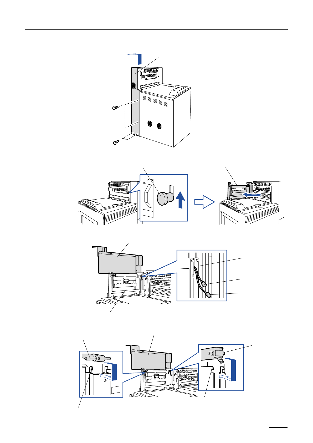
(2) Remove the processor drive cover. (four screws)
Distributed by: minilablaser.com
Processor drive cover
(3) Raise the lever and open the dryer door.
Lever Dryer door
4 Installing the component parts and units
G068892
(4) Pass the cable connectors from the print conveyor unit through the slot on the dryer door.
Print conveyor unit
Slot
J/P778
J/P711
Dryer door
(5) Hook the two fulcrum shafts on print conveyor unit onto the shaft holders on dryer door.
Fulcrum shaft
Print conveyor unit
G068887
G068974
Fulcrum shaft
Shaft holder
Shaft holder
G068890
27
Page 42
4 Installing the component parts and units
ld
Distributed by: minilablaser.com
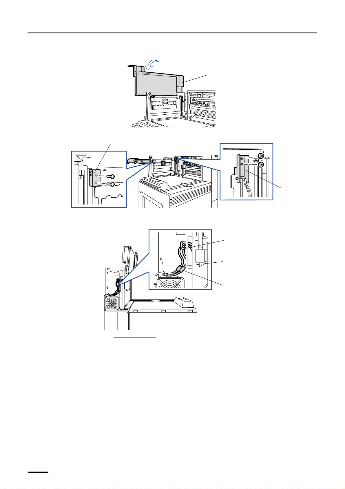
(6) Lay the print conveyor unit down.
(7) Attach holder 1 (two screws) and holder 2 (two nuts).
er 1
Ho
Print conveyor unit
G068998
Holder 2
G068891
(8) Connect the two connectors from the print conveyor unit on the back of processor section and fix the
cables with the clamp.
Clamp
J/P711
J/P778
Viewed from the back
G068948
(9) Close the dryer door.
(10) Close the squeegee unit top cover.
(11) Close the processor drive cover. (four screws)
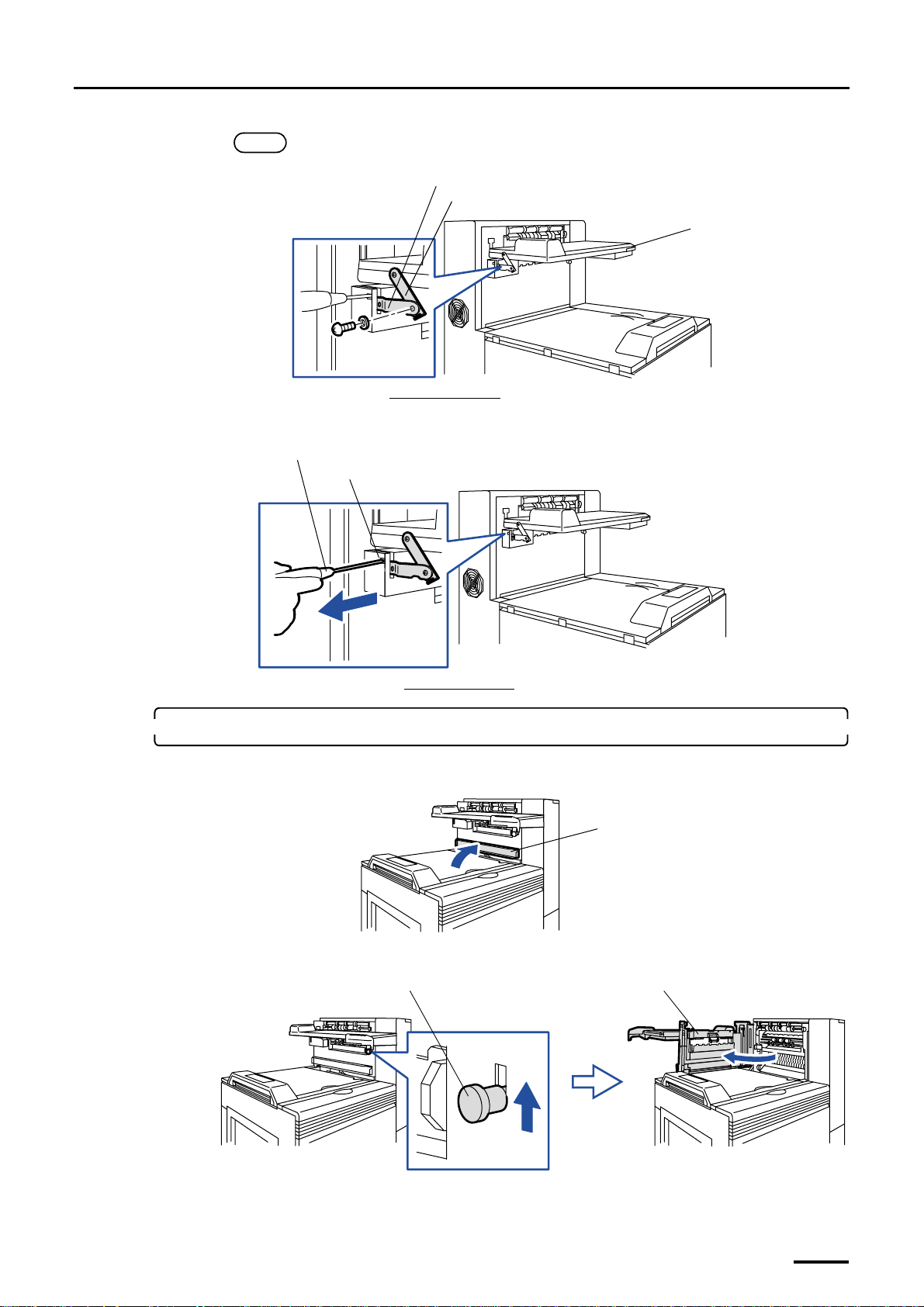
(12) Attach conveyor stay 1 to conveyor stay 2.
Remove the screw from conveyor stay 1 and attach it with the same screw.
28
Page 43
4 Installing the component parts and units
Distributed by: minilablaser.com
NOTE
• If it is hard to attach the plate, lift up the print conveyor unit a little.
Conveyor stay 2
Conveyor stay 1
Print conveyor unit
Viewed from the back
(13) Remove the philips blade screwdriver (large) from the square hole.
Philips blade screwdriver (large)
Square hole
Viewed from the back
3. Attach the conveyor guide to the dryer door.
(1) Open the squeegee unit top cover.
G070290
G068996
Squeegee unit top cover
(2) Raise the lever and open the dryer door.
G072108
Lever Dryer door
G070344
29
Page 44
4 Installing the component parts and units
Distributed by: minilablaser.com
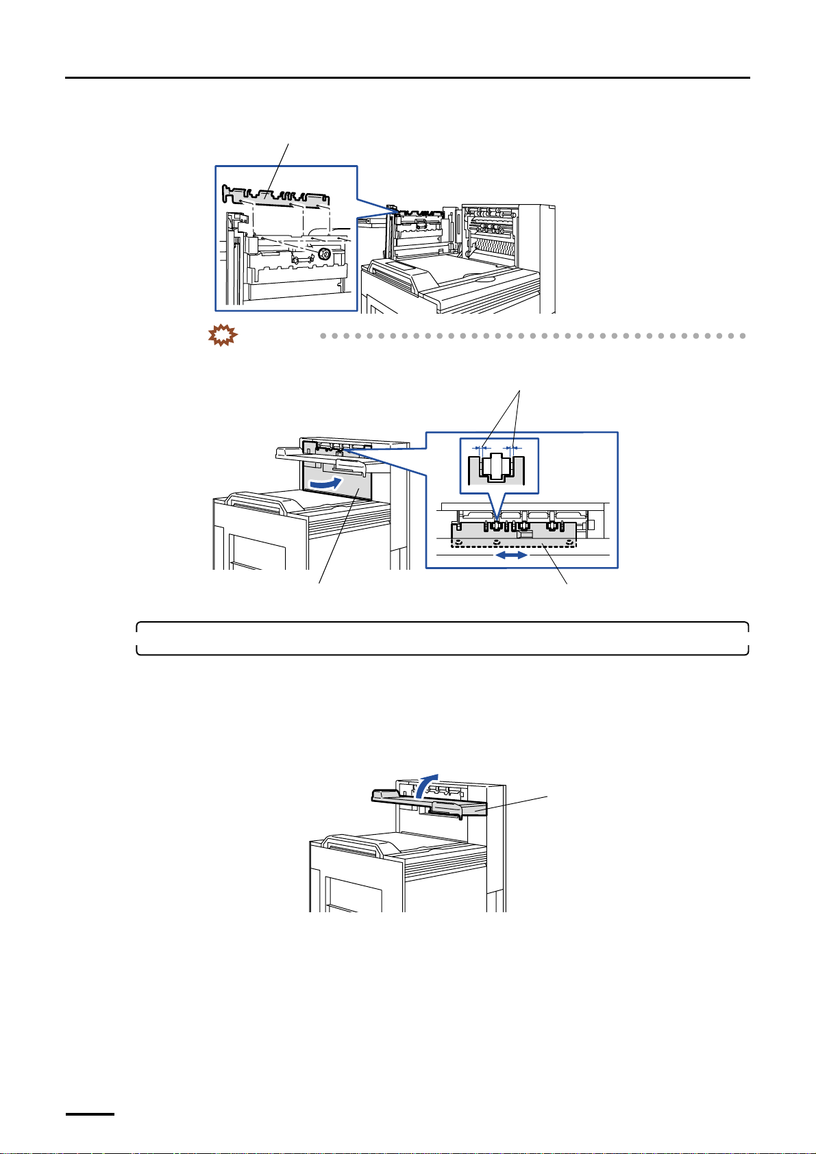
(3) Attach the print conveyor guide. (three nuts)
Conveyor guide
IMPORTANT
• Adjust the conveyor guide attaching position so that the guide may not touch the rollers with
the dryer door closed.
G068895
Move the conveyor guide to the left or right so as
not to come in contact with the rollers.
Dryer door
Conveyor guide
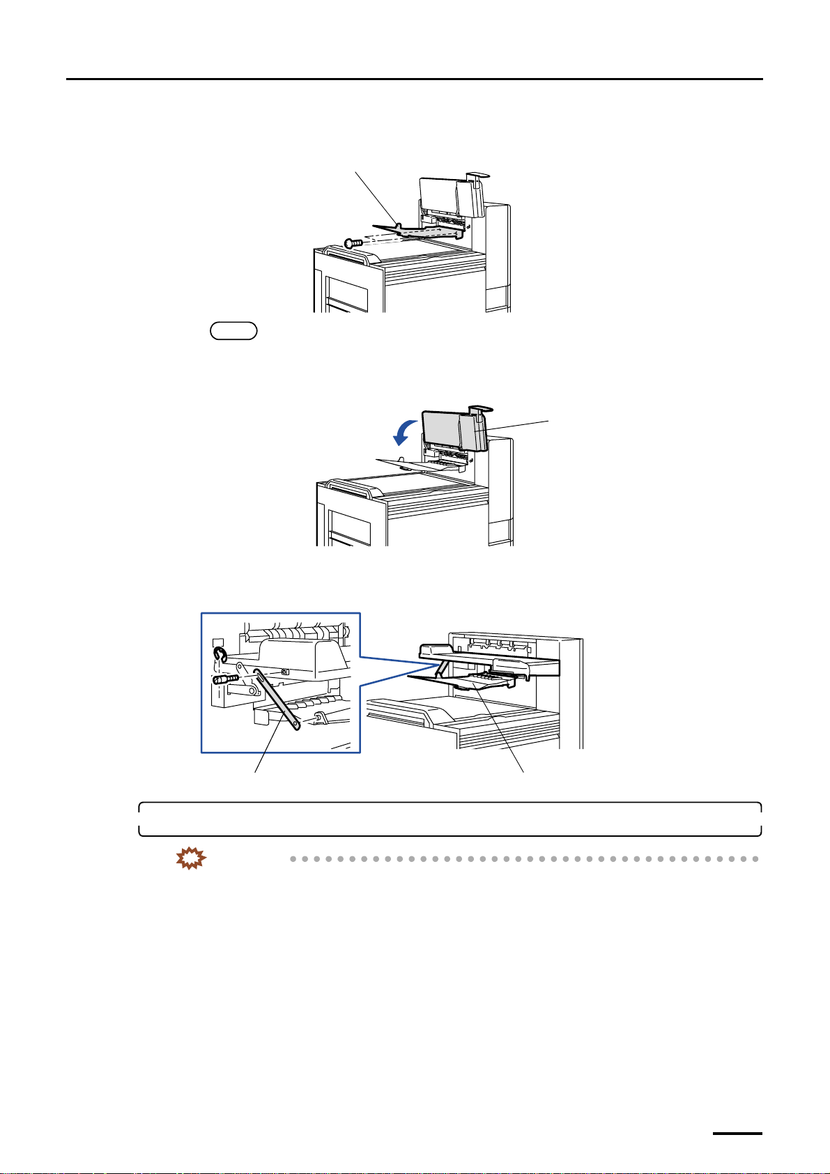
4. Attach the print receiving tray (large).
For the machine with the optional print accumulation tray, you can attach either of print accumulation tray or print
receiving tray (large).
• For the print accumulation tray, attach it after you complete the other works. For details about how to attach the
print accumulation tray, refer to Print Accumulation tray Installation Manual.
(1) Raise the print conveyor unit.
Print conveyor unit
G068997
G069791
30
Page 45
4 Installing the component parts and units
Distributed by: minilablaser.com
(2) Attach the print receiving tray (large). (two screws)
For the print accumulation tray, do not fix the print receiving tray (large) with the screws.
Print receiving tray (large)
NOTE
• For the machine that has both of the print accumulation tray and the print receiving tray (large), do not
fix either of them with the screws so that the customer can replace it easily.
(3) Lower the print conveyor unit.
Print conveyor unit
G068894
(4) Attach the stay to the print receiving tray (large). (one screw and E-ring each)
The screw and the E-ring are attached to the print conveyor unit.
For the machine with the print accumulation tray, you need not attach the stay for print receiving tray (large).
Print receiving tray (large)
Stay
5. Attach the print sorter unit.
IMPORTANT
• Handle the print sorter unit with care not to drop it over your feet.
G069792
G068965
31
Page 46
4 Installing the component parts and units
Distributed by: minilablaser.com
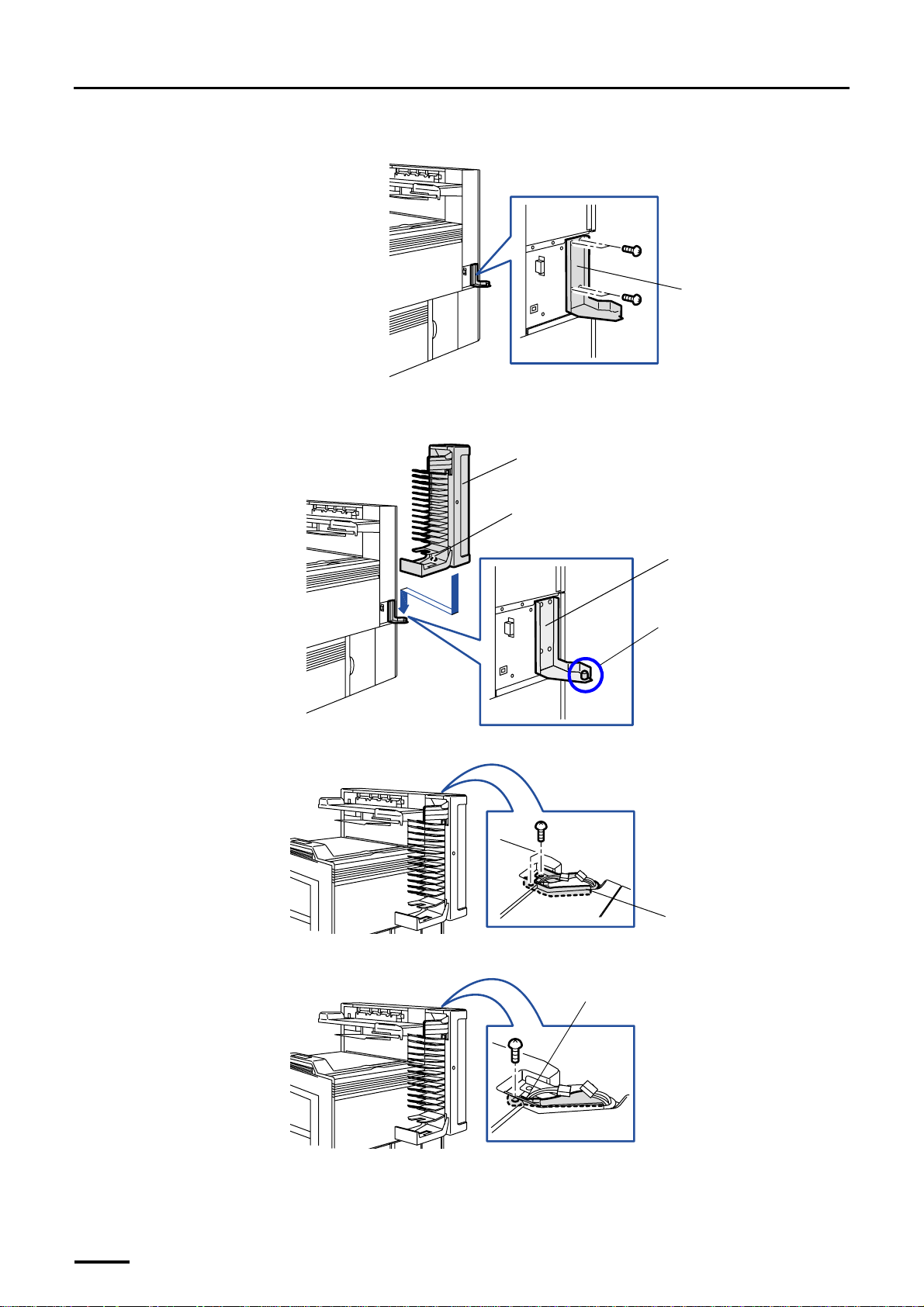
(1) Attach hinge 1. (four screws)
(2) Place the print sorter unit so that the pin of hinge 1 is inserted into the attaching hole of the print sorter
unit.
Hinge 1
G069001
Print sorter unit
Attaching hole
(3) Fix hinge 2. (two screws)
(4) Attach the ground wire. (one screw)
Hinge 1
Pin
G068893
Hinge 2
G070269
Ground wire
32
G070260
Page 47
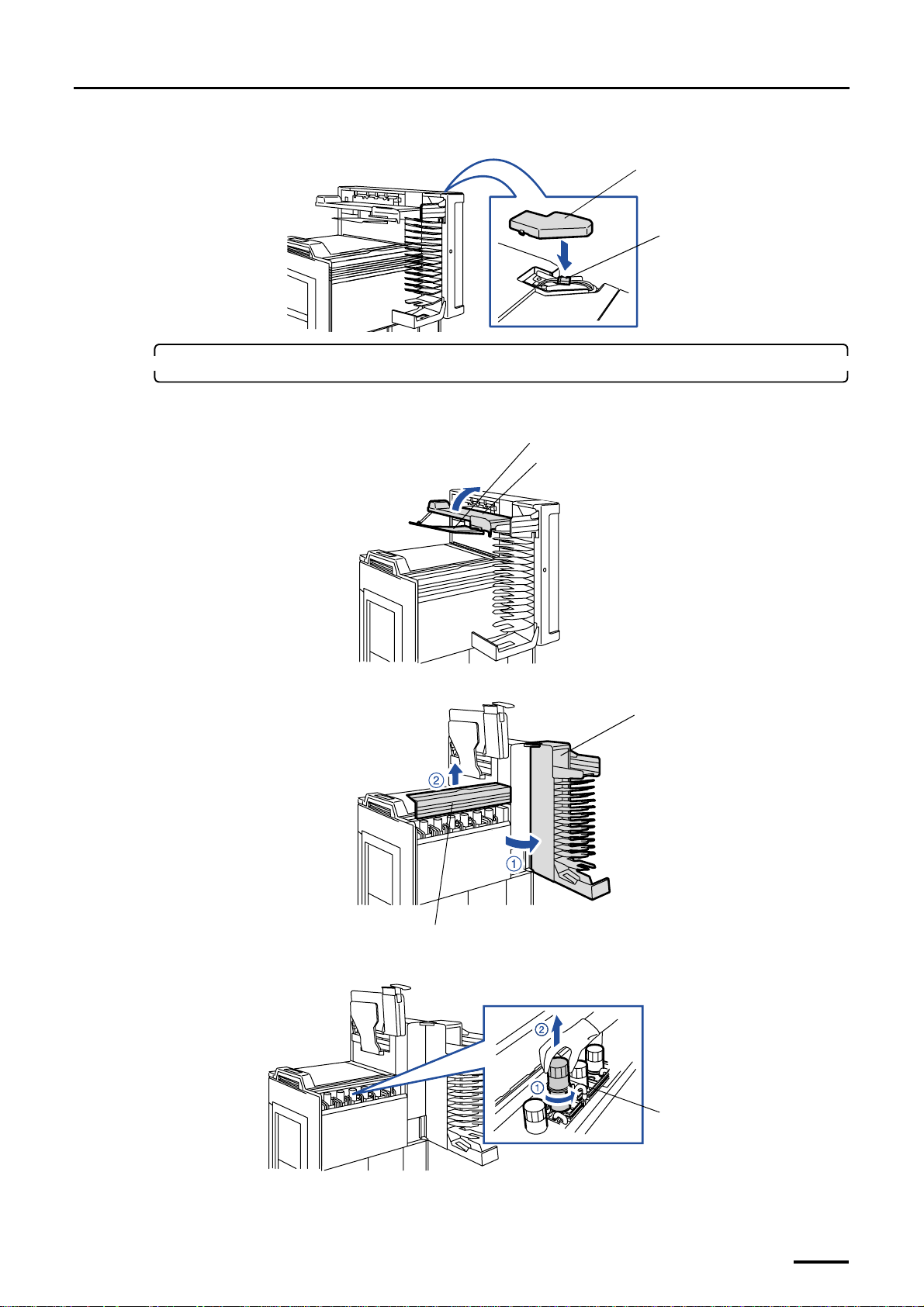
(5) Connect the connector and attach the connector cover.
Distributed by: minilablaser.com
6. Attach the filter cartridge to the filter pipe.
(1) Raise the print conveyor unit and the print receiving tray (large).
4 Installing the component parts and units
Connector cover
J/P713
G068966
Print receiving tray (large)
Print conveyor unit
(2) Open the print sorter unit and remove the sub-tank top cover.
Sub-tank top cover
(3) Turn the filter pipe in the sub-tank counterclockwise and pull it out.
G070349
Print sorter unit
G068969
Filter pipe
G069787
33
Page 48
4 Installing the component parts and units
Distributed by: minilablaser.com
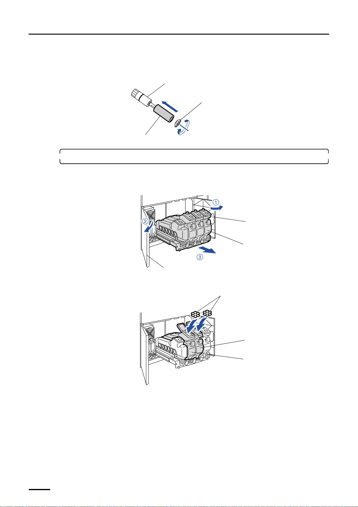
(4) Attach the chemical filter cartridge to the filter pipe and attach the stopper to the filter pipe while
pressing and turning it clockwise.
Install the filter pipe after the processing solution has been poured, as the processing solution is poured into
the sub-tank first.
Filter pipe
Stopper
Filter cartridge
7. Put the floating balls into the replenishment solution tanks.
(1) Open the processor doors.
(2) Pull out the replenishment unit.
Processor door
Replenishment unit
Processor door
(3) Put the floating balls (100 pieces each) into the CD and BF replenishment solution tanks.
For VPII specification, put 160 pieces each into the CD and BF replenishment solution tanks.
Floating balls (100 pieces each)
G069789
G068915
This completes installing the component parts and units in the paper processor section [N].
34
Replenishment solution tank (BF)
Replenishment solution tank (CD)
G068916
Page 49
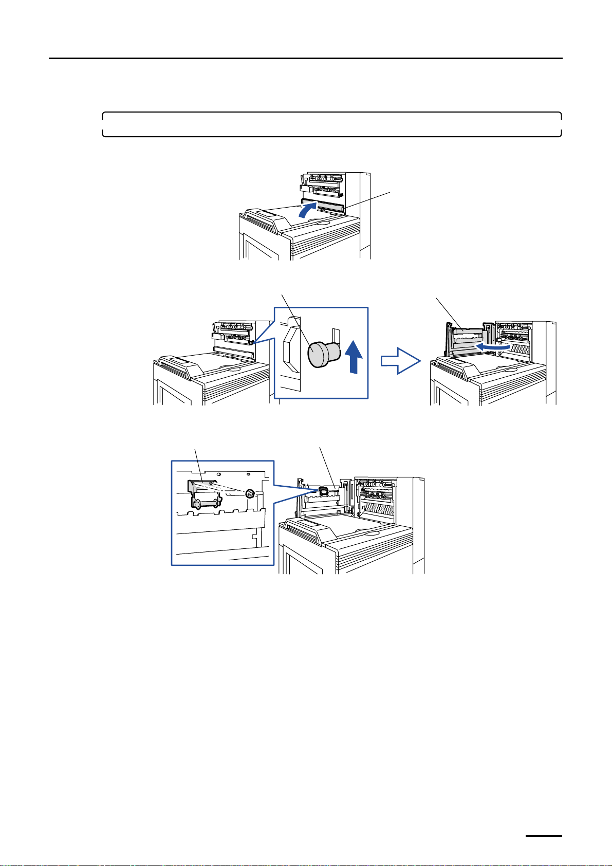
4.2.2 Paper processor section [SM]
Distributed by: minilablaser.com
1. Attach the roller to the dryer door.
(1) Open the squeegee unit top cover.
(2) Raise the lever and open the dryer door.
Lever
4 Installing the component parts and units
Squeegee unit top cover
G070259
Dryer door
(3) Attach the roller. (two nuts)
Roller
(4) Close the dryer door.
G068887
Dryer door
G068889
35
Page 50
4 Installing the component parts and units
Distributed by: minilablaser.com
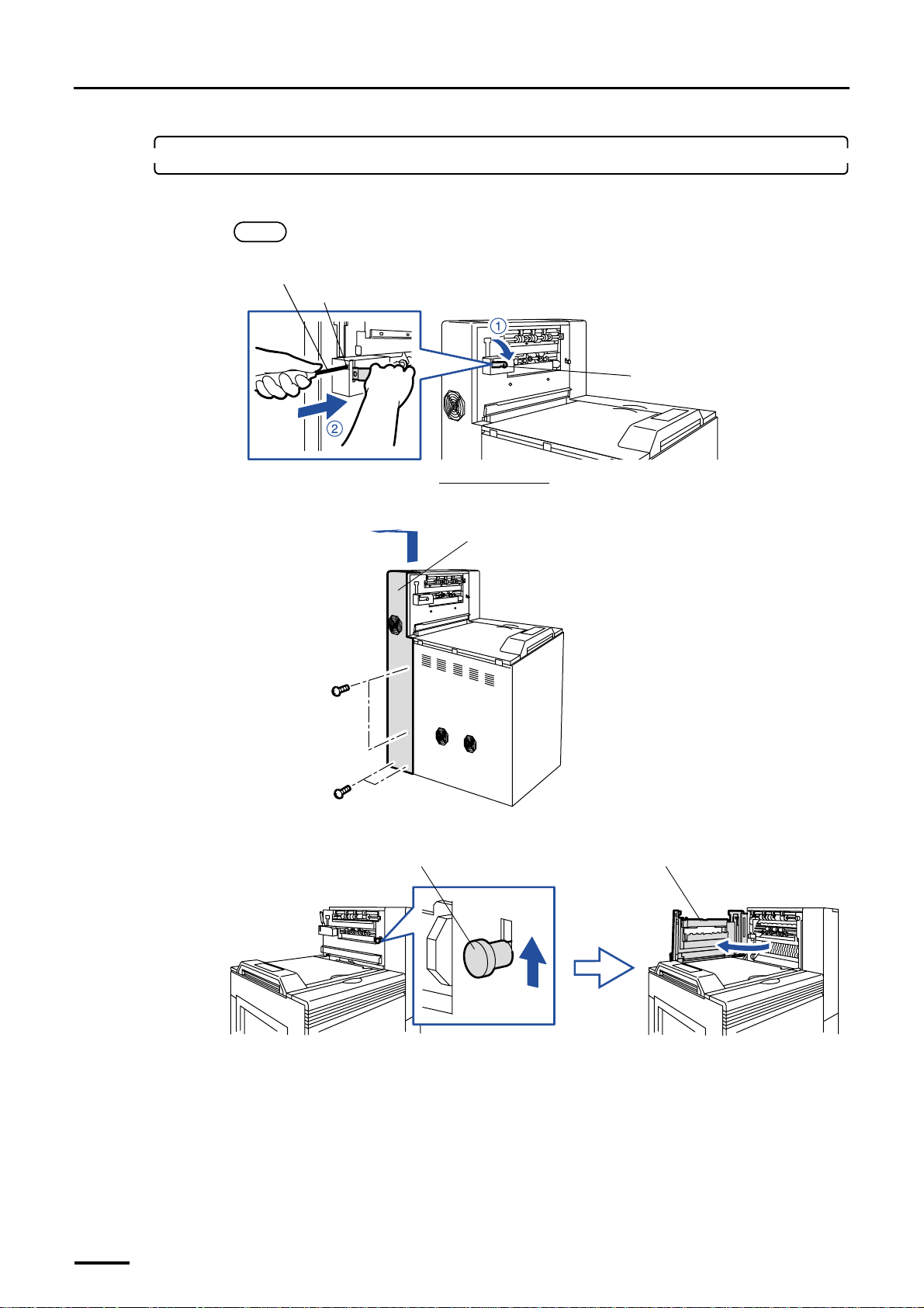
2. Attach the print conveyor unit.
(1) Lower conveyor stay 2 and insert the philips blade screwdriver (large) to the square hole.
NOTE
• This step is for not damaging the print conveyor unit when attaching it.
Philips blade screwdriver (large)
Square hole
Conveyor stay 2
Viewed from the back
(2) Remove the processor drive cover. (four screws)
Processor drive cover
(3) Raise the lever and open the dryer door.
Lever
G068959
G068892
Dryer door
36
G068887
Page 51
4 Installing the component parts and units
ld
Distributed by: minilablaser.com
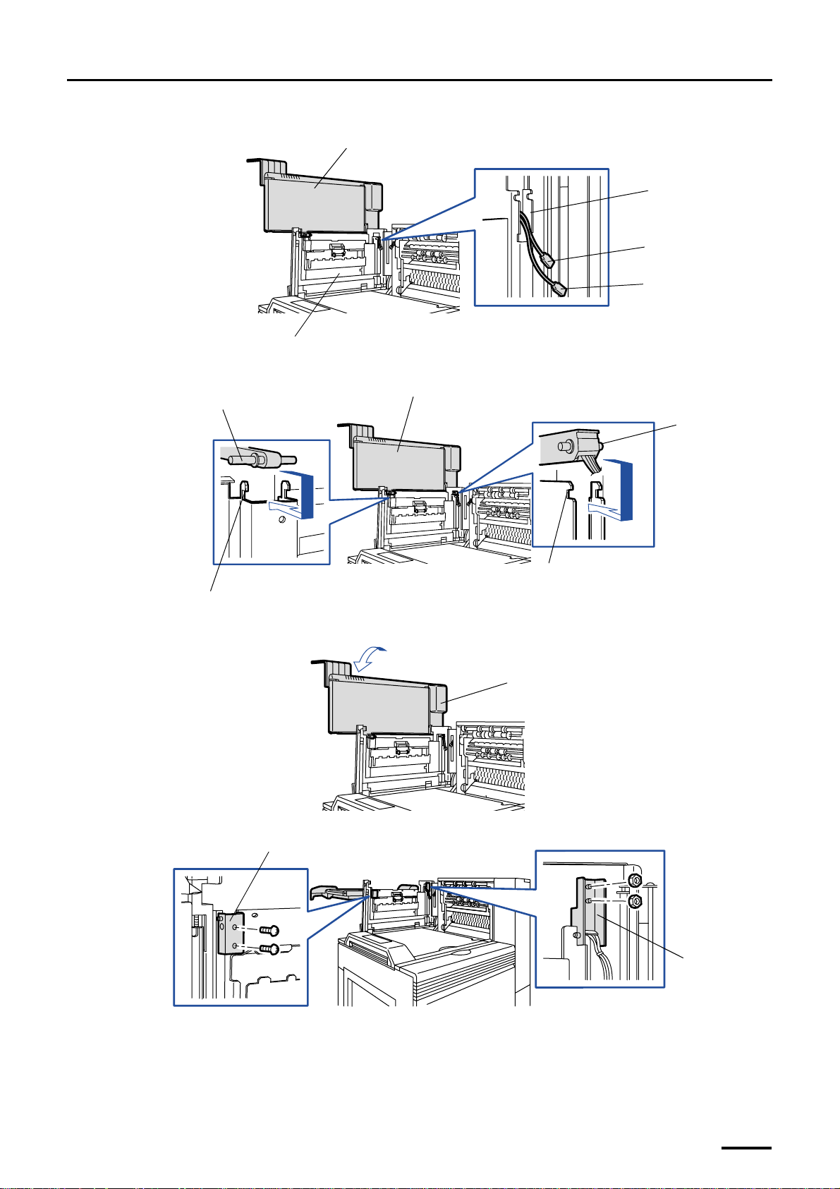
(4) Pass the cable connectors from the print conveyor unit through the slot on the dryer door.
Print conveyor unit
Slot
J/P778
J/P711
Dryer door
(5) Hook the two fulcrum shafts on print conveyor unit onto the shaft holders on dryer door.
Fulcrum shaft
Shaft holder
Print conveyor unit
Shaft holder
(6) Lay the print conveyor unit down.
Print conveyor unit
G068974
Fulcrum shaft
G068890
(7) Attach holder 1 (two screws) and holder 2 (two nuts).
Ho
G068998
er 1
Holder 2
G068891
37
Page 52
4 Installing the component parts and units
Distributed by: minilablaser.com
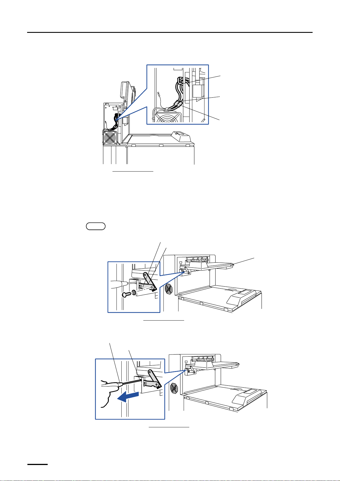
(8) Connect the two connectors from the print conveyor unit on the back of processor section and fix the
cables with the clamp.
Clamp
J/P711
J/P778
Viewed from the back
(9) Close the dryer door.
(10) Close the squeegee unit top cover.
(11) Close the processor drive cover. (four screws)
(12) Attach conveyor stay 1 to conveyor stay 2.
Remove the screw from conveyor stay 1 and attach it with the same screw.
NOTE
• If it is hard to attach the plate, lift up the print conveyor unit a little.
Conveyor stay 2
Conveyor stay 1
Viewed from the back
(13) Remove the philips blade screwdriver (large) from the square hole.
Philips blade screwdriver (large)
Square hole
G068948
Print conveyor unit
G070290
38
Viewed from the back
G068996
Page 53
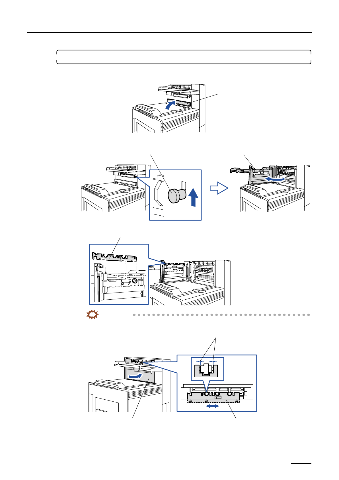
3. Attach the conveyor guide to the dryer door.
Distributed by: minilablaser.com
(1) Open the squeegee unit top cover.
(2) Raise the lever and open the dryer door.
Lever Dryer door
4 Installing the component parts and units
Squeegee unit top cover
G072108
(3) Attach the print conveyor guide. (three nuts)
Conveyor guide
IMPORTANT
• Adjust the conveyor guide attaching position so that the guide may not touch the rollers with
the dryer door closed.
Move the conveyor guide to the left or right so as
not to come in contact with the rollers.
G070344
G068895
Dryer door
Conveyor guide
G068997
39
Page 54
4 Installing the component parts and units
Distributed by: minilablaser.com
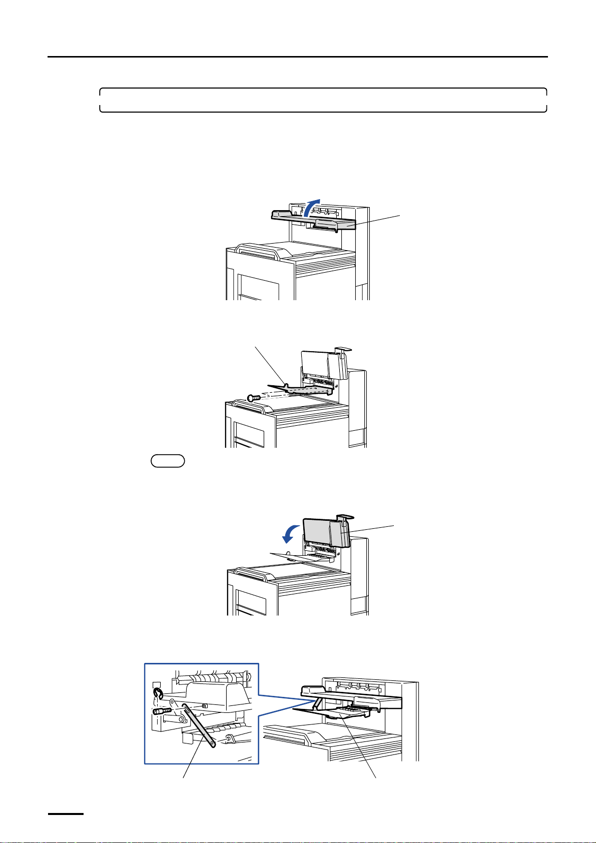
4. Attach the print receiving tray (large).
For the machine with the optional print accumulation tray, you can attach either of print accumulation tray or print
receiving tray (large).
• For the print accumulation tray, attach it after you complete the other works. For details about how to attach the
print accumulation tray, refer to Print Accumulation tray Installation Manual.
(1) Raise the print conveyor unit.
(2) Attach the print receiving tray (large). (two screws)
For the print accumulation tray, do not fix the print receiving tray (large) with the screws.
Print receiving tray (large)
Print conveyor unit
G069791
NOTE
• For the machine that has both of the print accumulation tray and the print receiving tray (large), do not
fix either of them with the screws so that the customer can replace it easily.
(3) Lower the print conveyor unit.
Print conveyor unit
(4) Attach the stay to the print receiving tray (large). (one screw and E-ring each)
The screw and the E-ring are attached to the print conveyor unit.
For the machine with the print accumulation tray, you need not attach the stay for print receiving tray (large).
G068894
G069792
40
Stay
Print receiving tray (large)
G068965
Page 55
4 Installing the component parts and units
Distributed by: minilablaser.com
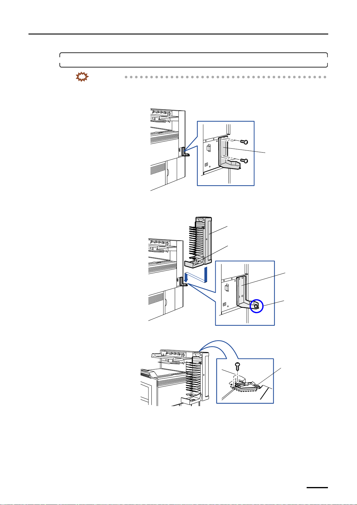
5. Attach the print sorter unit.
IMPORTANT
• Handle the print sorter unit with care not to drop it over your feet.
(1) Attach hinge 1. (four screws)
Hinge 1
(2) Place the print sorter unit so that the pin of hinge 1 is inserted into the attaching hole of the print sorter
unit.
G069001
(3) Fix hinge 2. (two screws)
Print sorter unit
Attaching hole
Hinge 1
Pin
G068893
Hinge 2
G070269
41
Page 56
4 Installing the component parts and units
Distributed by: minilablaser.com
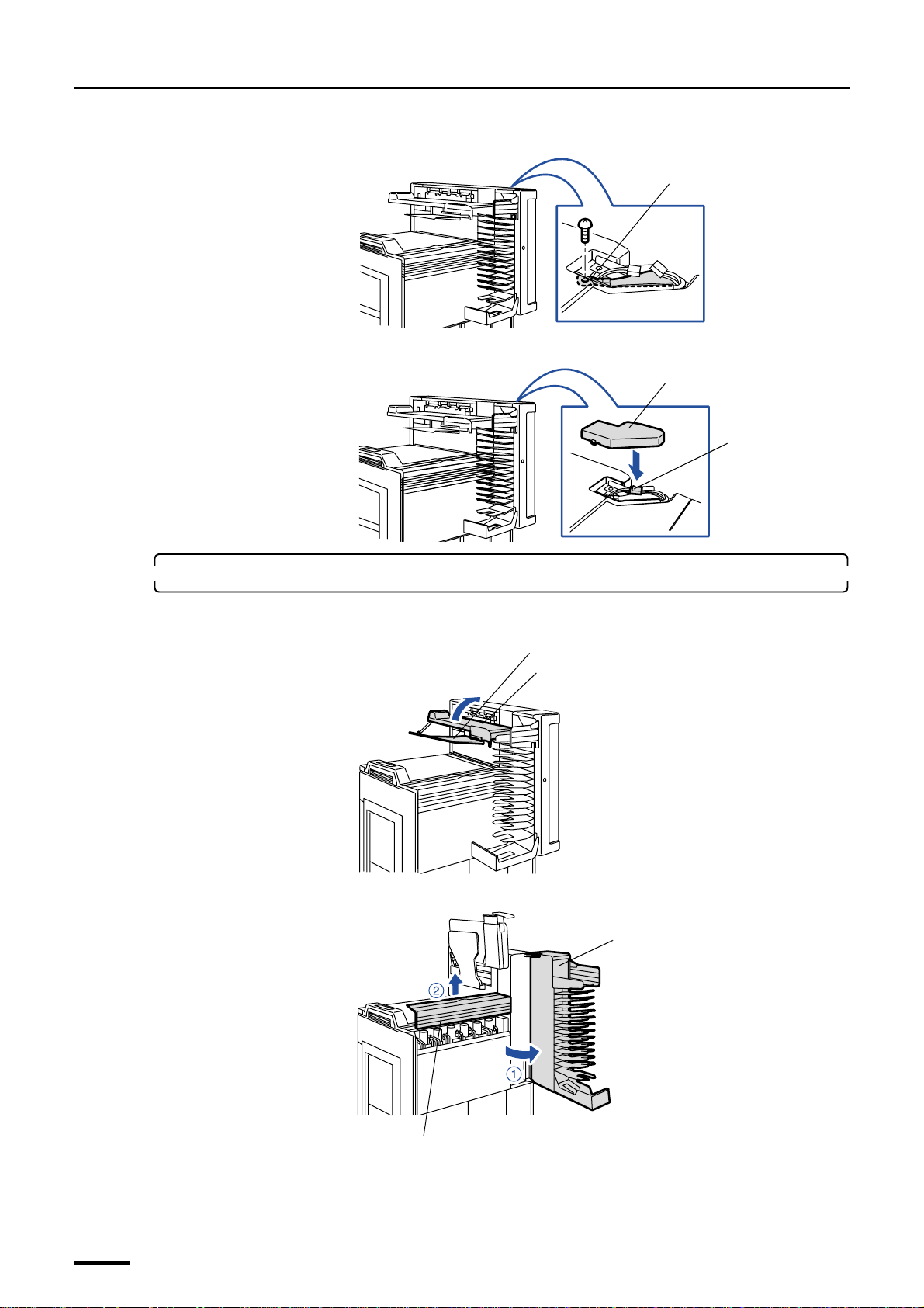
(4) Attach the ground wire. (one screw)
(5) Connect the connector and attach the connector cover.
Ground wire
G070260
Connector cover
J/P713
6. Attach the filter cartridge to the filter pipe.
(1) Raise the print conveyor unit and the print receiving tray (large).
(2) Open the print sorter unit and remove the sub-tank top cover.
G068966
Print receiving tray (large)
Print conveyor unit
G070349
Print sorter unit
42
Sub-tank top cover
G068969
Page 57
4 Installing the component parts and units
Distributed by: minilablaser.com
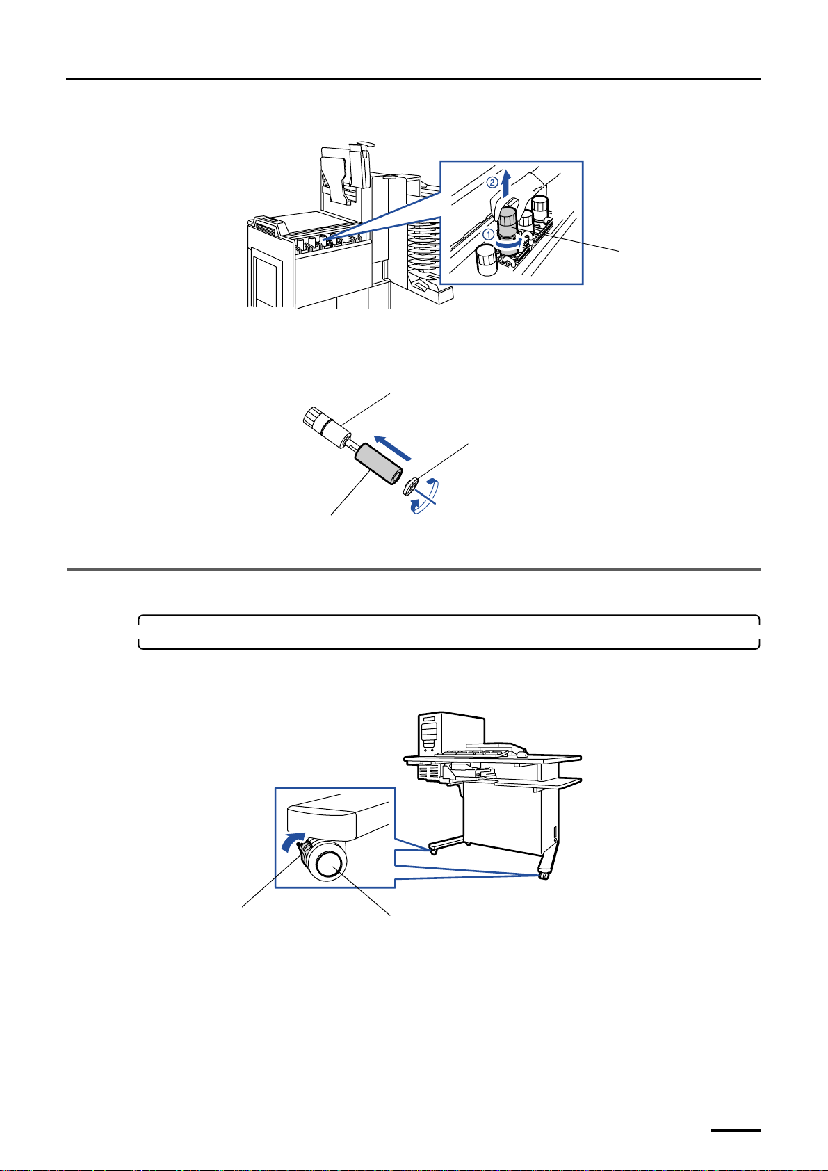
(3) Turn the filter pipe in the sub-tank counterclockwise and pull it out.
Filter pipe
G069787
(4) Attach the chemical filter cartridge to the filter pipe and attach the stopper to the filter pipe while
pressing and turning it clockwise.
Install the filter pipe after the processing solution has been poured, as the processing solution is poured into
the sub-tank first.
Filter pipe
Stopper
Filter cartridge
This completes installing the component parts and units in the paper processor section [SM].
4.3 Desk section
1. Move the desk section to the location intended for installation.
(1) Unlock the castors on the desk section and move it.
Provide enough space for operation around the desk section.
Lock
Castor
G069789
G070343
43
Page 58
4 Installing the component parts and units
Distributed by: minilablaser.com
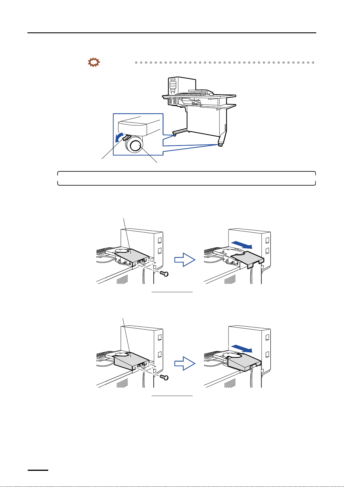
(2) Lock the castors.
IMPORTANT
• Otherwise, you might be injured.
Lock
2. Attach the display monitor.
(1) Remove the monitor table cover. (two screws)
Standard PC:
Monitor table cover
Viewed from the back
High-spec PC:
Monitor table cover
Castor
G068967
G068923
44
Viewed from the back
G068853
Page 59
4 Installing the component parts and units
Distributed by: minilablaser.com
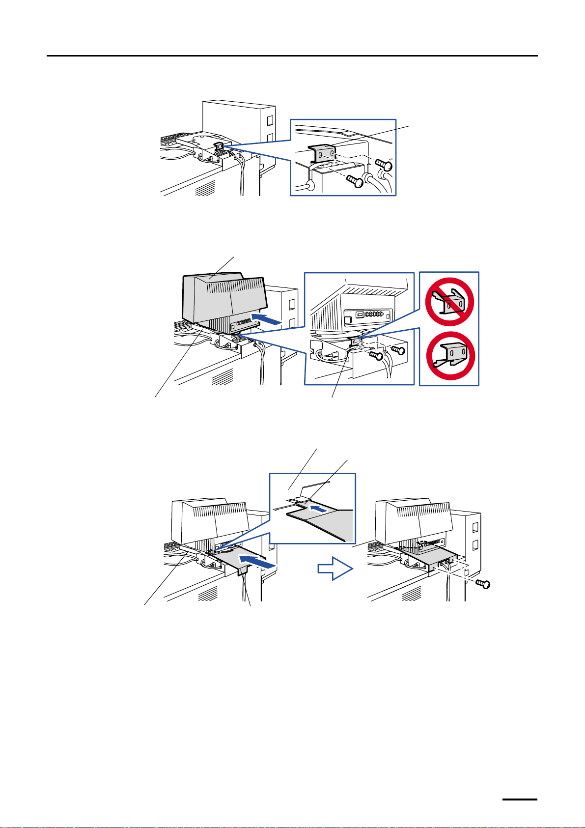
(2) Remove the monitor fixing angle bracket. (two screws)
(3) Place the display monitor on the monitor table unit.
(4) Reattach the monitor fixing angle bracket. (two screws)
Do not attach it in the wrong direction.
Display monitor
Monitor fixing angle bracket
G068924
Monitor table unit
Monitor fixing angle bracket
(5) Reattach the monitor table cover.
Make sure that the monitor table cover is placed under the monitor table unit.
Monitor table unit
Cutout
Monitor table unit
Monitor table cover
G068926
G068854
45
Page 60
4 Installing the component parts and units
Distributed by: minilablaser.com
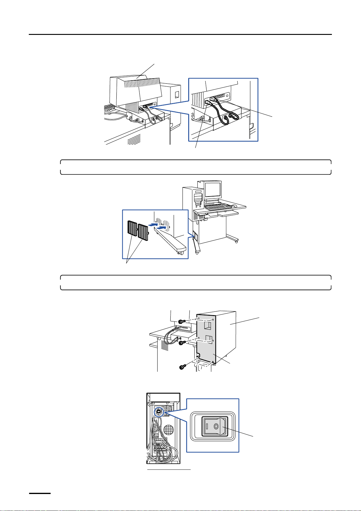
(6) Connect two cables to the display monitor.
Display monitor
Signal cable
3. Attach two air filters.
Air filters
4. Check the PC unit power supply.
(1) Remove the PC rear cover. (six knob screws)
Power supply cable
G069794
G068899
PC unit
(2) Check that the power switch on the back of PC unit is turned ON.
If it is OFF, turn it ON.
46
Viewed from the back
ON
PC rear cover
G068933
Power switch
OFF
G068934
Page 61
4 Installing the component parts and units
Distributed by: minilablaser.com
5. Attach capacity boosters A and B.
This is for the machine with the capacity booster.
For some types of machines, capacity booster A is only to be attached.
6. Reattach the PC rear cover.
This completes installing the component parts and units in the desk section.
Capacity booster B
Capacity booster A
G071499
4.4 Scanner section
This is for the machine with the scanner.
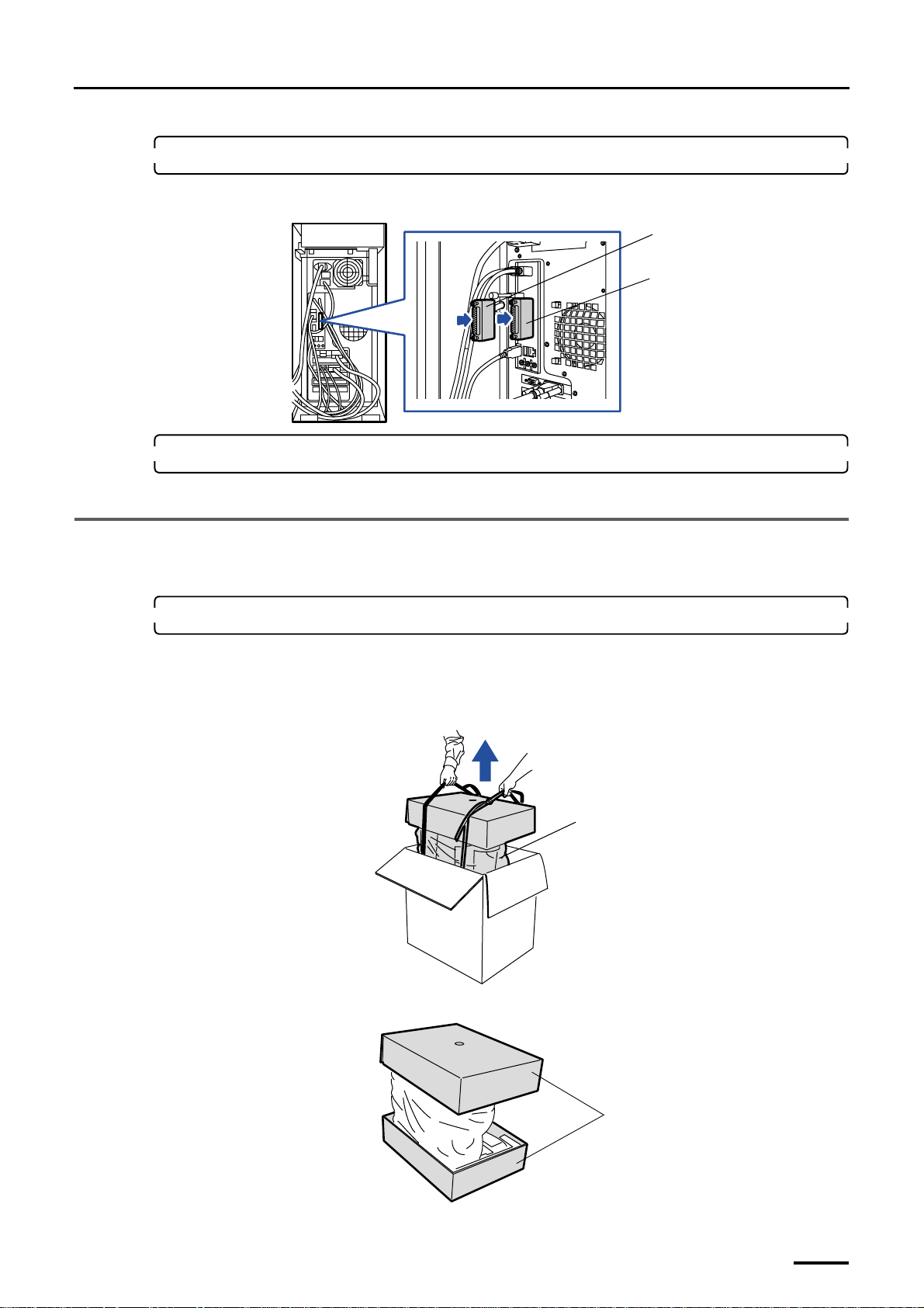
1. Take the scanner out of the box.
(1) Open the box containing the scanner.
(2) Hold the rope and lift up the scanner.
The scanner is pulled up by two persons in this figure.
(3) Remove the rope and packing materials on the top and bottom of scanner.
Scanner
G072520
Packing materials
G073033
47
Page 62
4 Installing the component parts and units
Distributed by: minilablaser.com
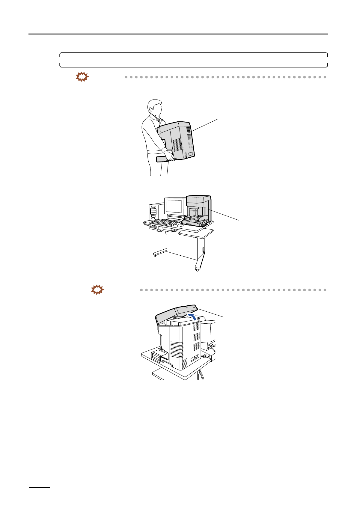
2. Attach the scanner.
IMPORTANT
• When you lift up the scanner, hold it as shown below. Otherwise, you may lose balance and drop the
scanner.
(1) Install the scanner on the desk section.
Scanner
G068855
Scanner
(2) Remove the scanner top cover.
IMPORTANT
• You cannot remove the scanner top cover from the front side. Remove it from the back.
Scanner top cover
Viewed from the rear
G068928
G068929
48
Page 63
4 Installing the component parts and units
Distributed by: minilablaser.com
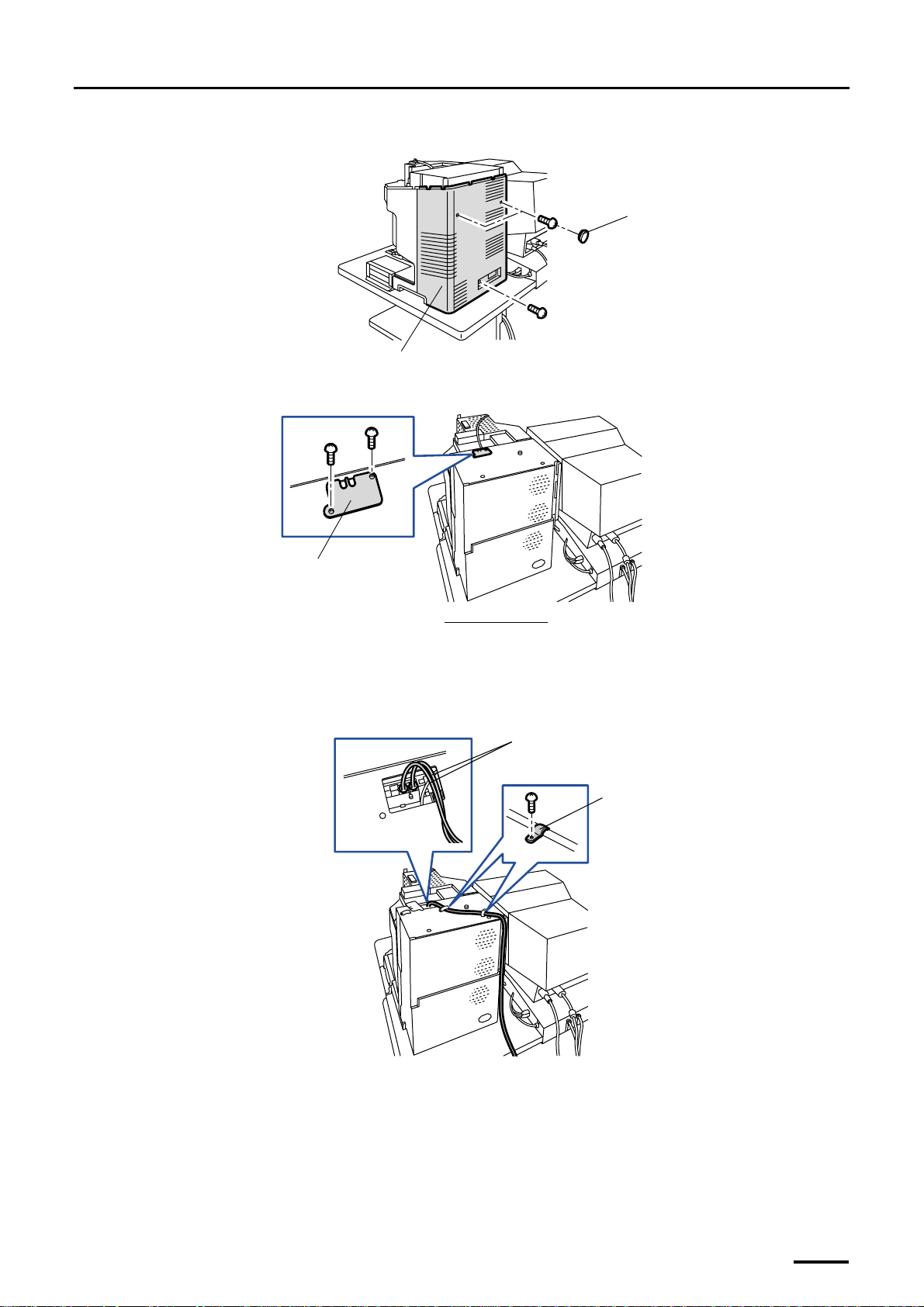
(3) Remove the scanner rear cover. (two caps and three screws)
Cap
Scanner rear cover
(4) Remove the plate. (two screws)
Plate
Viewed from the top
(5) Connect the optical fiber cable to the scanner.
Fix the cables with the clamp along the groove on the back of scanner.
• For details about how to handle the optical fiber cable, refer to ☞Precautions for handling the optical
fiber cable and LVDS cable.
Optical fiber cables
Clamp
G068930
G068931
G075179
49
Page 64
4 Installing the component parts and units
Distributed by: minilablaser.com
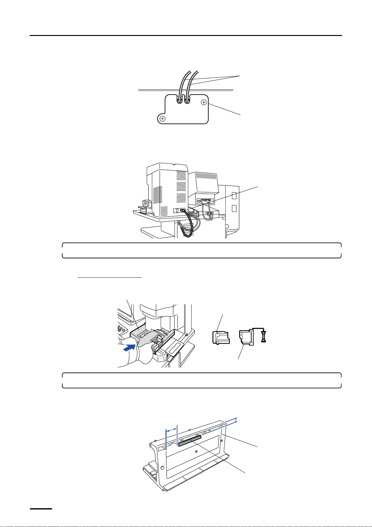
(6) Attach the plate. (two screws)
Attach it with the optical fiber cables through its cutouts.
(7) Reattach the scanner rear cover.
(8) Reattach the scanner top cover.
(9) Connect the power supply cable to the scanner.
Optical fiber cables
Plate
G071511
Power supply cable
3. Attach the film carrier.
This is only for the machine with the optional film carriers.
For the 135/240 AFC-II
The film guide is included in the 135/240 AFC-II. Install the film guide as required.
Film carrier
IX240 film adaptor
135 film loading guide
4. Attach the film cleaner mount.
This is for the machine with the optional film cleaner kit.
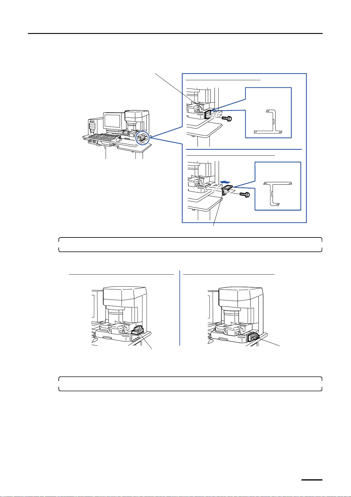
(1) Attach the cushion on the film cleaner mount at the position shown in the figure below.
24 mm
7 mm
G070261
G068907
50
Film cleaner mount
Cushion
G072335
Page 65
4 Installing the component parts and units
Distributed by: minilablaser.com
(2) Attach the film cleaner mount. (two knob screws)
We recommend that you attach the film cleaner mount in the direction shown in the figure.
Film cleaner mount
When you install the film receiving box
Viewed from the
right side
When you do not install the film receiving box
Viewed from the
right side
5. Attach the film cleaner kit.
This is for the machine with the optional film cleaner kit.
After you attach it as below, connect the connector.
When you do not install the optional film receiving box
Film cleaner kit
(option)
6. Attach the film receiving box.
This is for the machine with the optional film receiving box.
Film cleaner mount
When you install the optional film receiving box
G068902
Film cleaner kit
(option)
G070262
51
Page 66
4 Installing the component parts and units
Distributed by: minilablaser.com
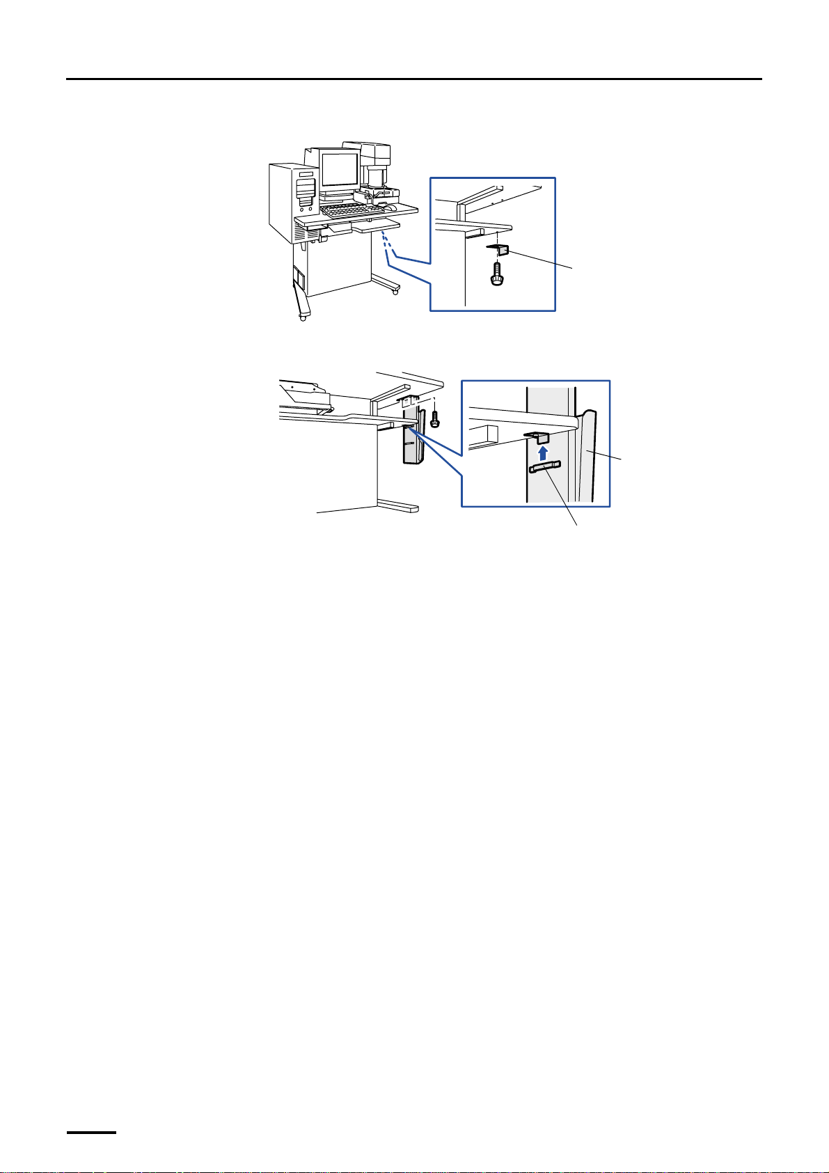
(1) Attach the fixing angle bracket. (one knob screw)
(2) Attach the film receiving box. (two screws)
Attach it aligning the fixing angle bracket to the slot on film receiving box.
Fixing angle bracket
G068896
Film receiving box
This completes installing the component parts and units in the scanner section.
Slot
G068897
52
Page 67
5 Installing the machine and adjusting the level
Distributed by: minilablaser.com
5 Installing the machine and adjusting the level
5.1 Adjusting the level of paper processor section
1. Prepare to move the paper processor section and the printer section.
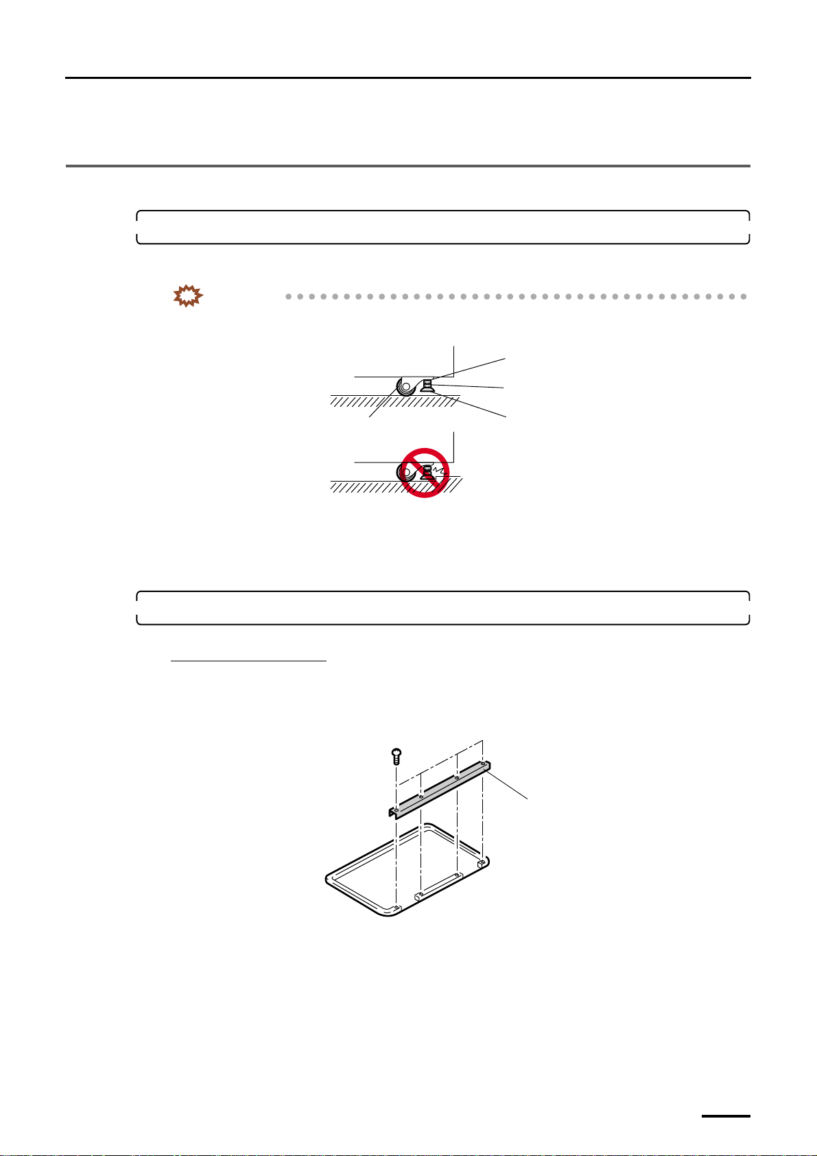
Raise the jack bolts (four for paper processor section, four for printer section) completely so that the machine can be
moved.
IMPORTANT
• Be sure to raise the jack bolts to the uppermost position before moving. If the jack bolts hit any steps
or protrusions during relocation, they may be bent.
Lock nut
Adjusting nut
Castor
Jack bolt
• Move the machine on a flat floor to prevent the castors from being overloaded.
• When moving the machine over a long distance, lift it.
• Hold the bottom frame of the machine when lifting.
• Do not force to the covers.
2. Move the paper processor section to the location intended for installation.
When a floor tray is used:
When an optional floor tray is used, follow the procedure below.
(1) Place the floor tray in the position where the paper processor is to be installed.
(2) Remove the removable channel. (four screws)
Removable channel
G068858
(3) Put the paper processor on the floor tray.
Attach the removable channel after the printer was put on the floor tray.
G071466
53
Page 68
5 Installing the machine and adjusting the level
Distributed by: minilablaser.com
3. Lower the jack bolts and fix the paper processor section at the location for installation.
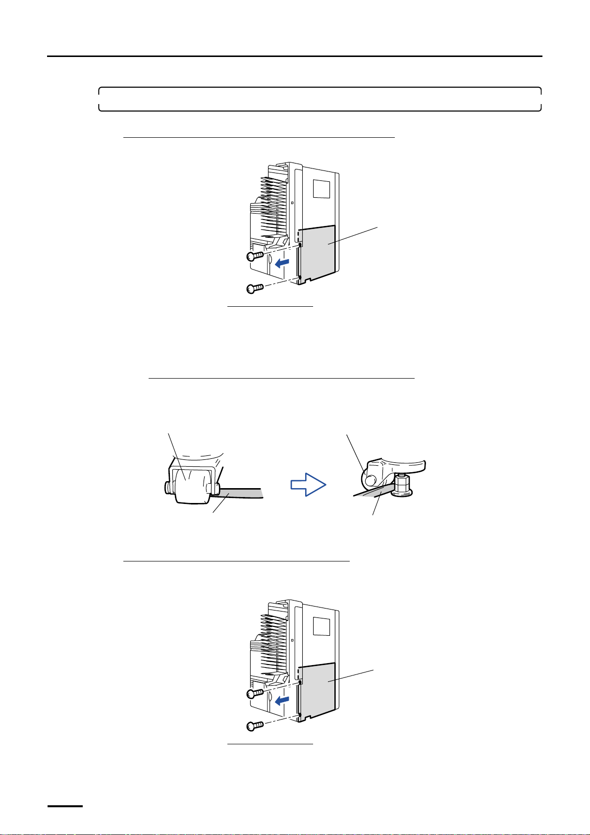
When you install the machine at a place except for the corner:
(1) Remove the processor rear cover. (two screws)
Viewed from the right side
(2) Lower the jack bolts by turning the adjusting nuts manually.
When you can no longer turn the nuts by hand, use the utility pliers to turn them until the castors come off
the floor.
Processor rear cover
G070271
If the jack bolts cannot be lowered due to the castor position:
The direction of a castor placed on the hard floor such as concrete floor can be changed with your hands.
To change the direction of a castor placed on the soft floor (including the thick carpet), insert a rod such as
the pliers grip as shown in the illustration and turn it.
Castor
Utility pliers grip
Castor
Utility pliers grip
G068859
When you install the machine in the corner of room:
If there is not enough space at the back or right side of the paper processor section, follow the procedure below.
(1) Remove the processor rear cover. (two screws)
54
Processor rear cover
Viewed from the right side
G070271
Page 69
5 Installing the machine and adjusting the level
Distributed by: minilablaser.com
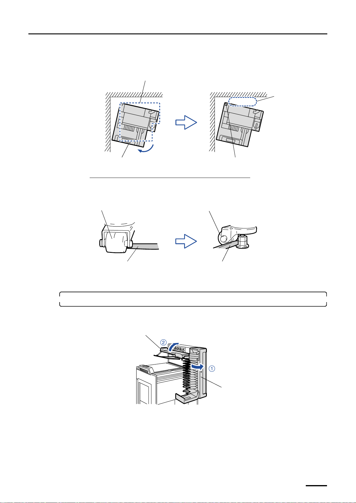
(2) Move the paper processor to the intended installation place and push the printer section connecting side
backward so that you can reach the jack bolts on the paper processor section from the right side.
(3) Lower the jack bolt (part A), and then move the paper processor back to the intended location.
Location intended for installation
Wall
Wall
Reach out your hands
from this side and
lower the jack bolt.
Paper Processor
If the jack bolts cannot be lowered due to the castor position:
The direction of a castor placed on the hard floor such as concrete floor can be changed with your hands.
To change the direction of a castor placed on the soft floor (containing the thick carpet), insert a rod such as
the utility pliers grip between the castor and the floor and turn it as shown in the illustration.
Castor
Utility pliers grip
(4) Lower the other three jack bolts.
4. Adjust the level of the paper processor section.
(1) Open the print sorter unit and raise the print conveyor unit.
Print conveyor unit
Jack bolt (part A)
G068968
Castor
Utility pliers grip
G068859
Print sorter unit
G070263
55
Page 70
5 Installing the machine and adjusting the level
Distributed by: minilablaser.com
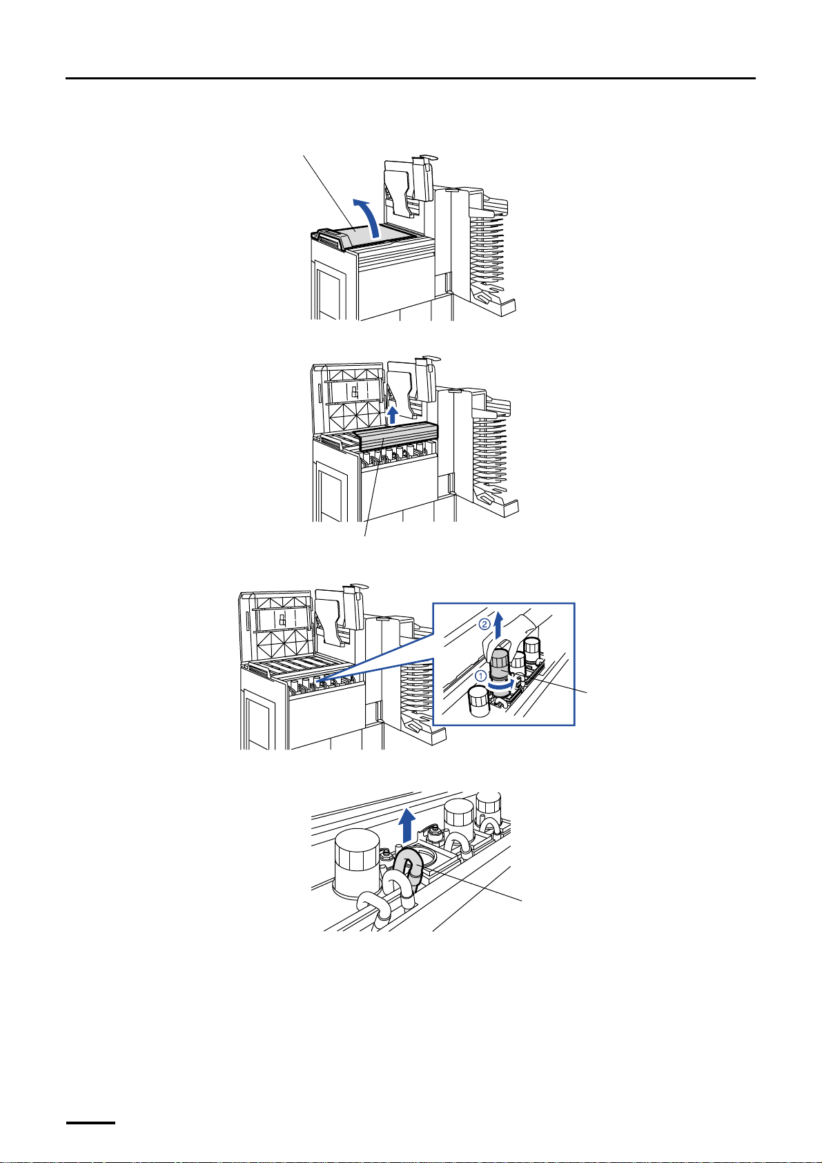
(2) Open the processor top cover.
Processor top cover
(3) Remove the sub-tank top cover.
G068908
Sub-tank top cover
(4) Turn the filter pipe of STB1 in the sub-tank counterclockwise and pull it out.
Filter pipe
(5) Remove the pipe of STB1-W.
STB1-W pipe
G070264
G070265
G068942
56
Page 71
5 Installing the machine and adjusting the level
Distributed by: minilablaser.com
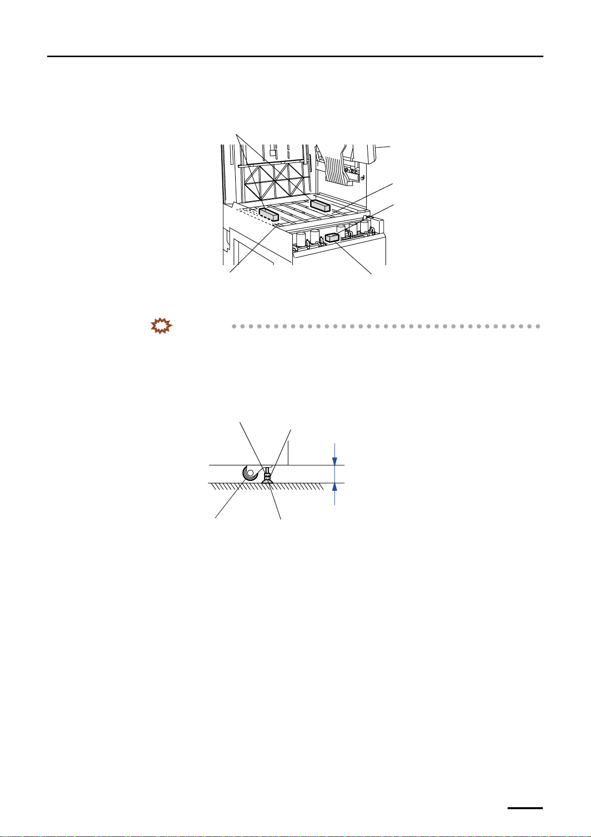
(6) Place the levels at the position shown in the figure below to check the level of the machine at three
points.
Levels
(Check the front and rear levels.)
Upper guide (No.6)
Remove the filter pipe and the refilling
water pipe of the sub-tank for STB1, and
put the level there.
Upper guide (No.2)
Level
(Check the left and right levels.)
(7) If the machine is not leveled, turn the adjusting nut of the jack bolt to adjust it.
IMPORTANT
• If the machine sits unevenly on the floor (difference: 10 mm or more), place a plate or the like
under the jack bolts to level the machine.
• Check that each jack bolt is securely supporting the machine (the castors must not touch the
floor).
• To prevent the jack bolt slipping off, the distance between the bottom frame of the machine
and the floor should be 60 mm or less.
Lock nut
Adjusting nut
Within 60 mm
Castor
• Pay attention to these important points also when adjusting the level of the printer in the next
step.
Jack bolt
G070266
G068862
(8) After the level adjustment, lock four jack bolts with the lock nuts.
(9) Remove the levels.
(10) Reattach the filter pipe and refilling water pipe.
(11) Reattach the sub-tank top cover.
This completes adjusting the level of paper processor section.
57
Page 72
5 Installing the machine and adjusting the level
Distributed by: minilablaser.com
5.2 Connecting the printer and the paper processor and adjusting the level
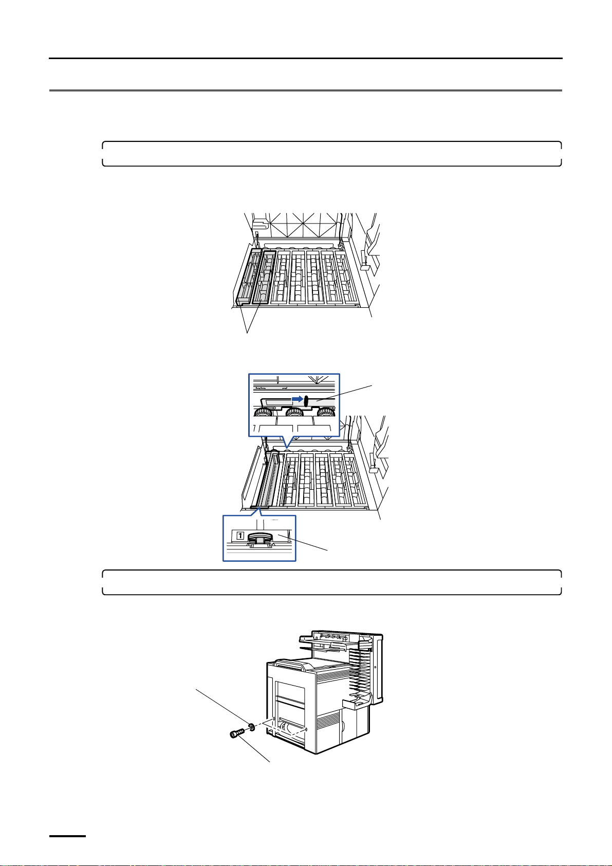
1. Remove the upper guides (Nos. 1 and 2) and the processing rack (No. 1).
(1) Remove the upper guides (Nos. 1 and 2).
Attach the upper guides after checking the processing solution level.
Upper guides
(2) Move the rack stoppers to release the lock and remove the processing rack (No. 1).
Rack stopper
Rack stopper
2. Prepare the bolts for connection and the like.
(1) Remove the two socket head bolts for connection and two washers from the paper processor.
G068909
G068910
58
Washer
Socket head bolt
G071467
Page 73
5 Installing the machine and adjusting the level
Distributed by: minilablaser.com
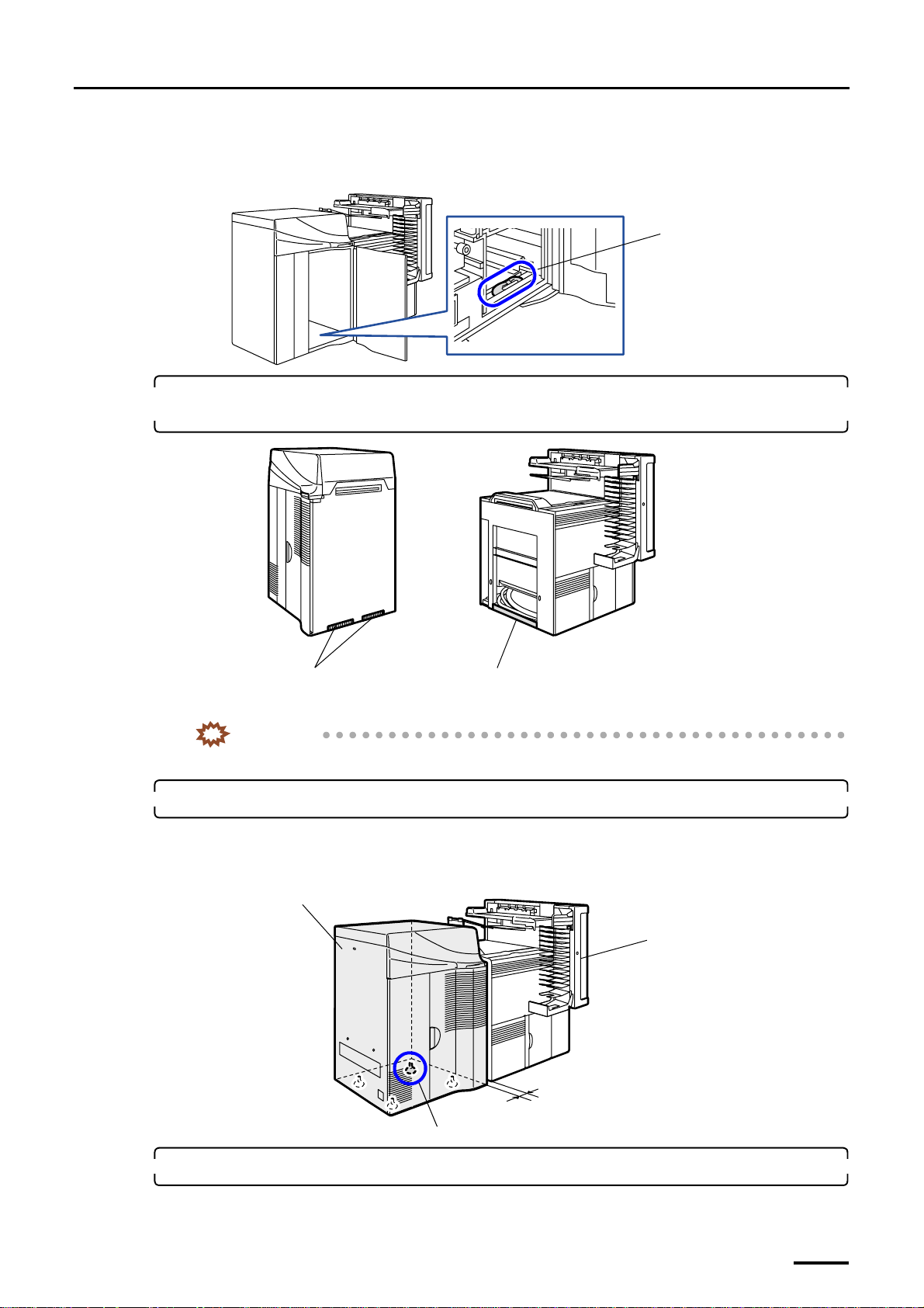
(2) Take one screw for connection, two hex. head bolts and two washers out of the bag that contained the
magazine deck unit lock levers.
You can find the bag containing the screw, bolts and washers at the position shown in the figure below.
Bag containing the screw, bolts
and washers
G072106
3. Wipe off dirt on the copper plate for ground the printer and that for ground the paper processor
using a rag.
Copper plates for ground
Area to be contacted with copper plates for
ground
IMPORTANT
• If the ground part is not clean, the ground resistance may be strong due to poor contact.
4. Place the printer next to the paper processor.
Place the printer at the position 3 to 5 cm away from the the paper processor.
If there is not enough space at the back of printer, lower the jack bolt of part A to the castor movable position in
advance.
Printer
Paper Processor
3 cm to 5 cm
Part A
G068960
G070270
5. Remove the covers of the paper processor.
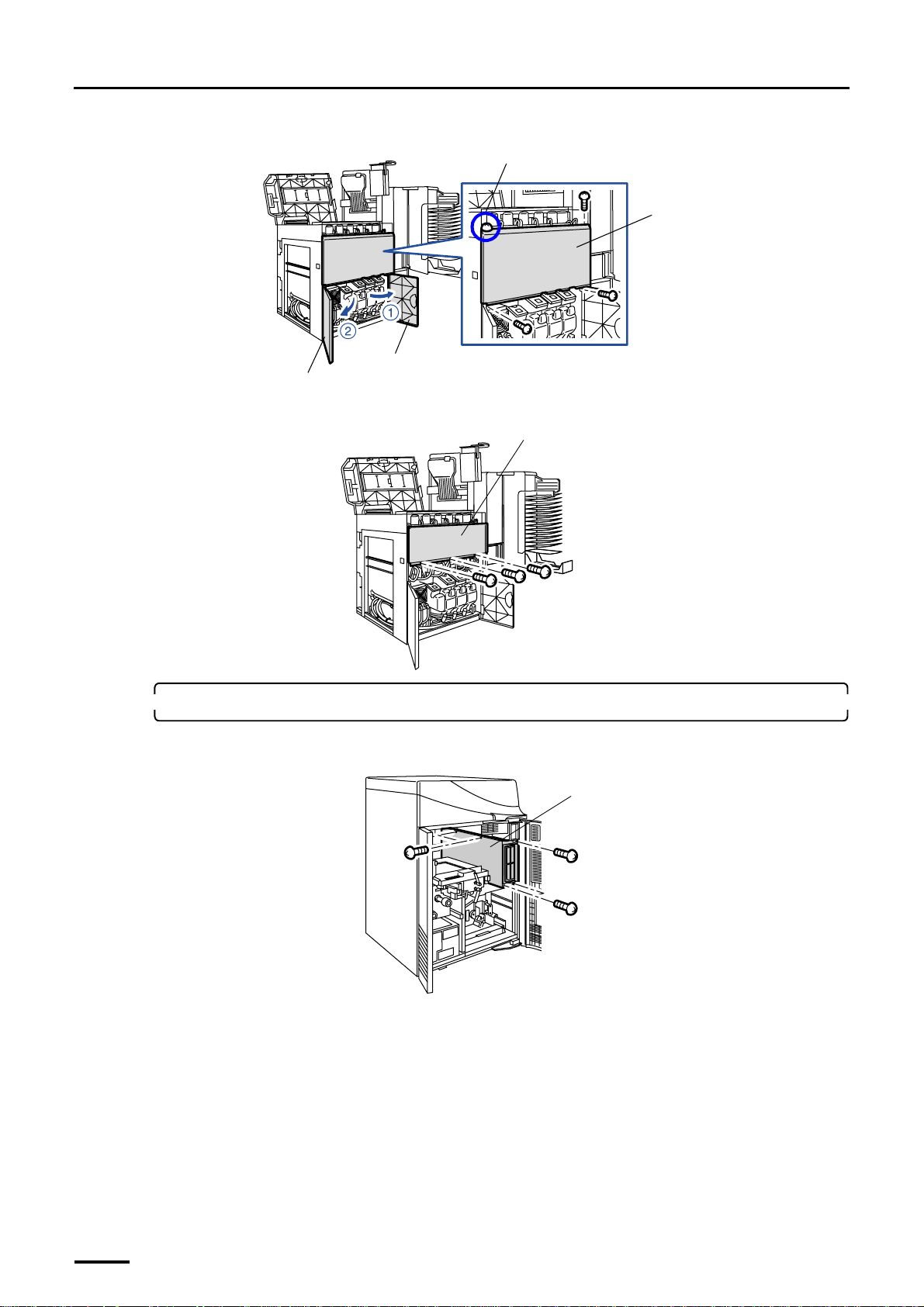
(1) Open processor doors 1 and 2.
59
Page 74
5 Installing the machine and adjusting the level
Distributed by: minilablaser.com
(2) Remove processor cover 1. (Loosen one of the four screws.)
Processor door 2
Processor door 1
(3) Remove the wiring duct cover. (three screws)
Loosen this screw.
Processor cover 1
G068943
Wiring duct cover
6. Wire the connection cables and optical fiber cables in the printer section.
(1) Remove the wiring cover from the printer section. (five screws)
Wiring cover
G068944
G073038
60
Page 75
5 Installing the machine and adjusting the level
Distributed by: minilablaser.com
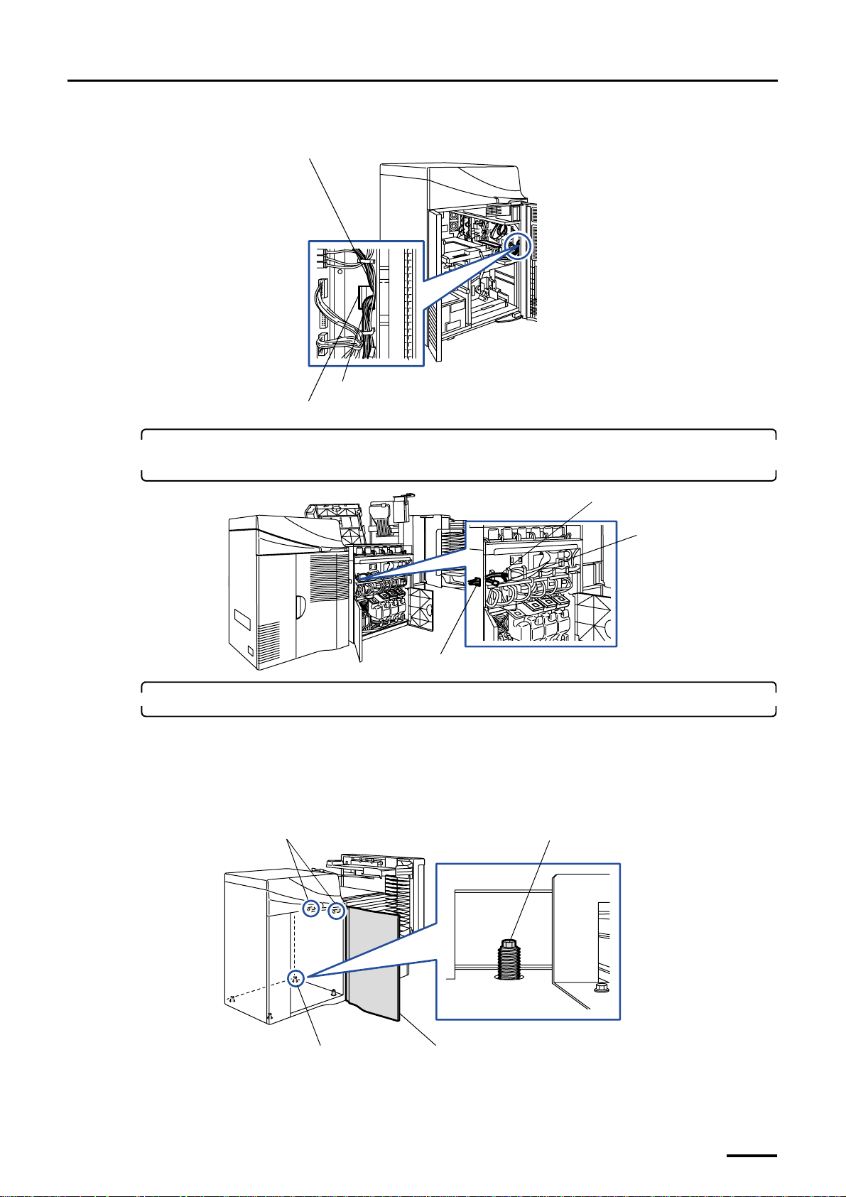
(2) Pass the connection cable (J355) and the optical fiber cables through the square hole.
Optical fiber cable
Connection cable
Square hole
G073039
7. Pass the connection cable and the optical fiber cables from the printer through square hole 1
on the paper processor.
Optical fiber cable
Printer connection
cable (J355)
Square hole 1
8. Connect the printer to the paper processor.
(1) Open printer door 2.
(2) Adjust the jack bolts of the printer so that the regulation pins fit the pin holes of the paper processor.
If there is not enough space at the back of the printer, adjust the jack bolt (part A) from the inside of the
printer.
Regulation pins
Jack bolt
G072115
Part A
Printer door 2
G068971
61
Page 76
5 Installing the machine and adjusting the level
Distributed by: minilablaser.com
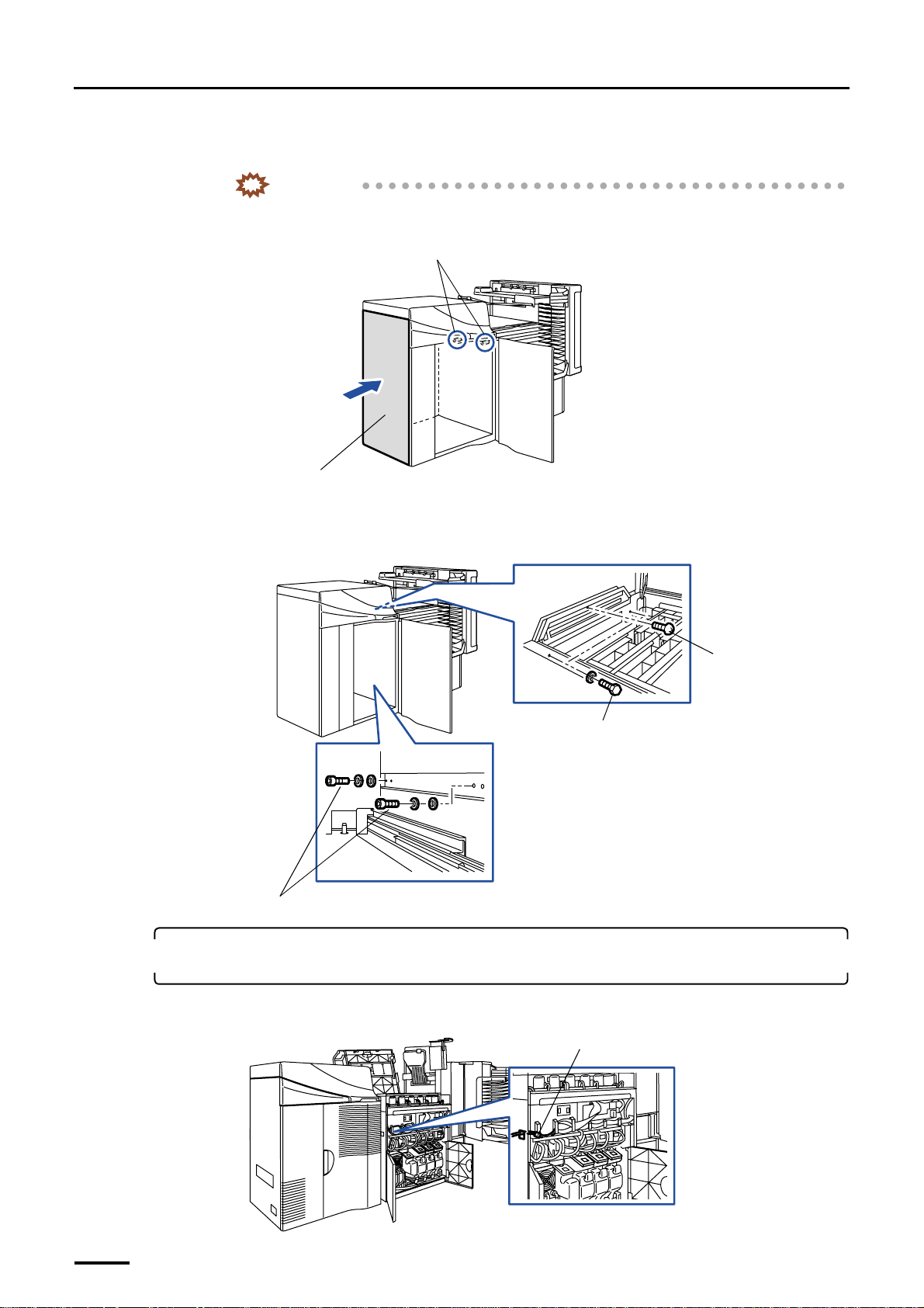
(3) Push the left side of the printer (gray part in the illustration) to insert two regulation pins into the paper
processor.
IMPORTANT
• Do not connect the printer to the paper processor while the cables are slack between them.
The cable may be pinched and broken.
Regulation pins
Left side
(4) Connect the printer and processor temporarily.
From the processor, tighten the one screw, two hex. head bolts and two washers temporarily.
From the printer, tighten the two socket head bolts and four washers temporarily.
Bolts and washers
Socket head bolts and washers
G070272
Screw
G068950
9. Connect the printer connection cable and the optical fiber cables to their counterparts in the
paper processor.
(1) Connect the printer connection cables.
62
J/P355
G072114
Page 77
5 Installing the machine and adjusting the level
Distributed by: minilablaser.com
(2) Pass the optical fiber cables through square hole 2.
Fix the optical fiber cables with the clamps not to make them loose.
Clamps
Optical fiber cable
(3) Connect the optical fiber cables to the processor control PCB.
Fix the optical fiber cables with two clamps.
Square hole 2
G068945
• For details about how to handle the optical fiber cable, refer to
fiber cable and LVDS cable.
Square hole 2
Viewed from the right side
Optical fiber cables
(4) Reattach the wiring cover and processor cover 1.
IMPORTANT
• Do not allow the cables to be pinched by the wiring duct cover.
(5) Reattach the wiring duct cover in the printer section.
☞Precautions for handling the optical
Clamps
Processor control PCB
J/P518 (OUT)
J/P517 (IN)
G068970
63
Page 78
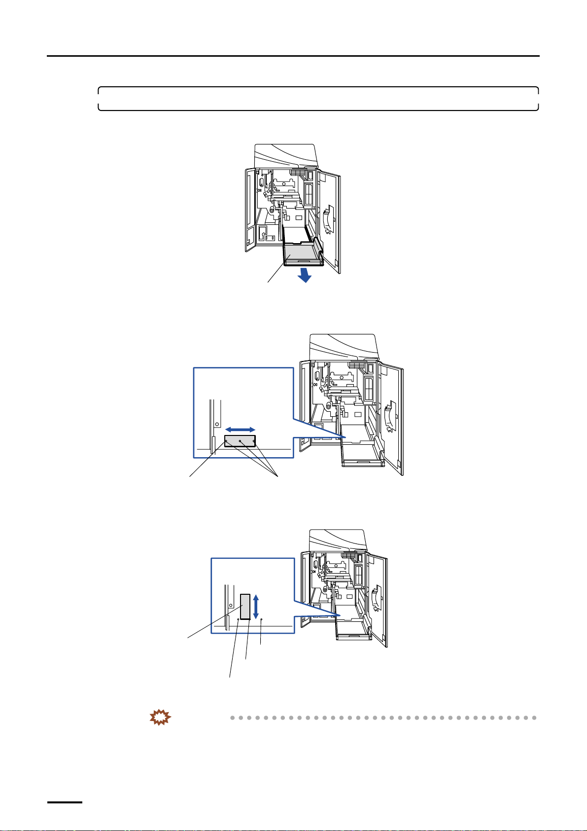
5 Installing the machine and adjusting the level
Distributed by: minilablaser.com
10. Adjust the level of the printer.
(1) Pull out magazine deck unit C.
Magazine deck unit C
(2) Place the level at the position shown below to check the machine level in the arrow direction.
Place the level in the center of the three positioning marks.
Viewed from above
Level
Positioning marks
(3) Place the level at the position shown below to check the machine level in the arrow direction.
Align the edge of level to the center of positioning marks.
Viewed from above
G070273
G068951
(4) If the machine is not leveled, turn the adjusting nut of the jack bolt to adjust it.
• Adjust the level of the printer section securely. If the level is not adjusted accurately, a paper
• If the machine sits unevenly on the floor (difference: 10 mm or more), place a plate or the like
64
Level
Positioning mark
Positioning mark
Center of positioning marks
IMPORTANT
may zigzag.
under the jack bolts to level the machine.
G068972
Page 79
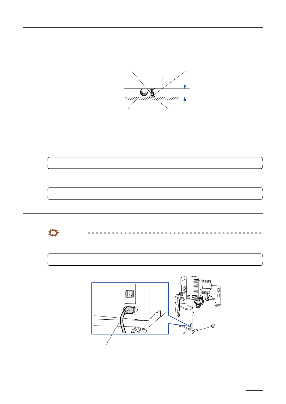
5 Installing the machine and adjusting the level
Distributed by: minilablaser.com
• Check that each jack bolt is securely supporting the machine (the castors must not touch the
floor).
• To prevent the jack bolt slipping off, the distance between the bottom frame of the machine
and the floor should be 60 mm or less.
Lock nut
Adjusting nut
Within 60 mm
Castor
Jack bolt
G068862
(5) After the level adjustment, lock the jack bolts with the lock nuts.
(6) Tighten the bolts up for connecting the printer and the processor securely.
(7) Remove the levels.
(8) Reattach the paper magazine to the magazine deck unit and put it away.
11. Attach the triple magazine.
This is for the machine with the optional triple magazine.
• For details about how to attach the triple magazine, refer to
☞Installing the optional triple magazine.
12. Close printer doors 1 and 2.
This completes adjusting the level of printer and paper processor.
5.3 Connecting the desk section and the printer section (power cable)
IMPORTANT
• When you connect the power cable, do not pull it by force and do not give extra pressure to the cable.
• Wire the cables with a wiring duct to prevent the cables from stepping on or getting caught.
1. Connect the power cable from the printer section to the input section.
Example: For the machine with the scanner
Power supply cable (J/P161)
This completes connecting the desk section to the printer section (power cable).
G068938
65
Page 80
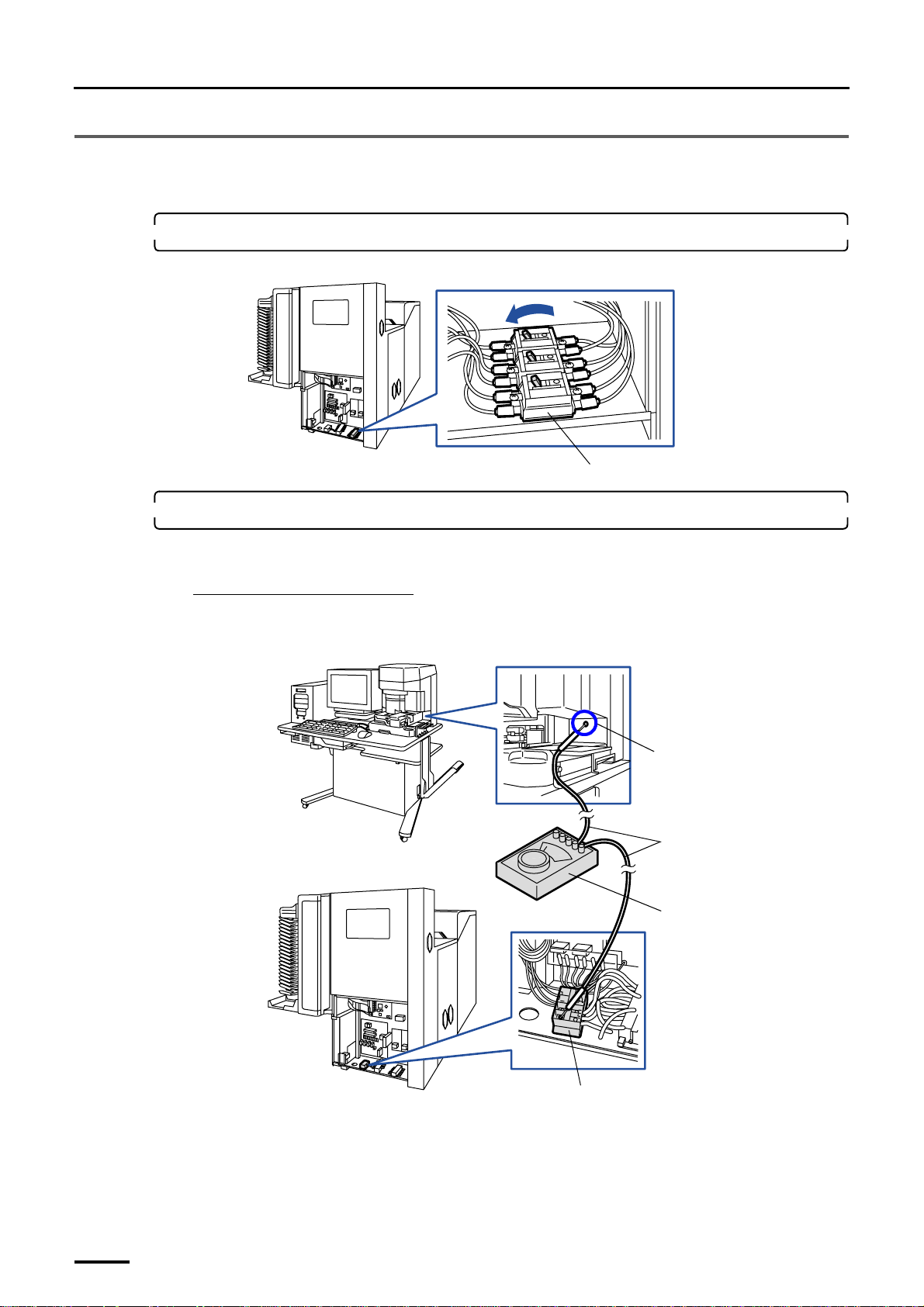
5 Installing the machine and adjusting the level
Distributed by: minilablaser.com
5.4 Measuring the resistance
Measure the resistance between the machines with a voltmeter.
1. Make sure that the earth leakage circuit breakers are turned ON.
If not, turn it ON.
ON
OFF
Earth leakage circuit breaker
2. Measure the resistance between the measuring points.
When the cable of the voltmeter is too short to reach the measuring points of each machine, use an extension cable
(W407756-01) which is included in the service personnel tool.
When using the extension cable
Measure the resistance of the extension cable and take notes of it.
For the machine with the scanner
Input Section
Screw
G070274
66
Paper processor section
*1. Use the extension cable if necessary.
Terminal strips
Measuring cables
Voltmeter
*1
G068954
Page 81
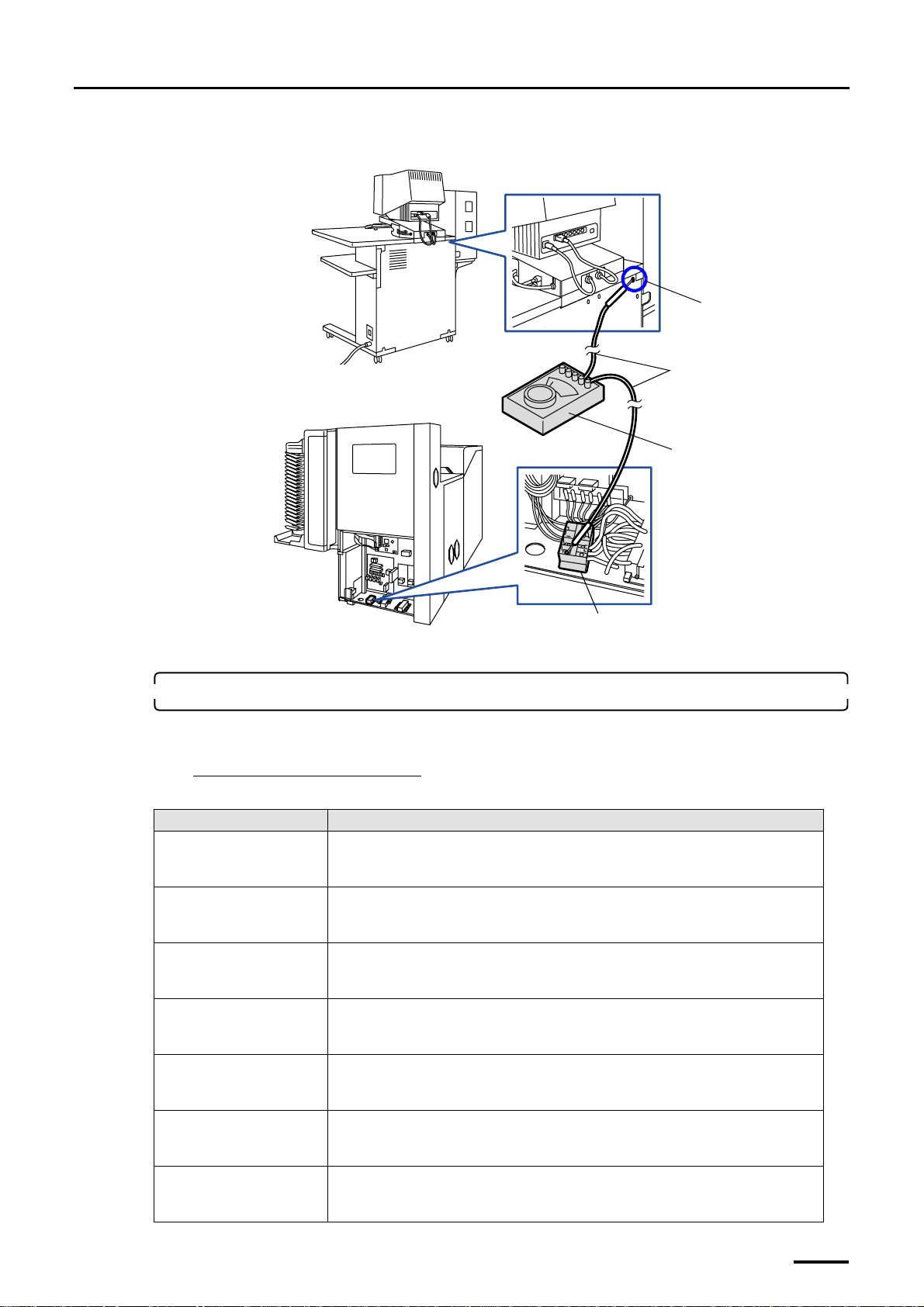
For the machine without the scanner
Distributed by: minilablaser.com
Desk section
5 Installing the machine and adjusting the level
Screw
Measuring cables
Paper processor section
Voltmeter
Terminal strips
*1. Use the extension cable if necessary.
*1
3. Check that the measured value is 1 Ω or less.
When you use the extension cable, subtract the resistance of the cable that taken notes in the previous step, and then
check the value.
If the resistance is more than 1 Ω
If the resistance is more than 1 Ω, check the following items, take the proper action and measure it again.
G070275
Failure points Corrective action
Voltmeter failure Make short-circuit the measuring points of the voltmeter and check that the resistance
becomes 0.0 Ω. If it does not indicate 0.0 Ω, the voltmeter may malfunction. Measure
the resistance with a normal voltmeter.
Poor contact of a cable
between the scanner section
and desk section
*1
A cable between the scanner
section and desk section is
*1
broken.
Poor contact of a cable
between the desk section and
Check that the cables between scanner section and desk section are connected correctly.
If not, connect them correctly.
Check if the cable is not broken. If a cable is broken, replace it.
Check that the cables between the desk section and printer section are connected
correctly. If not, connect them correctly.
printer section
A cable between the desk
Check if the cable is not broken. If a cable is broken, replace it.
section and printer section is
broken.
Connection failure between
the paper processor section
and printer section
The copper plate for ground
in the printer lower section is
unattached or damaged.
Check that the copper plate for ground which is located in the printer lower section
contacts with the frame of the paper processor.
If they do not contact properly, adjust the position of the printer or paper processor.
Check that the copper plate is damaged or removed from the frame in the printer lower
section. If it is removed, attach it to the proper location. If the plate is damaged, replace
it.
67
Page 82
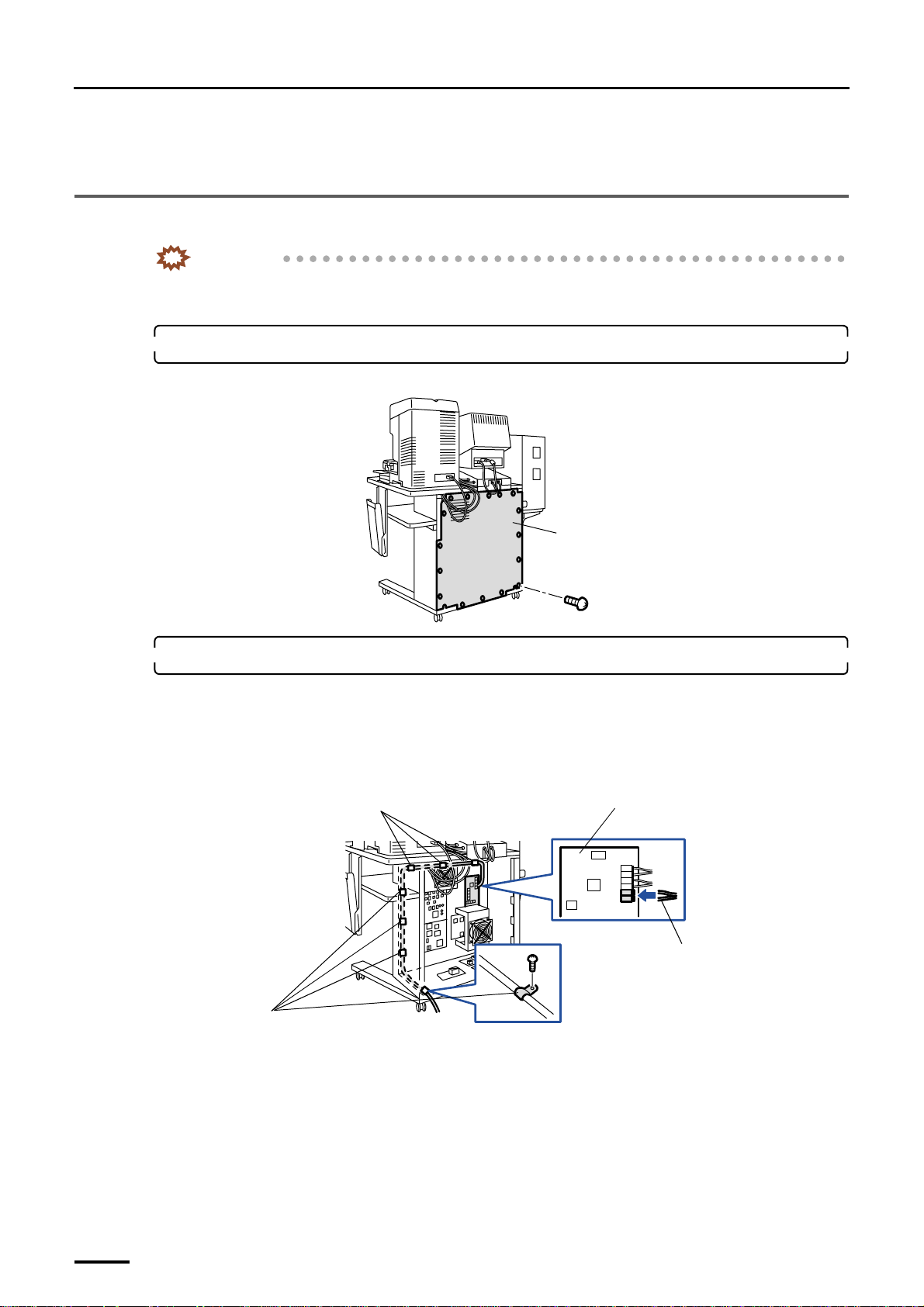
5 Installing the machine and adjusting the level
Distributed by: minilablaser.com
*1. Only when the scanner is equipped.
This completes measuring the resistance.
5.5 Connecting the desk section and the printer section (signal cable)
IMPORTANT
• When you connect each cable, do not pull it by force and do not give extra pressure to the cable.
• Wire the cables with a wiring duct to prevent the cables from stepping on or getting caught.
1. Remove the rear cover from the input section. (16 screws)
Example: For the machine with the scanner
Rear cover
2. Connect the cables from the printer section to the input section.
(1) Connect the optical fiber cables to the D-ICE control PCB.
Fix the optical fiber cables with seven clamps not to make them loose.
• For details about how to handle the optical fiber cable, refer to
fiber cable and LVDS cable.
Clamps
G068952
☞Precautions for handling the optical
D-ICE control PCB
Optical fiber cable
(2) Connect the connector of LVDS cable to the image processing PCB.
Fix the LVDS cable with two FG clamps and three clamps not to make them loose.
• For details about how to handle the LVDS cable, refer to ☞Precautions for handling the optical fiber
68
Clamps
G070276
cable and LVDS cable.
Page 83
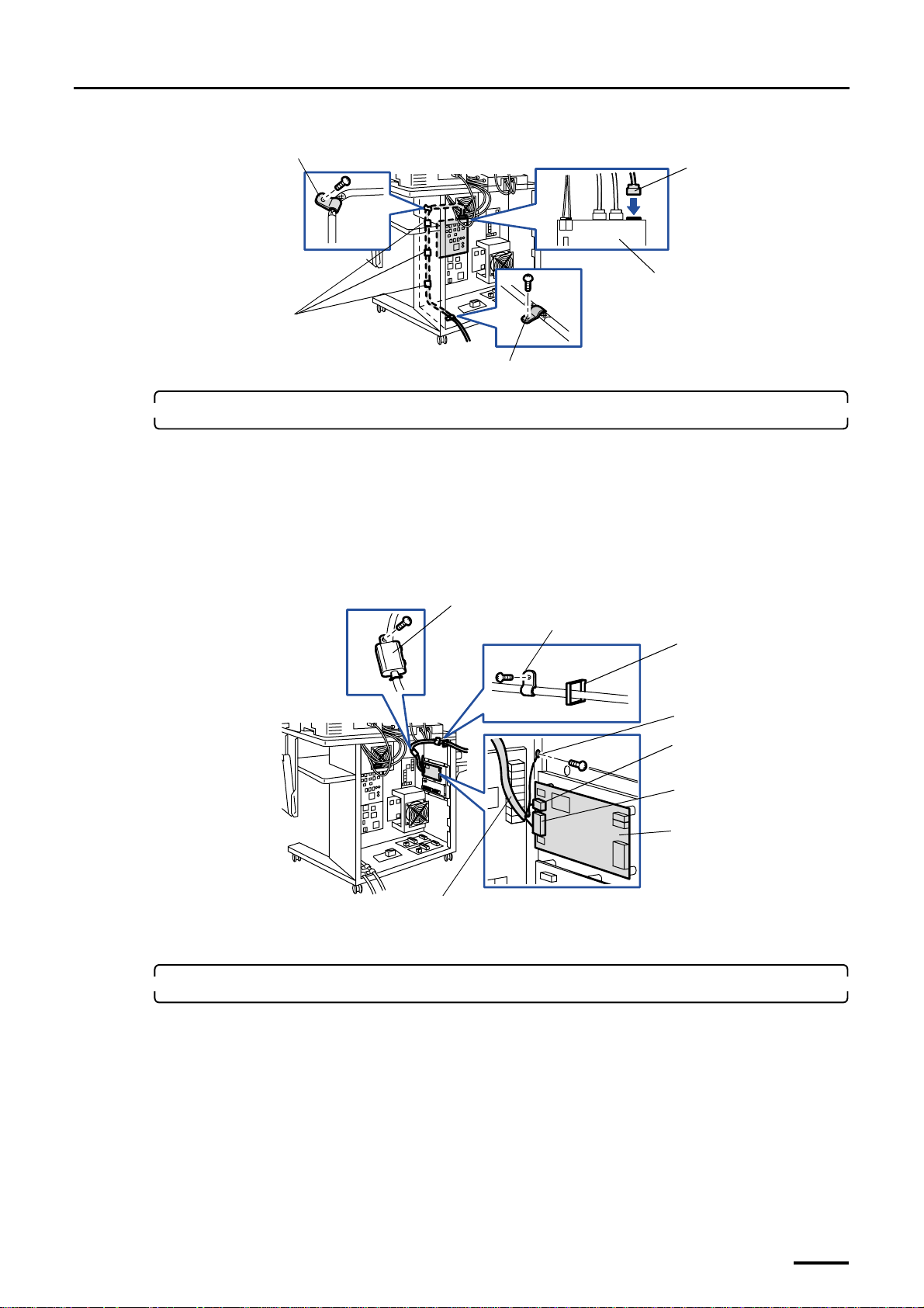
FG clamp
Distributed by: minilablaser.com
Clamps
5 Installing the machine and adjusting the level
LVDS cable (J455)
Image processing PCB
FG clamp
3. Connect the cables from the optional Pricing Unit to the input section.
This is for the machine with the optional Pricing Unit.
(1) Connect the cable from the Pricing Unit to the PU control PCB.
(2) Connect the ground wire from the Pricing Unit to the desk section. (one screw)
(3) Fix the cables that are connected to the Pricing Unit with the clamp (one screw) and clamps (wire
saddle).
(4) Attach the ferrite core. (one screw)
Ferrite core
Clamp
Clamp
(wire saddle)
Ground wire
J/P305
J/P304
G070277
Cable connected to the Pricing Unit
4. Reattach the rear cover to the input section.
Attach it aligning each cable to the cutouts on the rear cover.
PU control PCB
G070289
69
Page 84
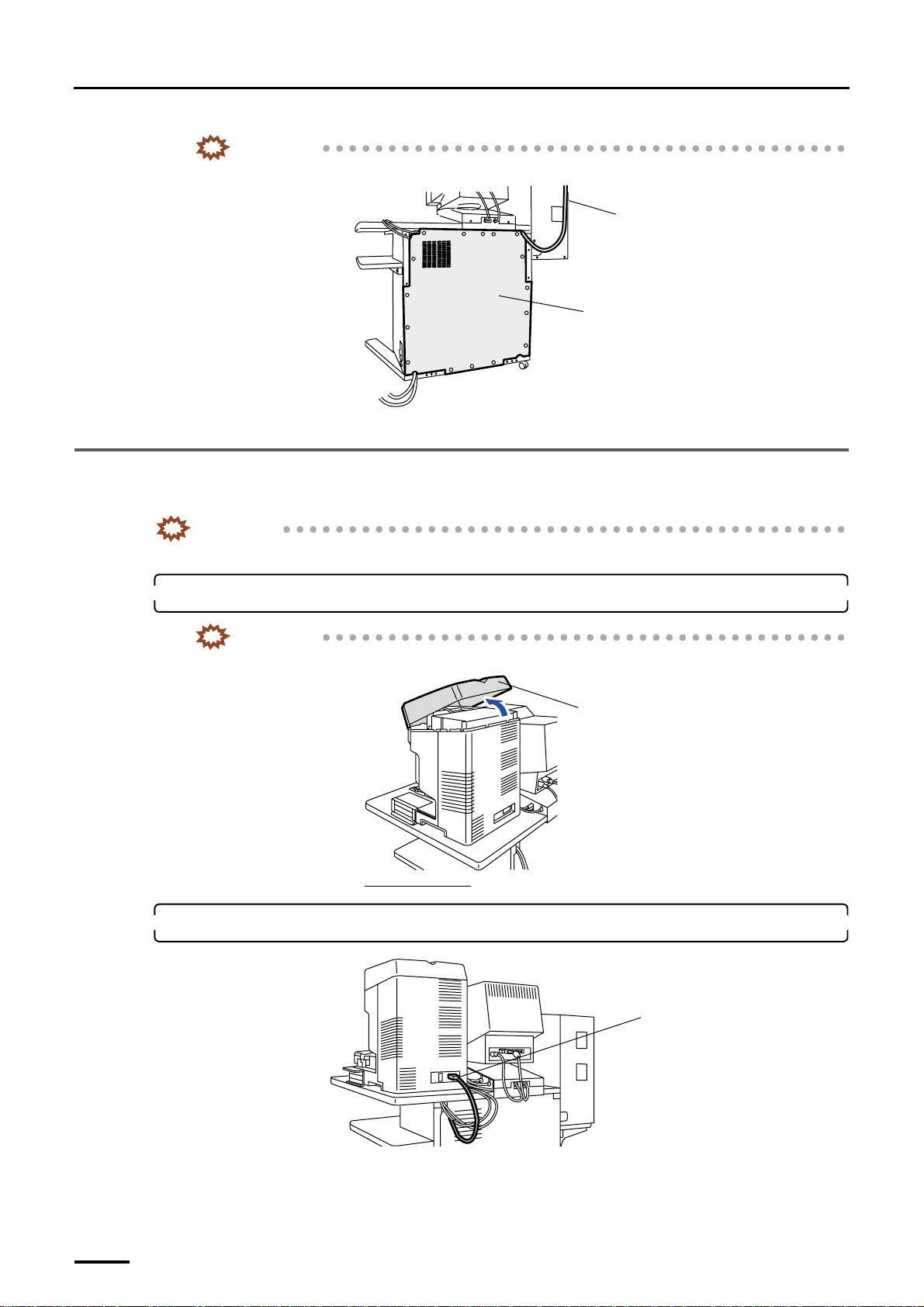
5 Installing the machine and adjusting the level
Distributed by: minilablaser.com
IMPORTANT
• Do not allow each cable to be pinched by the input section rear cover.
Cable connected to the Pricing
Unit
Rear cover
This completes connecting the desk section to the printer section (signal cable).
5.6 Connecting the scanner section and the desk section (signal cable)
This is for the machine with the scanner.
IMPORTANT
• When you connect each cable, do not pull it by force and do not give extra pressure to the cable.
G070293
1. Remove the scanner top cover.
IMPORTANT
• You cannot remove the scanner top cover from the front side. Remove it from the back.
Scanner top cover
Viewed from the rear
2. Remove the power supply cable.
Power supply cable
G068929
70
G070261
Page 85
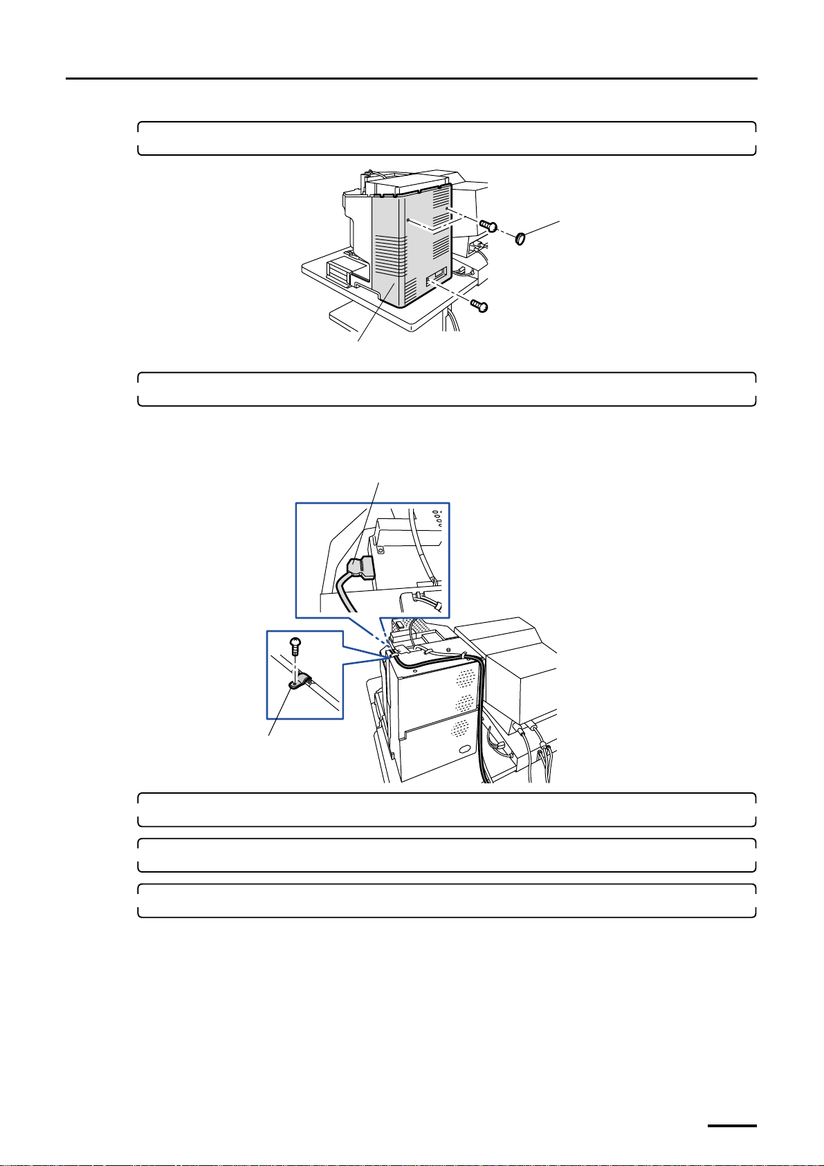
5 Installing the machine and adjusting the level
Distributed by: minilablaser.com
3. Remove the scanner rear cover. (two caps and three screws)
Cap
Scanner rear cover
4. Connect the LVDS cable to the scanner.
Fix the cables with the FG clamp along the groove on the back of scanner.
• For details about how to handle the LVDS cable, refer to ☞Precautions for handling the optical fiber cable
and LVDS cable.
LVDS cable (J/P60)
FG clamp
G068930
5. Reattach the scanner rear cover.
6. Connect the power cable.
7. Reattach the scanner top cover.
This completes connecting the scanner section to the desk section (signal cable).
G075180
71
Page 86
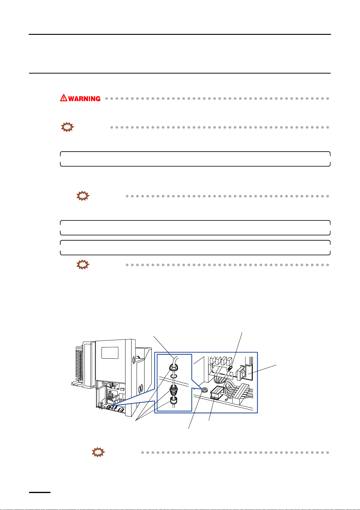
6 Connecting the power supply
Distributed by: minilablaser.com
6 Connecting the power supply
6.1 Connecting the power supply
• It can cause electrical shock.
Before performing the following operation, be sure to turn off the circuit breaker and the main power supply.
IMPORTANT
• Install the circuit breaker for the main power supply in an easily accessible position (close to the machine).
Leave the operation explained in 6 Connecting the power supply to an electric specialist.
1. Confirm the power specification.
The wiring method varies depending on the power specifications.
Check the power specifications indicated on the rating plate (power supply type, voltage, and frequency) before
proceeding with wiring.
IMPORTANT
• Incorrect wiring could cause an electric shock or a fire. Confirm the power specification carefully
before operating.
2. Confirm that the circuit breaker and main power supply are off.
3. Connect the power cable to the terminal strips.
IMPORTANT
• This machine is equipped with a surge protector. When conducting an insulation resistance test,
disconnect the connector on the PCB shown in the figure.
• For USA - Field Wiring connection must meet NEC code for conduit connection.
• For CANADA - Field Wiring connection must meet CEC code for conduit connection.
(1) Draw the cable from the cable opening.
(2) Secure the power cable using the fixings.
Power cable
Connector to be removed when the
insulation resistance test is carried out
(J/P663)
Processor relay PCB
Connect the power cable to the terminal strips referring the following table.
• Tighten the screws on the terminal strips again within 24 through 48 hours.
72
Fixings
IMPORTANT
Terminal strips
Cable opening
G070353
Page 87
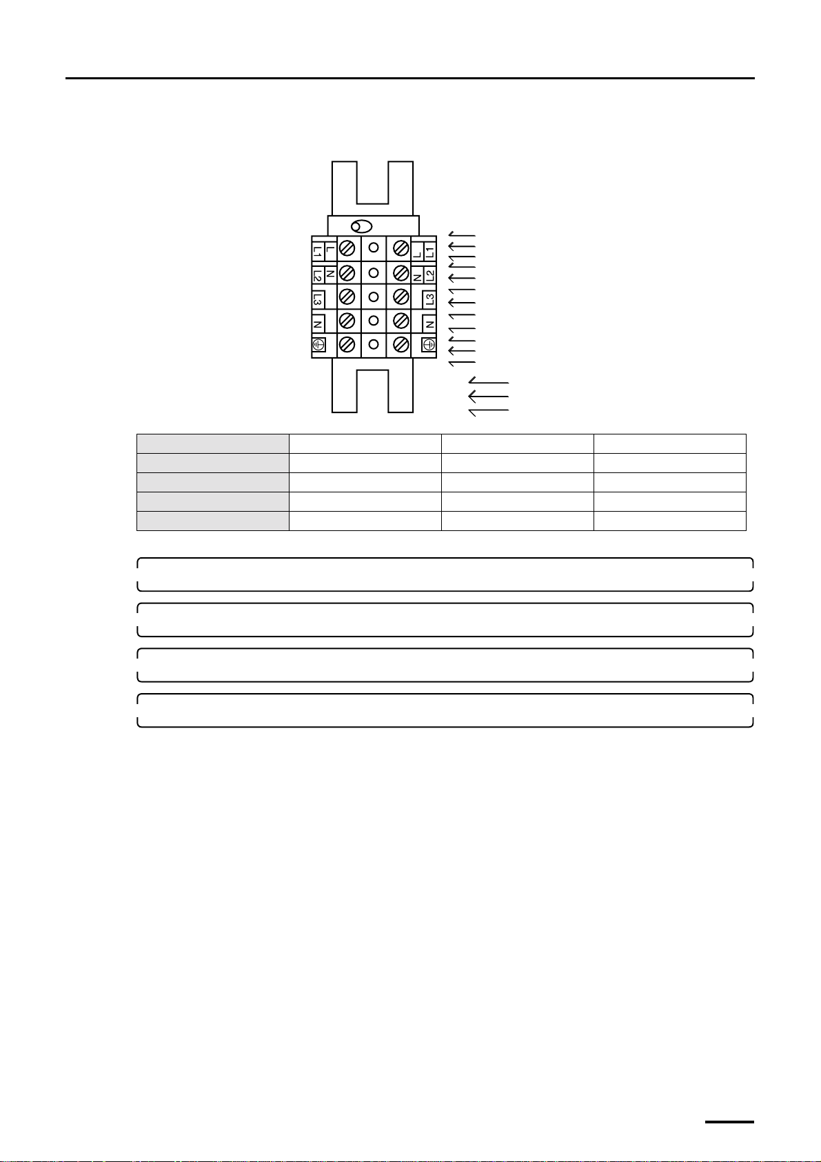
6 Connecting the power supply
Distributed by: minilablaser.com
• The terminal number N differs between single-phase two-wire and three-phase four-wire
power supplies.
L
L1
L1
N
L2
L2
L3
L3
N
GND
GND
GND
Single-phase two-wire
Three-phase three-wire
Three-phase four-wire
Number of phases Single-phase two-wire Three-phase three-wire Three-phase four-wire
Voltage (V) 200 - 240 200 - 240 346 - 415
Cable area AWG8 (8 mm 2 ) AWG10 (5.5 mm 2 ) AWG12 (3.5 mm 2 )
Cable peeling length 11 mm 11 mm 11 mm
Tightening torque 1.5 Nm 1.5 Nm 1.5 Nm
G051424
4. Turn on the main power supply.
5. Insert a voltmeter into the terminal strips and check the voltage.
6. Turn off the main power supply.
7. Reattach the processor rear cover. (two screws)
This completes connecting the power supply.
73
Page 88
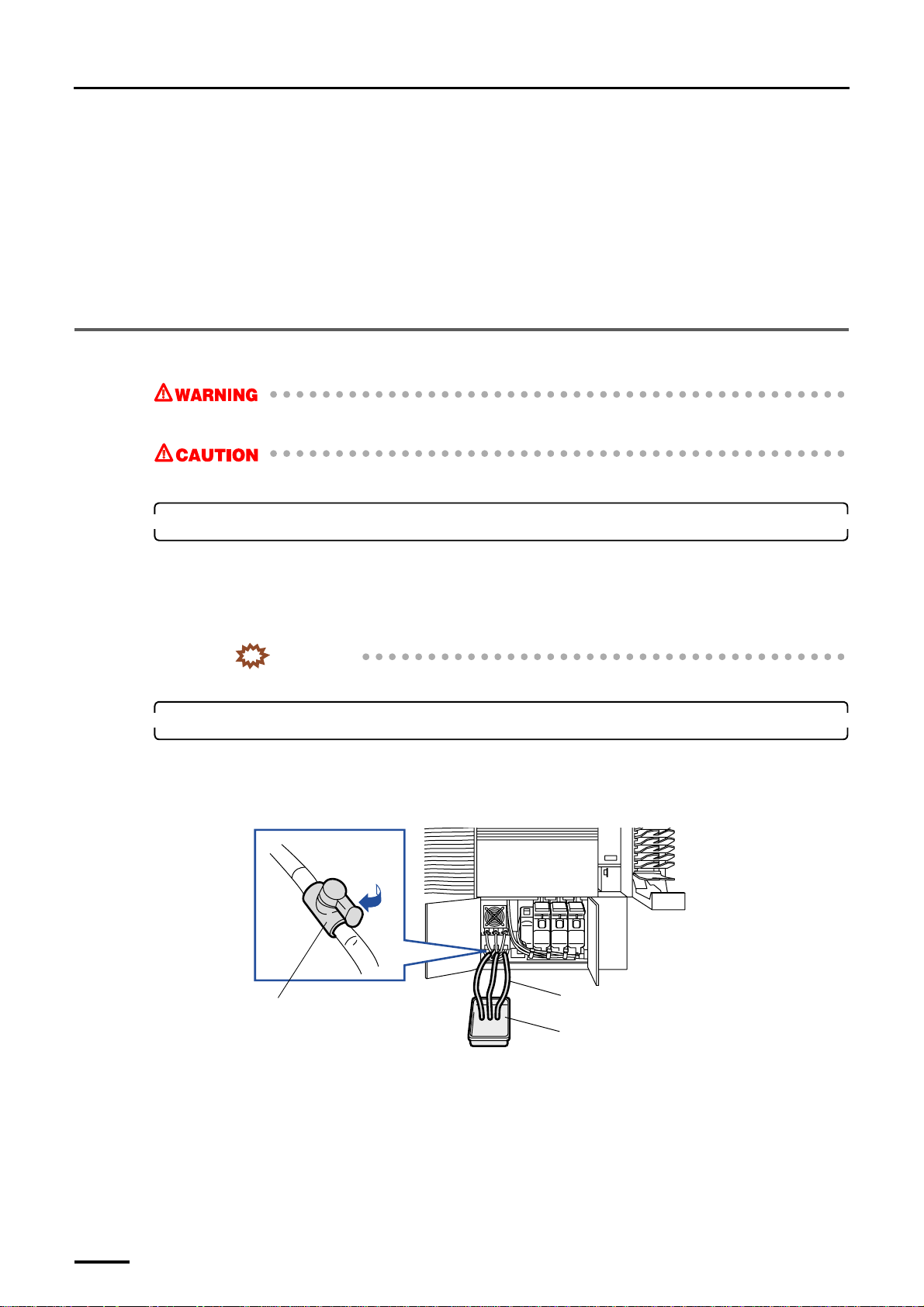
7 Filling the tanks with processing and replenishment solutions
Distributed by: minilablaser.com
7 Filling the tanks with processing and replenishment
solutions
The processing and replenishment solutions vary depending on the specification.
Make sure the machine specification before start working.
• For the normal specification, refer to
• For SM specification, refer to ☞7.2 Filling the tanks with processing solutions and attaching the replenishment
packages [SM].
7.1 Filling the tanks with processing and replenishment solutions [N]
• Processing solution can cause eye irritation. Wear safety goggles.
• Processing solution can cause skin irritation. Wear rubber gloves and clothing for work wear.
1. Prepare to pour the processing solution.
☞7.1 Filling the tanks with processing and replenishment solutions [N].
(1) Pour water and chemical solution into the other container following the instructions in the Processing
Manual or that supplied with the chemical solution, and mix them. (For your convenience, use the
mixing tank.)
For tank capacity, refer to the Processor information in the Specifications.
IMPORTANT
• Use water at the temperature specified by the manufacturers of the chemical solution.
2. Wash the processing tanks.
Wash all the tanks according to the procedure below.
(1) Connect the hose to the drain valve of each processing solution tank, and put the other end of the hose
in a drain or a container.
Hose
Drain valve
Container
(2) Open the drain valve of each processing solution tank, wash the inside of the tanks, and then close the
drain valves.
G068925
(3) Fill the processing solution tanks with water up to the overflow port, and then ensure that there is no
water leakage.
(4) If there is no water leakage, open the drain valve to discharge the water from the tank.
(5) Make sure that the processing solution tanks are completely empty, and then close the drain valves.
(6) Wash each tank in the same procedure.
74
Page 89
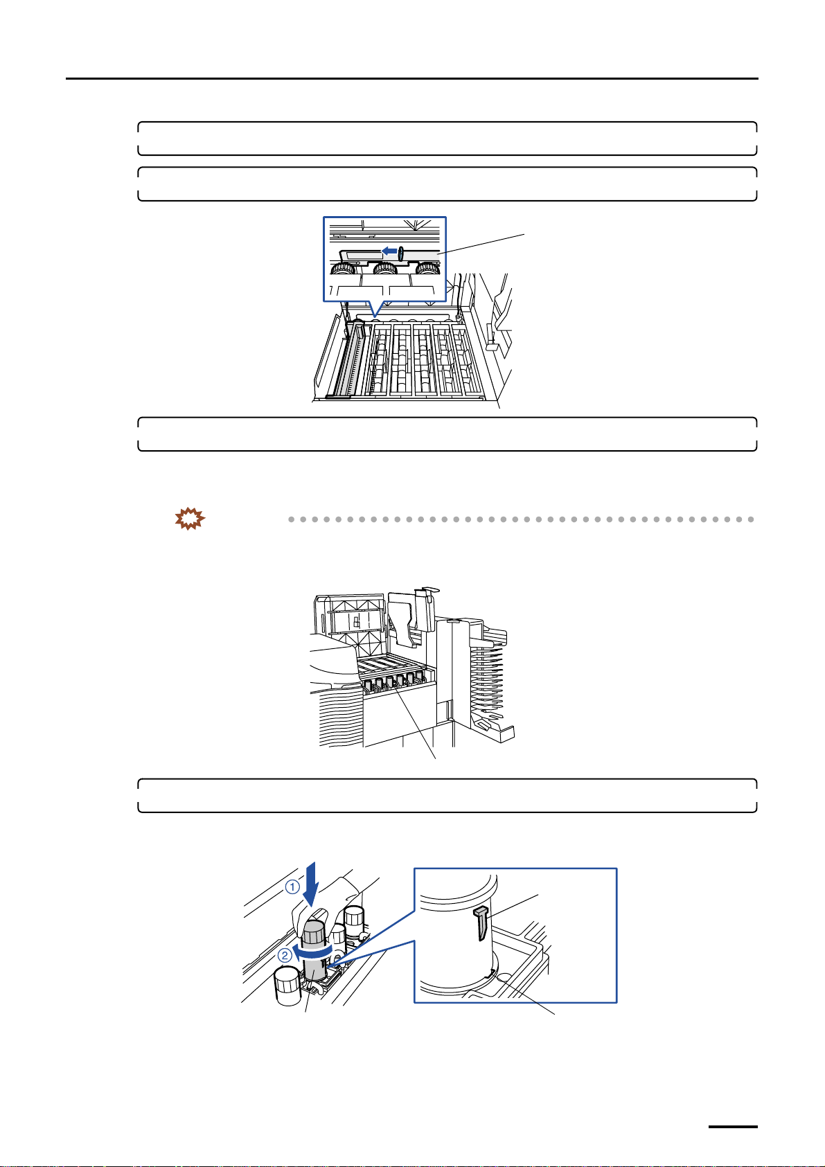
7 Filling the tanks with processing and replenishment solutions
Distributed by: minilablaser.com
3. Attach the processing rack (No. 1).
4. Move the rack stoppers to lock the processing racks.
Rack stopper
5. Pour the processing solution into the sub-tank.
Pour each processing solution into the sub-tank in the reverse order of the developing process.
The level of the processing solution will fall down after the circuit breaker was turned on and the solution was
circulated. So, leave the solution to add.
IMPORTANT
• Do not splash the processing solution over the place other than the sub-tank in which the solution is
being poured.
• Pour in the processing solution slowly to prevent it from producing bubbles.
G068927
6. Attach the filter pipes securely.
Align the projection of the filter pipe with the sub-tank cutout and insert slowly. Insert the bottom end of the filter
pipe into the hole on the bottom of the sub-tank. Then turn the filter pipe clockwise until it stops to secure it.
Filter pipe
Sub-tank
G068947
Projection
Cutout
G068867
75
Page 90
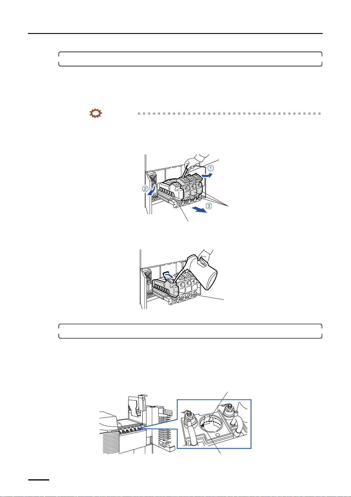
7 Filling the tanks with processing and replenishment solutions
Distributed by: minilablaser.com
7. Pour the replenishment solutions.
(1) Open the processor doors and pull the replenishment unit towards you.
(2) Fill each replenishment solution tank with replenishment solutions.
Pour water and chemical solution into a replenishment solution tank following the instructions in the
Processing Manual or that supplied with the chemical solution, and mix them.
IMPORTANT
• Use water at the temperature specified by the manufacturers of the chemical solution.
• Each replenishment solution tank has a capacity of 11 liters. Do not fill up the replenishment
solution tank, or the solution will overflow during agitation.
• Agitate the replenishment solution slowly to avoid splashing.
Agitation bar
Replenishment solution tanks
Replenishment unit
(3) Pour water into the refilling water tank.
Open the water inlet cover and fill the tank with water.
Refilling water tank
(4) After filling each replenishment solution tank, return the replenishment unit.
8. Confirm the amount of processing solution.
(1) Turn on the main power supply and circuit breaker. Circulate the processing solution.
It circulates the processing solution.
(2) Check the processing solution level in each processing tank.
If the processing solution in a tank is found to be below the cutout of the sub-tank, add some extra processing
solution that has been stored in a separate container in the sub-tank.
Level check position
G068917
G073036
76
Cutout
G068979
Page 91
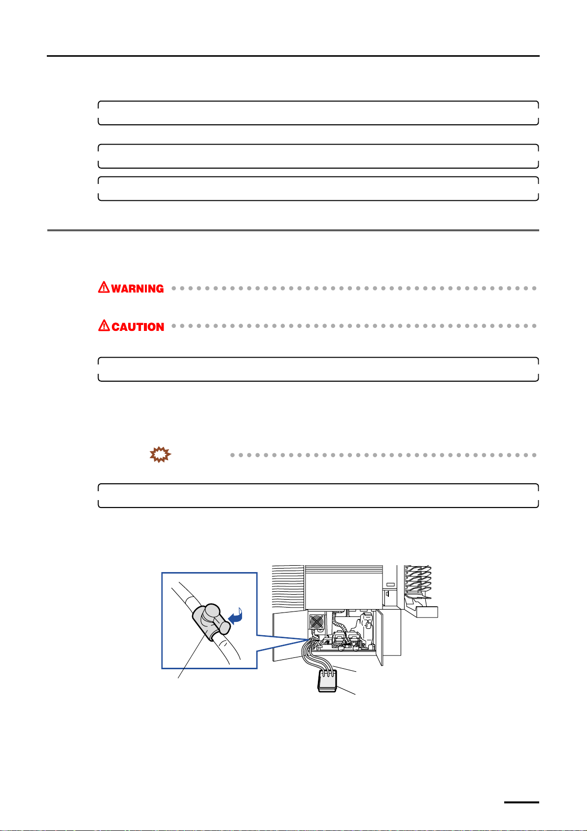
7 Filling the tanks with processing and replenishment solutions
Distributed by: minilablaser.com
(3) Reattach the upper guides.
9. Check the levels of printer and paper processor again.
If necessary, adjust the level.
10. Reattach the cover.
11. Close processor doors 1 and 2.
This completes filling the tanks with processing and replenishment solutions [N].
7.2 Filling the tanks with processing solutions and attaching the replenishment packages [SM]
• Processing solution can cause eye irritation. Wear safety goggles.
• Processing solution can cause skin irritation. Wear rubber gloves and clothing for work wear.
1. Prepare to pour the processing solution.
(1) Pour water and chemical solution into the other container following the instructions in the Processing
Manual or that supplied with the chemical solution, and mix them. (For your convenience, use the
mixing tank.)
For tank capacity, refer to the Processor information in the Specifications.
IMPORTANT
• Use water at the temperature specified by the manufacturers of the chemical solution.
2. Wash the processing tanks.
Wash all the tanks according to the procedure below.
(1) Connect the hose to the drain valve of each processing solution tank, and put the other end of the hose
in a drain or a container.
(2) Open the drain valve of each processing solution tank, wash the inside of the tanks, and then close the
drain valves.
(3) Fill the processing solution tanks with water up to the overflow port, and then ensure that there is no
water leakage.
(4) If there is no water leakage, open the drain valve to discharge the water from the tank.
Drain valve
Hose
Container
G071468
77
Page 92
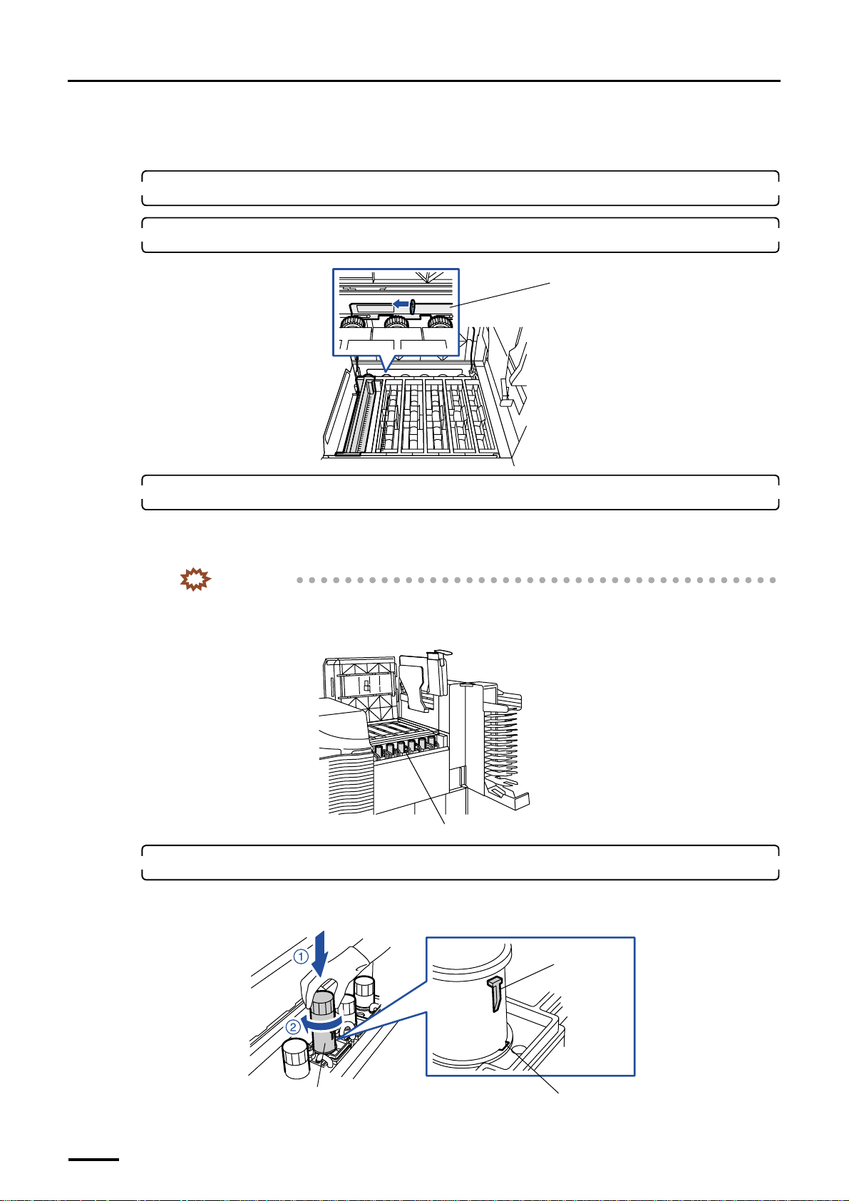
7 Filling the tanks with processing and replenishment solutions
Distributed by: minilablaser.com
(5) Make sure that the processing solution tanks are completely empty, and then close the drain valves.
(6) Wash each tank in the same procedure.
3. Attach the processing rack (No. 1).
4. Move the rack stoppers to lock the processing racks.
Rack stopper
G068927
5. Pour the processing solution into the sub-tank.
Pour each processing solution into the sub-tank in the reverse order of the developing process.
The level of the processing solution will fall down after the circuit breaker was turned on and the solution was
circulated. So, leave the solution to add.
IMPORTANT
• Do not splash the processing solution over the place other than the sub-tank in which the solution is
being poured.
• Pour in the processing solution slowly to prevent it from producing bubbles.
Sub-tank
6. Attach the filter pipes securely.
Align the projection of the filter pipe with the sub-tank cutout and insert slowly. Insert the bottom end of the filter
pipe into the hole on the bottom of the sub-tank. Then turn the filter pipe clockwise until it stops to secure it.
G068947
78
Filter pipe
Projection
Cutout
G068867
Page 93
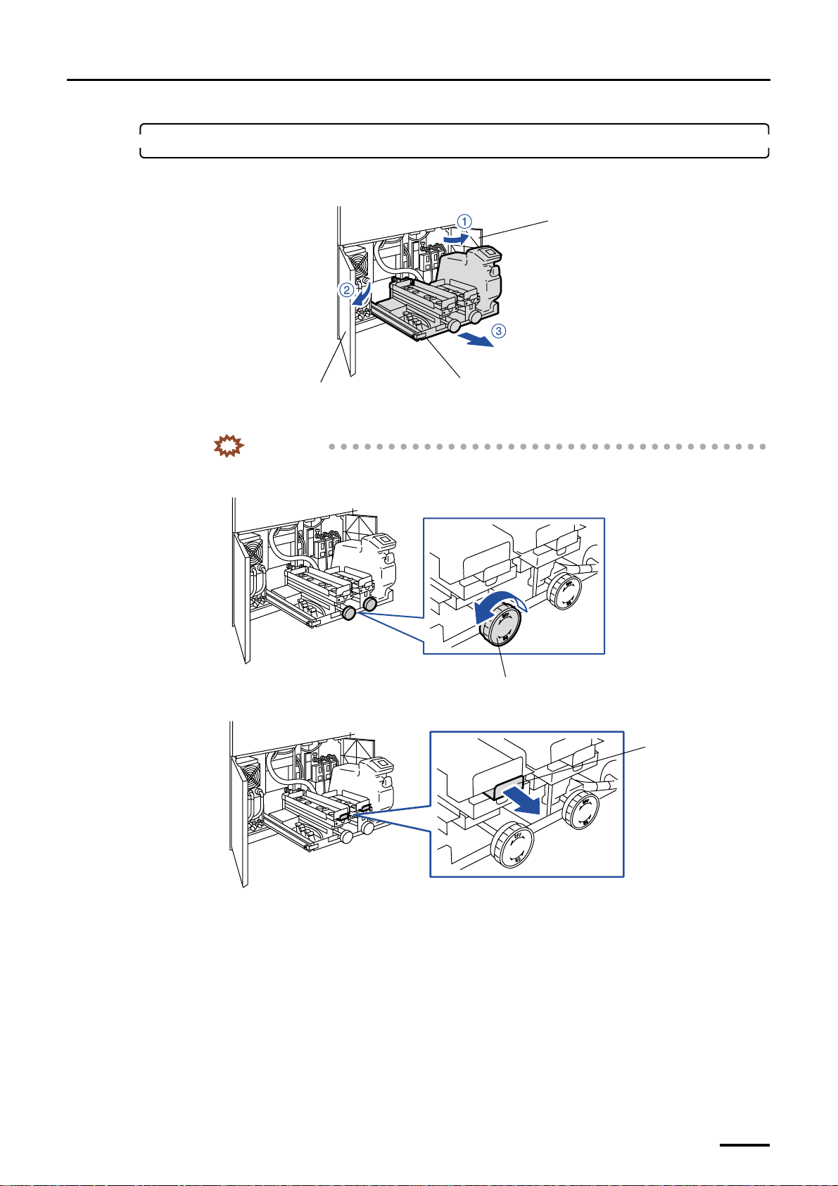
7 Filling the tanks with processing and replenishment solutions
Distributed by: minilablaser.com
7. Attach the replenishment package.
(1) Open processor doors 1 and 2, then draw the replenishment package unit frontward.
Processor door 2
Replenishment package unit
Processor door 1
(2) Turn the handle counterclockwise.
IMPORTANT
• Be sure to turn the handle fully counterclockwise so that the indication of OFF on the label
attached on the handle comes to the top.
G071413
(3) Pull the valve chuck toward you.
(4) Remove all the caps from the replenishment packages.
Handle
G071392
Valve chuck
G071394
79
Page 94
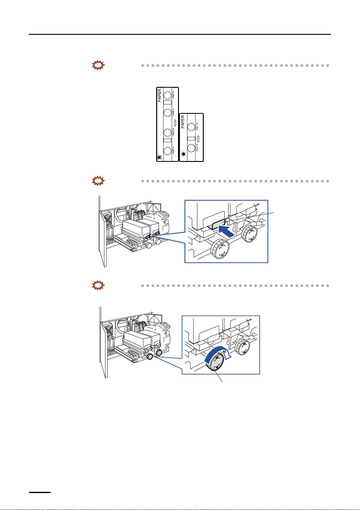
7 Filling the tanks with processing and replenishment solutions
Distributed by: minilablaser.com
(5) Face the inlet port of replenishment package down and place it on the tray of replenishment unit.
IMPORTANT
• Attaching direction of the replenishment package is decided. Attach the replenishment
package as shown in the figure on the tray.
(6) Push the valve chuck to its original position, and secure the replenishment package.
IMPORTANT
• Raise the replenishment package slightly and check that they are firmly secured.
G051343
Valve chuck
(7) Turn the handle clockwise.
IMPORTANT
• Be sure to turn the handle fully clockwise so that the indication of ON on the label attached on
the handle comes to the top.
Handle
G071395
G071393
80
Page 95
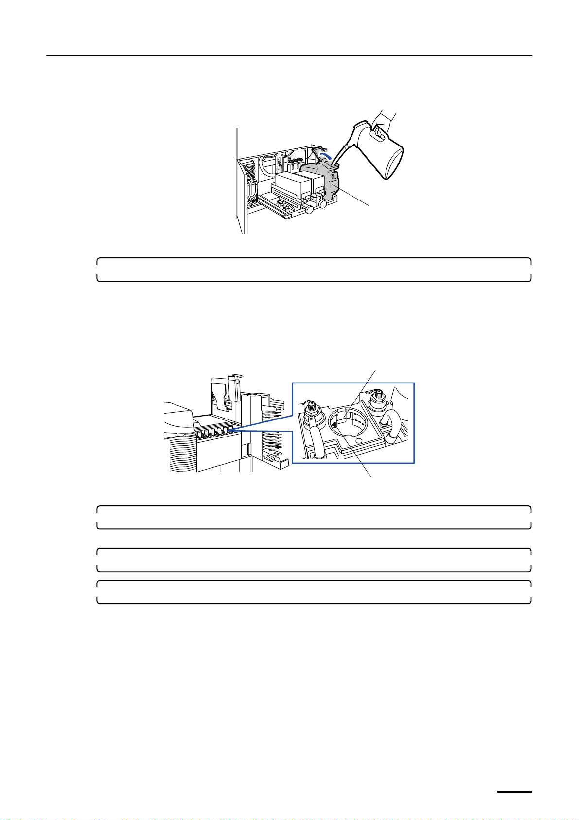
7 Filling the tanks with processing and replenishment solutions
Distributed by: minilablaser.com
(8) Pour water into the water supply tank.
Open the water inlet cover and fill the tank with water.
Water supply tank
(9) After pouring water, close the water inlet cover and return the replenishment package unit.
8. Confirm the amount of processing solution.
(1) Turn on the main power supply and circuit breaker.
It circulates the processing solution.
G071427
(2) Check the processing solution level in each processing tank.
If the processing solution in a tank is found to be below the cutout of the sub-tank, add some extra processing
solution that has been stored in a separate container in the sub-tank.
(3) Reattach the upper guides.
9. Check the levels of printer and paper processor again.
If necessary, adjust the level.
10. Reattach the covers.
11. Close processor doors 1 and 2.
Level check position
Cutout
G068979
This completes filling the processing solutions and attaching the replenishment packages [SM].
81
Page 96
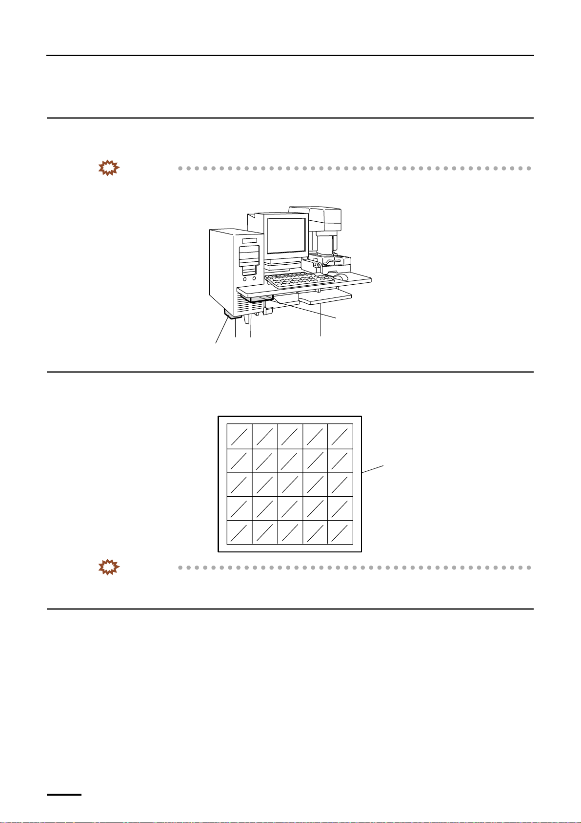
8 Miscellaneous work
Distributed by: minilablaser.com
8 Miscellaneous work
8.1 Storing the enclosed floppy disks and CD-ROMs
Store the floppy disks and CD-ROMs in the pocket under the table.
IMPORTANT
• Store the recovery CD only in the pocket under the PC.
Example: For the machine with the scanner
Pocket
Pocket for recovery CD
G078910
8.2 Attaching the float switch check date entry sticker
Attach the check date entry sticker for the float switch on the machine (the place according to the user's request).
Check date entry sticker
G061342
IMPORTANT
• Instruct the customer to check the float switch within three month from the installation when you install the
machine.
8.3 Writing down the date of installation on the battery replacement label
Write down the installation date on the battery replacement label.
The machine is equipped with an uninterruptible power supply (UPS) and the battery is in the UPS.
And the computer of the machine is equipped with a lithium battery.
82
Page 97
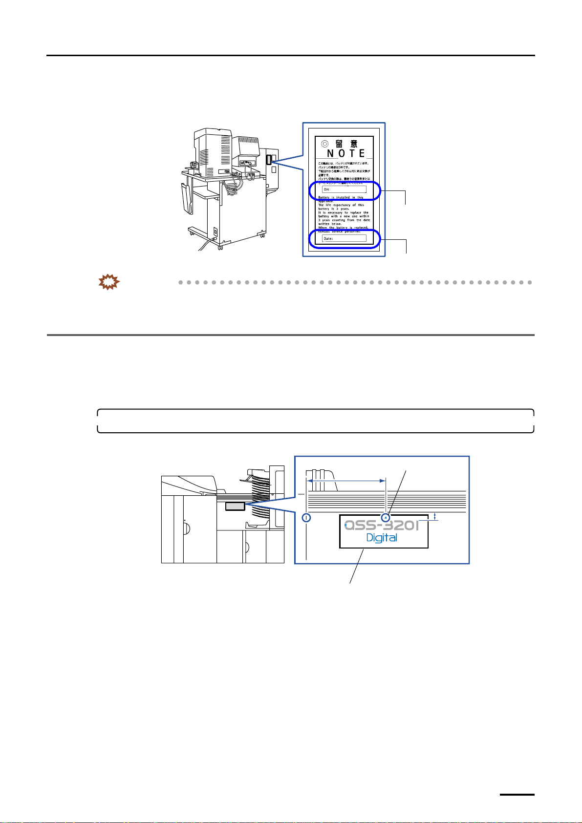
8 Miscellaneous work
Distributed by: minilablaser.com
The estimated life of the batteries is about three years. It is necessary to replace the battery with a new one within three years
after the date of the installation.
Example: For the machine with the scanner
For Japanese
IMPORTANT
• When installing the machine, explain to the customers that the battery should be replaced with a new one
within three years after the date of installation, and ask them to contact their places of purchase when the
replacement is required.
8.4 Attaching the labels
8.4.1 System label
Attach the system label to the paper processor section.
1. Attach the system label to the paper processor section.
Attaching position of the system label [N] [SM]
200 mm
For English
Mark
G068981
20 mm
System label
Attach the system label only for the machine.
G068982
83
Page 98
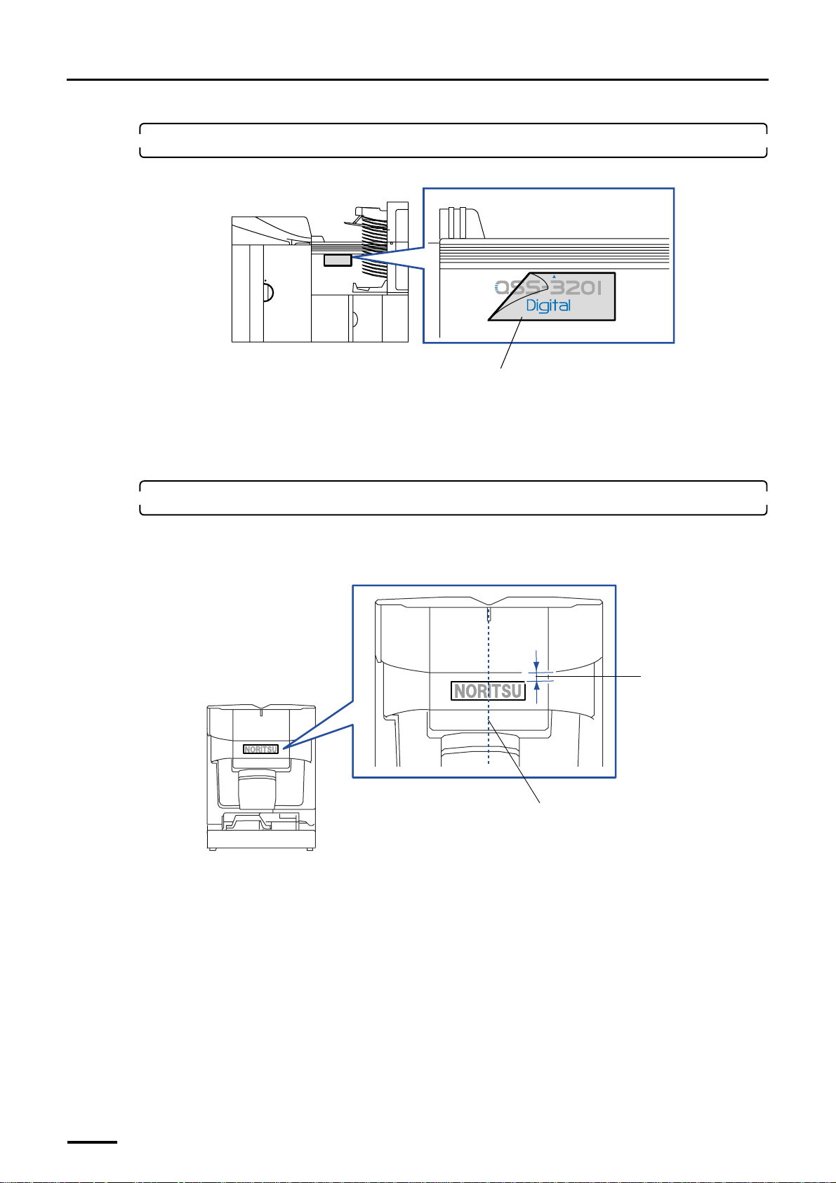
8 Miscellaneous work
Distributed by: minilablaser.com
2. Peel the cellophane off the system label.
Do not peel off the characters on the label together.
8.4.2 Labels for NORITSU only
Attach Noritsu label (small) to the scanner and desk, Noritsu label (large) to the printer and Noritsu logo label to the
processor.
1. Attach the Noritsu label (small).
(1) Peel off the mount and attach the label to the scanner section.
This operation is necessary when the scanner has been equipped.
Cellophane
G072105
20 mm
84
Align it to the center and attach the label to the
machine.
G081090
Page 99
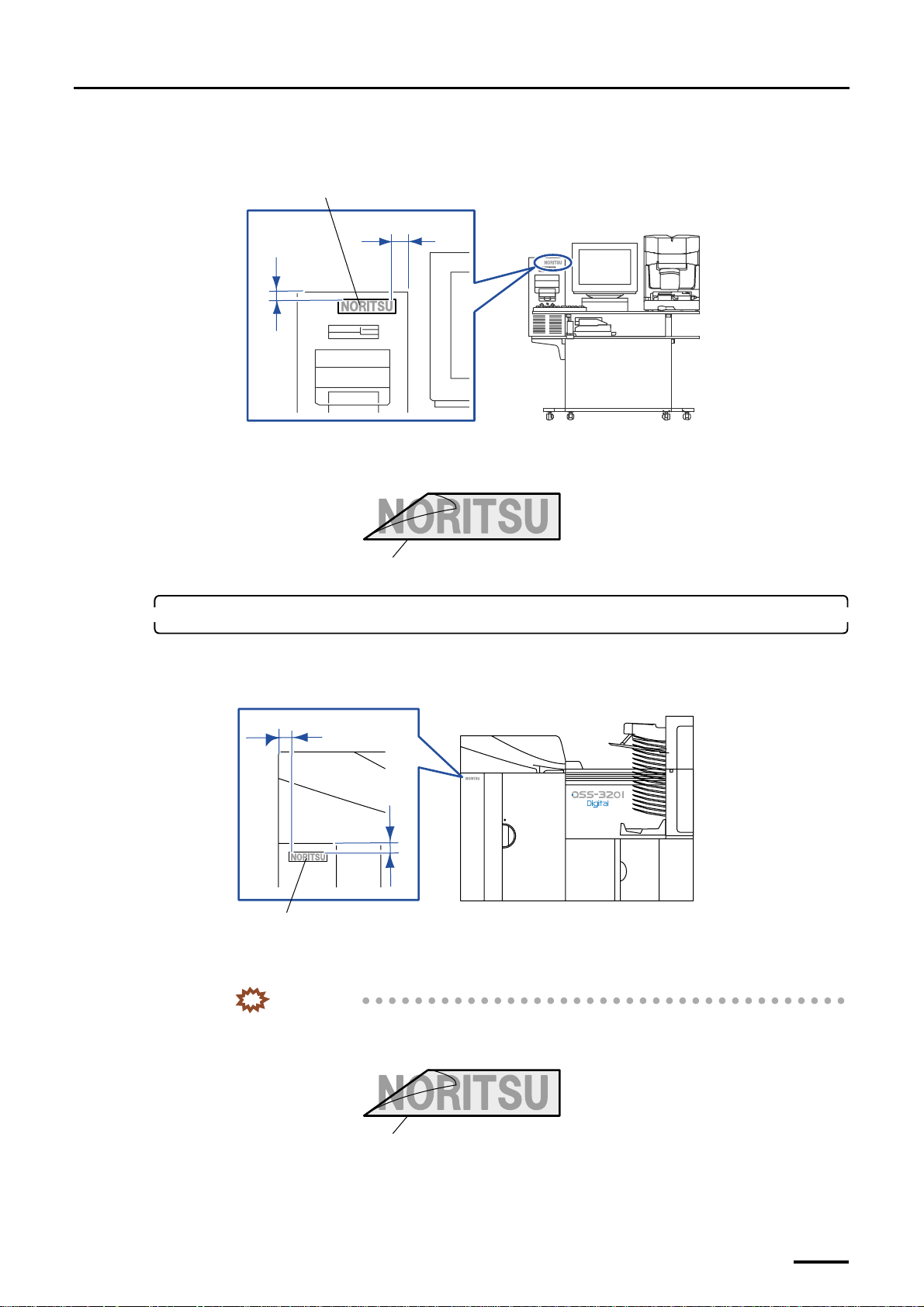
(2) Peel off the mount and attach the label to the desk section.
Distributed by: minilablaser.com
Position of the Noritsu label (small)
Noritsu label (small)
20 mm
7 mm
(3) Peel off the cellophane.
Do not peel off the characters on the label together.
8 Miscellaneous work
G077907
Cellophane
2. Attach the Noritsu label (large).
(1) Peel off the mount and attach the label to the printer section.
Position of the Noritus label (large)
35 mm
25.5 mm
Noritsu label (large)
(2) Peel off the cellophane.
Do not peel off the characters on the label together.
IMPORTANT
• Let enough time pass then remove the cellophane from the Noritus label (large).
The seal is easy to remove immediately after the attachment.
G081359
G077909
Cellophane
G081359
85
Page 100
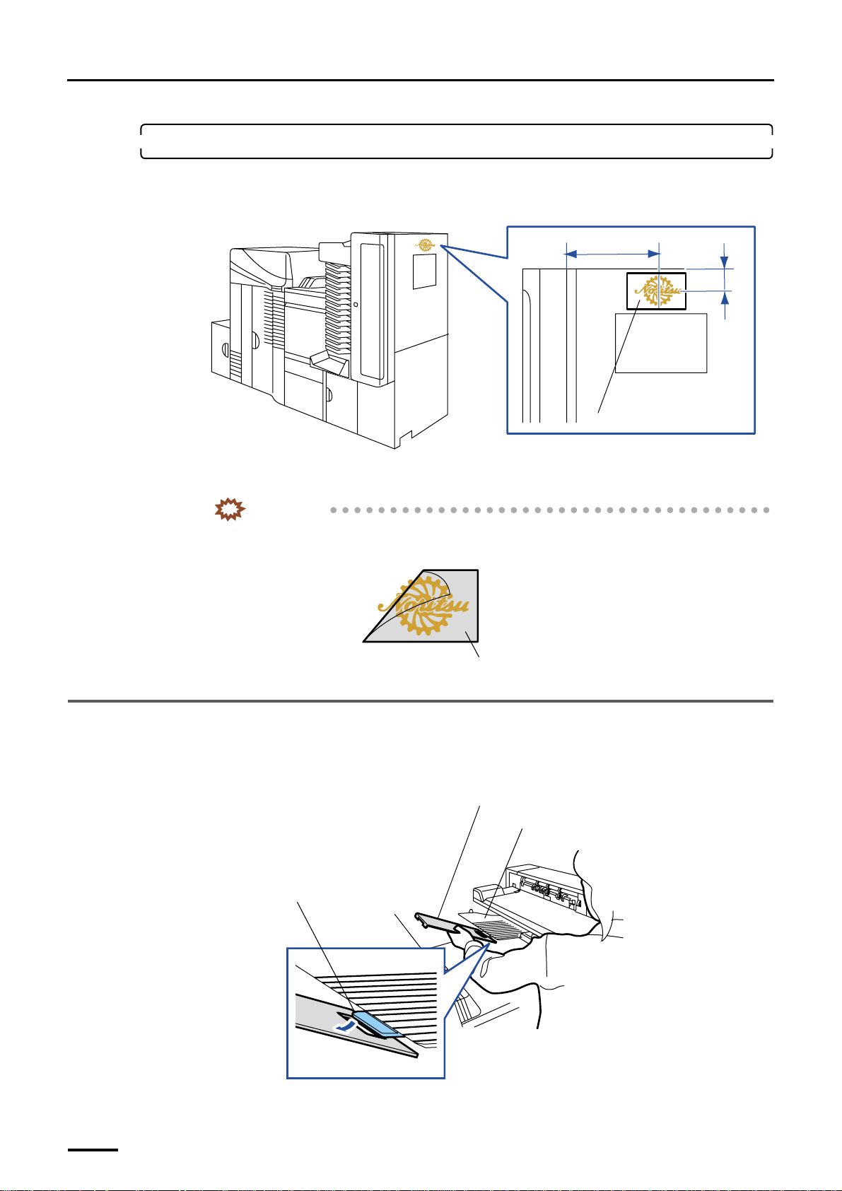
8 Miscellaneous work
Distributed by: minilablaser.com
3. Attach the NORITSU logo label.
(1) Peel off the mount and attach the label to the processor section.
(2) Peel off the cellophane.
Position of the NORITSU logo label
375 mm
65 mm
NORITSU logo label
G077911
Do not peel off the NORITSU logo label together.
IMPORTANT
• Let enough time pass then remove the cellophane from the NORITSU logo label.
The seal is easy to remove immediately after the attachment.
Cellophane
8.5 Attaching the Long Length Print Tray
This is not necessary for the machine with the optional print accumulation tray.
1. Hook the hole on Long Length Print Tray onto the print receiving tray (large).
Hole for hooking
G081314
Long Length Print Tray
Print receiving tray (large)
86
G068138
 Loading...