

Page 1
VS2672926-KG00E
REVISION E
MAY 2007
VS18/VS26 VALVE ADVANTAGE
MAINTENANCE & INSTRUCTION BOOKLET
Page 2

VS18/VS26 MAINTENANCE & INSTRUCTION BOOKLET
1 CONTENT
1 CONTENT ..............................................................................................................................................2
2 VS18/VS26-SYSTEM OVERVIEW ...........................................................................................................5
3 SAFETY, WARNING ................................................................................................................................6
4 TECHNICAL DATA...................................................................................................................................8
4.1 SPECIFICATION ..................................................................................................................................8
4.1.1 Ambient temperature .............................................................................................................................8
4.1.2 Medium temperature.............................................................................................................................. 8
4.1.3 Medium.................................................................................................................................................. 8
4.1.4 Air quality............................................................................................................................................... 8
4.2 MATERIALS........................................................................................................................................9
4.3 PNEUMATIC .....................................................................................................................................10
4.3.1 Response times VS valves .................................................................................................................. 10
4.3.2 Flow..................................................................................................................................................... 11
4.3.3 Maximum cycling rate .......................................................................................................................... 11
4.3.4 Minimum impulse on bistable valves ................................................................................................... 11
4.3.5 Important information for 2x2/2 valves................................................................................................. 11
4.4 ELECTRICAL ....................................................................................................................................12
4.4.1 Voltage tolerances ............................................................................................................................... 12
4.4.2 Required performance of power supply unit ........................................................................................ 12
4.4.3 Power supply and precautions............................................................................................................. 12
4.5 COMPLIANCE AND APPROVALS ..........................................................................................................13
4.5.1 CE marking.......................................................................................................................................... 13
4.5.2 ATEX (Directive 94/9/EC) for 24V DC only.......................................................................................... 13
4.5.3 ISO standard ....................................................................................................................................... 14
4.5.4 Fieldbus standards .............................................................................................................................. 14
4.5.5 CNOMO standard................................................................................................................................ 14
4.5.6 DIN standard ....................................................................................................................................... 14
4.5.7 UL/CSA approval................................................................................................................................. 14
5 INSTALLATION AND MAINTENANCE MECHANICAL.....................................................................................15
5.1 INSTALLATION ..................................................................................................................................15
5.1.1 Tools.................................................................................................................................................... 15
5.1.2 Tightening torque................................................................................................................................. 15
5.1.3 Port identification ................................................................................................................................. 16
5.1.4 Assembly of VS18/VS26 valve islands ................................................................................................ 17
5.1.5 Valve identification labels .................................................................................................................... 21
5.1.6 Internal/external pilot air supply ...........................................................................................................22
5.1.7 Multi pressure ...................................................................................................................................... 23
5.1.8 DIN-rail assembly ................................................................................................................................24
5.1.9 Installation instruction in case of raised vibrations ............................................................................... 25
5.1.10 Sandwich plates................................................................................................................................... 26
5.1.11 Replacement of valves ........................................................................................................................ 28
5.1.12 Replacement of pilot valves................................................................................................................. 29
5.1.13 Manual override set-up kit ................................................................................................................... 30
5.1.14 Blanking plug for base connector hole................................................................................................. 31
5.2 MAINTENANCE .................................................................................................................................32
5.2.1 Lubrication ........................................................................................................................................... 32
5.2.2 Spare parts .......................................................................................................................................... 33
6 SINGLE STATION SUB-BASE..................................................................................................................34
6.1 GENERAL INFORMATION ...................................................................................................................34
6.1.1 24V DC power supply .......................................................................................................................... 34
6.1.2 115V AC power supply ........................................................................................................................ 34
6.1.3 Max current load on valve connectors with 24V DC ............................................................................ 34
6.1.4 Max current load on valve connectors with 115V AC........................................................................... 34
6.2 VARIANT WITH M12 CONNECTOR......................................................................................................35
6.2.1 Pin assignment (acc. VDMA 24571) .................................................................................................... 35
6.3 VARIANT WITH NPTF1/2“ CONDUIT WITH FLYING LEADS .....................................................................36
6.3.1 Wiring information................................................................................................................................ 36
VS2672926-KG00E_05/07 Page 2/97
Page 3

VS18/VS26 MAINTENANCE & INSTRUCTION BOOKLET
7 MULTIPOLE..........................................................................................................................................37
7.1 GENERAL INFORMATION....................................................................................................................37
7.1.1 24V DC power supply...........................................................................................................................37
7.1.2 115V AC power supply.........................................................................................................................37
7.1.3 Max current load on valve connectors with 24V DC .............................................................................37
7.1.4 Max current load on valve connectors with 115V AC ...........................................................................37
7.2 VARIANTS WITH D-SUB CONNECTORS ...............................................................................................38
7.2.1 D-Sub assembly / Installation of PCB...................................................................................................38
7.2.2 Pin assignment.....................................................................................................................................39
7.3 VARIANT WITH NPTF1” CONDUIT ENTRY WITH TERMINALS ..................................................................42
7.3.1 NPTF1” conduit entry with terminals assembly / Installation of PCB ....................................................42
7.3.2 Pin assignment.....................................................................................................................................44
7.4 VARIANT WITH M23 CONNECTOR ......................................................................................................45
7.4.1 M23 assembly / Installation of PCB......................................................................................................45
7.4.2 Pin assignment.....................................................................................................................................46
8 FIELDBUS............................................................................................................................................47
8.1 GENERAL INFORMATION....................................................................................................................47
8.1.1 Power supply and pin assignment........................................................................................................48
8.1.2 Max. current load on valve connectors.................................................................................................48
8.1.3 Fieldbus assembly / Installation of PCBs (excluding AS-Interface and FD67 bus)...............................49
8.1.4 AS-Interface assembly / Installation of PCBs .......................................................................................50
8.1.5 FD67 bus assembly / Installation of PCB .............................................................................................51
8.2 PROFIBUS DP..................................................................................................................................52
8.2.1 Profibus DP pin assignment .................................................................................................................52
8.2.2 Profibus DP wiring................................................................................................................................53
8.2.3 Profibus DP address and baud rate setting..........................................................................................55
8.2.4 Profibus DP output addressing.............................................................................................................56
8.2.5 Diagnostics...........................................................................................................................................57
8.2.6 Profibus DP LED indicators..................................................................................................................57
8.2.7 Profibus DP commissioning..................................................................................................................57
8.2.8 GSD file................................................................................................................................................58
8.2.9 Profibus DP valve island expansion .....................................................................................................58
8.2.10 More information on Profibus DP .........................................................................................................58
8.3 DEVICENET .....................................................................................................................................59
8.3.1 DeviceNet pin assignment....................................................................................................................59
8.3.2 DeviceNet wiring ..................................................................................................................................59
8.3.3 DeviceNet address and baud rate setting.............................................................................................61
8.3.4 DeviceNet output addressing ...............................................................................................................61
8.3.5 Diagnostics...........................................................................................................................................62
8.3.6 DeviceNet LED indicators ....................................................................................................................62
8.3.7 DeviceNet EDS files and commissioning..............................................................................................63
8.3.8 DeviceNet valve island expansion........................................................................................................64
8.3.9 More information on DeviceNet ............................................................................................................64
8.4 CANOPEN .......................................................................................................................................65
8.4.1 CANopen pin assignment.....................................................................................................................65
8.4.2 CANopen wiring ...................................................................................................................................66
8.4.3 CANopen address and baud rate setting..............................................................................................67
8.4.4 CANopen output addressing ................................................................................................................68
8.4.5 Diagnostics...........................................................................................................................................68
8.4.6 CANopen LED indicators .....................................................................................................................69
8.4.7 CANopen commissioning .....................................................................................................................70
8.4.8 CANopen valve island expansion.........................................................................................................70
8.4.9 More information on CANopen .............................................................................................................70
8.5 INTERBUS-S ....................................................................................................................................71
8.5.1 Interbus-S pin assignment....................................................................................................................71
8.5.2 Interbus-S wiring ..................................................................................................................................72
8.5.3 Interbus-S address and baud rate setting ............................................................................................72
8.5.4 Interbus-S output addressing ...............................................................................................................72
8.5.5 Diagnostics...........................................................................................................................................72
8.5.6 Interbus-S LED indicators ....................................................................................................................73
8.5.7 Interbus-S ID and length codes............................................................................................................74
8.5.8 Interbus-S commissioning ....................................................................................................................75
8.5.9 Interbus-S valve island expansion........................................................................................................75
8.5.10 More information on Interbus-S............................................................................................................75
VS2672926-KG00E_05/07 Page 3/97
Page 4

VS18/VS26 MAINTENANCE & INSTRUCTION BOOKLET
8.6 AS-INTERFACE ................................................................................................................................76
8.6.1 AS-Interface pin assignment................................................................................................................ 76
8.6.2 AS-Interface wiring .............................................................................................................................. 77
8.6.3 AS-Interface address and baud rate setting ........................................................................................ 77
8.6.4 AS-Interface single slave valve island configurations and settings ......................................................78
8.6.5 AS-Interface single slave output addressing........................................................................................ 78
8.6.6 AS-Interface double slave valve island configurations and settings..................................................... 79
8.6.7 AS-Interface double slave output addressing ......................................................................................80
8.6.8 Diagnostics .......................................................................................................................................... 81
8.6.9 AS-Interface LED indicators ................................................................................................................ 81
8.6.10 AS-Interface ID and I/O configuration codes ....................................................................................... 82
8.6.11 AS-Interface commissioning ................................................................................................................ 82
8.6.12 AS-Interface valve island expansion.................................................................................................... 82
8.6.13 More information on AS-Interface........................................................................................................ 82
8.7 FD67 BUS .......................................................................................................................................83
8.7.1 FD67 bus pin assignment .................................................................................................................... 83
8.7.2 Wiring termination................................................................................................................................ 84
8.7.3 FD67 bus output addressing................................................................................................................ 84
8.7.4 FD67 bus LED indicators and diagnostics ........................................................................................... 85
8.7.5 FD67 bus commissioning .................................................................................................................... 85
8.7.6 FD67 Profibus GSD file ....................................................................................................................... 85
8.7.7 FD67 DeviceNet EDS file .................................................................................................................... 86
8.7.8 FD67 CANopen EDS file ..................................................................................................................... 86
8.7.9 FD67 valve island expansion ............................................................................................................... 86
8.7.10 More information on FD67 ................................................................................................................... 86
9 VALVE ISLAND EXPANSION....................................................................................................................87
9.1 GENERAL INFORMATION ...................................................................................................................87
9.2 ASSEMBLY OF SINGLE ADD-ON STATIONS FOR MULTIPOLE AND FIELDBUS VALVE ISLANDS ....................88
10 USE IN AREAS WITH POTENTIALLY EXPLOSIVE ATMOSPHERE (94/9/EC „ATEX“) – OPERATING MANUAL AND
DECLARATION OF CONFORMITY
.............................................................................................................90
10.1 INTENDED USAGE.............................................................................................................................90
10.2 OPERATING MANUAL ATEX .............................................................................................................90
10.2.1 General conditions............................................................................................................................... 90
10.2.2 Installation ........................................................................................................................................... 91
10.2.3 Operating............................................................................................................................................. 91
10.2.4 Failures................................................................................................................................................ 92
10.2.5 Maintenance and repair ....................................................................................................................... 92
10.3 ATEX CONFORMITY.........................................................................................................................93
10.3.1 Operating conditions............................................................................................................................ 93
10.3.2 Labels .................................................................................................................................................. 93
10.3.3 Specific conditions............................................................................................................................... 94
10.3.4 Declaration of conformity ..................................................................................................................... 94
11 TRANSPORT / STORAGE / PACKAGING...................................................................................................96
12 REVISION INDEX...................................................................................................................................97
VS2672926-KG00E_05/07 Page 4/97
Page 5
VS18/VS26 MAINTENANCE & INSTRUCTION BOOKLET
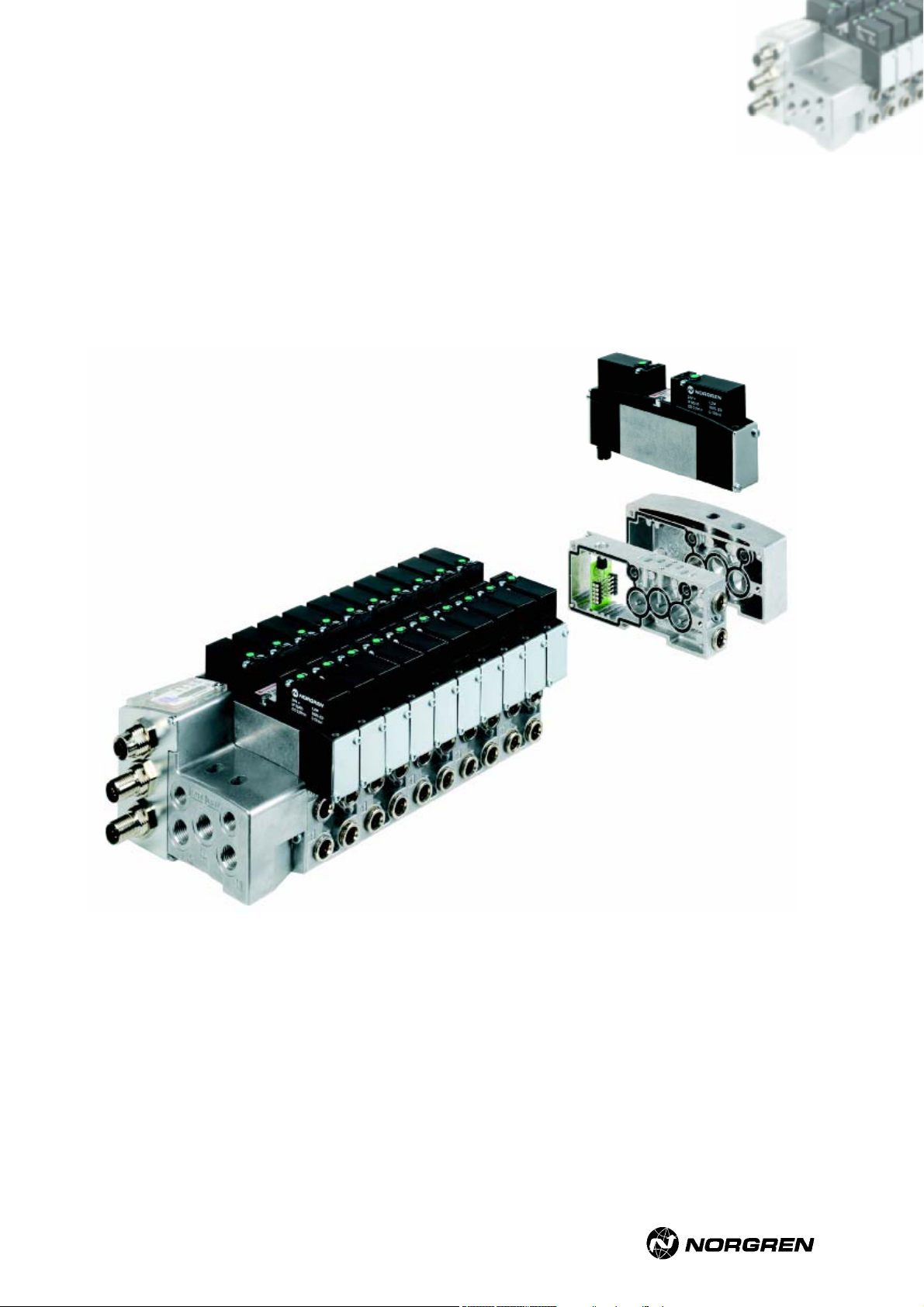
2 VS18/VS26-SYSTEM OVERVIEW
24V DC or 115V AC Multipole
Integrated Fieldbus
Field expandable with single add-on stations
Dual spool technology
VS18G/VS26G Glandless spool and sleeve
for long life
VS18S/VS26S Softseal spool
for high flow
Wide range of accessories
UL and ATEX
Universal PNP/NPN 24V DC Multipole
Please find ordering information of all components in the data sheets 5.4.159 (VS18) and
5.4.160 (VS26).
VS2672926-KG00E_05/07 Page 5/97
Page 6

VS18/VS26 MAINTENANCE & INSTRUCTION BOOKLET
3 SAFETY, WARNING
These products are intended for use in industrial compressed air or hydraulic systems only. Do
not use these products where pressures and temperatures can exceed those listed under
‘
Technical Data’.
Before using these products with fluids other than those specified, for non-industrial
applications, life-support systems, or other applications not within published specifications,
consult NORGREN. Through misuse, age, or malfunction, components used in fluid power
systems can fail in various modes. The system designer is warned to consider the failure modes
of all component parts used in fluid power systems and to provide adequate safeguards to
prevent personal injury or damage to equipment in the event of such failure.
System designers must provide a warning to end users in the system instructional
manual if protection against a failure mode cannot be adequately provided. System
designers and end users are cautioned to review specific warnings found in instruction sheets
packed and shipped with these products.
Specific warnings:
• Check if classification of the valve island and marking on the item of equipment are able for
case of operation.
• Check technical data, such as operating pressure, voltage level, current type and
temperature, on the product label or in the data sheets for compliance with the existing
operating conditions.
• After removing the packaging, make sure that no contamination enter into the system.
• Check before the installation of the system that no contamination exists in the piping and
valve island.
• Check during installation of the system that gaskets will not become damaged.
• Please consider the information of this operating manual as well as the use conditions and
permissible data, which are on the product labels.
• Adapt to the general rules of technology when selecting and using an item of equipment.
• Take measures to avoid unintentional or improper activation.
• Prior to the first electrical operation, ensure no danger would result from the medium
exhausting from any open ports.
• Consider in case of pressurised systems that lines, valves and other components should not
be removed.
•
ATTENTION: There is some risk of injury! The surface of pilot valves could become very
warm in continuous operation.
•
ATTENTION: Valves with NO function (normally open) are open without pilot pressure.
During commissioning, protection against exhausted medium has to be provided.
• Leak and strength tests on open and closed valves are admissible until max. 1.5 times the
max. operating pressure. It is not allowed to operate the valve during these tests.
• Never use the valve island as lever arm or a step for climbing.
• Protect the valve island from falling objects.
VS2672926-KG00E_05/07 Page 6/97
Page 7

VS18/VS26 MAINTENANCE & INSTRUCTION BOOKLET
• Any fitting position of the valve island is permissible but valves with indicating lights up is
preferred.
• To avoid damaging the product, please make sure that the maximum torque values are not
exceeded (see section
5.1.2).
• Avoid short-circuits and breaks by not deviating from the standard use of connector cables
and cords.
• Order spare parts with the part number indicated on the product labels. (See section
5.2.2
and/or data sheets 5.4.159 (VS18) resp. 5.4.160 (VS26)).
• Do not load the system by bending or torsion.
•
Important: Power must be removed from the system while assembling and disassembling
electrical connectors, plugs and cables, valves, sandwich plates and blanking plates.
• Install and use only complete configured and connected valve islands.
• VS18/VS26 Fieldbus valve islands contain electronic devices, which could be damaged
through electrostatic discharge. Therefore electrostatic precautions must be taken.
Specifically, the person assembling or configuring the valve island must be connected to an
earth ground.
• Please refer to section
4.4.3 for information on power supply and earth ground connection of
Multipole and Fieldbus valve islands.
• Use this booklet or the instruction sheets packed with the product for assembling and
installation.
VS2672926-KG00E_05/07 Page 7/97
Page 8

VS18/VS26 MAINTENANCE & INSTRUCTION BOOKLET
4 TECHNICAL DATA
For more information, please refer to data sheets 5.4.159 (VS18) and 5.4.160 (VS26).
4.1 SPECIFICATION
4.1.1 Ambient temperature
-15°C to +50°C
(Consult our technical service for use below +2°C.)
4.1.2 Medium temperature
-5°C to +50°C
4.1.3 Medium
The valves of these series are intended for use with compressed air only.
The valves must be operated within the pressure range specified in the data sheets 5.4.159
(VS18) and 5.4.160 (VS26).
4.1.4 Air quality
The valves are designed for filtered (40µm), lubricated or non-lubricated compressed air.
(Please find details on oils in section
be supplied for the life of the product.
5.2.1.) If the air supply is lubricated, then lubrication must
VS2672926-KG00E_05/07 Page 8/97
Page 9

VS18/VS26 MAINTENANCE & INSTRUCTION BOOKLET
4.2 MATERIALS
Valve body / sub-bases: Die-cast aluminium
Glandless spool&sleeve (VS**G): Aluminium, hard anodised, teflon coated
Softseal spool (VS**S): Aluminium with HNBR seals
Plastic parts: POM, PA, PPA
Mounting sheets / screws: steel, zinc coated
Springs: stainless steel
Seals: NBR
Sandwich plates: Aluminium bar material, PA
Electrical contacts: brass, tin/gold coated
PCB: Glasepoxy
VS2672926-KG00E_05/07 Page 9/97
Page 10
VS18/VS26 MAINTENANCE & INSTRUCTION BOOKLET
4.3 PNEUMATIC
4.3.1 Response times VS valves
The response measurements are taken according to ISO 12238 standard.
Glandless valves VS**G VS18 VS26
Response
time ON (ms)
5/2 Sol/Spring 18 54 24 58
5/2 Sol/Sol 18 18 20 20
5/2 Sol (priority side 14)/Sol 14
1)
5/3 APB Sol/Sol 24 37 26 52
5/3 COE Sol/Sol 25 49 28 52
Softseal valves VS**S VS18 VS26
Response
time ON (ms)
2x2/2 NC Sol/Sol 24 21 29 29
2x2/2 NO Sol/Sol 24 21 29 29
2x2/2 NO/NC Sol/Sol 24 21 29 29
2x3/2 NC Sol/Sol 20 22 32 25
2x3/2 NO Sol/Sol 20 22 32 25
2x3/2 NO/NC Sol/Sol 20 22 32 25
5/2 Sol/Spring 16 42 18 46
5/2 Sol/Sol 14 14 14 14
5/3 APB Sol/Sol 18 40 20 55
5/3 COE Sol/Sol 18 40 19 55
1)
ON side 14
2)
ON side 12
APB = All ports blocked
COE = Centre open exhaust
NC = Normally closed
NO = Normally open
Response
time OFF (ms)
2)
21
Response
time OFF (ms)
Response
time ON (ms)
1)
14
Response
time ON (ms)
Response
time OFF (ms)
2)
21
Response
time OFF (ms)
VS2672926-KG00E_05/07 Page 10/97
Page 11
VS18/VS26 MAINTENANCE & INSTRUCTION BOOKLET
4.3.2 Flow
The flow values are measured at 6 bar inlet pressure and with a pressure drop of 1 bar.
Glandless valves VS**G VS18 VS26
QN
(L/min)
5/2 Sol/Spring 550 0.48 0.56 1‘000 0.87 1.02
5/2 Sol/Sol 550 0.48 0.56 1‘000 0.87 1.02
5/2 Sol (priority side 14)/Sol 550 0.48 0.56 1‘000 0.87 1.02
5/3 APB Sol/Sol 550 0.48 0.56 1‘000 0.87 1.02
5/3 COE Sol/Sol 550 0.48 0.56 1‘000 0.87 1.02
Softseal valves VS**S VS18 VS26
QN
(L/min)
2x2/2 NC Sol/Sol 550 0.46 0.56 1’150 1.00 1.17
2x2/2 NO Sol/Sol 550 0.46 0.56 1’150 1.00 1.17
2x2/2 NO/NC Sol/Sol 550 0.46 0.56 1’150 1.00 1.17
2x3/2 NC Sol/Sol 600 0.52 0.61 1‘250 1.09 1.27
2x3/2 NO Sol/Sol 600 0.52 0.61 1‘250 1.09 1.27
2x3/2 NO/NC Sol/Sol 600 0.52 0.61 1‘250 1.09 1.27
5/2 Sol/Spring 650 0.57 0.66 1‘350 1.18 1.37
5/2 Sol/Sol 650 0.57 0.66 1‘350 1.18 1.37
5/3 APB Sol/Sol 650 0.57 0.66 1‘350 1.18 1.37
5/3 COE Sol/Sol 650 0.57 0.66 1‘350 1.18 1.37
Kv
(m3/h)
Kv
(m3/h)
Cv (US
Gal/min)
Cv (US
Gal/min)
QN
(L/min)
QN
(L/min)
Kv
(m3/h)
Kv
(m3/h)
Cv (US
Gal/min)
Cv (US
Gal/min)
APB = All ports blocked
COE = Centre open exhaust
NC = Normally closed
NO = Normally open
4.3.3 Maximum cycling rate
In practice the cycling rate should be lower than 300 c.p.m. (<5 Hz). The valves should be
switched above 90% (working port) and below 10% (exhausting port) of the supply pressure.
4.3.4 Minimum impulse on bistable valves
The minimum impulse length on 5/2 way bistable valves should correspond at least twice to the
response time (see section
4.3.1).
4.3.5 Important information for 2x2/2 valves
All 2x2/2 functions (NC, NO or NO/NC) have port 1 not connected in neither end position to port
2 or 4. Port 1 is not necessary (except internal pilot air). Supply of compressed air or vacuum
must be feeded to port 3 or 5.
Pay attention to this when configuring the valve island (blanking off canals 3 and 5 in base) !!
VS2672926-KG00E_05/07 Page 11/97
Page 12

VS18/VS26 MAINTENANCE & INSTRUCTION BOOKLET
4.4 ELECTRICAL
4.4.1 Voltage tolerances
Voltage Voltage tolerances
24V DC +/-10%
115V AC -10%/+15%
4.4.2 Required performance of power supply unit
The required performance can be calculated from the maximum number of energized solenoids
at the same time. In case of a Fieldbus valve island the consumption of power of the electronic
has to be considered (see section
4.4.3 Power supply and precautions
All VS18/VS26 24V DC products are designed to be used with a protective extra low voltage
(PELV) power supply (UL Class 2 Supply only).
All VS18/VS26 115V AC products correspond to the protection class I. Connection of the
protective earth (PE) ground is required.
8).
VS2672926-KG00E_05/07 Page 12/97
Page 13

VS18/VS26 MAINTENANCE & INSTRUCTION BOOKLET
4.5 COMPLIANCE AND APPROVALS
The VS18/VS26 products are tested and compliant:
4.5.1 CE marking
Degrees of protection provided by enclosures (IP code):
EN 60529:91+A1:00 (IEC 60529:89 + A1:99)
Low-voltage switchgear and controlgear:
EN 60947-5-1: 97+A1:00+A2:00+A12:00 - Control circuit devices and switching elements
EN 60947-1: 99+A1:00+A2:01 - Electromechanical control circuit devices
Electromagnetic compatibility (EMC directive 89/336/EEC):
EN 61000-6-2: 01 - Immunity for industrial environments
EN 61000-6-4: 01 - Emission standard for industrial environments
Vibrations- and shock test:
DIN EN 60 068-2-6 - Vibration resistance (Test Fc: Vibration (sinusoidal))
DIN EN 60 068-2-27 (30g) - Shock resistance (Test Ea and guidance: Shock)
4.5.2 ATEX (Directive 94/9/EC) for 24V DC only
EN 50021:99 - Electrical apparatus for potentially explosive atmospheres - Type of
protection "n"
EN 13463-1:02 - Non-electrical equipment for potentially explosive atmospheres. Part 1.
Basic methodology and requirements.
EN 50281-1-1:99 - Electrical apparatus for use in the presence of combustible dust - Part 1-1:
Electrical apparatus protected by enclosures - Construction and testing
EN 1127-1:97 - Explosive atmospheres – Explosion prevention and protection – Part 1 :
Basic concepts and methodology.
For more information please refer to section
10.
VS2672926-KG00E_05/07 Page 13/97
Page 14

VS18/VS26 MAINTENANCE & INSTRUCTION BOOKLET
4.5.3 ISO standard
ISO 15407-2 (size 26mm and 18mm)
4.5.4 Fieldbus standards
Norgren Profibus DP Fieldbus systems conform to
DIN 19245 part 3.
Norgren DeviceNet systems conform to
DeviceNet specification volume 1 release 2 and the Pneumatic Valve Device Profile.
Norgren CANopen Fieldbus systems conform to
CANopen communication profile CiA DS-301 V4.0.
Norgren Interbus-S Fieldbus systems conform to
DIN 19258.
Norgren AS-Interface Fieldbus systems conform to
AS-I V2.11 specification.
For detailed information on Fieldbus protocols please refer to section
8.
4.5.5 CNOMO standard
The M23 19-pin connector fulfils CNOMO standard E03.62.530.N.
For more information on this standard please refer to the CNOMO website
For more information on the M23 19-pin connector please refer to section
www.cnomo.com.
7.4.
4.5.6 DIN standard
Colour code of D-Sub connectors according DIN 47100
4.5.7 UL/CSA approval
Investigated to UL 429 - 5th edition & CSA 22.2 No.139 - 1982 for 24V DC electrically operated
valves.
VS2672926-KG00E_05/07 Page 14/97
Page 15

VS18/VS26 MAINTENANCE & INSTRUCTION BOOKLET
5 INSTALLATION AND MAINTENANCE MECHANICAL
5.1 INSTALLATION
5.1.1 Tools
VS18:
• Hexagon wrench key 2mm
• Hexagon wrench key 2.5mm
• Socket screw key X10
• Philips screwdriver size 1
• Screwdriver size 1
VS26:
• Hexagon wrench key 3mm
• Socket screw key X10
• Philips screwdriver size 1
• Screwdriver size 1
5.1.2 Tightening torque
To avoid damaging the product, please make sure that the maximum torque values are not
exceeded. The maximum torques are specified in the particular installation instructions.
Valve mounting screws
The valve mounting screws are pressurised. To prevent leakage through the mounting screws,
screws with blue coated thread are used. The specified torques for the blue coated screws
reduce to standard values after first use of the screws. These screws should not be used more
than five times, as good sealing performance can then not be guaranteed.
VS2672926-KG00E_05/07 Page 15/97
Page 16
VS18/VS26 MAINTENANCE & INSTRUCTION BOOKLET
5.1.3 Port identification
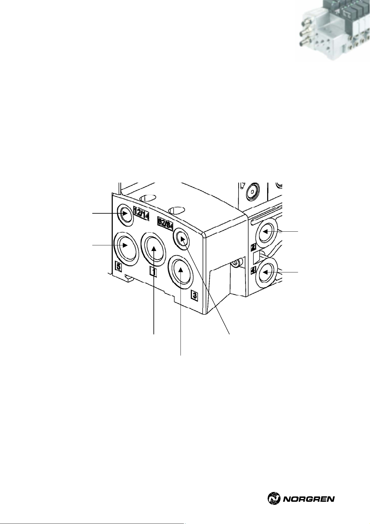
On all end plates and modular sub-bases each port is marked as follows:
Function Port/Identification
Main/internal pilot air supply 1
Exhaust 3 + 5
Outlet 2 + 4
External pilot air supply (if used) 12/14
Collected exhaust of pilot valves 82/84
Note:
Never plug port 82/84. Plugging this port will cause valves to malfunction.
port 12/14
port 5
port 1 port 82/84
port 3
port 2
port 4
VS2672926-KG00E_05/07 Page 16/97
Page 17
VS18/VS26 MAINTENANCE & INSTRUCTION BOOKLET
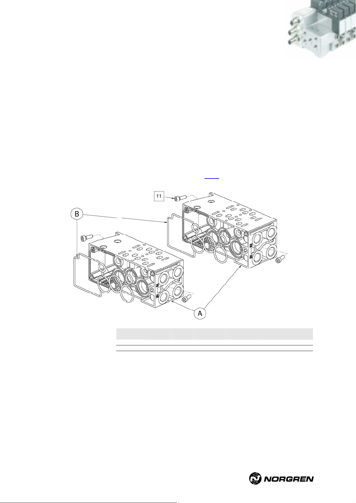
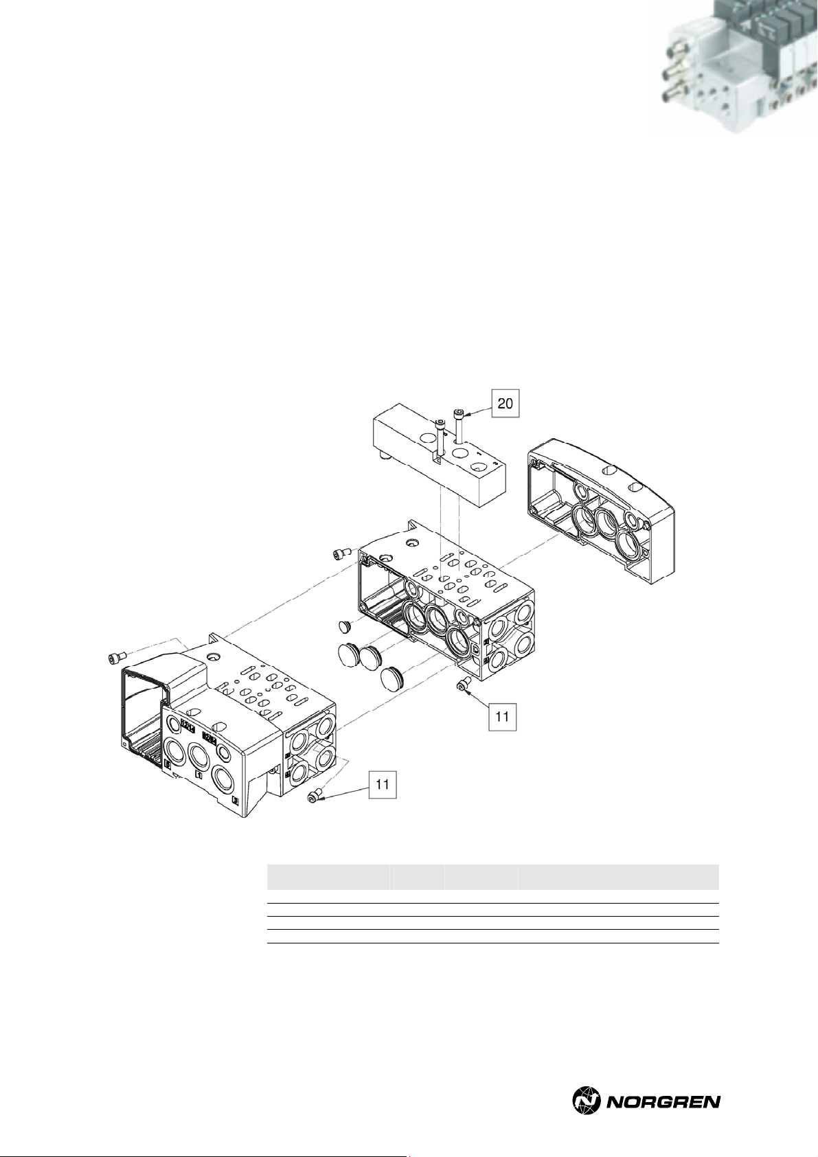
5.1.4 Assembly of VS18/VS26 valve islands
Tools:
VS18: Hexagon wrench key 2.5mm
Philips screwdriver size 1
VS26: Hexagon wrench key 3mm
Philips screwdriver size 1
To assemble a complete valve island, make sure you have ordered all necessary components
and the required tools are available.
1. First bolt all modular sub-bases together. Ensure sub-bases are properly aligned and the
gasket is fitted between the sub-bases. Then tighten the mounting screws (two per modular
sub-base) with the specified torque. If you are using a power screwdriver, consider the
maximum speed allowed.
For multi pressure applications, please refer to section
Screw Type
(thread)
11 M3x10 VS18 0.8 – 0.9 7.08 – 7.96 1100
11 M4x12 VS26 1.0 – 1.1 8.85 – 9.73 1100
Valve
seize
Note:
5.1.7.
Tightening
torque in Nm
Tightening
torque in Ibs
Max. screw driver
speed in r.p.m.
When ordering an even number of stations, please ensure the valve island contains a
maximum of two single station modular sub-bases. E.g.: You order an 8-station Multipole
valve island with an 8-station main PCB. The valve island must have at least three double
station modular sub-bases and must have no more than two single station modular subbases.
When ordering an odd number of stations, the single station modular sub-base should be at
the right end of the valve island. In addition, you can use two additional single station
modular sub-bases, for a total of three.
VS2672926-KG00E_05/07 Page 17/97
Page 18
VS18/VS26 MAINTENANCE & INSTRUCTION BOOKLET
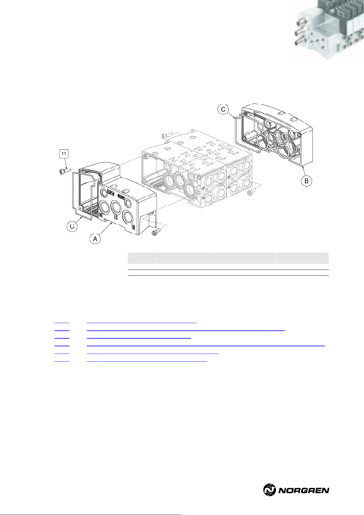
2. Mount the left and right end plate to the modular sub-base. Ensure end plates are properly
aligned and the end plate gasket is fitted. Then tighten the mounting screws (two per end
plate) with the specified torque. If you are using a power screwdriver, consider the maximum
speed allowed.
Screw Type
11 M3x10 VS18 0.8 – 0.9 7.08 – 7.96 1100
11 M4x12 VS26 1.0 – 1.1 8.85 – 9.73 1100
(thread)
Valve
seize
Tightening
torque in Nm
Tightening
torque in Ibs
Max. screw driver
speed in r.p.m.
3. Having assembled the base of the valve island, proceed with the electronic components. For
these instructions please refer to following sections:
7.2.1 D-Sub assembly / Installation of PCB
7.3.1 NPTF1” conduit entry with terminals assembly / Installation of PCB
7.4.1 M23 assembly / Installation of PCB
8.1.3 Fieldbus assembly / Installation of PCBs (excluding AS-Interface and FD67 bus)
8.1.4 AS-Interface assembly / Installation of PCBs
8.1.5 FD67 bus assembly / Installation of PCB
VS2672926-KG00E_05/07 Page 18/97
Page 19

VS18/VS26 MAINTENANCE & INSTRUCTION BOOKLET
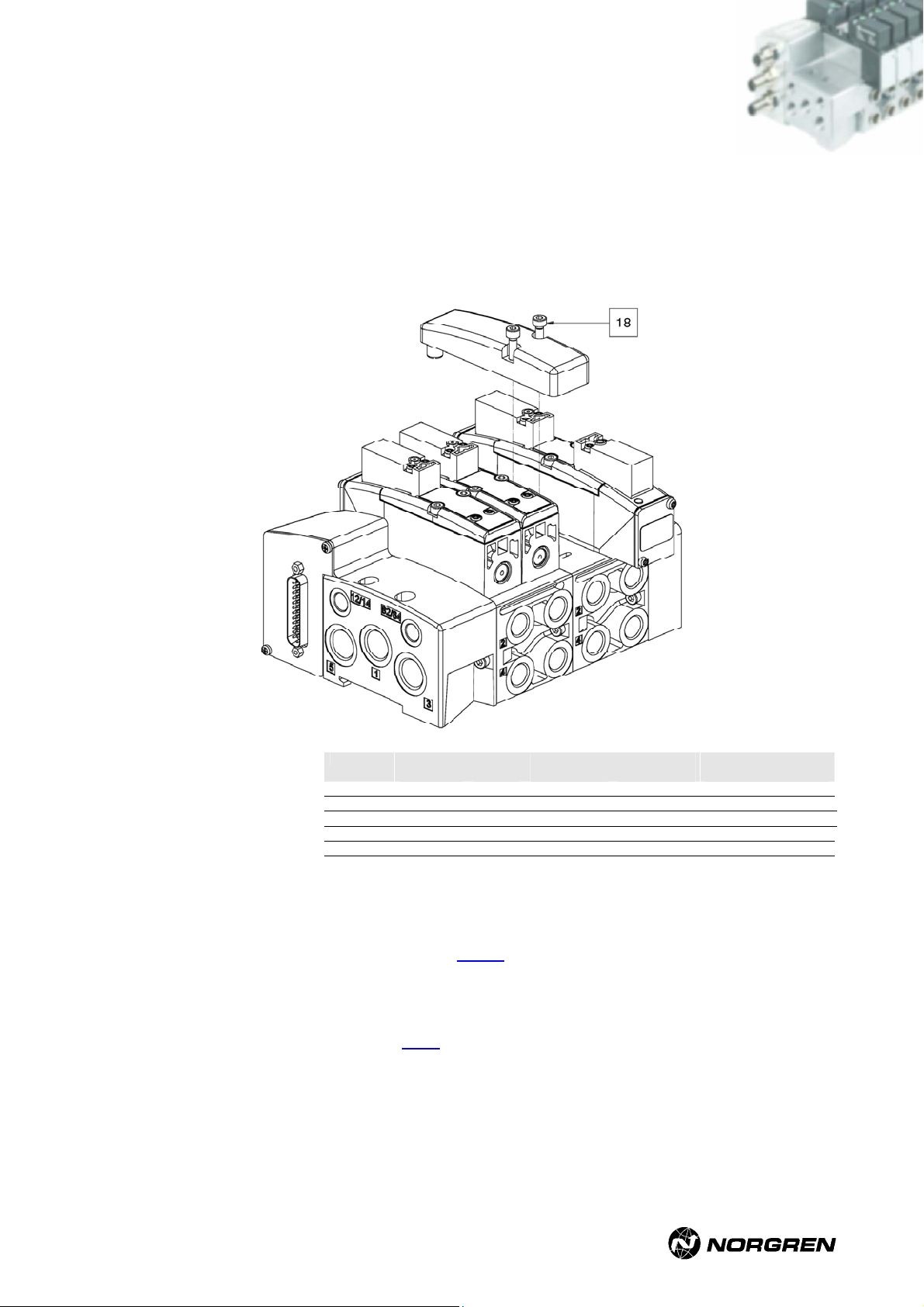
4. Lastly, mount the valves, sandwich plates, blanking plates and/or intermediate
supply/exhaust modules.
Valves:
1. Ensure valve body gasket is fitted on the bottom of the valve. Place valve onto the
modular sub-base aligned to the interface. Use plug-in connection as positioning point.
2. VS26 only: Orientate straight flange of the U-washers towards the outer edge of the
valve.
3. Tighten the valve mounting screws (two per valve) with the specified torque. If you are
using a power screwdriver, consider the maximum speed allowed.
Screw Type
(thread)
12 M3x40 VS18 1.1 – 1.5 9.73 – 13.27 1100
12 M4x42 VS26 1.2 – 1.6 10.62 – 14.16 1100
VS2672926-KG00E_05/07 Page 19/97
Valve
seize
Tightening
torque in Nm
Tightening
torque in Ibs
Max. screw driver
speed in r.p.m.
Page 20
VS18/VS26 MAINTENANCE & INSTRUCTION BOOKLET
Blanking plate and/or intermediate supply/exhaust module (ISEM):
1. Ensure gasket is fitted on the bottom of the blanking plate or ISEM. Place blanking plate
or ISEM onto the modular sub-base aligned to the interface.
2. Tighten valve mounting screws (two per blanking plate/ISEM) with the specified torque.
If you are using a power screwdriver consider the maximum speed allowed.
Screw Type
(thread)
18 M3x14 VS18 0.8 – 0.9 7.08 – 7.96 1100
18 M4x16 VS26 1.0 – 1.1 8.85 – 9.73 1100
Screw type used with ISEM:
M3x22 VS18 0.8 – 0.9 7.08 – 7.96 1100
M4x25 VS26 1.0 – 1.1 8.85 – 9.73 1100
Valve
seize
Tightening
torque in Nm
Tightening
torque in Ibs
Max. screw driver
speed in r.p.m.
Sandwich plates: Please refer to section
5.1.10
5. Having assembled the complete valve island, it is possible to mount it on a DIN-rail. For
instructions please refer to section
VS2672926-KG00E_05/07 Page 20/97
5.1.8.
Page 21

VS18/VS26 MAINTENANCE & INSTRUCTION BOOKLET
5.1.5 Valve identification labels
When purchasing assembled valve islands from Norgren, valve
identification labels are included. These labels are intended for the top
of the pilot valves and provide sufficient space for text appropriate to
your application.
Spare labels can also be ordered at Norgren as a set of 10 pieces.
Order number for VS18 as well as VS26 is VS2672905-KG00.
The labels are AVERY standard labels (no. L6008) which can be ordered as DIN A4 sheets
(21 x 29.7 cm) by your local representative of AVERY/Zweckform.
VS2672926-KG00E_05/07 Page 21/97
Page 22
VS18/VS26 MAINTENANCE & INSTRUCTION BOOKLET
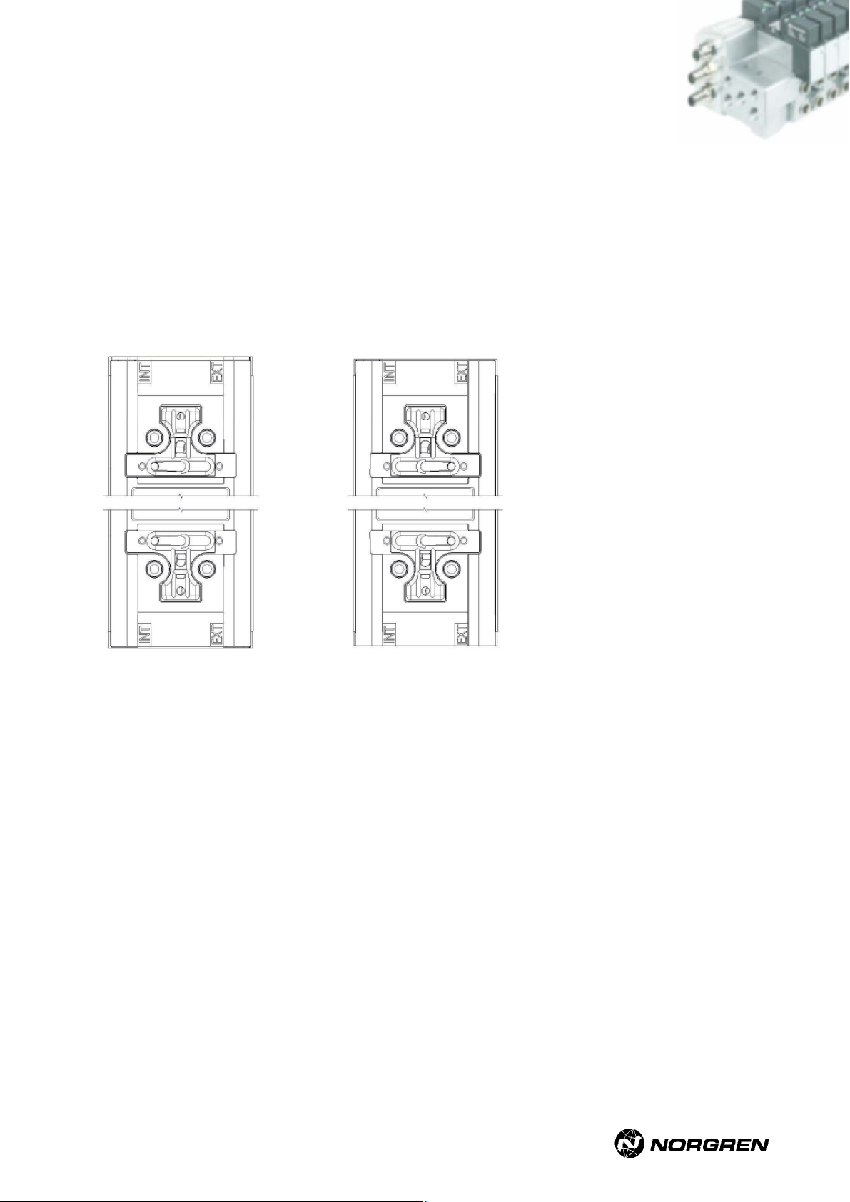
5.1.6 Internal/external pilot air supply
The position of the gasket between valve body and pilot valve defines and indicates pilot air
supply. Conversion between internal and external pilot supply occurs by flipping the red gasket.
Internal pilot air supply (fig. 1): from port 1
External pilot air supply (fig. 2): from port 12/14
In any case pilot exhaust air is collected and exhausted via port 82/84.
Figure 1 Figure 2
Solenoid 12 Solenoid 12
Solenoid 14 Solenoid 14
Such conversion in the field should occur only when minimum operating pressure is not
available at port 1. In these applications, the minimum operating pressure (or higher) is required
at port 12/14 on the end plate.
Note:
After flipping the gasket, data on the valve label (symbol and part number) are no longer
accurate. Furthermore, when changing valves or accessories (valve function, sandwich plate,
etc.) on a valve island, the part number on the label will no longer correspond to the
configuration. If you order the valve island based on the Norgren part number, the original
configuration will be delivered.
VS2672926-KG00E_05/07 Page 22/97
Page 23
VS18/VS26 MAINTENANCE & INSTRUCTION BOOKLET
5.1.7 Multi pressure
Tools:
VS18: Hexagon wrench key 2.5mm
VS26: Hexagon wrench key 3mm
By assembling blanking discs in ports 1, 3 and/or 5 as well as 12/14 you have the possibility to
porting different pressures.
1. Install blanking discs depending on required pressure isolation requirements during the
assembly of the modular sub-bases.
2. Generate pressure supply by connecting left and right end plate. Additionally, you have the
possibility to mount an intermediate supply/exhaust module on a valve station.
VS2672926-KG00E_05/07 Page 23/97
Screw Type
(thread)
11 M3x10 VS18 0.8 – 0.9 7.08 – 7.96 1100
11 M4x12 VS26 1.0 – 1.1 8.85 – 9.73 1100
20 M3x22 VS18 0.8 – 0.9 7.08 – 7.96 1100
20 M4x25 VS26 1.0 – 1.1 8.85 – 9.73 1100
Valve
seize
Tightening
torque in Nm
Tightening
torque in Ibs
Max. screw driver
speed in r.p.m.
Page 24
VS18/VS26 MAINTENANCE & INSTRUCTION BOOKLET
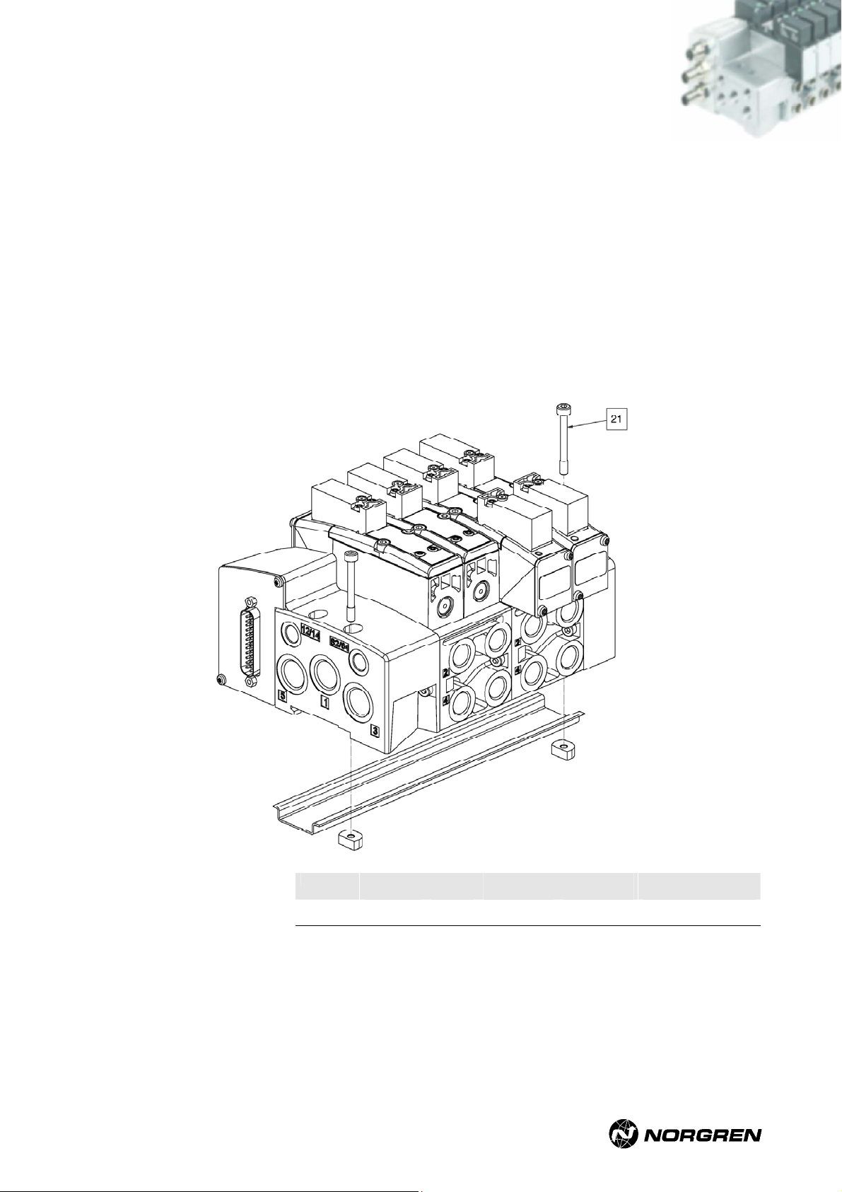
5.1.8 DIN-rail assembly
Tool:
VS18/VS26: Hexagon wrench key 3mm
1. Insert screws on the left and right end plates and position below the mounting nuts. (Screws
and mounting nuts are included in the DIN-rail mounting kit.) Tighten screws two revolutions
in the mounting nuts.
2. Place the valve island on the DIN-rail. Orientate straight flange of the mounting nuts towards
the DIN-rail.
3. Push the valve island on the DIN-rail and tighten screws with the specified torque. Check
the fit of the valve island.
VS2672926-KG00E_05/07 Page 24/97
Screw Type
(thread)
21 M4x36 VS18/
Valve
seize
VS26
Tightening
torque in Nm
1.0 – 1.1 8.85 – 9.73 1100
Tightening
torque in Ibs
Max. screw driver
speed in r.p.m.
Page 25
VS18/VS26 MAINTENANCE & INSTRUCTION BOOKLET
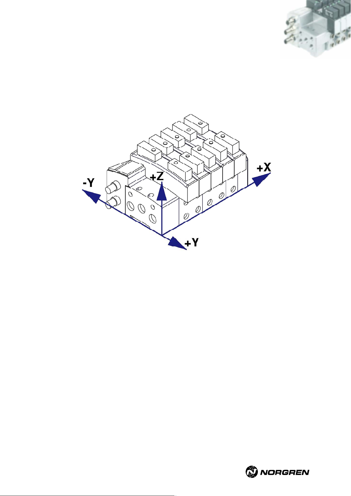
5.1.9 Installation instruction in case of raised vibrations
In case of vibrations of about 5g (at 60 Hz to 150 Hz) it is strongly recommended to mount
VS26 valve islands with more than 10 valve stations that main vibration load is in x-axis or
alternatively in y-axis.
VS2672926-KG00E_05/07 Page 25/97
Page 26

VS18/VS26 MAINTENANCE & INSTRUCTION BOOKLET
5.1.10 Sandwich plates
Tools:
VS18: Hexagon wrench keys 2mm and 2.5mm
VS26: Hexagon wrench key 3mm
1. Ensure gasket is fitted on the bottom of the sandwich plate. Mount sandwich plate onto the
sub-base aligned to the interface. Use plug-in connection as positioning point. Tighten
mounting screws (two per sandwich plate) with the specified torque. If you are using a
power screwdriver consider the maximum speed allowed.
2. Ensure valve body gasket is fitted on the bottom of the valve. Place valve onto the sandwich
plate aligned to the interface. Use plug-in connection as positioning point.
3. VS26 only: Orientate straight flange of the U-washers towards the outer edge of the valve.
4. Tighten valve mounting screws (two per valve) with the specified torque. If you are using a
power screwdriver consider the maximum speed allowed.
see figure on the following page
Note:
If threads of the sandwich plate are damaged by Allen wrench, this might affect the sealing
performance.
When changing valves or accessories (valve function, sandwich plate, etc.) on a valve island,
the part number on the label will no longer correspond to the configuration. If you order the
valve island based on the Norgren part number, the original configuration will be delivered.
VS2672926-KG00E_05/07 Page 26/97
Page 27
VS18/VS26 MAINTENANCE & INSTRUCTION BOOKLET
Screw Type
(thread)
24 M3x40 VS18 1.1 – 1.5 9.73 – 13.27 1100
24 M4x42 VS26 1.2 – 1.6 10.62 – 14.16 1100
19 M3x8 VS18 0.8 – 0.9 7.08 – 7.96 1100
19 M4x10 VS26 1.0 – 1.1 8.85 – 9.73 1100
Note: With all sandwich plate accessories will be used the same screw type.
Valve
seize
Tightening
torque in Nm
Tightening
torque in Ibs
Max. screw driver
speed in r.p.m.
VS2672926-KG00E_05/07 Page 27/97
Page 28

VS18/VS26 MAINTENANCE & INSTRUCTION BOOKLET
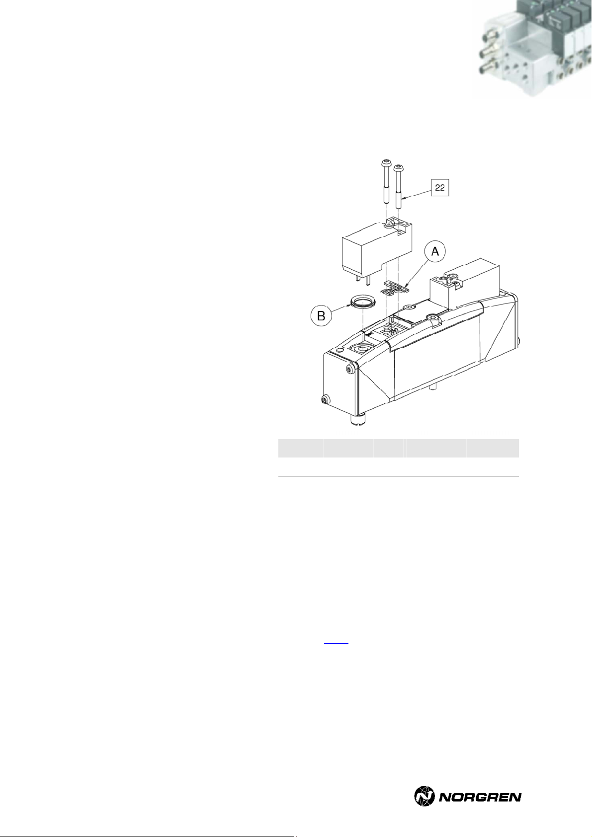
5.1.11 Replacement of valves
Tools:
VS18 Hexagon wrench key 2.5mm
VS26 Hexagon wrench key 3mm
1. Loosen existing valve mounting screws (two per valve) by turning counter-clockwise and
remove valve vertical to the top.
2. Ensure valve body gasket is fitted on the bottom of the new valve. Place new valve onto the
modular sub-base aligned to the interface. Use plug-in connection as positioning point.
3. VS26 only: Orientate straight flange of the U-washers towards the outer edge of the valve.
4. Tighten valve mounting screws (two per valve) with the specified torque. If you are using a
power screwdriver consider the maximum speed allowed.
Note:
Screw Type
(thread)
12 M3x40 VS18 1.1 – 1.5 9.73 – 13.27 1100
12 M4x42 VS26 1.2 – 1.6 10.62 – 14.16 1100
Valve
seize
Tightening
torque in Nm
Tightening
torque in Ibs
Max. screw driver
speed in r.p.m.
To avoid failures and/or use of valves with not allowed specification, you have to make sure that
the voltage of the new valve complies to the old one.
When changing valves or accessories (valve function, sandwich plate, etc.) on a valve island,
the part number on the label will no longer correspond to the configuration. If you order the
valve island based on the Norgren part number, the original configuration will be delivered.
VS2672926-KG00E_05/07 Page 28/97
Page 29
VS18/VS26 MAINTENANCE & INSTRUCTION BOOKLET
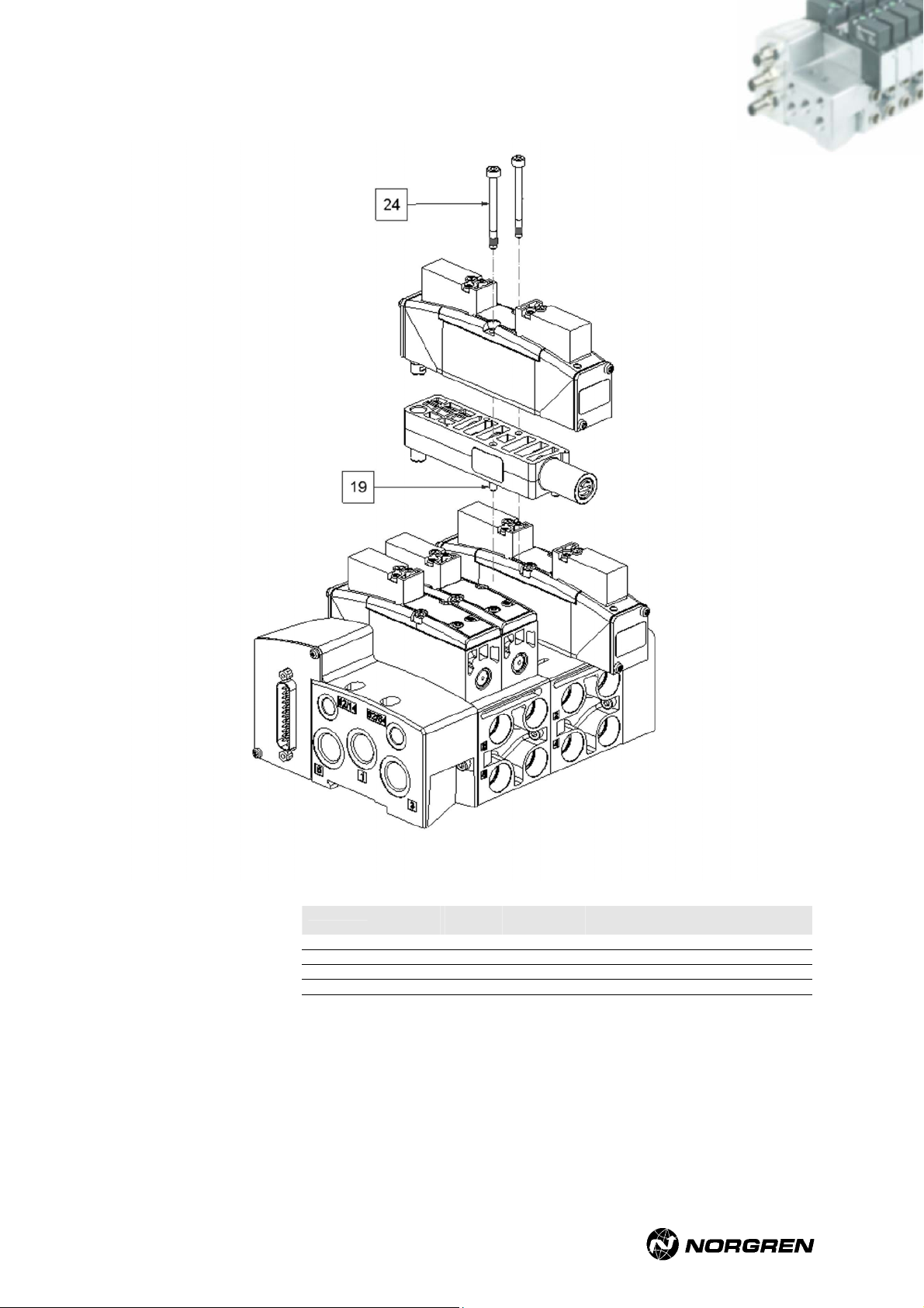
5.1.12 Replacement of pilot valves
Tool:
VS18/VS26: Socket screw key X10
1. Loosen existing pilot valve screws (two per
pilot valve) by turning counter-clockwise.
2. Important: Check and keep in mind the
position of the gasket (A) between valve
body and pilot valve (internal or external pilot
air supply) to make sure placing the new
gasket is set for the appropriate pilot type.
3. Remove pilot valve, V-ring (B) and gasket
(A).
4. Place new V-ring (B) and new gasket (A).
Consider now the position of the gasket (A)
(internal or external pilot air supply).
5. Place new pilot valve. Important: Turn new
thread moulded pilot valve screws (two per
pilot valve) by hand in the existing threads for
safe seizing to avoid damaging the existing
thread. Tighten the screws then with the
specified torque. Do not use a power
screwdriver!
Screw Type
(thread)
22 M3x24 VS18/
Valve
seize
VS26
Tightening
torque in Nm
0.9 – 1.0 7.96 – 8.85
Tightening
torque in Ibs
Note:
To avoid failures and/or use of valves with not allowed specification, you have to make sure that
the voltage of the new pilot valve complies to the old one.
When changing valves or accessories (valve function, sandwich plate, etc.) on a valve island,
the part number on the label will no longer correspond to the configuration. If you order the
valve island based on the Norgren part number, the original configuration will be delivered.
The pilot valve set includes:
• 1 pilot valve
• 1 gasket
• 1 V-ring
• 2 pilot valve screws
For ordering information on pilot valves refer to section
5.2.2.
VS2672926-KG00E_05/07 Page 29/97
Page 30
VS18/VS26 MAINTENANCE & INSTRUCTION BOOKLET
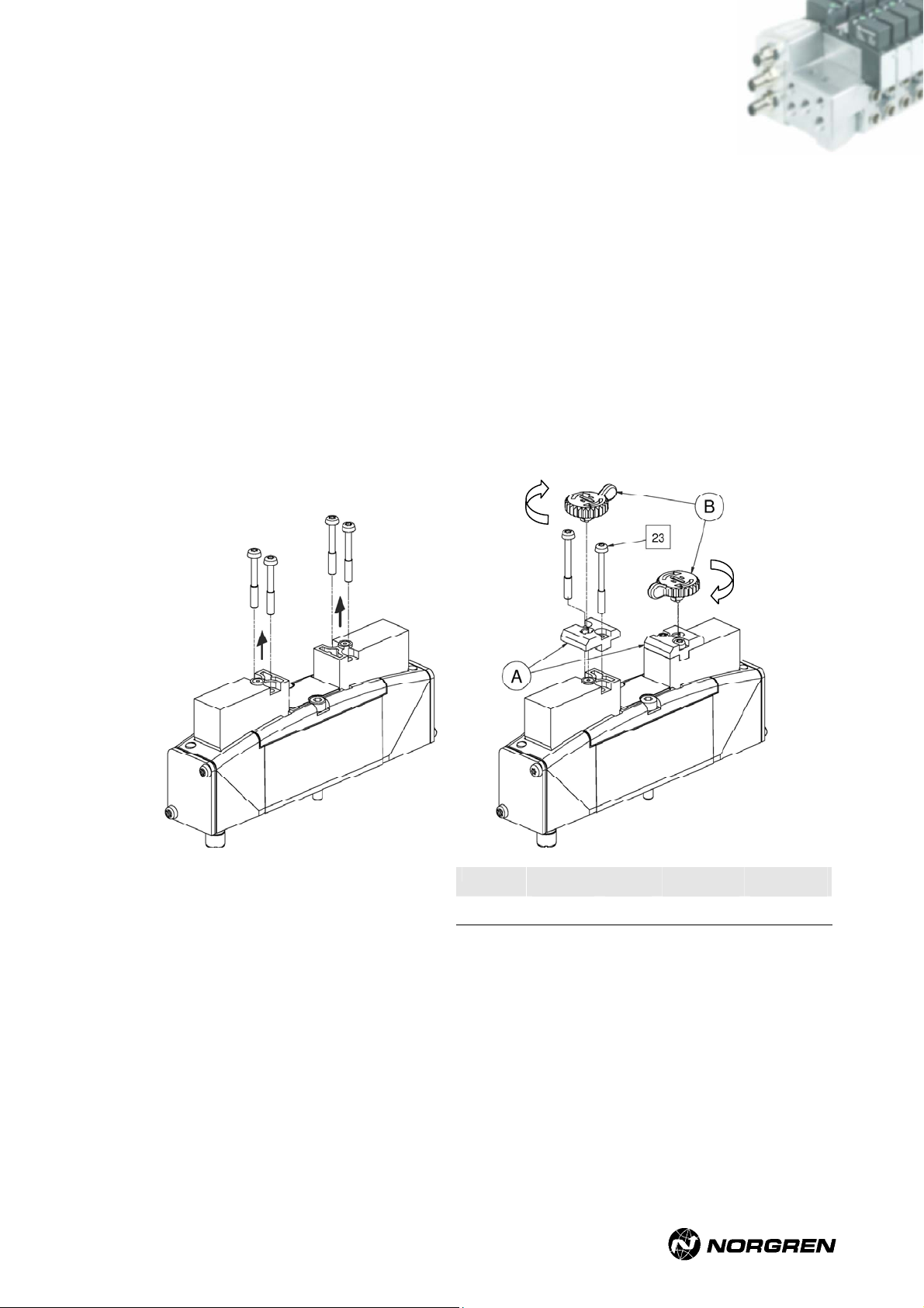
5.1.13 Manual override set-up kit
Tool:
VS18/VS26: Socket screw key X10
Use the manual override set-up kit to lock a non-locking manual override (excluding extended
manual override) as follows:
1. Remove existing pilot valve screws by turning counter-clockwise.
2. Put the adapter (A) on the pilot valve and mount it with the socket screws which are included
in the kit. Important: Turn thread moulded pilot valve screws (two per adapter) by hand in
the existing threads for safe seizing to avoid damaging the existing thread. Tighten the
screws then with the specified torque. Do not use a power screwdriver!
3. Put the key (B) on the adapter (A).
4. For operating the manual override kit, push and turn the key (B) clockwise.
Screw Type
(thread)
23 M3x29 VS18/
Valve
seize
VS26
Tightening
torque in Nm
0.9 – 1.0 7.96 – 8.85
Tightening
torque in Ibs
Note:
The key is provided for commissioning of the valve island only. If the key is left on the valve in
the operated position, the valve is switched on continually.
When changing valves or accessories (valve function, sandwich plate, etc.) on a valve island,
the part number on the label will no longer correspond to the configuration. If you order the
valve island based on the Norgren part number, the original configuration will be delivered.
The manual override set-up kit includes:
• 1 adapter
• 2 socket screws
• 1 key
VS2672926-KG00E_05/07 Page 30/97
Page 31

VS18/VS26 MAINTENANCE & INSTRUCTION BOOKLET
5.1.14 Blanking plug for base connector hole
For some applications an actuation of hard-wired valves on VS base (eg. safety function) is
required. The assembly of Mini ISO valves on VS sub-bases is possible due to the same
pneumatical interface. In these cases, the base connector hole is open. The IP65 blanking plug
protects PCB from dirt and humidity.
VS2672926-KG00E_05/07 Page 31/97
Page 32

VS18/VS26 MAINTENANCE & INSTRUCTION BOOKLET
5.2 MAINTENANCE
5.2.1 Lubrication
VS18/VS26 valves are pre-lubricated for life on assembly, but where air line lubricants are
required for pneumatic actuators or other driven devices, the following products are
recommended:
• Klüber Airpress 32
• Castrol Hyspin AWS 32
• Mobil Gargoyle Arctic Oil (Light)
• Mobil DTE 24
• Mobil DTE Light Oil
• Shell Tellus 22
• Shell Tellus 37
• Smallman Crown 10
For low temperatures (+5°C until –15°C) the following oils are recommended:
• Klüber Airpress 16
• Mobil SHL 264
• Duckhams Zeroflo 32
Note:
• If the air supply is lubricated, then lubrication must be supplied for the life of the product.
• Please consider the compatibility of the oil you use with the materials of the valve island.
VS2672926-KG00E_05/07 Page 32/97
Page 33

VS18/VS26 MAINTENANCE & INSTRUCTION BOOKLET
5.2.2 Spare parts
Pilot valves VS18/VS26:
Part no. Description Voltage Manual override
VS2672930-KG00 Pilot valve
including screws, gasket and V-ring
VS2672932-KG00 Pilot valve
including screws, gasket and V-ring
VS2672934-KG00 Pilot valve
including screws, gasket and V-ring
VS2672931-KG00 Pilot valve
including screws, gasket and V-ring
VS2672933-KG00 Pilot valve
including screws, gasket and V-ring
VS2672935-KG00 Pilot valve
including screws, gasket and V-ring
Spare parts for VS18/VS26 valves:
Part no. Description
94.00759 Valve body gasket VS26
94.00907 Valve body gasket VS18
77.01140 Coated valve mounting screws VS26
77.01143 Coated valve mounting screws VS18
94.00785 U-washers VS26
Spare parts for VS18/VS26 sub-bases and end plates:
24V DC 1.2W Push only
24V DC 1.2W Push & turn
24V DC 1.2W Extended, push only
115V AC 1.5VA Push only
115V AC 1.5VA Push & turn
115V AC 1.5VA Extended, push only
Part no. Description
77.31106 Hexagon socket screw M4x12 (VS26)
77.31055 Hexagon socket screw M3x10 (VS18)
94.00815 Gasket VS26
94.01015 Gasket VS18
94.00816 Connector-kit gasket on end plate VS18/VS26
VS2672926-KG00E_05/07 Page 33/97
Page 34

VS18/VS26 MAINTENANCE & INSTRUCTION BOOKLET
6 SINGLE STATION SUB-BASE
6.1 GENERAL INFORMATION
VS18/VS26 offers single station sub-bases for valves located remotely from valve island.
Below listed connectors are available for the electrical connection to the VS18/VS26 single
station sub-base. Please refer to the indicated section for detailed information on these.
• M12 connector Section
• NPTF1/2” conduit entry with flying leads Section
Please see information on assembly of valve and sandwich plates in section
6.1.1 24V DC power supply
VS18/VS26 single station sub-base 24V DC versions are designed to be used with a protective
extra low voltage (PELV) power supply (UL Class 2 Supply only). Therefore, the power supply
used must meet the IEC standard 742/EN60742/VDE 0551 (PELV).
6.1.2 115V AC power supply
6.2
6.3
5.1.4.
VS18/VS26 single station sub-base 115V AC versions correspond to the protection class I.
Connection of the protective earth (PE) ground is required.
6.1.3 Max current load on valve connectors with 24V DC
Imax = 60mA * n
n = number of energized solenoids
6.1.4 Max current load on valve connectors with 115V AC
Imax = 13mA * n
n = number of energized solenoids
VS2672926-KG00E_05/07 Page 34/97
Page 35

VS18/VS26 MAINTENANCE & INSTRUCTION BOOKLET
6.2 VARIANT WITH M12 CONNECTOR
The single station sub-base with M12 connector is available with G or NPTF pneumatic ports.
With the M12 connector, the power supply has to be 24V DC.
6.2.1 Pin assignment (acc. VDMA 24571)
Pin no. Function
1 not used
2 Signal for solenoid 12
3 Common for solenoid 12 and 14
4 Signal for solenoid 14
Looking into node connectors
Male
VS2672926-KG00E_05/07 Page 35/97
Page 36

VS18/VS26 MAINTENANCE & INSTRUCTION BOOKLET
6.3 VARIANT WITH NPTF1/2“ CONDUIT WITH FLYING LEADS
The single station sub-base with NPTF1/2“ conduit with flying leads is available with
G pneumatic ports only.
The power supply can be 24V DC or 115V AC. If you use 115V AC, connection of the protective
earth (PE) ground is required.
6.3.1 Wiring information
Wire colour Function
Green Earth
Yellow Signal for solenoid 12
Black Common for solenoid 12 and 14
Red Signal for solenoid 14
VS2672926-KG00E_05/07 Page 36/97
Page 37

VS18/VS26 MAINTENANCE & INSTRUCTION BOOKLET
7 MULTIPOLE
7.1 GENERAL INFORMATION
VS18/VS26 Multipole valve islands are intended for direct connection to a control system output
device. The system is designed for either PNP-switching (common negative anode) and NPNswitching (common positive anode).
VS18/VS26 Multipole valve islands consist of a minimum two valve stations. The maximum
number of valve stations is 20 (40 solenoids). You have to consider the maximum number of
possible valve stations of each Multipole connector. See section
expansion of the valve island.
Below listed connectors are available for the electrical connection to the VS18/VS26 Multipole
valve islands. Please refer to the indicated section for detailed information on these.
• D-Sub 9-, 15-, 25- or 44-pin Section
• NPTF1“ Conduit entry with terminals Section
• M23 19-pin connector Section
7.2
7.3
7.4
7.1.1 24V DC power supply
9 for information of field
VS18/VS26 Multipole 24V DC versions are designed to be used with a protective extra low
voltage (PELV) power supply (UL Class 2 Supply only). Therefore, the power supply used must
meet the IEC standard 742/EN60742/VDE 0551 (PELV).
7.1.2 115V AC power supply
VS18/VS26 Multipole 115V AC versions correspond to the protection class I. Connection of the
protective earth (PE) ground is required.
7.1.3 Max current load on valve connectors with 24V DC
Imax = 60mA * n
n = number of energized solenoids
7.1.4 Max current load on valve connectors with 115V AC
Imax = 13mA * n
n = number of energized solenoids
VS2672926-KG00E_05/07 Page 37/97
Page 38

VS18/VS26 MAINTENANCE & INSTRUCTION BOOKLET
7.2 VARIANTS WITH D-SUB CONNECTORS
The D-Sub connector is available in many sizes:
D-Sub 9-pin max. 4 valve stations (8 solenoids)
D-Sub 15-pin max. 7 valve stations (14 solenoids)
D-Sub 25-pin max. 12 valve stations (24 solenoids)
D-Sub 44-pin min. 8 valve stations, max. 20 valve stations (40 solenoids)
With all D-Sub connectors, the power supply has to be 24V DC.
1)
special D-Sub 44-pin cable with 42 assigned pins also available
7.2.1 D-Sub assembly / Installation of PCB
Tool:
VS18/VS26 Philips screwdriver size 1
1. Important: Make sure valves are not already mounted on the valve island, because the
Multipole PCB (A) could become damaged during assembly.
1)
2. Ensure connector-kit gasket is fitted on the left end plate.
3. Insert the Multipole PCB, which is fitted on the Multipole E-connector-kit (A), in the left
groove of the left end plate and the modular sub-bases. Check to make sure the plug-in
connection on the PCB is centred with the orifice to the valve interface.
4. Mount the Multipole E-connector-kit (A) with two mounting screws on the left end plate.
Tighten the screws with the specified torque. If you are using a power screwdriver consider
the maximum speed allowed.
VS2672926-KG00E_05/07 Page 38/97
Screw Type
(thread)
13 M3x8 VS18/
Valve
seize
VS26
Tightening
torque in Nm
0.8 – 0.9 7.08 – 7.96 1100
Tightening
torque in Ibs
Max. screw driver
speed in r.p.m.
Page 39

VS18/VS26 MAINTENANCE & INSTRUCTION BOOKLET
7.2.2 Pin assignment
D-Sub 9-pin
Pin no. Wire colour Socket Pilot Station
1 white Solenoid 1-a 14 1
2 brown Solenoid 2-a 14 2
3 green Solenoid 3-a 14 3
4 yellow Solenoid 4-a 14 4
5 grey Solenoid 1-b 12 1
6 pink Solenoid 2-b 12 2
7 blue Solenoid 3-b 12 3
8 red Solenoid 4-b 12 4
9 black Common - -
Colour code according to DIN 47100
D-Sub 15-pin
Male
Looking into node connectors
Pin no. Wire colour Socket Pilot Station
1 white Solenoid 1-a 14 1
2 brown Solenoid 2-a 14 2
3 green Solenoid 3-a 14 3
4 yellow Solenoid 4-a 14 4
5 grey Solenoid 5-a 14 5
6 pink Solenoid 6-a 14 6
7 blue Solenoid 7-a 14 7
8 red Solenoid 1-b 12 1
9 black Solenoid 2-b 12 2
10 violet Solenoid 3-b 12 3
11 grey/pink Solenoid 4-b 12 4
12 red/blue Solenoid 5-b 12 5
13 white/green Solenoid 6-b 12 6
14 brown/green Solenoid 7-b 12 7
15 white/yellow Common - -
Colour code according to DIN 47100
Male
Looking into node connectors
VS2672926-KG00E_05/07 Page 39/97
Page 40

VS18/VS26 MAINTENANCE & INSTRUCTION BOOKLET
D-Sub 25-pin
Pin no. Wire colour Socket Pilot Station
1 white Solenoid 1-a 14 1
2 brown Solenoid 2-a 14 2
3 green Solenoid 3-a 14 3
4 yellow Solenoid 4-a 14 4
5 grey Solenoid 5-a 14 5
6 pink Solenoid 6-a 14 6
7 blue Solenoid 7-a 14 7
8 red Solenoid 8-a 14 8
9 black Solenoid 9-a 14 9
10 violet Solenoid 10-a 14 10
11 grey/pink Solenoid 11-a 14 11
12 red/blue Solenoid 12-a 14 12
13 white/green Common - 14 brown/green Solenoid 1-b 12 1
15 white/yellow Solenoid 2-b 12 2
16 yellow/brown Solenoid 3-b 12 3
17 white/grey Solenoid 4-b 12 4
18 grey/brown Solenoid 5-b 12 5
19 white/pink Solenoid 6-b 12 6
20 pink/brown Solenoid 7-b 12 7
21 white/blue Solenoid 8-b 12 8
22 brown/blue Solenoid 9-b 12 9
23 white/red Solenoid 10-b 12 10
24 brown/red Solenoid 11-b 12 11
25 white/black Solenoid 12-b 12 12
Colour code according to DIN 47100
Male
Looking into node connectors
VS2672926-KG00E_05/07 Page 40/97
Page 41

VS18/VS26 MAINTENANCE & INSTRUCTION BOOKLET
D-Sub 44-pin
Pin no. Wire colour Socket Pilot Station
1 white Solenoid 1-a 14 1
Male
2 brown Solenoid 2-a 14 2
3 green Solenoid 3-a 14 3
4 yellow Solenoid 4-a 14 4
5 grey Solenoid 5-a 14 5
6 pink Solenoid 6-a 14 6
7 blue Solenoid 7-a 14 7
8 red Solenoid 8-a 14 8
9 black Solenoid 9-a 14 9
10 violet Solenoid 10-a 14 10
11 grey/pink Solenoid 11-a 14 11
12 red/blue Solenoid 12-a 14 12
13 white/green Solenoid 13-a 14 13
14 brown/green Solenoid 14-a 14 14
15 white/yellow Solenoid 15-a 14 15
16 yellow/brown Solenoid 1-b 12 1
Looking into node connectors
17 white/grey Solenoid 2-b 12 2
18 grey/brown Solenoid 3-b 12 3
19 white/pink Solenoid 4-b 12 4
20 pink/brown Solenoid 5-b 12 5
21 white/blue Solenoid 6-b 12 6
22 brown/blue Solenoid 7-b 12 7
23 white/red Solenoid 8-b 12 8
24 brown/red Solenoid 9-b 12 9
25 white/black Solenoid 10-b 12 10
26 brown/black Solenoid 11-b 12 11
27 grey/green Solenoid 12-b 12 12
28 yellow/grey Solenoid 13-b 12 13
29 pink/green Solenoid 14-b 12 14
30 yellow/pink Solenoid 15-b 12 15
31 green/blue Solenoid 16-a 14 16
32 yellow/blue Solenoid 16-b 12 16
33 - not used - 34 - not used - 35 - not used - 36 - not used - 37 - not used - 38 - not used - 39 - not used - 40 - not used - 41 - not used - 42 - not used - 43 blue/black 1)Common - 44 red/black 1)Common - -
Colour code according to DIN 47100
1)
The Norgren D-Sub 44-pin cables do not have 44 wires, but only 34 wires. Therefore, the wires associated with pins
1 through 32 are according to DIN 47100, wires 43 and 44 differ from the standard and are coloured in green/black
and yellow/black.
VS2672926-KG00E_05/07 Page 41/97
Page 42

VS18/VS26 MAINTENANCE & INSTRUCTION BOOKLET
7.3 VARIANT WITH NPTF1” CONDUIT ENTRY WITH TERMINALS
The NPTF1“ conduit entry with terminals is composed of a body with a NPTF1“ thread for use
with flexible or fixed conduit. In this body exists a terminal block for connecting all necessary
wires.
The NPTF1“ conduit entry is valid for a valve island with maximum 12 valve stations (24
solenoids).
The power supply can be 24V DC or 115V AC. If you use 115V AC, connection of the protective
earth (PE) ground is required.
7.3.1 NPTF1” conduit entry with terminals assembly / Installation of PCB
Tools:
VS18/VS26: Philips screwdriver size 1 and
screwdriver size 1
1. Important: Make sure valves are not already mounted on the valve island, because the
Multipole PCB (B) could become damaged during assembly.
2. Remove the terminal block (C) from the body (A) by loosing the two plastic screws as well
as the two earth contact screws with serrated lock washers.
Screw Type
14 M3x12 VS18/
15 M3x10 VS18/
16 M3x6 VS18/
(thread)
Valve
seize
VS26
VS26
VS26
Tightening
torque in Nm
0.8 – 0.9 7.08 – 7.96 1100
0.1 0.88 Tighten by hand!
0.5 4.42 750 or
Tightening
torque in Ibs
Max. screw driver
speed in r.p.m.
tighten by hand!
VS2672926-KG00E_05/07 Page 42/97
Page 43

VS18/VS26 MAINTENANCE & INSTRUCTION BOOKLET
3. Use the schematic in section 7.3.2 for wiring. Unlock corresponding square clamping on the
terminal block by pushing the screwdriver on the diagonal trench. Insert one wire into the
clamp. By removing the screwdriver, the wire is fixed. Repeat this step with each additional
wire.
4. Important: Connect common wire (COM) and protective earth (PE) ground wire!
5. Remount the terminal block (C) with the two plastic screws (15) on the body (A). Turn plastic
screws by hand in the existing threads and tighten then
by hand. Note: Use of plastic screws
is required because the minimum distance to the body (electrical safety) does not allow
metal screws.
6. The two closed mounting holes are made for the earthing of the Multipole PCB (B). Mount
the two screws (16) with the serrated lock washers. The serrated lock washers give a safe
contact even if the screws oxidise. Tighten the screws with the specified torque. If you are
using a power screwdriver consider the maximum speed allowed.
7. Insert the Multipole PCB (B) in the left groove of the left end plate and the modular subbases. Check to make sure the plug-in connection on the PCB is centred with the orifice to
the valve interface.
8. Ensure connector-kit gasket is fitted on the left end plate.
9. Plug the terminal block (C) in the body (A) on the Multipole PCB (B).
10. Mount the body (A) with two mounting screws on the left end plate. Tighten the screws with
the specified torque. If you are using a power screwdriver consider the maximum speed
allowed.
Screw Type
(thread)
14 M3x12 VS18/
VS2672926-KG00E_05/07 Page 43/97
Valve
seize
VS26
Tightening
torque in Nm
0.8 – 0.9 7.08 – 7.96 1100
Tightening
torque in Ibs
Max. screw driver
speed in r.p.m.
Page 44

VS18/VS26 MAINTENANCE & INSTRUCTION BOOKLET
7.3.2 Pin assignment
Clamp no. Socket Pilot Station
C1 Solenoid 1-a 14 1
C2 Solenoid 2-a 14 2
C3 Solenoid 3-a 14 3
C4 Solenoid 4-a 14 4
C5 Solenoid 5-a 14 5
C6 Solenoid 6-a 14 6
C7 Solenoid 7-a 14 7
C8 Solenoid 8-a 14 8
C9 Solenoid 9-a 14 9
C10 Solenoid 10-a 14 10
C11 Solenoid 11-a 14 11
C12 Solenoid 12-a 14 12
C13 Solenoid 1-b 12 1
C14 Solenoid 2-b 12 2
C15 Solenoid 3-b 12 3
C16 Solenoid 4-b 12 4
C17 Solenoid 5-b 12 5
C18 Solenoid 6-b 12 6
C19 Solenoid 7-b 12 7
C20 Solenoid 8-b 12 8
C21 Solenoid 9-b 12 9
C22 Solenoid 10-b 12 10
C23 Solenoid 11-b 12 11
C24 Solenoid 12-b 12 12
C25 Common - C26 Common - C27 Earth - C28 Earth - -
Maximum wire size = AWG18
VS2672926-KG00E_05/07 Page 44/97
Page 45

VS18/VS26 MAINTENANCE & INSTRUCTION BOOKLET
7.4 VARIANT WITH M23 CONNECTOR
The M23 19-pin connector is valid for a valve island with maximum 8 valve stations (16
solenoids).
The power supply can be 24V DC or 115V AC. If you use 115V AC, connection of the protective
earth (PE) ground is required.
The M23 19-pin connector fulfils CNOMO standard E03.62.530.N. For more information on this
standard please refer to the CNOMO website
7.4.1 M23 assembly / Installation of PCB
Tool:
VS18/VS26 Philips screwdriver size 1
1. Important: Make sure valves are not already mounted on the valve island, because the
Multipole PCB (B) could become damaged during assembly.
www.cnomo.com.
2. Insert the Multipole PCB (B) in the left groove of the left end plate and the modular subbases. Check to make sure the plug-in connection on the PCB is centred with the orifice to
the valve interface.
3. Plug the connector of the M23 E-connector-kit (C) into the connector on the Multipole PCB
(B).
4. Ensure connector-kit gasket is fitted on the left end plate.
5. Mount the M23 E-connector-kit (C) with two mounting screws on the left end plate. Tighten
the screws with the specified torque. If you are using a power screwdriver consider the
maximum speed allowed.
Screw Type
(thread)
13 M3x8 VS18/
VS2672926-KG00E_05/07 Page 45/97
Valve
seize
VS26
Tightening
torque in Nm
0.8 – 0.9 7.08 – 7.96 1100
Tightening
torque in Ibs
Max. screw driver
speed in r.p.m.
Page 46

VS18/VS26 MAINTENANCE & INSTRUCTION BOOKLET
7.4.2 Pin assignment
Pin no. Wire colour Socket Pilot Station
1 White Solenoid 8-a 14 8
2 Brown (thin) Solenoid 6-a 14 6
3 Green Solenoid 4-a 14 4
4 Yellow Solenoid 2-b 12 2
5 Grey Solenoid 2-a 14 2
6 Blue (thick) Common - 7 Blue (thin) Solenoid 1-b 12 1
8 Red Solenoid 3-b 12 3
9 Black Solenoid 5-b 12 5
10 Violet Solenoid 7-b 12 7
11 Grey/Pink Solenoid 7-a 14 7
12 Yellow/Green Earth - 13 White/Green Solenoid 6-b 12 6
14 Brown/Green Solenoid 4-b 12 4
15 White/Yellow Solenoid 1-a 14 1
16 Yellow/Brown Solenoid 3-a 14 3
17 Pink Solenoid 5-a 14 5
18 Red/Blue Solenoid 8-b 12 8
19 Brown (thick) NOT USED - -
Male
Looking into node connectors
VS2672926-KG00E_05/07 Page 46/97
Page 47

VS18/VS26 MAINTENANCE & INSTRUCTION BOOKLET
8 FIELDBUS
8.1 GENERAL INFORMATION
VS18/VS26 Fieldbus valve islands range from a minimum of four valve stations to a maximum
of 16 valve stations (32 solenoids). The exception to this rule is AS-Interface (see section
Please refer to section
VS18/VS26 valve islands are available with below listed Fieldbus protocols. Please refer to the
indicated section for detailed information on these protocols.
• Profibus DP Section
• DeviceNet Section
• CANopen Section
• Interbus-S Section
• AS-Interface Section
• FD67 bus Section
VS18/VS26 Fieldbus valve islands contain electronic devices, which could be damaged through
electrostatic discharge. Therefore electrostatic precautions must be taken. Specifically, the
person assembling or configuring the valve island must be connected to an earth ground.
The valve island should be mounted on an earthed base to improve the EMC behaviour.
9 for information on field expansion of the valve island.
8.2
8.3
8.4
8.5
8.6
8.7
8.6).
VS2672926-KG00E_05/07 Page 47/97
Page 48

VS18/VS26 MAINTENANCE & INSTRUCTION BOOKLET
8.1.1 Power supply and pin assignment
VS18/VS26 Fieldbus valve islands are designed to be used with a protective extra low voltage
(PELV) power supply (UL Class 2 Supply only) according to IEC 364-4-41. As a result, an earth
connection for safety reasons is not required because the supply voltage is restricted to a
maximum of 42.2 volts even under fault conditions. However, the earth must be connected. It is
not a protective earth, but is required to provide EMC shielding.
The power supply of the Fieldbus valve islands (excluding the version with AS-Interface or
FD67 bus) are made by an 4-pin M12 connector. Using Profibus DP, a 5-pin 7/8“ connector is
also available.
M12 4-pin power connector for Fieldbus
Pin no. Function Tolerance Max. current
1 24 VB logic circuit supply +/-25% 300mA
2 24 VA valves +/-10%
3 0 volt -
1)
2)
4 Earth - -
Note:
Looking into node connectors
Male
Both DeviceNet and CANopen nodes do not use pin 1 of the M12 power connector. This is due
to the power for the logic circuit being drawn from the network connection. For details on pin
assignment please refer to sections
8.3.1 (DeviceNet) and 8.4.1 (CANopen).
Male
7/8” 5-pin power connector for Profibus DP
Pin no. Function Tolerance Max. current
1 - - 2 0 volt -
2)
3 Earth - 4 24 VA valves +/-10%
1)
5 24 VB logic circuit supply +/-25% 300mA
1)
Imax = 10mA + n * 60mA
n = number of energized solenoids
2)
Imax = IVA + IVB
Looking into node connectors
8.1.2 Max. current load on valve connectors
The digital outputs for activation the pilot valves are optimised for Norgren VS18/VS26 valves.
Among compliance of the following data, it is possible to use items from other manufacturers:
• Maximum current: I
• Limitation of the inductive interrupting to U < 40V
• Pin assignment according to ISO 15407-2
• Output voltage: U
max = 85mA (if VA = 24V DC)
output = Usupply – 0.9V
VS2672926-KG00E_05/07 Page 48/97
Page 49

VS18/VS26 MAINTENANCE & INSTRUCTION BOOKLET
8.1.3 Fieldbus assembly / Installation of PCBs (excluding AS-Interface and FD67
bus)
Tool:
VS18/VS26 Philips screwdriver size 1
1. Important: Make sure valves are not already mounted on the valve island, because the
output PCB (C) could become damaged during assembly.
2. Insert first output PCB (C) in the left groove of the left end plate and the modular sub-bases.
Check to make sure the plug-in connection on the PCB is centred with the orifice to the
valve interface.
3. Insert Fieldbus PCB (B) in the right groove of the left end plate and the modular sub-bases.
4. Plug the lowest connector of the Fieldbus E-connector-kit (A) into the connector on the
output PCB (C).
5. Plug the remaining connector(s) of the Fieldbus E-connector-kit (A) into the connector(s) on
the Fieldbus PCB (B).
6. Ensure connector-kit gasket is fitted on the left end plate.
7. Mount the Fieldbus E-connector-kit (A) with two mounting screws on the left end plate.
Tighten the screws with the specified torque. If you are using a power screwdriver consider
the maximum speed allowed.
8. Ensure gasket on the bottom of the LED window (D) is fitted and place the LED window on
the left end plate. Turn mounting screws by hand in the existing threads and tighten then
by
hand.
Screw Type
(thread)
13 M3x8 VS18/
17 M3x8 VS18/
VS2672926-KG00E_05/07 Page 49/97
Valve
seize
VS26
VS26
Tightening
torque in Nm
0.8 – 0.9 7.08 – 7.96 1100
0.4 3.54 Tighten by hand!
Tightening
torque in Ibs
Max. screw driver
speed in r.p.m.
Page 50

VS18/VS26 MAINTENANCE & INSTRUCTION BOOKLET
8.1.4 AS-Interface assembly / Installation of PCBs
Tool:
VS18/VS26 Philips screwdriver size 1
1. Important: Make sure valves are not already mounted on the valve island, because the ASInterface PCB (B) as well as the expansion PCB (C) could become damaged during
assembly.
2. Insert the AS-Interface PCB (B) in the middle groove of the left end plate and the modular
sub-bases. Consider, that the single station expansion PCB (C), different from the main
PCB (B), has to be inserted in the
bases. Check to make sure the plug-in connection on the PCB is centred with the orifice to
the valve interface.
3. Plug the lowest connector of the Fieldbus E-connector-kit (A) into the connector on the ASInterface PCB (B).
4. Plug the other connector of the Fieldbus E-connector-kit (A) into the upper connector on the
AS-Interface PCB (B).
left groove of the left end plate and the modular sub-
5. Ensure connector-kit gasket is fitted on the left end plate.
6. Mount the Fieldbus E-connector-kit (A) with two mounting screws on the left end plate.
Tighten the screws then with the specified torque. If you are using a power screwdriver
consider the maximum speed allowed.
7. Ensure gasket on the bottom of the LED window (D) is fitted and place the LED window on
the left end plate. Turn mounting screws by hand in the existing threads and tighten then
by
hand.
Screw Type
(thread)
13 M3x8 VS18/
17 M3x8 VS18/
Valve
seize
VS26
VS26
Tightening
torque in Nm
0.8 – 0.9 7.08 – 7.96 1100
0.4 3.54 Tighten by hand!
Tightening
torque in Ibs
Max. screw driver
speed in r.p.m.
VS2672926-KG00E_05/07 Page 50/97
Page 51

VS18/VS26 MAINTENANCE & INSTRUCTION BOOKLET
8.1.5 FD67 bus assembly / Installation of PCB
Tool:
VS18/VS26 Philips screwdriver size 1
1. Important: Make sure valves are not already mounted on the valve island, because the
output PCB (B) could become damaged during assembly.
2. Insert the output PCB (B) in the
left groove of the left end plate and the modular sub-bases.
Check to make sure the plug-in connection on the PCB is centred with the orifice to the
valve interface.
3. Look through the LED hole for mounting the FD67 E-connector-kit (A). Plug the connector of
the Fieldbus PCB which is mounted on the E-connector-kit (A) into the connector on the
output PCB (B).
4. Ensure connector-kit gasket is fitted on the left end plate.
5. Mount the FD67 E-connector-kit (A) with two mounting screws on the left end plate. Tighten
the screws then with the specified torque. If you are using a power screwdriver consider the
maximum speed allowed.
6. Ensure gasket on the bottom of the LED window (C) is fitted and place the LED window on
the left end plate. Turn mounting screws by hand in the existing threads and tighten then
by
hand.
Screw Type
(thread)
13 M3x8 VS18/
17 M3x8 VS18/
Valve
seize
VS26
VS26
Tightening
torque in Nm
0.8 – 0.9 7.08 – 7.96 1100
0.4 3.54 Tighten by hand!
Tightening
torque in Ibs
Max. screw driver
speed in r.p.m.
VS2672926-KG00E_05/07 Page 51/97
Page 52

VS18/VS26 MAINTENANCE & INSTRUCTION BOOKLET
8.2 PROFIBUS DP
Norgren Profibus DP Fieldbus systems conform to
DIN 19245 part 3.
Communication system: 2-wire RS485 hardware
communication protocol
Baud rate: 9.6 kBit/s to 12 MBit/s. Automatic detection.
Maximum nodes per network: 126
total number of I/O per network: 32256
Bus topology: Line
8.2.1 Profibus DP pin assignment
2 x M12 5-pin version (B-coded / IP65)
Pin no. Function
1 5VI isolated
2 Line A (green)
3 0VI isolated
4 Line B (red)
5 Shield
Threaded
joint
Shield
1 x D-Sub 9-pin version (IP40)
Pin no. Function
1 Shield
2 N/C
3 Line B (red) RxD / TxD-P
4 N/C
5 DGND (0VI) isolated
6 VP (5VI) isolated
7 N/C
8 Line A (green) Rxd / TxD-N
9 N/C
Male Female
Communication in Communication out
Looking into node connectors
Female
Looking into node connectors
VS2672926-KG00E_05/07 Page 52/97
Page 53

VS18/VS26 MAINTENANCE & INSTRUCTION BOOKLET
8.2.2 Profibus DP wiring
The bus line is specified in EN 50170 as line type A. It can be used as shown in the following
table. The table gives the bus parameters and line lengths of A and B type lines for comparison.
However it is recommended that only type A lines should be used, due to their expanded length
capabilities.
Line parameter
Parameter Line A Line B
Impedance in Ohm 135 to 165 100 to 130
Capacitance per unit length (pF/m) < 30 < 60
Loop resistance (Ohm/km) 110 Core diameter (mm) 0.64 > 0.53
Core cross section (mm2) > 0.34 > 0.22
Line lengths
Baud rate (kBit/s) 9.6 19.2 93.75 187.5 500 1‘500 12‘000
Line A (m) 1‘200 1‘200 1‘200 1‘000 400 200 100
Line B (m) 1‘200 1‘200 1‘200 600 200 - -
Calculating possible line lengths
The maximum admissible distance between two bus stations in each Profibus network can be
calculated as follows:
(NO_REP + 1) * Segment length
NO_REP = The maximum number of repeaters connected in series (depends on repeater type).
Example: The repeater manufacturer’s specifications allow nine repeaters to be connected in
series. The maximum distance between two bus stations at a data transfer rate of 1’500 kBit/s is
then as follows:
(9 + 1) * 200 m = 2’000 m
VS2672926-KG00E_05/07 Page 53/97
Page 54

VS18/VS26 MAINTENANCE & INSTRUCTION BOOKLET
Wiring termination
The active bus termination using a resistor combination avoids signal reflections during data
transfer and ensures a defined zero-signal voltage on the data lines when none of the stations
on the bus are active. Active termination must be provided at the beginning and end of each
RS485 bus segment.
5V (1)
390 Ω
Data Line - B(4)
220 Ω
Data Line - A( 2)
390 Ω
GND(3)
Line termination of wire A in acc. With EN 50 170
If the bus termination is missing, this can cause errors during data transfer. Problems can also
arise if too many bus terminators are fitted since each bus terminator also represents an
electrical load and reduces the signal levels and thus the signal-to-noise ratio. Too many or
missing bus terminators can also cause intermittent data transfer errors, particularly if the bus
segment is operated close to the specified limits for maximum numbers of stations, maximum
bus segment length and maximum data transfer rate.
The power required by the active bus termination is usually obtained through the bus connector
from stations connected to the bus. Alternative measures must be taken if there is no guarantee
that the power required by the bus termination is permanently provided while the bus is
operating. For example, in a particular installation the station providing the power to the bus
termination may need to be repeatedly switched off or removed from the bus for operational
reasons. In such cases, the bus termination should use an external power supply or a repeater
should be used for bus termination instead.
VS2672926-KG00E_05/07 Page 54/97
Page 55

VS18/VS26 MAINTENANCE & INSTRUCTION BOOKLET
8.2.3 Profibus DP address and baud rate setting
The VS18/VS26 Profibus DP valve island address can be set within the range 1 to 99 (rotary
switch) resp. 125 (software). To set the address, use the selector switches accessible by
removing the securing screw and lifting the hinged cover of the address switches. The two
rotary switches allow an address range of 1 to 99. The valve island needs a power reset to
accept a new address. When position 0 is selected on both switches the address may be set
through software via a capable master.
Default address = 125
Following are VS18/VS26 Profibus DP baud rates, which are detected automatically:
9.60 kBit/s 19.20 kBit/s 45.45 kBit/s 93.75 kBit/s
187.50 kBit/s 500.00 kBit/s 1.50 MBit/s 12.00 MBit/s
VS2672926-KG00E_05/07 Page 55/97
Page 56

VS18/VS26 MAINTENANCE & INSTRUCTION BOOKLET
8.2.4 Profibus DP output addressing
Data byte_0 Data byte_1 Data byte_2 Data byte_3
Valve no. ¨ 1 2 3 4 5 6 7 8 9 10 11 12 13 14 15 16
Data bits
Solenoid 14 0 2 4 6 8 10 12 14 16 18 20 22 24 26 28 30
Solenoid 12 1 3 5 7 9 11 13 15 17 19 21 23 25 27 29 31
Solenoids 14
Solenoids 12
Valve no.
Number of configured output bytes
The number of configured output bytes can be changed if required. The default setting is always
on the maximum (4 output bytes). To change the number of outputs you have to remove the
Fieldbus PCB and modify the DIP switch as follows:
1
2
O
N
switch1 0 0 1 1
switch2 0 1 0 1
output
bytes
1 2 3 4
Fieldbus PCB
VS2672926-KG00E_05/07 Page 56/97
Page 57

VS18/VS26 MAINTENANCE & INSTRUCTION BOOKLET
8.2.5 Diagnostics
The VS18/VS26 Profibus DP slave uses diagnostic telegrams as a high-priority response to
inform a master of its current state. The first 6 bytes contain the information specified by the
standard e.g. status of the state machine, correct/incorrect parameterisation and configuration.
Additionally, there is 1 byte of user diagnostics, which is used to show the state of the VA for the
valves. By monitoring the first bit of the user diagnostics byte the presence of the valve power
can be determined.
8.2.6 Profibus DP LED indicators
VB (green) – This LED will only be energised when 24 volts is applied to the electronics
power terminal of the power supply connector.
5V (green) – This LED will only be energised when a 24 volt supply is applied to the
electronic supply terminal of the power supply connector, indicating that the
logic circuit of the module is powered.
BA (green) – This LED indicates the status of the network traffic, indicating when network
packages are received.
VA (green) – This LED will only be energised when 24 volts is applied to the valve power
terminal of the power supply connector.
Indicator states during powering up and commissioning
Condition VB 5V BA VA
Power up on on off on
Changing address during
commissioning
Device in a stopped state on on off on
Device in an operation state on on on on
on on off on
8.2.7 Profibus DP commissioning
Due to the increasing number of compatible master controllers it would be impractical to create
detailed instructions for commissioning the Norgren node on a particular master. All Norgren
Profibus products are conformance tested to the latest specification by an independent
authorised test site and are fully certified by the Profibus International Group. As a result, the
help guide and manual supplied with the users chosen PLC should be used during the
commissioning stages of each Norgren node.
VS2672926-KG00E_05/07 Page 57/97
Page 58

VS18/VS26 MAINTENANCE & INSTRUCTION BOOKLET
8.2.8 GSD file
A GSD file is used to identify a Profibus DP/PA device (master or slave). It contains data
making it possible to have manufacturer independent configuration tools. Typical information in
a GSD file is vendor information, baud rates supported, timing information, options/features
supported and available I/O signals. A GSD file must be available for every DP/PA slave. This is
installed into the PLC configuration software loaded into the products catalogue, in the
additional field devices section.
8.2.9 Profibus DP valve island expansion
The modular design of the VS18/VS26 valve island allows easy modifications to the number of
valves while in the field. The system allows single station expansion for up to 4 valve stations.
For more information please refer to section
The VS18/VS26 Profibus DP valve islands may have to be reconfigured after expansion to
accept the new number of valves. This is controlled by the DIP switch on the Fieldbus PCB (see
section
8.2.4).
9.
8.2.10 More information on Profibus DP
Profibus Group: Profibus DP/FMS Installation Guideline Order Number 2.112
Web sites
www.profibus.com Profibus Worldwide Organisation
www.profibus.co.uk Profibus Europe Organisation
www.ad.siemens.de Siemens Automation and Drives
VS2672926-KG00E_05/07 Page 58/97
Page 59

VS18/VS26 MAINTENANCE & INSTRUCTION BOOKLET
8.3 DEVICENET
Norgren DeviceNet Fieldbus systems conform to DeviceNet
specification volume 1 release 2 and the Pneumatic Valve
Device Profile.
Communication system: 2-wire CAN hardware communication protocol
Number of nodes per network: Master + 62 slaves
Bus topology: Line
8.3.1 DeviceNet pin assignment
M12 5-pin bus connector (A-coded / IP65)
Pin no. Function Tolerance Max. current
1 CAN_SHLD - 2 CAN_V+
1)
+/-25% 200mA
3 CAN_GND - 4 CAN_H - 5 CAN_L - -
1)
Must be galvanic isolated to 24 VA valves.
M12 4-pin power connector
Pin no. Function Tolerance Max. current
1 - - 2 24 VA valves +/-10%
3 0 volt - -
1)
4 Earth - -
1)
Imax = 10mA + n * 60mA
n = number of energized solenoids
8.3.2 DeviceNet wiring
Male
Looking into node connector
Male
Looking into node connectors
Line parameter
Parameter Line A (thick cable) Line B (thin cable)
Impedance in Ohms 120 +/-10% 120 +/-10%
Capacitance per unit length (pF/m) 12 12
Jacket Marking Vendor name & part number Vendor name & part number
Core diameter (mm) #18 Copper 19 Strands #24 Copper 19 Strands
Outside diameter 0.41 – 0.49 inches 0.24 – 0.28 inches
Line lengths
Baud rate (kBit/s) Trunk cable length (max.) in m
125 500
250 250
500 100
VS2672926-KG00E_05/07 Page 59/97
Page 60

VS18/VS26 MAINTENANCE & INSTRUCTION BOOKLET
Wiring termination
DeviceNet Master
120Ω 120Ω
Device
Net
Node
Device
Net
Node
1
2
Can_H
Can_L
Device
Net
Node
n
Line Termination In Accordance With ISO 11898
Cable termination is required at both extreme ends of the trunk cable. This can simply be done
with a 120Ω resistor between the communication lines or by using purposefully designed
terminators that fit into the tee-adapter.
VS2672926-KG00E_05/07 Page 60/97
Page 61

VS18/VS26 MAINTENANCE & INSTRUCTION BOOKLET
8.3.3 DeviceNet address and baud rate setting
The VS18/VS26 DeviceNet valve island address can be set within the range 0 to 63, set by
using the address selector switches accessible by removing the securing screw and lifting the
hinged cover of the address switches. The two rotary switches allow an address range of 0 to
63. The valve island needs a power reset to accept a new address. When position 64 is
selected the address may be set through software via a capable DeviceNet master.
Default address = 63
Following are VS18/VS26 DeviceNet baud rates, which are detected automatically:
125 kBit/s 250 kBit/s 500 kBit/s
8.3.4 DeviceNet output addressing
Data byte_0 Data byte_1 Data byte_2 Data byte_3
Valve no. ¨ 1 2 3 4 5 6 7 8 9 10 11 12 13 14 15 16
Data bits
Solenoid 14 0 2 4 6 8 10 12 14 16 18 20 22 24 26 28 30
Solenoid 12 1 3 5 7 9 11 13 15 17 19 21 23 25 27 29 31
Solenoids 14
Solenoids 12
Valve no.
VS2672926-KG00E_05/07 Page 61/97
Page 62

VS18/VS26 MAINTENANCE & INSTRUCTION BOOKLET
8.3.5 Diagnostics
The VS18/VS26 DeviceNet slave has diagnostic attributes to inform a master of its current
state. With these attributes it is possible to monitor the state of the +24V valve power. This can
be achieved by using the DeviceNet message: DeviceNet Class Number 3, Instance 1, Attribute
Number 0x69, which can be explicitly requested. This message will return 1 byte of data, with
value 0x01 indicating that the valve power is present or 0x00 indicating that the valve power is
not present.
8.3.6 DeviceNet LED indicators
VB (green) – This LED will only be energised when 24 volts is applied to the electronics
power terminal of the power supply connector.
5V (green) – This LED will only be energised when the Network power is connected to the
Network connector, indicating that the logic circuit of the module is powered.
MS (red/green)– This LED indicates the device and whether it is operational or working
correctly.
NS (red/green)– This LED indicates the status of the CAN communication link.
VA (green) – This LED will only be energised when 24 volts is applied to the valve power
terminal of the power supply connector.
Indicator status during powering up and commissioning
Condition VB 5V MS NS VA
Power up on on single flash single flash
green/red
Autom. baud rate detection active on on green off on
Changing address during
commissioning
Device in a pre-operation state on on green flashing green on
Device in an operation state on on green green on
Connection time out on on green flashing green on
Failed communication on on green red on
Un-recoverable fault on on red dependant on
on on green green on
on
VS2672926-KG00E_05/07 Page 62/97
Page 63

VS18/VS26 MAINTENANCE & INSTRUCTION BOOKLET
8.3.7 DeviceNet EDS files and commissioning
The electronic data sheet (EDS) library is a collection of EDS files that can be registered with
RSNetWorx for Allen Bradley PLC’s and Compbus/D configurator for Omron PLC’s.
The EDS files, which are provided by Norgren and other manufacturers, contain configuration
and identification information for the devices. RSNetWorx for DeviceNet software can access
only those devices that have been registered. You must use the EDS Wizard within RS Networx
for registering EDS files for unknown devices, or if you have updated EDS files to install. To
install a new EDS file to your PLC please refer to the PLC manufacturers instruction manual or
online help.
Although you receive a large number of electronic data sheet (EDS) files with the configuration
software for DeviceNet, there may be a time when you need to acquire other manufactures EDS
files from the ODVA www.odva.org (Open DeviceNet Vendor’s Association) web site.
DeviceNet node commissioning tool (RS Networx Only)
The DeviceNet node commissioning tool lets you commission, that is, set the node address and
the baud rate parameters of, devices that are either connected to a DeviceNet network, or via a
point-to-point connection.
Before you can add any node to a live DeviceNet network, it must be commissioned. This
means that a node address and a baud rate must be programmed into the device. All Norgren
VS18/VS26 nodes are preset with a node address, which is usually set to 63, unless otherwise
stated by the user in the valve island configuration. These preset values will need to be
changed to meet your application needs. Once a device has been commissioned and attached
to a network, you can use the RSNetWorx for DeviceNet node commissioning tool to edit the
node address that was set previously. Some devices do not permit software setting of the node
address or baud rate. Refer to the device documentation for specific information.
Tip
For example, if two of the devices on your network are a photoelectric sensor and a hand
controller and you accidentally change the node address of the hand controller to be the same
as that of the photoelectric sensor, then the hand controller will no longer have a unique
address. This means that it will not be able to communicate on the network. If you cannot
access a device because you have used its node address for another device, you will have to
remove it from the network, re-commission it and then reinstall it on the network.
VS2672926-KG00E_05/07 Page 63/97
Page 64

VS18/VS26 MAINTENANCE & INSTRUCTION BOOKLET
8.3.8 DeviceNet valve island expansion
The modular design of the VS18/VS26 valve islands allows easy modifications to the number of
valves while in the field. The system allows single station expansion for up to 4 valve stations.
For more information please refer to section
9.
8.3.9 More information on DeviceNet
Rockwell Automation: RS Networx; Getting Results
Allen-Bradley: DeviceNet Cable System Planning and Installation Manual
Allen-Bradley: SLC 500/PLC 5 Addressing Reference Manual
Web sites
www.odva.org Open DeviceNet Vendors Association
www.rockwellautomation.com Rockwell Automation
www.ab.com Allen-Bradley
VS2672926-KG00E_05/07 Page 64/97
Page 65

VS18/VS26 MAINTENANCE & INSTRUCTION BOOKLET
8.4 CANOPEN
Norgren CANopen Fieldbus systems conform to
CANopen communication profile CiA DS-301 V4.0.
Communication system: 2-wire CAN
hardware communication protocol
Number of nodes per network: Master + 126 slaves
Bus topology: Line
8.4.1 CANopen pin assignment
M12 5-pin (A-coded / IP65)
Pin no. Function Tolerance Max. current
1 CAN_SHLD - 2 CAN_V+
1)
+/-25% 200mA
3 CAN_GND - 4 CAN_H - 5 CAN_L - -
1)
Must be galvanic isolated to 24 VA valves.
M12 4-pin power connector
Pin no. Function Tolerance Max. current
1 - - 2 24 VA valves +/-10%
3 0 volt - -
1)
4 Earth - -
1)
Imax = 10mA + n * 60mA
n = number of energized solenoids
Male
Looking into node connector
Male
Looking into node connectors
VS2672926-KG00E_05/07 Page 65/97
Page 66

VS18/VS26 MAINTENANCE & INSTRUCTION BOOKLET
8.4.2 CANopen wiring
Line parameter
Parameter Line A (thick cable) Line B (thin cable)
Impedance in Ohms 120 +/-10% 120 +/-10%
Capacitance per unit length (pF/m) 12 12
Jacket Marking Vendor name & part number Vendor name & part number
Core diameter (mm) #18 Copper 19 Strands #24 Copper 19 Strands
Outside diameter 0.41 – 0.49 inches 0.24 – 0.28 inches
Line lengths
Baud rate (kBit/s) Trunk cable length (max.) in m
10 5‘000
20 2‘500
50 1‘000
125 500
250 250
500 100
800 50
1000 25
Line termination
CanOPEN Master
Can_H
120Ω 120Ω
Can_L
Can
Node
Line Termination In Accordance With ISO 11898
Cable termination is required at both extreme ends of the trunk cable. This can be simply done
with a 120Ω resistor between the communication lines or by using purposefully designed
terminators that fit into the tee-adapters.
Can
Node
1
2
Can
Node
n
VS2672926-KG00E_05/07 Page 66/97
Page 67

VS18/VS26 MAINTENANCE & INSTRUCTION BOOKLET
8.4.3 CANopen address and baud rate setting
The VS18/VS26 CANopen valve island address can be set within the range 0 to 99 (rotary
switch) resp. 127 (software). To set the address, use the selector switches accessible by
removing the securing screw and lifting the hinged cover of the address switches. The two
rotary switches allow an address range of 1 to 99. The valve island needs a power reset to
accept a new address. When position 0 is selected on both switches the address may be set
through software via a capable master.
Default address = 127
Changing the address of the node via software:
Using a CANopen configuration tool connected to the network, the address of each node maybe
changed by the following method:
Send an SDO Telegram command to the node at SDO index 2100h containing the new node
address, valid range 1-127. View example of SDO message below
Description SDO Index Sub Index Value
EEPROM node address 2100h 0 1 – 127
The Norgren CANopen node also supports the layer setting service (LSS). The following
configuration services are available
Service COB-ID Byte 0 Byte 1 Byte 2 Byte 3 Byte 4 Byte 5 Byte 6 Byte 7
Switch Mode Global 2021h CS=04 Mode Reserved
Configure Node ID 2021h CS=17 Address Reserved
Configure Bit Timing 2021h CS=19 Table
Selector
Activate Bit Timing 2021h CS=21 Switch Delay Reserved
Store Configuration 2021h CS=23 Reserved
Table
Index
Reserved
Following are VS18/VS26 CANopen baud rates, which are detected automatically:
10 kBit/s 20 kBit/s 50 kBit/s 125 kBit/s
250 kBit/s 500 kBit/s 800 kBit/s 1'000 kBit/s
VS2672926-KG00E_05/07 Page 67/97
Page 68

VS18/VS26 MAINTENANCE & INSTRUCTION BOOKLET
8.4.4 CANopen output addressing
Data byte_0 Data byte_1 Data byte_2 Data byte_3
Valve no. ¨ 1 2 3 4 5 6 7 8 9 10 11 12 13 14 15 16
Data bits
Solenoid 14 0 2 4 6 8 10 12 14 16 18 20 22 24 26 28 30
Solenoid 12 1 3 5 7 9 11 13 15 17 19 21 23 25 27 29 31
Solenoids 14
Solenoids 12
Valve no.
8.4.5 Diagnostics
The VS18/VS26 CANopen slave has a diagnostic attribute to inform a master of its current
state. With this attribute it is possible to monitor the state of the +24V valve power. This can be
achieved by using the CANopen SDO Object Dictionary: Index 0x2102, Sub_Index0. This
message will return 1 byte of read only data, with value 0x01 indicating that the valve power is
present or 0x00 indicating that the valve power is not present.
VS2672926-KG00E_05/07 Page 68/97
Page 69

VS18/VS26 MAINTENANCE & INSTRUCTION BOOKLET
8.4.6 CANopen LED indicators
VB (green) – This LED will only be energised when 24 volts is applied to the electronics
power terminal of the power supply connector.
5V (green) – This LED will only be energised when the Network power is connected to the
Network connector, indicating that the logic circuit of the module is powered.
ER (red) – This LED indicates the status of the CAN physical and indicates errors due
to missing CAN messages (SYNC, GUARD or HEARTBEAT).
RN (red/green)– This LED indicates the status of the CANopen network state machine.
VA (green) – This LED will only be energised when 24 volts is applied to the valve power
terminal of the power supply connector.
Indicator status during powering up and commissioning
Condition VB 5V ER RN VA
Power up on on single flash single flash
green/red
Autom. baud rate detection active on on flickering flickering green on
Changing of address during
commissioning
Device in a pre-operation state on on off blinking green on
Device in a stopped state on on off single flash
Device in an operation state on on off on green on
on on flickering flickering green on
green
Indicator status during CAN message Errors
on
on
Condition VB 5V ER RN VA
Too many error frames received on on single flash dependent on
device state
Heartbeat event has occurred on on double flash dependent on
device state
A sync message has not been
received
Bus off on on on dependent on
on on triple flash dependent on
device state
device state
on
on
on
on
VS2672926-KG00E_05/07 Page 69/97
Page 70

VS18/VS26 MAINTENANCE & INSTRUCTION BOOKLET
8.4.7 CANopen commissioning
Due to the increasing number of compatible CANopen master controllers it would be impractical
to create detailed instructions for commissioning the Norgren node on a particular master. All
Norgren CANopen products are conformance tested to the latest specification by an
independent authorised test site and are fully certified by the CiA (CAN in Automation). Because
of this, the help guide and manual supplied with the users chosen PLC should be used during
the commissioning stages of each Norgren node.
8.4.8 CANopen valve island expansion
The modular design of the VS18/VS26 valve islands allows easy modifications to the number of
valves while in the field. The system allows single station expansion for up to 4 valve stations.
For more information please refer to section
9.
8.4.9 More information on CANopen
CiA: CiA DS 301-V4.01 CANopen Application Layer and Communication Layer
CiA: CiA DR 303-V1.1 CANopen Cabling and Connector Pin Assignment
CiA: CiA DR 305-V1.0 CANopen Layer Setting Services and Predocol (LSS)
Web sites
www.can-cia.org/canopen CAN in Automation
VS2672926-KG00E_05/07 Page 70/97
Page 71

VS18/VS26 MAINTENANCE & INSTRUCTION BOOKLET
8.5 INTERBUS-S
Norgren Interbus-S Fieldbus systems conform to DIN19258.
Communication system: 4-wire RS422 hardware
communication protocol
Number of nodes per network: Master + 512 nodes including
remote slaves
Total number of I/O per network: 4096
Bus topology: Ring
Note:
• VS18/VS26 Interbus-S valve islands are intended for connection to the Interbus-S remote
bus system only.
• The valve island must be mounted on an earthed base to meet the EMC directives.
8.5.1 Interbus-S pin assignment
Male D-Sub 9-pin (IP65) Female D-Sub 9-pin (IP65)
Pin no. Function Pin no. Function
1 DO 1 DO
2 DI 2 DI
3 0VI 3 0VI
4 - 4 5 - 5 6 /DO 6 /DO
7 /DI 7 /DI
8 - 8 9 - 9 -
The VS18/VS26 Interbus-S valve islands do automatically recognize whether an additional
device is connected on the outgoing connector or not. It is not necessary to add a bridge
between pin 5 and pin 9.
Male Female
Communication in Communication out
Looking into node connector
VS2672926-KG00E_05/07 Page 71/97
Page 72

VS18/VS26 MAINTENANCE & INSTRUCTION BOOKLET
8.5.2 Interbus-S wiring
Line parameter
Parameter Lütze (manufacturer)
Impedance in Ohms 158
Outer jacket PVC
Core diameter (mm) 3*2*0.25
Outside diameter (mm) 8.6
Line lengths
Transmission rate in kBit/s 500
Main line between nodes 400m
Maximum length 13km
8.5.3 Interbus-S address and baud rate setting
The address of the valve island outputs are determined by the physical position in the Interbus
Network.
The baud rate is fixed at 500 kBit/s.
8.5.4 Interbus-S output addressing
Output addressing of the VS18/VS26 Interbus-S valve island varies with different PLC
manufacturers and due to the increasing number of compatible Interbus-S master controllers, it
would be impractical to create detailed instructions for the Norgren node’s output addressing on
a particular master.
8.5.5 Diagnostics
The VS18/VS26 Interbus-S slave can determine the state of the +24V for the valves and report
any errors to the Interbus-S master. If the valve power is not present the master will show at the
time of configuration that a peripheral fault has occurred.
VS2672926-KG00E_05/07 Page 72/97
Page 73

VS18/VS26 MAINTENANCE & INSTRUCTION BOOKLET
8.5.6 Interbus-S LED indicators
VB (green) – This LED will only be energised when 24 volts is applied to the electronics
power terminal of the power supply connector.
UL (green) – This LED will only be energised when the Network power is connected to the
Network connector, indicating that the logic circuit of the module is powered.
RC (green) – This LED will only be energised when a cable connection is made to the
incoming connector of the device.
BA (green) – This LED will only be energised when communication is established on the
network from the master.
RD (yellow) – This LED will only be energised when no connection is made to the device, or
the master is in an offline state.
VA (green) – This LED will only be energised when 24 volts is applied to the valve power
terminal of the power supply connector.
Indicator status during powering up and commissioning
Condition VB UL RC BA RD VA
Power up on on off off on on
No operation state (master offline) on on on off on on
Establishing communication with
master
Device in an operation state on on on on off on
on on flickering on off on
VS2672926-KG00E_05/07 Page 73/97
Page 74

VS18/VS26 MAINTENANCE & INSTRUCTION BOOKLET
8.5.7 Interbus-S ID and length codes
VS18/VS26 Interbus-S valve islands only offer output connections and each size of Interbus
node is configured to the maximum possible appropriate number of outputs and stores the
corresponding ID code.
Possible VS18/VS26 Interbus-S ID codes:
Number of
stations
4 8 05h 09h off off
8 16 05h 01h on off
12 24 05h 0Bh off on
16 32 05h 02h on on
Number of
solenoids
on off
O
N
ID code Length code DIP switch 1 DIP switch 2
2
1
Fieldbus PCB
VS2672926-KG00E_05/07 Page 74/97
Page 75

VS18/VS26 MAINTENANCE & INSTRUCTION BOOKLET
8.5.8 Interbus-S commissioning
Due to the increasing number of compatible Interbus-S master controllers it would be
impossible to create detailed instructions for commissioning the Norgren node on a particular
master. All Norgren Interbus products are conformance tested to the latest specification by an
independent authorised test site and are fully certified by the Interbus Club. Because of this, the
help guide and manual supplied with the users chosen PLC should be used during the
commissioning stages of each Norgren node.
8.5.9 Interbus-S valve island expansion
The modular design of the VS18/VS26 valve island allows easy modifications to the number of
valves while in the field. The system allows single station expansion for up to 4 valve stations.
For more information please refer to section
The VS18/VS26 Interbus-S valve islands may have to be reconfigured after expansion to accept
the new number of valves. This is controlled by the DIP switch on the Fieldbus PCB (see
section
8.5.7).
9.
8.5.10 More information on Interbus-S
Interbus Club: Interbus Basics
Web sites
www.interbusclub.com Interbus Club Organisation
VS2672926-KG00E_05/07 Page 75/97
Page 76

VS18/VS26 MAINTENANCE & INSTRUCTION BOOKLET
8.6 AS-INTERFACE
Norgren AS-Interface Fieldbus systems conform to AS-I V2.11
specification.
Communication system: 2-wire ASi bus
communication, electronic
and input power
Number of nodes per network: Master + 31 slaves (62 slaves for V2.1-slaves which do
not use four outputs). The VS18/VS26 ASi valve islands
always has four outputs.
Total number of I/O per network: 248
Bus topology: Tree
Note:
The valve island must be mounted on an earthed base to meet the EMC directives.
8.6.1 AS-Interface pin assignment
M12 4-pin bus connector (IP65)
Pin no. Function Max. current
1 AS-I +
2 - 3 AS-I – 4 - -
3)
M12 4-pin power connector for AS-Interface (IP65)
Pin no. Function Tolerance Max. current
1 +24V DC +/-10%
2 - - 3 0V - 4 - - -
3)
Single slave: 40mA
Double slave: 75mA
4)
Single slave: Imax = 20mA + n*60mA
Double slave: I
max = 35mA + n*60mA
4)
n = number of energized solenoids
Male
Looking into node connector
Male
Looking into node connector
VS2672926-KG00E_05/07 Page 76/97
Page 77

VS18/VS26 MAINTENANCE & INSTRUCTION BOOKLET
8.6.2 AS-Interface wiring
2-wire unshielded cable (ASi bus specific IDC type) or other 2-wire cable with sufficient current
capacity. Similar cable can be used for external power cables.
Line length
Line lengths are up to100m, including all branches, however longer line lengths are possible
with repeaters.
8.6.3 AS-Interface address and baud rate setting
The addresses of the two AS-Interface nodes built into a VS18/VS26 valve island are set by
using a master controller or hand-held addressing device. The baud rate is fixed 125Kb.
Default address single slave = 0
Default address double slave: Slave1 = 1
Slave2 = 2
VS2672926-KG00E_05/07 Page 77/97
Page 78

VS18/VS26 MAINTENANCE & INSTRUCTION BOOKLET
8.6.4 AS-Interface single slave valve island configurations and settings
The VS18/VS26 AS-Interface single slave valve island can have two to four valve stations with
a maximum of four outputs. To change the configuration, operate the DIP switches accessible
by removing the securing screw and lifting the hinged cover.
Single slave DIP switch
Mode 1 2
2 valves
2 x sol/sol
3 valves
1 x sol/sol &
2 x sol/spring
4 valves
4 x sol/spring
1 1
1 0
0 0
Configuration switch:
1 0
ON
1 2
8.6.5 AS-Interface single slave output addressing
Allocation of data bytes and data bits to solenoids
Data byte.Data bit (eg. byte 0 / bit 3 0.3)
No of valves ª Valve no. ¨ 1 2 3 4
2 valves
3 valves
4 valves
Solenoids 14
Solenoid 14 0.0 0.1
Solenoid 12 0.3 0.2
Solenoid 14 0.0 0.1 0.2
Solenoid 12 0.3
Solenoid 14 0.0 0.1 0.2 0.3
Solenoid 12
Solenoids 12
Valve no.
VS2672926-KG00E_05/07 Page 78/97
Page 79

VS18/VS26 MAINTENANCE & INSTRUCTION BOOKLET
ON
1
2
3
8.6.6 AS-Interface double slave valve island configurations and settings
The VS18/VS26 AS-Interface double slave can have four to eight valve stations with a
maximum of eight outputs. To change the configuration, operate the DIP switches accessible by
removing the securing screw and lifting the hinged cover. During setting the slaves addresses of
the double slave, only one ASi slave should can be connected to the bus. To do this use switch
settings form diagram below:
Slave switch
Slave switch:
1 0
ON
1 2
Configuration switch:
1 0
DIP switch 2 1
ASi_1 0 1
ASi_2 1 0
Configuration switch
Double slave DIP switch
Mode 1 2 3
4 valves
4 x sol/sol
5 valves
3 x sol/sol &
2 x sol/spring
6 valves
2 x sol/sol &
4 x sol/spring
7 valves
1 x sol/sol &
6 x sol/spring
8 valves
8 x sol/spring
1 1 1
1 0 0
1 1 0
0 1 1
1 0 1
VS2672926-KG00E_05/07 Page 79/97
Page 80

VS18/VS26 MAINTENANCE & INSTRUCTION BOOKLET
8.6.7 AS-Interface double slave output addressing
Allocation of data bytes and data bits to solenoids
Data byte.Data bit (eg. byte 0 / bit 3 0.3)
No of valves ª Valve no. ¨ 1 2 3 4 5 6 7 8
4 valves
5 valves
6 valves
7 valves
8 valves
Solenoid 14 0.0 0.2 1.0 1.2
Solenoid 12 0.1 0.3 1.1 1.3
Solenoid 14 0.0 0.2 1.0 1.2 1.3
Solenoid 12 0.1 0.3 1.1
Solenoid 14 0.0 0.2 1.0 1.1 1.2 1.3
Solenoid 12 0.1 0.3
Solenoid 14 0.0 0.2 0.3 1.0 1.1 1.2 1.3
Solenoid 12 0.1
Solenoid 14 0.0 0.1 0.2 0.3 1.0 1.1 1.2 1.3
Solenoid 12
Solenoids 14
Solenoids 12
Valve no.
VS2672926-KG00E_05/07 Page 80/97
Page 81

VS18/VS26 MAINTENANCE & INSTRUCTION BOOKLET
8.6.8 Diagnostics
The VS18/VS26 AS-Interface slaves report missing +24V for the valves to the ASi master as a
peripheral fault. If the valve power is not present the red LED is blinking too.
8.6.9 AS-Interface LED indicators
ASI 1 (green) – This LED will only be energised when the Network power is connected to the
Network connector, indicating that the ASi 1 logic circuit of the module is
powered.
DG 1 (red) – This LED indicates the status of the 1
ASI 2 (green) – This LED will only be energised when the Network power is connected to the
Network connector, indicating that the ASi 2 logic circuit of the module is
powered.
DG 2 (red) – This LED indicates the status of the 2
VA (green) – This LED will only be energised when 24 volts is applied to the valve power
terminal of the power supply connector.
Indicator status during powering up and commissioning
st
ASi IC.
nd
ASi IC.
Condition ASI 1 DG 1 ASI 2 DG 2 VA
Power up on on on on on
Device in a pre-operation state on on on on on
Device in an operation state on off on off on
Valve power is missing on blinking on blinking off
VS2672926-KG00E_05/07 Page 81/97
Page 82

VS18/VS26 MAINTENANCE & INSTRUCTION BOOKLET
8.6.10 AS-Interface ID and I/O configuration codes
AS-Interface profile: S-8.F.E
I/O configuration [hex]: 8
ID-Code [hex]: F.E
8.6.11 AS-Interface commissioning
Due to the increasing number of compatible ASi 2.11 master controllers it would be impractical
to create detailed instructions for commissioning the Norgren node on a particular master. All
Norgren AS-Interface products are conformance tested to the latest specification by an
independent authorised test site and are fully certified by the AS-Interface international group.
Because of this, the help guide and manual supplied with the users chosen PLC should be used
during the commissioning stages of each Norgren node.
8.6.12 AS-Interface valve island expansion
The modular design of the VS18/VS26 valve islands allows easy modifications to the number of
valves while in the field. The AS-Interface system allows a single station expansion according to
the indicated configurations (see section
section
The VS18/VS26 AS-Interface valve islands may have to be reconfigured after expansion to
accept the new number of valves and correct allocation of the output bits. This is controlled by
the DIP switch on the Fieldbus PCB (see section
9.
8.6.5 and 8.6.7). Fore more information please refer to
8.6.4 and 8.6.6).
8.6.13 More information on AS-Interface
Web sites:
www.as-interface.net AS-Interface International Organisation
VS2672926-KG00E_05/07 Page 82/97
Page 83

VS18/VS26 MAINTENANCE & INSTRUCTION BOOKLET
8.7 FD67 BUS
The FD67 bus system combines the decentralized signals of the I/O level and provides this
information to the Fieldbus network (Profibus DP, DeviceNet or CANopen).
The central unit is the bus node, which interconnects the VS18/VS26 FD67 valve islands and/or
the FD67 bus modules and the standard Fieldbus (Profibus DP, DeviceNet or CANopen).
The bus node has four connections for the internal FD67 system connection so it is possible to
connect up to 16 VS18/VS26 valve islands or I/O modules to one bus node.
Communication system: shielded hybrid line for:
- communication between bus node and I/O modules
- transfer of sensor supply
- transfer of actuator supply
Baud rate: 1 MBit/s
Maximum slaves per FD67 system: 16
Total number of I/O per network: 256
Bus topology: Star / Line
8.7.1 FD67 bus pin assignment
2 x M12 6-pin (B-coded / IP65)
(power connector integrated in bus connectors)
Pin no. Function Tolerance Max. current
1 24 V actuator supply +/-10%
2 24 V sensor supply/internal supply +/-25% 30 mA
3 Ground - 4 Internal system connection - 5 Internal system connection - 6 Ground - -
1)
1)
Imax = n*60 mA
n = number of energized solenoids
Male Female
Communication in Communication out
Looking into node connectors
VS2672926-KG00E_05/07 Page 83/97
Page 84

VS18/VS26 MAINTENANCE & INSTRUCTION BOOKLET
8.7.2 Wiring termination
If the VS18/VS26 FD67 valve island is the last module in a branch, the extension interface of
the internal system connection must always be fitted with a terminal resistance.
8.7.3 FD67 bus output addressing
Data byte_0 Data byte_1 Data byte_2 Data byte_3
Valve no.¨ 1 2 3 4 5 6 7 8 9 10 11 12 13 14 15 16
Data bits
Number of configured output bytes
Solenoid 14 0 2 4 6 8 10 12 14 16 18 20 22 24 26 28 30
Solenoid 12 1 3 5 7 9 11 13 15 17 19 21 23 25 27 29 31
Solenoids 14
Solenoids 12
Valve no.
The number of configured output bytes can be changed if required. The default setting is always
on the maximum. To change the number of outputs you have to remove the Fieldbus PCB and
modify the DIP switch as follows:
switch1 0 0 1 1
switch2 0 1 0 1
output
bytes
1 2 3 4
Fieldbus PCB
(mounted on the E-connector-kit)
VS2672926-KG00E_05/07 Page 84/97
Page 85

VS18/VS26 MAINTENANCE & INSTRUCTION BOOKLET
8.7.4 FD67 bus LED indicators and diagnostics
VS (green/red) – This LED indicates the status of the system voltage (sensor supply).
V
(green/red) – This LED indicates the status of the actuator voltage supply.
A
Indicator states
Condition V
Power up blinking green green
Operation indication normality green green
Undervoltage of sensor supply red green
Undervoltage of actuator supply green red
Communication fault blinking green green
S
V
A
In case of undervoltage of actuator supply (<21.5V) and sensor supply (<17.5V) corresponding
diagnostic bits are sent via the bus to the node.
8.7.5 FD67 bus commissioning
For detailed information on technical data, installation and commissioning of the FD67 modules
please refer to the „FD67 technical manual“. The following user manuals are downloadable from
Norgren’s website
www.norgren.com:
• FD67 system manual
• FD67 Profibus DP manual
• FD67 DeviceNet manual
• FD67 CANopen manual
• FD67 technical manual
Please be sure to read the relevant user manuals prior to starting up the equipment.
8.7.6 FD67 Profibus GSD file
A GSD file is used to identify a Profibus DP/PA device (master or slave). It contains data
making it possible to have manufacturer independent configuration tools.
The modular GSD file for FD67 bus nodes is required for VS18/VS26 FD67 valve islands. This
file is downloadable from the Norgren’s website
www.norgren.com or can be ordered through
your local branch of Norgren.
VS2672926-KG00E_05/07 Page 85/97
Page 86

VS18/VS26 MAINTENANCE & INSTRUCTION BOOKLET
8.7.7 FD67 DeviceNet EDS file
An EDS file is required for the setup of a DeviceNet module. The FD67 bus node supports all
the functions of the modular EDS file. To configure the FD67 system, you will always need the
EDS file for the bus node and additional EDS files for the VS18/VS26 valve island (see section
3.5 “EDS file” of the FD67 DeviceNet manual).
The EDS file is downloadable from the Norgren’s website
through your local branch of Norgren.
www.norgren.com or can be ordered
8.7.8 FD67 CANopen EDS file
An EDS file is required for the setup of a CANopen module. The FD67 bus node supports all the
functions of the modular EDS file. To configure the FD67 system, you will always need the EDS
file for the bus node and additional EDS files for the VS18/VS26 valve island (see section 3.8.1
“EDS file” of the FD67 CANopen manual).
The EDS file is downloadable from the Norgren’s website
through your local branch of Norgren.
www.norgren.com or can be ordered
8.7.9 FD67 valve island expansion
The modular design of the VS18/VS26 valve island allows easy modifications to the number of
valves while in the field. The system allows single station expansion for up to 4 valve stations.
For more information please refer to section
The VS18/VS26 FD67 valve islands may have to be reconfigured after expansion to accept the
new number of valves. This is controlled by the DIP switch on the Fieldbus PCB (see section
8.7.3).
9.
8.7.10 More information on FD67
For more information on FD67 please refer to the different FD67 manuals which are
downloadable from Norgren’s website
www.norgren.com.
VS2672926-KG00E_05/07 Page 86/97
Page 87

VS18/VS26 MAINTENANCE & INSTRUCTION BOOKLET
9 VALVE ISLAND EXPANSION
9.1 GENERAL INFORMATION
A configured Multipole or Fieldbus valve island is single step expandable up to a maximum of 4
additional valve stations. Confirm your valve island has not used any additional stations before
proceeding.
• In case of even number of stations, the valve island is expandable up to 4 additional valve
stations.
• In case of odd number of stations, the valve island is expandable up to 3 additional valve
stations because the last sub-base is a single additional station.
• The maximum number of valve stations is 16 (32 solenoids).
Note:
• When changing number of valve stations of a valve island, the part number on the label will
no longer correspond to the configuration. If you order the valve island based on the
Norgren part number, the original configuration will be delivered.
• If more than 4 additional valve stations are required to be added to the main PCB, the main
PCB must be changed.
• Fieldbus valve islands may have to be reconfigured after expansion. Please refer to the
specific information for each Fieldbus protocol in section
• For expansion of an AS-Interface valve island, please refer to section
• Please notice the position of blanking discs (multi pressure) before you expand a valve
island (see section
• Fieldbus valve islands contain electronic devices, which could be damaged through
electrostatic discharge. Therefore electrostatic precautions must be taken. Specifically, the
person assembling or configuring the valve island must be connected to an earth ground.
To expand the VS18/VS26 valve island, expansion sets (A) are available. The set includes:
• 1 single station modular sub-base (C)
• 1 gasket (D)
• 2 socket screws
• 1 single station expansion PCB (E)
(Valves and accessories to be ordered separately.)
5.1.7).
8.
8.6.5 and 8.6.7.
VS2672926-KG00E_05/07 Page 87/97
Page 88

VS18/VS26 MAINTENANCE & INSTRUCTION BOOKLET
9.2 ASSEMBLY OF SINGLE ADD-ON STATIONS FOR MULTIPOLE AND FIELDBUS
VALVE ISLANDS
Tools:
VS18: Hexagon wrench key 2.5mm
VS26: Hexagon wrench key 3mm
1. To expand the valve island, disassemble the right end plate (B) by loosing the mounting
screws.
B
2. Ensure gasket (D) is fitted before you mount the additional single station modular sub-base
(C). Then bolt the single station modular sub-base (C) together with the existing modular
sub-base. Tighten mounting screws (two per modular sub-base) with the specified torque. If
you are using a power screwdriver consider the maximum speed allowed.
3. Insert carefully the expansion PCB (E) in the same groove of the modular sub-base as the
main PCB. (The exception to this rule is AS-Interface. Please refer to section
to make sure the plug-in connection on the PCB is centred with the orifice for the valve
interface.
4. Repeat steps 2 and 3 if you expand the valve island with more than one station.
5. Ensure end plate gasket is fitted before you remount the right end plate (B) to the modular
sub-base. Tighten mounting screws (two per end plate) with the specified torque. If you are
using a power screwdriver consider the maximum speed allowed.
6. Ensure valve body gasket is fitted on the bottom of the additional valve (F). Place additional
valve (F) onto the modular sub-base (C) aligned to the interface. Use plug-in connection as
positioning point.
8.1.4.) Check
VS2672926-KG00E_05/07 Page 88/97
Page 89

VS18/VS26 MAINTENANCE & INSTRUCTION BOOKLET
7. VS26 only: Orientate straight flange of the U-washers towards the outer edge of the valve.
8. Tighten valve mounting screws (two per valve) with the specified torque. If you are using a
power screwdriver consider the maximum speed allowed.
9. Repeat steps 6 and 7 if you expand the valve island with more than one station.
E
C
D
Screw Type
(thread)
11 M3x10 VS18 0.8 – 0.9 7.08 – 7.96 1100
11 M4x12 VS26 1.0 – 1.1 8.85 – 9.73 1100
12 M3x40 VS18 1.1 – 1.5 9.73 – 13.27 1100
12 M4x42 VS26 1.2 – 1.6 10.62 – 14.16 1100
Valve
seize
Tightening
torque in Nm
Tightening
torque in Ibs
Max. screw driver
speed in r.p.m.
VS2672926-KG00E_05/07 Page 89/97
Page 90

VS18/VS26 MAINTENANCE & INSTRUCTION BOOKLET
10 USE IN AREAS WITH POTENTIALLY EXPLOSIVE ATMOSPHERE
(94/9/EC „ATEX“) – OPERATING MANUAL AND DECLARATION
OF CONFORMITY
The information in this section is valid for all ATEX valve islands and overrides any conflicting
information in other sections.
10.1 INTENDED USAGE
Please review all ATEX data and notes in this maintenance and instruction booklet to eliminate
any risks which would jeopardize the safe function of the valve island. Any use beyond the
permissible limits, or the failure to comply with the instructions of this booklet, will cause the
user to be liable for damages. In case of non-permissible intrusions or modifications of the valve
island, as well as failing to comply with the instructions of this booklet, the claim for guarantee
expires and our liability is excluded. The valve island must be used only with non-combustible
mediums which do not corrode, chemically or mechanically, the materials used. Use only
mediums approved by Norgren.
10.2 OPERATING MANUAL ATEX
10.2.1 General conditions
• VS18/VS26 valve islands mentioned in this manual must be used with permissible valves,
plates and accessories from Norgren. In case of use with products of other manufacturers,
Norgren assumes no liability. Moreover the EX approval as well as the claim of guarantee
expires for items of equipment and accessories.
• The ATEX approval applies exclusive to the valve island with the original configuration
shipped by Norgren.
• The valve island must be used with the original configuration only. If a modification of the
configuration is needed, it must be taken by Norgren or by a body notified by Norgren only
whereas the part number of the valve island will change.
• To achieve ATEX conformity, ATEX approved plugs and cables must be used. Please refer
to section
• Please consider the information of this operating manual as well as the use conditions and
permissible data, which are on the product labels.
• Before installation, the specifications of the device identification are to be compared with the
intended operating conditions to ensure proper usage.
• Take measures to avoid unintentional or improper activation.
• Prior to the first electrical operation, ensure no danger would result from the medium
exhausting from any open ports.
• Consider in case of pressurised systems that lines, valves and other components should not
be removed.
•
ATTENTION: There is some risk of injury! The surface of pilot valves could become very
warm in continuous operation.
• Leak and strength tests on open and closed valves are admissible until max. 1.5 times the
max. operating pressure. It is not allowed to operate the valve during these tests.
• Do not use inlet air of an area with potentially explosive atmosphere.
• Never use the valve island as lever arm or a step for climbing.
10.3.3 for requirements.
VS2672926-KG00E_05/07 Page 90/97
Page 91

VS18/VS26 MAINTENANCE & INSTRUCTION BOOKLET
10.2.2 Installation
Please consider following points before assembling and installing the valve island:
• Check if classification of the valve island, the permissible application area and marking on
the item of equipment are suitable for the application.
• Check technical data, such as operating pressure, voltage level, current type and
temperature, on the product label or in the data sheets for compliance with the existing
operating conditions.
• After removing the packaging, make sure that no contamination enter into the system.
• Check before the installation of the system that no contamination exists in the piping and
valve island.
• Check during installation of the system that gaskets will not become damaged.
Please consider following points during the installation of the valve island:
• The installation must be taken by qualified personnel with consideration of relevant
regulations.
• Any fitting position of the valve island is permissible but valves with indicating lights up is
preferred.
• To avoid damaging the product, please make sure that the maximum torque values are not
exceeded (see section
5.1.2).
• Prevent connector cables and cords from sharp bends in order to avoid short circuits and
interruptions.
• Damaged parts must be replaced with original spare parts from Norgren.
• Order spare parts with the part number indicated on the product labels. (See section
5.2.2
and/or data sheets 5.4.159 (VS18) resp. 5.4.160 (VS26)).
• For equal potential bonding link all electro-conductive parts including accessories together.
• Ground the complete system.
•
Important: Power must be removed from the system while assembling and disassembling
electrical connectors, plugs and cables, valves, sandwich plates and blanking plates.
•
Important: Power must be removed from the system while opening or disassembling the
valve island. The same applies for the hinged cover of the address switches of certain
Fieldbus variants. Power must be removed when operating the address switches.
10.2.3 Operating
• Ensure before commissioning of the valve island, that the whole equipment/machine
conform to the provisions of the machine, ATEX and EMC directives as well as other
applicable standards and directives.
• The valve island must be used only with air, which does not corrode the system and the
contained sealing materials (see also section
4).
• Avoid contact with liquid and corrosive mediums.
• Please refer to section
10.3.1 for maximum permissible operating conditions for valve
islands in an ATEX zone.
• Do not load the system by bending or torsion.
VS2672926-KG00E_05/07 Page 91/97
Page 92

VS18/VS26 MAINTENANCE & INSTRUCTION BOOKLET
10.2.4 Failures
• In case of failure check the connection of pipes, the operating voltage as well as the
operating pressure.
• With Fieldbus valve islands, check the LED indicators and the PLC for error messages.
Please refer to section
8 for the definition of LED indicators.
• Any service or repair work as well as replacement of components must be taken in
unpressurized condition. Also, power must be removed from the system.
•
Important: It is not allowed to detach a plug or to open a body in a zone with potentially
explosive atmosphere when power is not removed.
10.2.5 Maintenance and repair
Maintenance, inspection and assembly work must be taken by authorised and qualified
personnel. Work on pilot valves in general must be taken in unpressurized and cooled off
condition. Also, power must be removed from the system. It is recommended to make
precautionary maintenance depending on the operating conditions and in case of significant
changes in response times. The user is liable for adequate test and maintenance spacing
dependent on the operating conditions of the valves. Precipitation, contamination, and aged or
worn gaskets can cause failures. Gaskets must be included to ensure the protection class.
Damaged parts must be replaced with original spare parts from Norgren.
VS2672926-KG00E_05/07 Page 92/97
Page 93

VS18/VS26 MAINTENANCE & INSTRUCTION BOOKLET
10.3 ATEX CONFORMITY
10.3.1 Operating conditions
ATTENTION: Certain permissible operating conditions for ATEX applications can vary
from normal applications.
Pilot pressure:
max. 10 bar
Operating pressure:
Ambient temperature:
Medium temperature:
Medium:
max. 16 bar (if permissible for valve type)
-15°C to 50°C
max. 50°C
compressed air,
(see section 4.1.4 for air quality)
filtered, lubricated
Temperature class:
ATEX category:
Voltage:
Voltage of pilot valves:
Use conditions:
T4 (see declaration of conformity 10.3.4)
II3GD (see declaration of conformity 10.3.4)
24V DC (+/-10%)
1,2W (per pilot valve)
100% ED
Note:
1. The valve islands VS18 and VS26 conform to the Directive 94/9/EC (ATEX 95) Annex I
„equipment of the equipment group II category 3G“, which are potentially explosive through
inflammable material in range of temperature class T1 to T4 in zone 2 as well as in the
explosions groups IIA, IIB and IIC according to Directive 99/92/EC (ATEX 137) and can be
used correspondingly.
Follow the requirements in EN 60079-14 using/installing the valve islands.
2. The valve islands VS18 and VS26 conform to the Directive 94/9/EC (ATEX 95) Annex I
„equipment of the equipment group II category 3D“, which can be used in zone 22 of
inflammable dusts according to Directive 99/92/EC (ATEX 137).
Follow the requirements in EN 50281-1-2 using/installing the valve islands.
10.3.2 Labels
Type
Ser.No /
Voltage 24V DC
Standard Label Additional ATEX Label
VS2672926-KG00E_05/07 Page 93/97
II3 G EEx nA II T4
II3 D IP65 T135°C
amb < 50°C
-15°C < t
SEV 04 ATEX 0114 X
Do not disconnect, exchange or
maintenance under voltage!
Kein Trennen, Austausch oder
Servicearbeiten unter Spannung!
Page 94

VS18/VS26 MAINTENANCE & INSTRUCTION BOOKLET
10.3.3 Specific conditions
The X at the end of the documentation number SEV 04 ATEX 01140 X on the label refers to the
following specific conditions:
• The ambient temperature range is between -15°C to +50°C (see operating conditions in
section
10.3.1).
• The valve island must be used with plugs and cables, which have a conformity evaluation
according to Directive 94/9/EC (ATEX 95) Annex VIII as well as protection class IP65.
1.
Recommendation: Use plugs or cables from Norgren, which are certified according to
Directive 94/9/EC (ATEX 95) Annex VIII.
Attention: D-Sub cable for Multipole valve islands, which conforms to all conditions of
Directive 94/9/EC (ATEX 95) Annex VIII, are
not available yet. Nevertheless the valve
island can be used according to Directive 99/92/EC (ATEX 137) on the condition defined
under „Valve islands with Multipole and Fieldbus D-Sub connector“.
2. If you are using plugs or cables from another manufacturer, they must have a conformity
evaluation according to Directive 94/9/EC (ATEX 95) Annex VIII. The combination of the
valve island and the plugs/cables used must fulfil the protection class IP65. Use of the
plugs/cables from another manufacturer becomes responsibility of the user.
• Valve islands with Fieldbus M12 and 7/8“ round connector:
The valve island must be used in a cabinet or protective box or must be protected against
impacts with a protective device (eg. protective fence). This applies above all for the pilot
valves and the plastic parts of the valve island.
• Valve islands with Multipole and Fieldbus D-Sub connector:
The valve island must be used in a switch cabinet or protective box, which conforms at least
to the protection class IP54. (Attention: Profibus DP with D-Sub connector is not permissible
for ATEX.)
• Stress peaks:
The voltage may shortly transcended for not more than 40%. This must be prevented
through convenient provisions.
Attention: The permissible voltage range of the valve island is 24V DC +/-10%.
10.3.4 Declaration of conformity
For the declaration of conformity please refer to next page.
VS2672926-KG00E_05/07 Page 94/97
Page 95

Page 96

VS18/VS26 MAINTENANCE & INSTRUCTION BOOKLET
11 TRANSPORT / STORAGE / PACKAGING
• VS18/VS26 valve islands and components must be protected against impacts. Valve islands
and components delivered by Norgren are protected accordingly.
• VS18/VS26 valve islands and components must be stocked between –15°C and 50°C. If
this limit is exceeded, proper function of the components will not be guaranteed.
• VS18/VS26 Fieldbus valve islands contain electronic devices which could be damaged
through electrostatic discharge. Therefore electrostatic precautions must be taken.
Specifically, the person packaging Fieldbus PCBs must be connected to an earth ground.
Fieldbus PCBs delivered by Norgren are accordingly packed and should not be unpacked
until the assembly of the valve island. The person assembling or configuring the valve island
must be connected to an earth ground.
VS2672926-KG00E_05/07 Page 96/97
Page 97

VS18/VS26 MAINTENANCE & INSTRUCTION BOOKLET
12 REVISION INDEX
Revision Date Comments / Revisions
A March 2004
B July 2004 4.3.1: Values of 5/2 Sol (priority side 14)/Sol added
5.1.5: Section of valve identification labels added
5.1.10: Tightening torques of blue coated screws changed
8.2.1: D-Sub 9-pin = IP40
8.3.1: Pin assignment (Pin 2 + 3) changed
8.3.8: stroke a passage out -> only one EDS file available
8.4.1: Pin assignment (Pin 2 + 3) changed
8.4.3: Address settings changed
8.4.8: stroke a passage out -> only one EDS file available
8.5.1: D-Sub 9-pin = IP65, Pin assignment Female (Pin 5 + 9) changed
8.6.3: Default addresses added
8.6.6: Setting of DIP switches of configuration switch changed
10.3.4: Declaration of conformity available and added
11: Information added
Div.: Added note concerning correspondence of part number and valve
island configuration when changing valves or accessories
Div.: Tightening torques in Ibs added (only in English version)
C February
2005
D June 2005 4.2: Material of some VS sandwich plate bodies changed from die cast
E May 2007 4.3.5, 4.5.6, 4.5.7, 5.1.14, 8.7.10: Section added
7.3.1: New design: drawings and screw types changed,
screw driver speed corrected
7.4: Variant with M23 connector added
8.1.5: Assembly of FD67 bus added
8.3.1, 8.4.1: Pin assignment of power connector added
8.5.7: Interbus-S ID and length codes changed
8.7: Section of FD67 bus added
aluminium to moulded plastic
4.3.1, 4.3.2: Data of 2x2/2 valves added
5.1.4, 5.1.10, 5.1.11, 5.2.2, 9.2: Use of U-washers is no longer necessary
8.7, 8.7.5: CANopen added
8.7.1: Information of Imax corrected
8.7.6, 8.7.7: Information adjusted
8.7.8: Section added
4.4.3, 6.1.1, 7.1.1, 8.1.1: “UL Class 2 Supply only” added
5.1.2: Text “Valve mounting screws” added
5.1.4, 5.1.11, 9.2: Tightening torque of valve mounting screws adjusted
5.1.10: Exchange of valve mounting screws no longer necessary
5.1.4, 5.1.10, 5.1.11, 5.2.2, 9.2: Use of U-washers for VS26 still necessary
5.2.2: Spare part no of valve mounting screws adjusted
7.1, 7.2: Information about max. no of valve stations adjusted
7.2.2: Footnote at 44-pin assignment added
8: Section about AB RIO deleted, AB RIO is no more available
8.2.4: Default setting of configured output bytes specified
8.3.1, 8.4.1: Pin assignments adjusted
VS2672926-KG00E_05/07 Page 97/97
 Loading...