

Page 1
Digital Proportional Control Valve
To download the product EDS file visit www.odva.org
DeviceNet VP51 Manual Ver. 1, 22/09/03
INSTRUMENT HANDBOOK
DeviceNet VP51
1
Page 2

Table of Contents
1. Introduction
2. Safety
3. Operating Description
4. Dimensional Details
5. Installation
• Pneumatic
• Electrical
• DeviceNet
6. DeviceNet Interface Details
7. Local User Interface Details
8. EC Declaration of Conformity
9. ODVA Declaration of Conformity
1. INTRODUCTION
The DeviceNet VP51 Programmable Digital Proportional Control Valve for industrial pneumatic pressure control
applications. The DeviceNet VP51 can be configured to meet application requirements.
Fluid compressed air
Output Pressure Range 0-150 psig (or 0-10bar) – user definable. For applications where the user defined
Supply Pressure Up to 200psig/14bar max
Flow Capacity 1300 l/min/46SLFM
Control Signal 12 bit polled output from DeviceNet
Electrical Supply Powered from DeviceNet (current consumption < 100mA)
Operating Temperature -20° to 50° C (ambient)
span is less that 50% of maximum (<75psi, 5bar) please consult Norgren.
Warranty
A two year warranty applies to all Norgren products. For terms and conditions ask for a copy of our
‘General Conditions of Sale.’
2. SAFETY
Compressed air in its basic state or in its more sophisticated applied forms can result in accidents if it is not
properly used. We therefore draw your attention to the following paragraphs*: The Health and Safety at Work
Act (1974) makes specific requirements on suppliers and users. To conform with these requirements IMI Norgren
Ltd. has, so far as it is reasonably practicable, designed, constructed and tested its products so as to be safe
when properly used. Many of our customers, being suppliers as well as users, are reminded of the imposed
duties of the above Act and when expediting these duties our technical staff will be pleased to advise. We cannot
accept responsibility for the design of plant which might use our equipment and would recommend the use of
European Norm (EN) standards and BS 4575:Part 3 (1988) , (Note compliance with these standards does not in
itself confer immunity from legal obligation). We also suggest the guidance booklet by the Health and Safety
Executive HS(G)39, “Compressed Air Safety” that offers advice on the safe use of compressed air.
2
Page 3
3. OPERATING DESCRIPTION
The DeviceNet VP51 is a programmable electronic proportional control valve.
The pneumatic section is a diaphragm actuated precision glandless spool valve, pilot pressure applied to the
pneumatic section controls the output pressure of the unit.
The pilot pressure is generated and controlled electronically. The feedback signal from the outlet port is
compared to the control signal required and ensures a consistent, stable output pressure.
The electronics system requires a nominal 24V DC supply signal (supplied from DeviceNet). With a 150 psi
standard unit, the user can define their requirements through DeviceNet parameters, and set the application
parameters needed for the unit, i.e. speed, proportional & integral gain, thresholds etc.
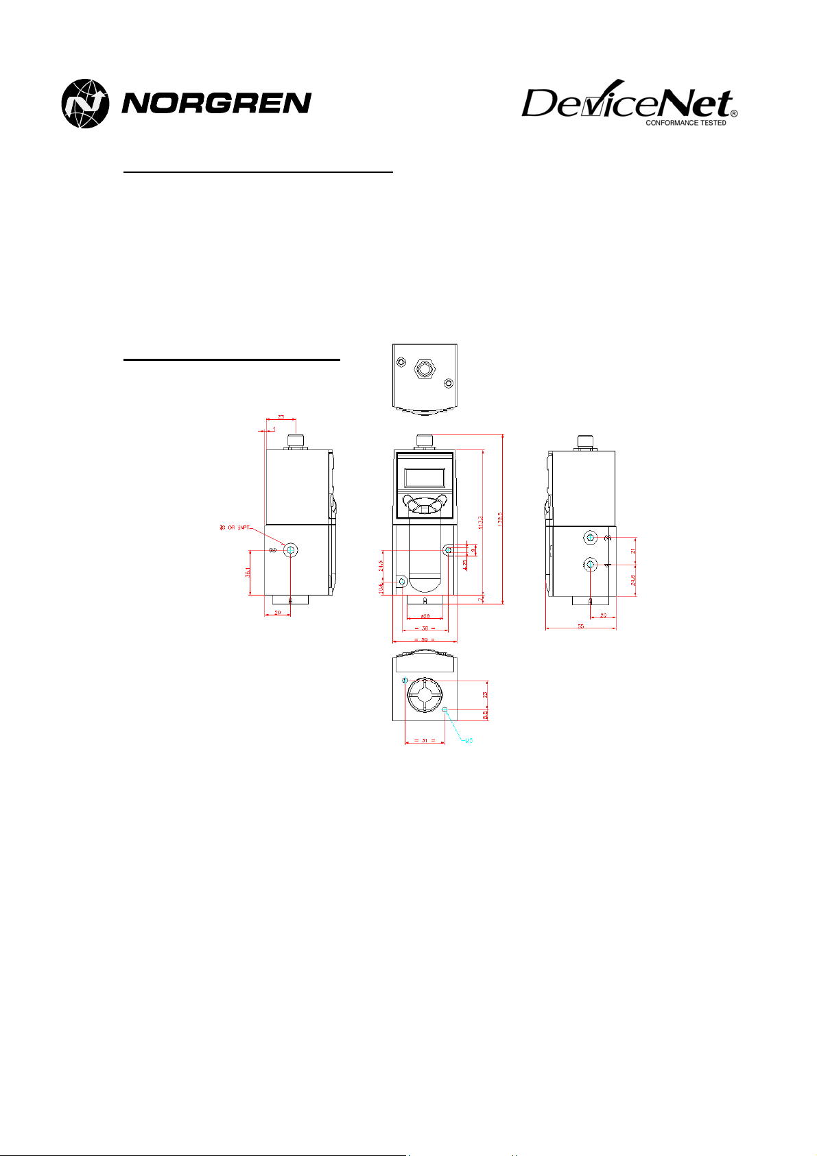
4. DIMENSION DETAILS
1=Inlet Port
2=Outlet Port
3=Exhaust Port
3
Page 4
5. INSTALLATION
Pneumatic Installation
• Supply Pressure: 15psig above maximum output required
(200psig max.)
• Output Pressure Range: 0-150psig
• Media: clean, dry 50µ filtered air
• Porting: G1/4; 1/4NPT; ISO2 Manifold Mount
•
Use oil-free air
•
Do not use PTFE tape
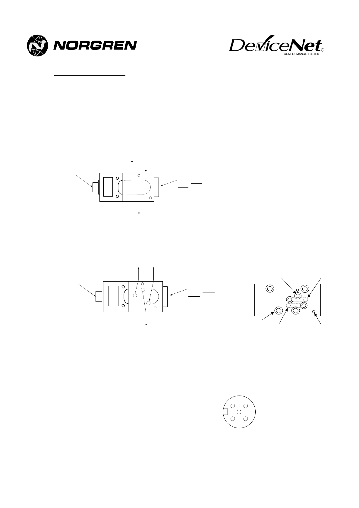
G1/4 & 1/4NPT variants
Electric al
connector
Exhaust port (3) Supply port
(1)
2
Output port (2)
1
Return spring
housing.
Do not
adjust.
3
• Connect pipe-work using 10mm OD, 8mm ID, plastic pipe, cut cleanly at right angles, with push-fit pipe
connections.
• Fit an exhaust silencer to Port 3 if required (this will only slightly degrade exhaust performance)
ISO2 Manifold Mount variant
Electrical
connector
Exhaust port (3
)
Supply port
Output port (2)
(1)
Return spring
Do not
housing.
adjust.
Output port (2)
ISO-2 sub base
mounting holes
Supply port (1)
Exhaust port (3)
VP51 mounting holes
(M4 tapped) x 2
• Use grub screws provided to plug cross drilled holes in interface plate
• Mount interface plate to ISO-2 sub base with four M6 screws, with gasket between plate and sub base.
• Place three O-rings in three counterbored holes in plate and mount VP51 with two M4 screws.
Electrical Installation
Connect the unit as follows using DeviceNet approved screened cable and a M12 female connector or with a
ready made M12 DeviceNet cable:
Pin 1: Drain (bare)
Pin 2: V+ (red)
Pin 3: V- (black)
Pin 4: CAN_H (white)
Pin 5: CAN_L (blue)
1
2
4
Connector pinout
5
looking onto the end of
the instrument
3
4
Page 5

DeviceNet Installation
• Download the DeviceNet VP51 EDS file from www.odva.org
• Register the EDS file using a DeviceNet configuration tool (e.g. Rockwell RSNetworx).
• The device MACID and baud rate are factory set to address 63 and Autobaud (see notes 1 & 2).
• Connect the DeviceNet VP51 to a DeviceNet network.
• Use the keypad or your DeviceNet configuration tool to change the MACID and baud rate parameters as
required.
• Map the polled i/o to a DeviceNet master device (e.g. PLC scanner).
• Control the pressure by polling the polled input ‘Demand Pressure’ over the range 0-4095 (=0-105% of
output pressure range).
• Use a DeviceNet configuration tool (e.g. Rockwell RSNetworx) to change the DeviceNet VP51 parameters
to suit the application (see note 3).
Notes:
1)
MACID -
can be changed either over the DeviceNet network or using the instrument’s keypad. If the DeviceNet
VP51 detects that another device on the network already has its MACID, it will display a “Set Node
Address” message instructing you to change the its MACID using the keypad. See section 7 of this
manual for more details.
2)
Baud rate -
the network, detects the baud rate and selects its own baud rate accordingly. In order for this to work, it
is necessary for the DeviceNet network to already have two or more other devices actively
communicating on the network. After successful Autobaud detection, the baud rate parameter
automatically switches to the selected baud rate. To run the Autobaud function again, the baud rate
setting must be changed back to Autobaud via the keypad or DeviceNet. If Autobaud detection is
unsuccessful or if the instrument has previously been set to an incorrect baud rate, it will automatically
display a “Set Baud Rate” message instructing you to change the baud rate using the keypad. See
section 7 of this manual for more details.
3)
ADR facility -
configured to provide this feature and a DeviceNet VP51 is replaced with a new one, the PLC will
automatically detect the new one and configure its address and parameters to be the same as the
device it is replacing. Refer to the PLC and DeviceNet configuration tool instructions for more details.
The DeviceNet VP51 MACID is factory set to 63. Once the DeviceNet VP51 is powered, this
The DeviceNet VP51 is factory set with Autobaud detection. This means that it ‘listens’ to
The DeviceNet VP51 supports ADR (Automatic Device Recovery). If the PLC has been
5
Page 6

6. DEVICENET INTERFACE DETAILS
I/O Data
Name I/O Type
Demand Pressure Polled Output 2 12 bit integer (0 to 4095)
Actual Pressure Polled Input 2 12 bit integer (0 to 4095)
Status Byte Polled Input 1 Bit 0: Set if difference between Demand
Notes
:
1) Inputs and Outputs are defined from the perspective of the DeviceNet network.
2) For 150 psi variant Demand Pressure value= 26 x (Required Pressure in psi), e.g. to output 100 psi, set
Demand Pressure value to 2600.
For 10 bar variant Demand Pressure value = 390 x (Required Pressure in bar), e.g. to output 6 bar, set
Demand Pressure value to 2340.
IMPORTANT - Only 12 of the 16 bits in the two Demand Pressure bytes are used. The four most
significant bits are ignored. Setting the Demand Pressure value above 4095 or below 0 may lead
to unpredicted output pressures.
3) If the polled input is read as a single value of 3 or more bytes, the two least significant bytes hold the
actual pressure and the third least significant is the status byte. For example, a returned value of
266044 (0x040F3C) represents an actual pressure of 0x0F3C = 3900 = 100% full scale and a status
byte of 0x04 = bit 2 set.
DeviceNet Parameters
The following parameters are available via a DeviceNet configuration tool (e.g. RSNetworx) or via DeviceNet
explicit messaging, using the class, instance, attribute and byte length details in the table. To use a DeviceNet
configuration tool, it is necessary to register the DeviceNet VP51 EDS file on the configuration tool. The EDS file
can be downloaded from
www.odva.org
Parameter
No.
1 Baud Rate Selectable from:
2 Serial
3 Demand
Name Format Default
number
Pressure
(see Note 1)
Autobaud, 125Kb/s, 250Kb/s,
500Kb/s (see note 1)
Read only 4 byte integer Factory
Read only integer, 0-4095
0 = minimum (zero) pressure
4095 = full scale output + 5%
span
(same as polled output, see
note 2)
No. Bytes Format
.
0 = minimum (zero) pressure
4095 = full scale output + 5% span
(see Note 2)
0 = minimum (zero) pressure
4095 = full scale output + 5% span
(see Note 3)
Pressure and Actual Pressure exceeds Error
Limit (see parameter 10).
Bit 1: Set if Bit 0 has been set for longer
than Error Delay (see parameter 11).
Bit 2: Set if Actual Pressure ≥ Threshold A
(see parameter 12).
Bit 3: Set if Actual Pressure ≥ Threshold B
(see parameter 13).
Bits 4-7: Not used.
(See Note 3)
Value
Autobaud 3 1 2 1
set
- 3 1 114
Class
Id
1 1 6 4
Instance
Id
Attribute
Id
(0x72)
Byte
length
2
6
Page 7

Parameter
No.
4 Actual
5 Status
6 Speed Selectable integer, 0-7
7 Prop Gain Selectable integer 0-7
8 Int Gain Selectable integer 0-7
9 Dither
10 Error Limit Selectable 0=105% (0-4095)
11 Error Delay Integer 0-999
12 Threshold A Selectable 0-105% (0-4095)
13 Threshold B Selectable 0-105% (0-4095)
14 Pressure
15 Signal
Name Format Default
Read only integer, 0-4095
Pressure
0 = minimum (zero) pressure
Value
- 4 13
Class
Id
4095 = full scale output + 5%
span
(same as polled input)
Byte
Read only byte (same as
polled input)
- 4 13(0x0D) 3 1
0 3 1 104
0 = fastest, 7 = slowest
See fig. 1
4 3 1 105
0 = low gain, 7 = high gain
(see note 3) See fig. 3
4 3 1 106
0 = low gain, 7 = high gain
(see note 3) See fig. 3
Amplitude
Selectable integer 0-7
0 = no dither, 7 = maximum
4 3 1 107
dither
0 = Error Limit Off
10%
(390)
3 1 109
105% = Full scale output + 5%
Set in 100ths of a second
0 = Status Bit 2 always set
200
(2 secs)
50%
(1950)
3 1 110
3 1 111
105% = Full scale output + 5%
0 = Status Bit 3 always set
100%
(3900)
3 1 112
105% = Full scale output + 5%
Units
Selectable from:
Bar, psi, kPA, Atm, kg/cm^2
Sets units for pressure display
Depends
on part
number
3 1 108
on LCD
Failure
Mode
Selectable from Fail Safe, Fail
Freeze
Sets operation of device on
Fail Safe 3 1 113
loss of polled signal from
network (see note 2).
Instance
Id
(0x0D)
Attribute
Id
3 2
(0x68)
(0x69)
(0x6A)
(0x6B)
(0x6D)
(0x6E)
(0x6F)
(0x70)
(0x6C)
(0x71)
Notes:
1) If the baud rate parameter is set to Autobaud the Device will automatically listen to the network and
work out the correct baud rate. The baud rate parameter will then automatically be set to the
appropriate baud rate and will remain at its new setting even after removing power from the Device. In
order to run the Autobaud function again, the baud rate must be changed back to Autobaud via
DeviceNet or via the keypad.
2) Demand Pressure can only be set by means of a polled I/O message. It can be read but not set by
explicit messaging. If no polled message is received, the output pressure is set according to parameter
15 – Signal Failure Mode. If Fail Safe is selected, the output pressure will be zero when no polled
messages are being received. If Fail Freeze is selected, the output pressure will remain at its last set
value when no polled messages are being received.
3) To set the
proportional gain
best possible response time without causing unacceptable overshoot or oscillations.
Once proportional gain is set correctly, increase
without causing unacceptable hunting (slow oscillations) on the output. See figs 2 & 3.
, first set the integral gain to 0, then adjust the proportional gain to give the
integral gain
to achieve the best possible accuracy
Byte
length
1
1
1
1
1
2
1
1
1
1
7
Page 8

1
Fig. 1 - Speed Setting Effects
at default Proportional and Integral Gain
12
10
8
6
Pressure, bar
4
2
0
Time
Fig. 2 - Proportional Gain Effects
at default Integral Gain and Speed
12
10
8
6
Pressure, bar
4
2
0
Time
Fig. 3 - Integral Gain Effects
10.2
10.1
at default Proportional Gain and Speed
10.0
Pressure, bar
9.9
9.8
Time
8
Page 9

x
x
x
7. LOCAL USER INTERFACE DETAILS
The DeviceNet VP51 includes an integral keypad and LCD display. During normal operation, this will display the
current output pressure of the instrument and its DeviceNet MACID (node address number). The keypad can be
used to locally set the device MACID and baud rate. The complete menu structure is shown in fig. 4.
Device goes
online
correctly
xxx . psi
Node xx
OK
Password
****
C
C
OK
C
Set-up
Comms
DN
UP
Change
Password
DN
Help
www.norgren.
com
UP
OK
Set Baud
Autobaud
OK
Set Node
x
OK
C
Reset :
Cycle Pow..
New
C
****
OK OK
C
Confirm
****
OK
Incorrect
baud rate or
Autobaud
fails
Duplicate
node address
detected
Figure 4 – Local User Interface Menu Structure
Set Baud
Rate
Set Node
Address
OK
Password
****
OK
Password
****
OK
OK
Set Baud
xx
OK
Set Node
x
OK
Reset :
Cycle Pow..
9
Page 10

Changing MACID or Baud Rate
From Normal Operating Mode
When the Device is in normal operating mode (i.e. communicating on DeviceNet), the baud rate or MACID can
be changed by following the steps detailed below:
• Press
• Enter the password using the numbered arrow keys (see section on Password below).
• Press
• Use the up and
to skip this stage or cancel changes to the baud rate.
• Use the
Alternatively, press C to skip this stage or cancel changes to the MACID.
• If either the baud rate or the MACID have been changed, a message will be displayed reading Reset: Cycle
Power to Activate – Cancel to Abort. In order for the new settings to become active, the DeviceNet VP51
must be reset. This should be done either by disconnecting and reconnecting the device, or cycling the
network power. Alternatively, press C to return to the previous settings.
From Baud Rate Fault Condition
If the baud rate is incorrect or the Autobaud routine has not succeeded, the DeviceNet VP51 display will
automatically switch to display the message Set Baud Rate. Under these circumstances, following the steps
below:
• Press OK to enter the user interface.
• Enter the password using the numbered arrow keys (see section on Password below).
• Use the up and
• Use the
• The message will be displayed reading Reset: Cycle Power to Activate. In order for the new settings to
become active, the DeviceNet VP51 must be reset. This should be done either by disconnecting and
reconnecting the device, or cycling the network power.
From Node Address fault condition
If the DeviceNet VP51 detects that another device on the network already has its MACID (node address), it will
automatically switch to Set Node Address. Under these circumstances, following the steps below:
• Press OK to enter the user interface.
• Enter the password using the numbered arrow keys (see section on Password below).
• Use the
• The message will be displayed reading Reset: Cycle Power to Activate. In order for the new settings to
become active, the DeviceNet VP51 must be reset. This should be done either by disconnecting and
reconnecting the device, or cycling the network power.
from the default screen to enter the user interface.
OK
to enter the Set-up Comms menu.
OK
arrows to select the required baud rate and press
down
up
up
up
and
and
and
arrows to select the required MACID (node address) and press OK to accept.
down
arrows to select the network baud rate and press
down
arrows to change the MACID (node address) if required, and press
down
arrows to change the MACID (node address) and press
down
to accept. Alternatively, press
OK
to accept.
OK
to accept.
OK
to accept.
OK
User Interface Password
Entry into the local user interface is password controlled to prevent unauthorised access. All standard DeviceNet
VP51s are shipped with the password disabled. In this case, press OK from the password screen to enter the
user interface.
To change the Password, enter the user interface and use the up and down arrows to select the Change
Password menu. Press OK then enter and confirm the new password – the password can be any combination
of up to four digits in the range 1 to 4, entered using the numbered arrow keys.
In case the password is forgotten, there is an override facility – from the password screen, press and hold down
then press and hold down OK, whilst keeping C held down. Hold down both until the user interface is entered
C
(approx. 5 secs).
C
10
Page 11

8. EC DECLARATION OF CONFORMITY
The DeviceNet VP51 Digital Proportional Valve complies with the EC Pressure Equipment Directive and the
generic EMC standards.
BS EN 61000-6-4: 2001 Electromagnetic Compatibility
Part 6-4 Generic Standard
Emission standard for industrial environments
BS EN 61000-6-2: 1999 Electromagnetic Compatibility
Part 6-2 Generic Standards –
Immunity for industrial environm
ents
9. ODVA DECLARATION OF CONFORMITY
11
 Loading...