

Page 1
Suitable for all cylinder ranges with
BU
BN
+
~
BK
1
~
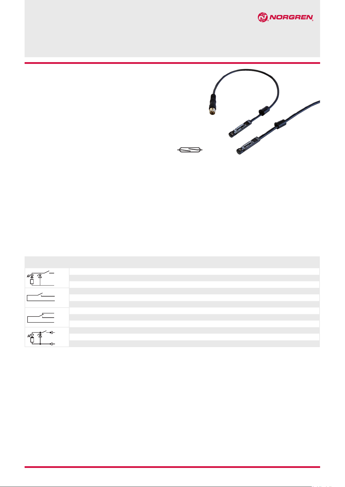
magnetic piston
Switches can be mounted flush with the
delivered special adaptor
LED indicator on LSU models
Alternative variants allows a wide range of
application
Technical features
Operation:
M/50/LSU Normally open
with LED (yellow)
Switching voltage (Ub):
10 ... 240 V a.c./170 V d.c.
Switching voltage output:
Ub - 2,7 V
Switching current (see graph
overleaf):
0,18 A max.
Switching power:
10 W/10 VA max.
Contact resistance:
150 mΩ
Response time:
1,8 ms
Operating temperature:
-25°C ... +80°C,
High temperature version:
+150°C max.
Protection rating (EN 60529):
IP 66
Shock resistance:
50 g (during 11 ms)
M/50/LSU, M/50/RAC, TM/50/RAU
Magnetically operated switches
Vibration resistance:
35 g (at 2000 Hz)
Cable type:
2 x 0,25: PVC, PUR or silikone
3 x 0,25 PVC
Cable length:
2, 5 or 10 m
Electromagnetic compatibility
according to:
EN 60947-5-2
Reed switches
Materials:
Body: plastic
Cable: see table below
Technical data, standard models
Symbol Voltage
4
* Insert cable length
*1) Plug-in connector see page 2
Color code: BK = black, BN = brown, BU = blue
(V a.c.) (V d.c.)
10 ... 240 10 ... 170 180 Closer -25 ... +80 • IP66 — 2, 5 or 10 PVC 2 x 0,25 37 M/50/LSU/*V
~
10 ... 240 10 ... 170 180 Closer -25 ... +80 • IP66 — 5 PUR 2 x 0,25 37 M/50/LSU/5U
10 ... 240 10 ... 170 180 Closer -25 ... +150 — IP66 — 2 Silicon 2 x 0,25 37 TM/50/RAU/2S
BN
BU
10 ... 240 10 ... 170 180 Changeover -25 ... +80 — IP66 — 5 PVC 3 x 0,25 37 M/50/RAC/5V
BK
BU
BN
10 ... 60 10 ... 60 180 Closer -25 ... +80 • IP66 Plug M8 x 1 0,3 PVC 3 x 0,25 16 M/50/LSU/CP *1)
+
BN
~
Current
max. (mA)
unction Temperature
F
(°C)
LED Protection
class
Features Cable length
(m)
Cable
type
Weight
(g)
Model
10/14 1999-4000d
Our policy is one of continued research and development. We therefore reserve the right to amend,
without notice, the specifications given in this document. © 2014 Norgren GmbH
N/en 4.3.005.01
Page 2
M/50/LSU, M/50/RAC, TM/50/RAU
Options selector
Variants
High temperature (+150°C)
Type
Reed with LED
Reed without LED
Switching voltage
Standard
Special
Function
Closer
Changeover
Substitute
T
Substitute
L
R
Substitute
S
A
Substitute
U
C
Switching current and switching voltage
M/50/LSU, M/50/RAC, M/50/RAU
mA
200
150
100
10 W
10 VA
˙M/50/˙˙˙/˙˙˙
Accessories
Plug-in connector cable with nut
Outer cover Cable length Weight (kg) Connector Model
PVC 3 x 0,25 5 m 0,18 M8 x 1 M/P73001/5
PUR 3 x 0,25 5 m 0,18 M8 x 1 M/P73002/5
Cable Substitute
Silicone
PVC
PUR
Cable length/plug
2 m
5 m
10 m
Cable (0,3 m) with plug M8 x 1
Substitute
S
V
U
2
5
10
CP
50
a.c./d.c.
0
0
50
100
150 200
230
V
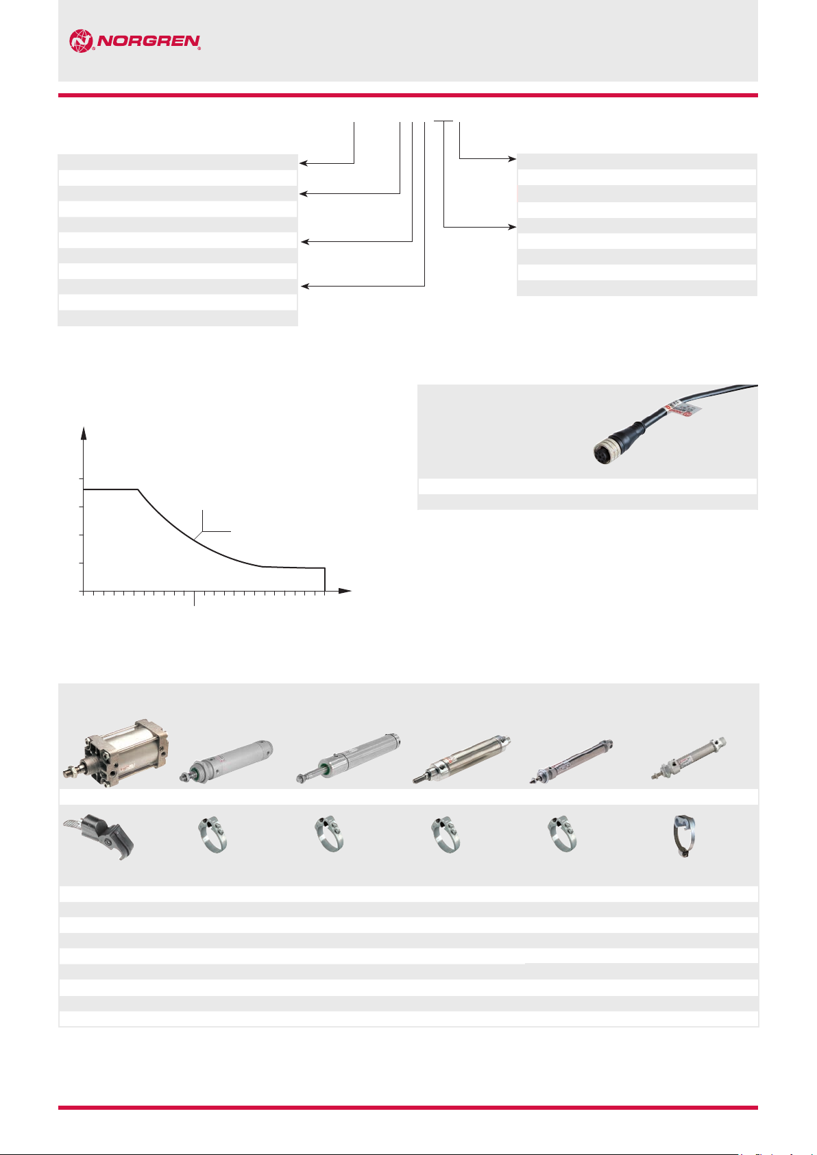
Mounting elements for magnetic switches
Cylinder with external tie rods
RA/8000/M, KA/8000/M
RA/28000/M, RM/900/M
Mounting elements
Cylinder
Ø(mm) Model
32 ... 200 QM/27/2/1 32 QM/33/432/22 32 QM/33/432/22 10 QM/33/010/22 10 QM/33/010/22 10 QM/33/010/23
Dimensions see relevant cylinder sheets.
Roundline cylinder
RM/55401/M
Cylinder
Ø(mm) Model
40 QM/33/440/22 40 QM/33/440/22 12 QM/33/012/22 12 QM/33/012/22 12 QM/33/016/23
50 QM/33/450/22 50 QM/33/450/22 16 QM/33/016/22 16 QM/33/016/22 16 QM/33/016/23
63 QM/33/463/22 63 QM/33/463/22 20 QM/33/020/22 20 QM/33/020/22 20 QM/33/020/23
80 QM/33/480/22 80 QM/33/080/22 25 QM/33/025/22 25 QM/33/025/22 25 QM/33/025/23
100 QM/33/410/22 100 QM/33/100/22 32 QM/33/032/22
Roundline cylinder
KM/55001/M, VSM/55640/N2
Cylinder
Ø(mm) Model
125 QM/33/125/22 40 QM/33/040/22
Roundline cylinder
R./57100/M, R./57200/M
R./57300/M
Cylinder
Ø(mm) Model
50 QM/33/050/22
63 QM/33/063/22
Roundline cylinder
< 25 mm stroke
RM/8000/M, KM/8000/M
RM/28000/M
Cylinder
Ø(mm) Model
Roundline cylinder
> 25 mm stroke
RM/8000/M, KM/8000/M
RM/28000/M
Cylinder
Ø(mm) Model
N/en 4.3.005.02
Our policy is one of continued research and development. We therefore reserve the right to amend,
without notice, the specifications given in this document. © 2014 Norgren GmbH
1999-4000d 10/14
Page 3

Dimensions
M/50/LSU/*V, M/50/LSU/5U, TM/50/RAU/2S
Cable length L = 2, 5 or 10 m
M/50/LSU, M/50/RAC, TM/50/RAU
A-B
5,1
ø 6,4
M/50/RAC/5V
Cable length L = 5 m
A-B
5,1
ø 6,4
M/50/LSU/CP
A-B
5,1
ø 6,4
+30
L
1
30
A
+10
50
1
Fixing screw
2
+ BN = brown
- BU = blue
(output)
1,5
1
30
B
+30
L
A
2
+10
50
1
Fixing screw
2
- BK = black
+ BN = brown
- ≠BU = blue
1,5
1
30
1,5
B
±15
300
A
B
2
31,5 ... 36
X
4 BK
1
Fixing screw
3
Plug M8x1
Color code
X
3
1 BN
3 BU
BK = black
BN = brown
BU = blue
Warning
These products are intended for use in industrial control systems only.
Do not use these products where values can exceed those listed under
‘Technical Features/Data’.
Before using these products for non-industrial applications, lifesupport systems, or other applications not within published
specifications, consult NORGREN.
Through misuse, age, or malfunction, components used in control
systems can fail in various modes.
The system designer is warned to consider the failure modes of all
10/14 1999-4000d
Our policy is one of continued research and development. We therefore reserve the right to amend,
without notice, the specifications given in this document. © 2014 Norgren GmbH
component parts used in control systems and to provide adequate
safeguards to prevent personal injury or damage to equipment in the
event of such failure.
System designers must provide a warning to end users in the system
instructional manual if protection against a failure mode cannot be
adequately provided.
System designers and end users are cautioned to review specific
warnings found in instruction sheets packed and shipped with these
products.
N/en 4.3.005.03
 Loading...