

Page 1
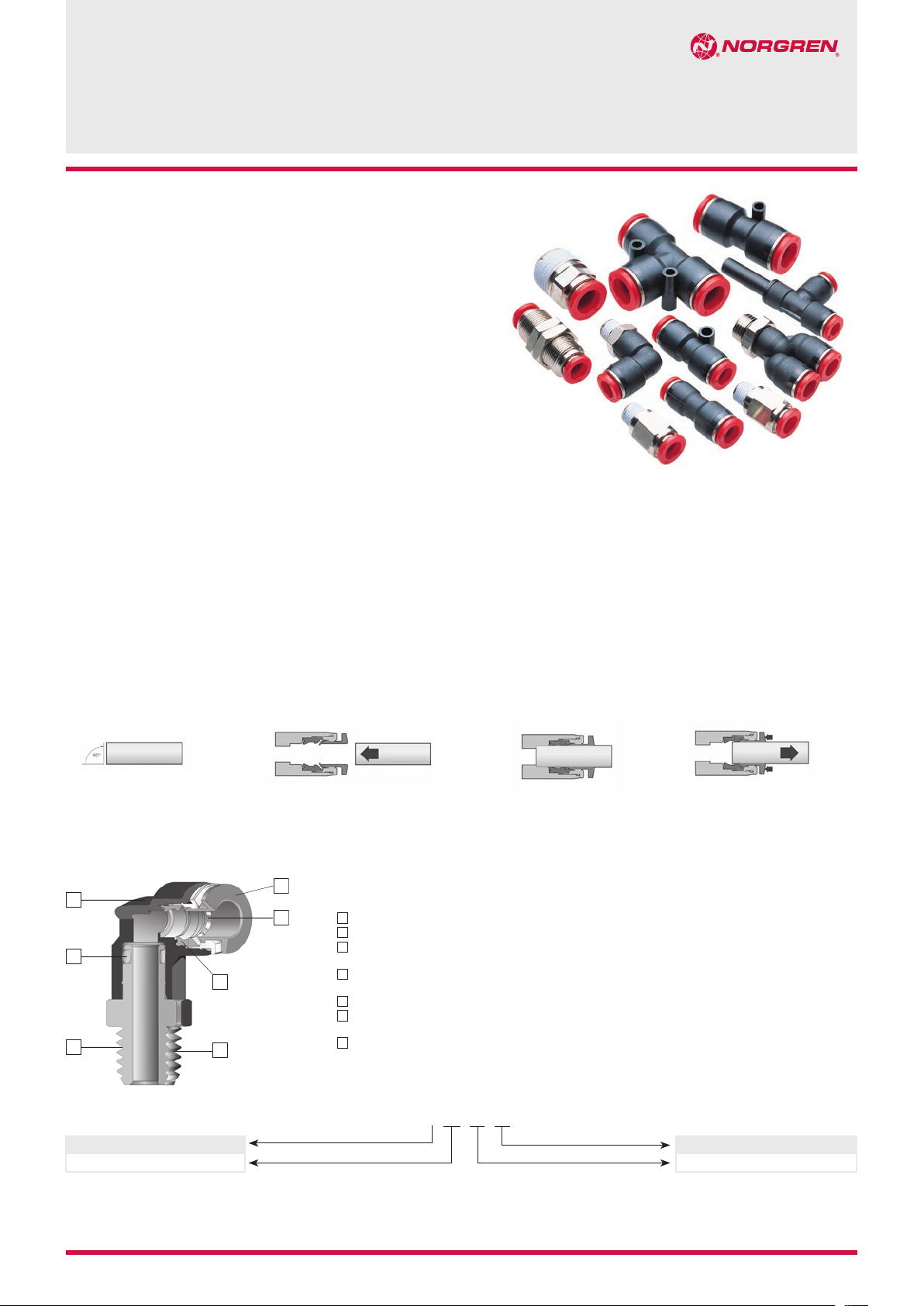
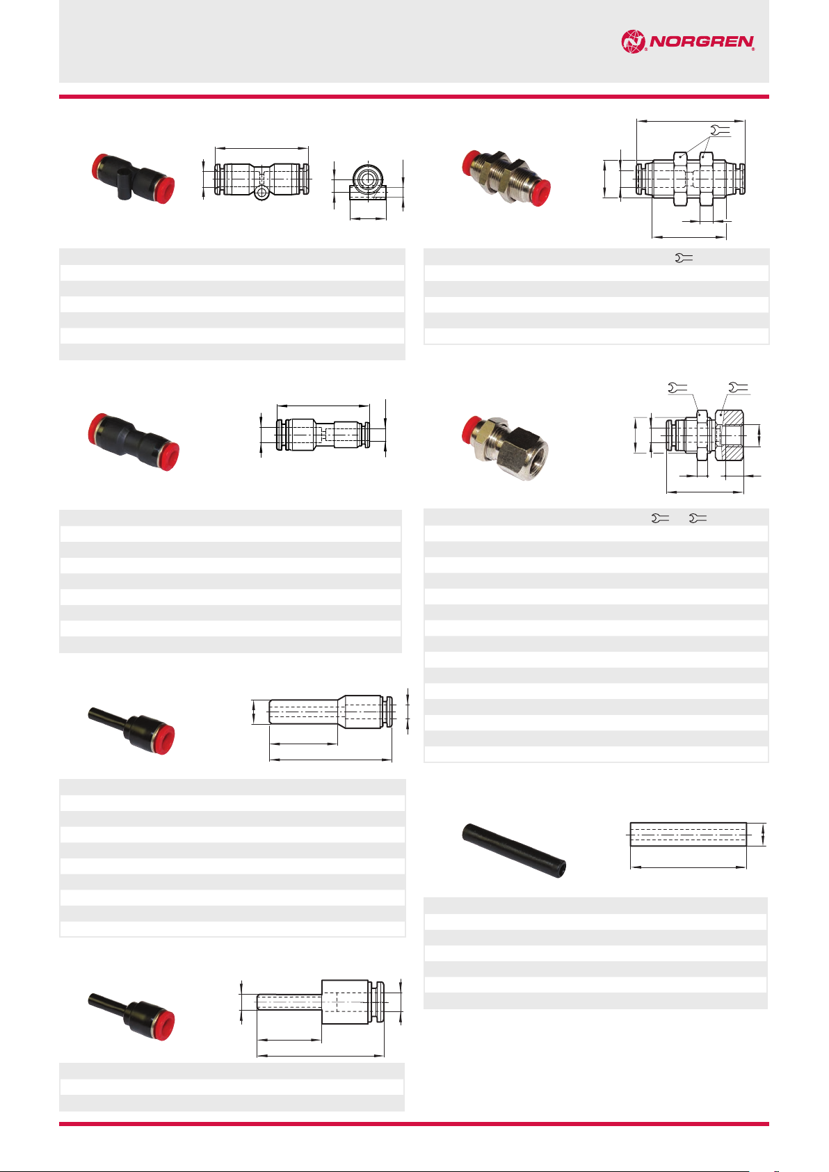
Norgren Pneufit® C fittings are ready to use,
offering fast assembly with no need for tools
providing optimum flow.
Pneufit
®
C offers a broad range of over 1,000
composite push-in pneumatic fittings to complement
our established all brass Pneufit® series.
Releasable stainless-steel grab-ring to grip
PA or PUR tube (85 or 95 durometer).
Nickel plated brass components provide corrosion
and contamination resistance and an extended life.
Pre applied thread sealant on all taper threads and
recessed captive O-ring on parallel threads provides
optimum rapid sealing.
Technical features
Medium:
Compressed air
Operating pressure:
10 bar max.
Vacuum:
750 mmHg
Tube sizes:
4, 6, 8, 10, 12 und 16 mm
Method of assembly
Thread sizes:
M5, M6, 1/8, 1/4, 3/8 and 1/2
ISO G, ISO Rc and ISO R
Tubing types:
PA 11 or 12
PUR 85, 95 or 98 durometer
Operating temperature:
-20°C ... +60°C
PUSH-IN fittings, metric
Warning:
The Norgren Pneufit® C range
must not be used in vehicle air
braking or ancillary systems. For
push in fittings suitable for these
applications, please refer to the
Fleetfit range.
Pneufit® C
Ø 4 ... 16 mm O/D tube
Materials
Body: PBT
Seals: NBR (silicone free)
u-packing and O-rings
Threaded bodies: nickel plated
brass
Release sleeve and backing ring:
POM
Grab-ring: stainless steel
Collar: nickel plated brass
Thread sealant: chemitech G175L
1. Ensure that the end of the
tube is cut square and is free
from burrs.
1
5
6
Option selector
Thread type
Shape
2. Push the tube through
the collet into the fitting.
2
3
4
7
1
Impact resistant PBT body in black
2
Release buttons are red for metric, grey for inch
3
Stainless steel grab ring with special design to retain
softer tube and provide easy releasability.
4
Silicon free U-packing provides leak tight tube seal
under side loading.
5
Stem seal provides leak tight 360° swivel connection.
6
Nickel plated brass threads and notches on hex to
signify NPT.
7
Pre-applied thread sealant on tapered threads and
recessed captive O-ring on parallel threads.
3. Continue pushing the tube
through the ‘O’-ring until it
bottoms on the tube stop then
pull back.
4. To disconnect push the tube
into the fitting, hold down the
collet and withdraw the tube.
C0 ˙˙˙˙˙˙˙
Thread size/tube size
Thread size/tube size
3/14 2006-9005e
Our policy is one of continued research and development. We therefore reserve the right to amend,
without notice, the specifications given in this document. © 2014 Norgren Ltd
N/en 9.1.020.01
Page 2

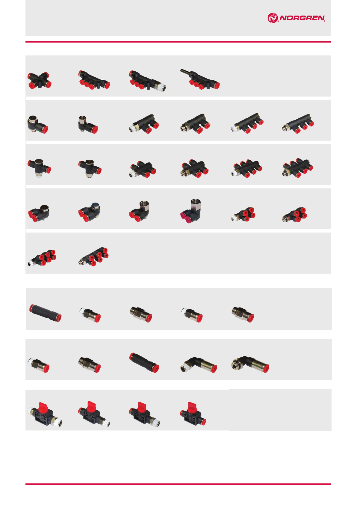
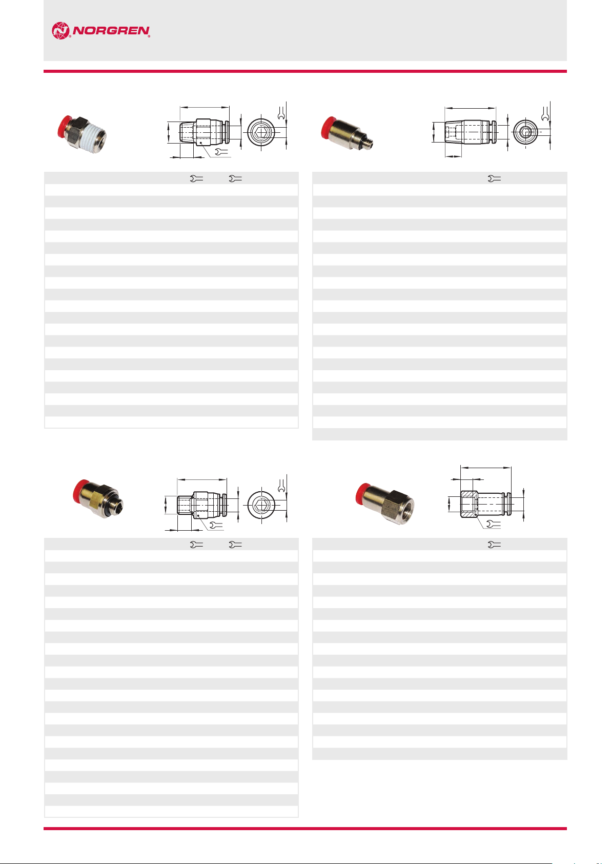
Pneufit® C
Straight adaptors and connectors
Straight adaptor, BSPT thread
(external + internal hex)
C0125
Straight adaptor, BSPP thread
(external + internal hex)
C0225
Straight adaptor, metric or
BSPT thread
(internal hex only)
C012A/C022A
Female adaptor, metric or
BSPP thread
C0226
Straight union
C0020
Straight union (unequal)
C0020
Page 6
Stem reducer
C0023
Page 7
Plug
C0004
Page 8
Page 6
Stem expander
(stem/tube)
C0023
Page 7
Cap
(female plug)
C0012
Page 8
Elbow adaptors and connectors
Union elbow
C0040
Page 8
90° Swivel elbow adaptor,
BSPT thread
C0147
Page 8
Y and quadruple connectors
Union Y
(equal + unequal)
C0082
Swivel Y adaptor,
BSPT thread
C0188
Swivel Y adaptor,
BSPP thread
C0288
Page 6
Bulkhead union
C0029
Page 7
90° Swivel elbow adaptor,
BSPP thread
C0247
Page 8
Stem Y
(equal + unequal)
C0084
Stem elbow
C0043
Page 9
Page 6
Straight adaptor, BSPP thread
(female bulkhead)
C0232
Page 7
90° Swivel elbow adaptor
(extended), metric or
BSPT thread
CO154/CO254
Page 9
Quadruple stem
reducer
C0096
Quadruple Y union,
BSPT thread
C0195
Page 7
Stem union
(equal)
C0022
Page 7
90° Swivel elbow adaptor
(female), metric or
BSPT thread
C0148/C0248
Page 9
Page 7
Stem union
(unequal)
C0022
Page 8
Quadruple Y union,
BSPP thread
C0295
Bulkhead union elbow
C0049
Page 9
Quadruple reducer
C0097
Page 10
Page 10
Tee connectors and adaptors
Union tee
(equal)
C0060
Page 11
Stem tee
(unequal)
C0063
Page 12
Union tee
(unequal)
C006A
Page 11
Stem side tee
(equal)
C0064
Page 13
Banjo flow controler
Banjo flow control (out),
BSPT thread
A0
C0T
Page 19
Swivel speed control (out),
BSPT thread
T56
CO
Banjo flow control (out),
metric or BSPP thread
COK51
Page 19
Swivel speed control (out),
metric or BSPP thread
COK56
Page 10
Page 10
Swivel tee adaptor,
BSPT thread
C0167
Page 12
Stem side tee
(unequal)
C0064
Page 13
w control
Banjo flo
(in), BSPT thread
COSAO
Page 20
Speed control and pilot check,
metric or BSPT thread CO1GN
Page 11
Swivel tee adaptor,
BSPP thread
C0267
Page 12
Swivel side tee adaptor,
BSPT thread C0168
Page 13
Banjo flow control (in),
metric or BSPP thread
COL51
Page 20
ontrol and pilot check,
Speed c
metric or BSPT thread CO2GN
Page 11
Page 11
Swivel side tee adaptor
(female), metric or
BSPT thread C016C/C026C
Page 12
Swivel side tee adaptor,
BSPP thread C0268
Page 13
Shrouded banjo (out),
BSPT thread
TBO
CO
Page 20
In-line flow control
COOGE
Page 11
Stem tee
(equal)
C0063
Page 12
Shrouded banjo (out), metric
or BSPP thread
COKBO
Page 20
In-line flow control
C00GP
Page 21
N/en 9.1.020.02
Page 21
Our policy is one of continued research and development. We therefore reserve the right to amend,
Page 22
without notice, the specifications given in this document. © 2014 Norgren Ltd
Page 22
Page 23
Page 23
2006-9005e 3/14
Page 3
Cross and manifolds
Union cross
C0090
Manifold union
C00D3
Male manifold, BSPT thread
C01D3
Pneufit® C
Stem manifold
C00J3
Page 13
Banjo, metric or BSPP thread
C0A51
Page 14
Single universal tee,
BSPT thread
C0N71
Page 16
Branch adaptor,
BSPT thread
CON70
Page 17
Triple branch adaptor,
BSPT thread
COH70
Page 19
Page 14
Banjo (with top port), metric or
BSPT thread
COD51, COE51, COF51, COG51
Page 14
Single universal tee,
BSPP thread
C0A71
Page 16
Branch adaptor, metric or
BSPP thread
COA70
Page 17
riple branch adaptor,
T
BSPP thread
C0C70
Page19
Page 14
2x Swivel elbow adaptor,
BSPT thread
C0Q51
Page 15
Double universal tee,
BSPT thread
COQ71
Page 16
Female branch adaptor,
BSPT thread
C0*7K
Page 18
Page 14
2x Swivel elbow adaptor,
BSPP thread
C0B51
Page 15
Double universal tee,
BSPP thread
C0B71
Page 16
Female branch adaptor, metric
or BSPP thread
C0*7J
Page 18
3x Swivel elbow adaptor,
BSPT thread
COH51
Page 15
Triple universal tee,
BSPT thread
C0H71
Page 17
e branch adaptor,
Doubl
BSPT thread
C0Q70
Page 18
3x Swivel elbow adaptor,
BSPP thread
C0C51
Page 15
Triple universal tee,
BSPP thread
COC71
Page 17
Double branch adaptor,
BSPP thread
C0B70
Page 18
In-line non-return valve
In-line non-return valve
C00GL
Page 24
In-line non-return valve (in),
BSPT thread
C01G2
Page 24
Self sealing adaptors
Straight adaptor,
BSPT thread
C0124
Page 25
Straight adaptor,
BSPP thread
C0224
Page 25
Hand valves
3/2 Shut-off valves,
BSPT thread CO1GG
Page 26
3/2 Shut-off valves,
BSPT thread CO1GH
Page 26
In-line non-return valve (in),
metric or BSPP thread
C02G2
Page 24
Straight union
C002J
Page 25
3/2 Shut-off v
BSPT thread CO1GJ
Page 26
alves,
In-line non-r
BSPT thread
C01G3
Page 24
Swivel elbow,
BSPT thread
CO14J
Page 25
3/2 Shut-off valves
CO1GF
Page 26
eturn valve (out),
In-line non-return valve (out),
metric or BSPP thread
C02G3
Page 24
Swivel elbow,
BSPP thread
C024J
Page 25
3/14 2006-9005e N/en 9.1.020.03
Our policy is one of continued research and development. We therefore reserve the right to amend,
without notice, the specifications given in this document. © 2014 Norgren Ltd
Page 4
Pneufit® C
1000
0
1
2
345 6
789 10
700
500
300
100
0
1
2
3456
789 10
250
350
150
0
1
2
3456
789 10
250
200
150
100
0
1
2
345 6
789 10
140
100
0
1
2
3456
789 10
2000
1500
1000
1400
1000
1000
800
600
400
200
3
5
6
400
300
200
100
160
120
876543210
8
76
5432
1
150
100
0
300
400
500
200
100
8
76
1
1000
1400
1000
1500
2000
100
125
8
76
1
300
400
500
200
100
8
76
5432
1
0
1000
8
76
5
32
1
600
800
400
200
8
76
5432
1
0
1000
8
76
5432
1
0
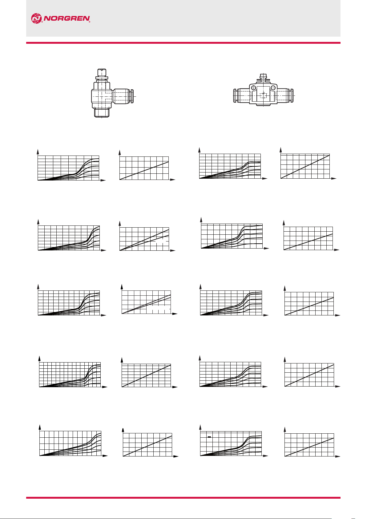
Speed controllers flowrate for C0K51, C0TA0,
C0L51, C0K56, C0T56 and C0SA0 banjo types
3, 4 and 6 mm
M5
Control flow Free flow
8
7
Needle turn
5
3
50
Pressure (bar)
Flow rate (l/m)
1
80
40
Flow rate (l/m)
4, 6 and 8 mm
1/8
Control flow Free flow
8
7
5
3
Pressure (bar)
Flow rate (l/m)
1 234 5678910
0
Needle turn Pressure (bar)
Flow rate (l/m)
1
0
Pressure (bar)
04-01
5432
Speed controllers flowrate for C00GE, C00GP
C00G*0400
Control flow Free flow
8
7
75
5
60
Flow rate (l/m)
20
Needle turn Pressure (bar)
3
1
Pressure (bar)
50
25
Flow rate (l/m)
0
C00G*0600
Control flow Free flow
8
7
5
50
Flow rate (l/m)
Needle turn Pressure (bar)
3
1
Pressure (bar)
Flow rate (l/m)
5432
4, 6, 8, 10 and 12 mm
1/4
Control flow Free flow
Flow rate (l/m)
1
2
0
7
4
8 9101112
Needle turn Pressure (bar)
6, 8, 10 and 12 mm
3/8
Control flow Free flow
800
Flow rate (l/m)
600
3
1
0
7
9111315
5
Needle turn Pressure (bar)
8, 10 and 12 mm1/2
Control flow Free flow
500
Flow rate (l/m)
3
1
0
7
5
8
7
800
600
5
400
3
200
1
1
Pressure (bar)
Flow rate (l/m)
0
1
8
7
5
3
600
Pressure (bar)
Flow rate (l/m)
1
200
0
1
8
7
5
3
1
500
Pressure (bar)
91113
Needle turn Pressure (bar)
Flow rate (l/m)
0
1
06-02, 04-02
5432
76
5432
76
5432
8
8
76
8
C00G*0800
Control flow Free flow
50
Flow rate (l/m)
C00G*1000
Control flow Free flow
Flow rate (l/m)
C00G*1200
Control flow Free flow
600
200
Flow rate (l/m)
8
7
800
5
600
3
400
1
200
Pressure (bar)
Flow rate (l/m)
Pressure (bar)
Pressure (bar)
Flow rate (l/m)
750
500
250
Flow rate (l/m)
0
Needle turn Pressure (bar)
8
7
5
3
1
Needle turn Pressure (bar)
8
7
5
3
1
Needle turn Pressure (bar)
4
N/en 9.1.020.04
Our policy is one of continued research and development. We therefore reserve the right to amend,
without notice, the specifications given in this document. © 2014 Norgren Ltd
2006-9005e 3/14
Page 5
0
100
200
300
400
1
2
3456
789 10
300
400
500
200
100
8
76
5432
1
0
0
1
2
3456
789 10
100
200
300
400
300
400
500
200
100
8
76
5432
1
0
200
400
600
800
0
1
2
3456
789 10
300
400
500
200
100
8
76
5432
1
0
1000
1
300
400
500
200
100
8
76
5432
1
0
Speed controllers flowrate for C01GN and C02GN banjo types
Pneufit® C
6 and 8 mm
1/8
Control flow Free flow
Flow rate (l/m)
0
6 and 8 mm
1/4
Control flow Free flow
Flow rate (l/m)
0
5
3
1
Pressure (bar)
Flow rate (l/m)
0
Needle turn Pressure (bar)
5
3
1
Pressure (bar)
Flow rate (l/m)
0
Needle turn Pressure (bar)
T
8, 10 and 12 mm
3/8
Control flow Free flow
Flow rate (l/m)
0
10 and 12 mm
1/2
Control flow Free flow
800
600
400
200
Flow rate (l/m)
0
2
3456
0
5
3
1
Pressure (bar)
Flow rate (l/m)
0
Needle turn Pressure (bar)
5
3
1
Pressure (bar)
Flow rate (l/m)
789 1110
Needle turn Pressure (bar)
0
ø X
ø A
ø K
Technical data
Ø A Ø K T*1) Ø X
4 10,5 15 9,5
6 12,5 16,5 12
8 14,5 18,5 14
10 17,5 20 16,5
12 20,5 23 19
16 27 23,5 25
*1) Dimensions here and in the individual tables refer to the collet being in the
‘IN’ position.
3/14 2006-9005e N/en 9.1.020.05
Our policy is one of continued research and development. We therefore reserve the right to amend,
without notice, the specifications given in this document. © 2014 Norgren Ltd
Thread Recommended torque Thread Recommended torque
M5 1,5 Nm
M6 2,3 Nm
G1/8 10 Nm R1/8 7 Nm
G1/4 15 Nm R1/4 12 Nm
G3/8 25 Nm R3/8 22 Nm
G1/2 40 Nm R1/2 28 Nm
Page 6
Pneufit® C
C
B
Straight adaptor (external + internal hex)
C0125
B
Ø A B C G
4 R1/8 21,5 8 10 3 C01250418
4 R1/4 20,5 10 14 3 C01250428
4 R3/8 22 11 17 3 C01250438
6 R1/8 22 8 12 4 C01250618
6 R1/4 21 10 14 5 C01250628
6 R3/8 22 11 17 5 C01250638
6 R1/2 29,5 14 19 5 C01250648
8 R1/8 27,5 8 14 5 C01250818
8 R1/4 25,5 10 14 6 C01250828
8 R3/8 23 11 17 6 C01250838
8 R1/2 29,5 14 19 6 C01250848
10 R1/8 28,5 8 17 5 C01251018
10 R1/4 30,5 10 17 6 C01251028
10 R3/8 24,5 11 17 8 C01251038
10 R1/2 29,5 14 19 8 C01251048
12 R1/8 31,5 8 19 5 C01251218
12 R1/4 33 10 19 6 C01251228
12 R3/8 30 11 19 8 C01251238
12 R1/2 30 14 19 8 C01251248
16 R3/8 37,5 11 24 10 C01251638
16 R1/2 40,5 14 24 10 C01251648
C
ø A
G
Model
1
Straight adaptor (internal hex only)
C012A, C022A
1
Ø A B C G
4 M5 22 4,5 2 C022A0405
4 M6 22 4 3 C022A0406
4 R1/8 20,5 8 3 C012A0418
4 R1/4 20,5 10 3 C012A0428
4 R3/8 20,5 11 3 C012A0438
6 M5 22,5 5 2 C022A0605
6 M6 22,5 4 3 C022A0606
6 R1/8 22 8 4 C012A0618
6 R1/4 22,5 10 4 C012A0628
6 R3/8 22,5 11 4 C012A0638
8 R1/8 27 8 5 C012A0818
8 R1/4 25 10 6 C012A0828
8 R3/8 25 11 6 C012A0838
8 R1/2 25 14 6 C012A0848
10 R1/8 28 8 5 C012A1018
10 R1/4 29 10 6 C012A1028
10 R3/8 29 11 8 C012A1038
10 R1/2 29 14 8 C012A1048
12 R1/8 35 8 5 C012A1218
12 R1/4 32,5 10 6 C012A1228
12 R3/8 32,5 11 8 C012A1238
12 R1/2 32,5 14 8 C012A1248
Dimensions shown in mm
C
B
G
ø A
1
1
Model
Straight adaptor (external + internal hex)
C0225
ø A
G
Ø A B C G
4 M5 22 4 10 - C02250405
4 M6 22 8 10 - C02250406
4 G1/8 21,5 6 13 3 C02250418
4 G1/4 23,5 8 15 3 C02250428
4 G3/8 22 8 17 3 C02250438
6 M5 23,5 5 12 - C02250605
6 M6 23 4 12 - C02250606
6 G1/8 26,5 6 13 4 C02250618
6 G1/4 24,5 8 15 5 C02250628
6 G3/8 25,5 8 17 5 C02250638
8 G1/8 26,5 6 15 5 C02250818
8 G1/4 26,5 8 15 6 C02250828
8 G3/8 25 8 17 6 C02250838
8 G1/2 26 9 21 6 C02250848
10 G1/8 29,5 6 17 5 C02251018
10 G1/4 30 8 17 8 C02251028
10 G3/8 27 8 17 8 C02251038
10 G1/2 28,5 9 21 8 C02251048
12 G1/4 32 8 19 8 C02251228
12 G3/8 31,5 8 19 8 C02251238
12 G1/2 31,5 9 21 8 C02251248
16 G3/8 36,5 8 24 8 C02251638
16 G1/2 36,5 9 24 10 C02251648
Model
1
Female adaptor
C0226
1
Ø A B C G
4 M5 26 7 12 C02260405
4 G1/8 26,5 9 14 C02260418
4 G1/4 28,5 11 17 C02260428
4 G3/8 30 12 22 C02260438
6 G1/8 27,5 9 14 C02260618
6 G1/4 29,5 11 17 C02260628
6 G3/8 30 12 22 C02260638
8 G1/8 28,5 9 14 C02260818
8 G1/4 30,5 11 17 C02260828
8 G3/8 31,5 12 22 C02260838
8 G1/2 34,5 14 24 C02260848
10 G1/8 31,5 9 17 C02261018
10 G1/4 31,5 11 17 C02261028
10 G3/8 32,5 12 22 C02261038
10 G1/2 34,5 14 24 C02261048
12 G1/4 34,5 11 22 C02261228
12 G3/8 34,5 12 22 C02261238
12 G1/2 36,5 14 24 C02261248
C
G
B
ø A
Model
N/en 9.1.020.06
Our policy is one of continued research and development. We therefore reserve the right to amend,
without notice, the specifications given in this document. © 2014 Norgren Ltd
2006-9005e 3/14
Page 7
Pneufit® C
C
ø D
ø A
C
ø A
ø A
C
B
1
PG
B 1
Straight union
C0020
H
O
Ø A C Ø D H O Model
4 34,5 3,3 4,5 10,5 C00200400
6 37 3,3 5,5 12,5 C00200600
8 39,5 4,3 7 14,5 C00200800
10 43 4,3 8 17,5 C00201000
12 48 4,3 9,5 20,5 C00201200
16 51 - - - C00201600*
*No nail hole in 16 mm
Straight union (unequal)
C0020
Ø A Ø A1 C Model
6 4 36,5 C00200604
8 4 38,5 C00200804
8 6 37,5 C00200806
10 6 40 C00201006
10 8 41 C00201008
12 8 46 C00201208
12 10 44 C00201210
16 12 49,5 C00201612
Stem reducer
C0023
F
C
ø A1
Bulkhead union
C0029
ø A
O
Ø A B C O P
4 M12x1 35,5 24,5 4 14 C00290400
6 M14x1 40 27,5 4 17 C00290600
8 M16x1 42 29,5 5 19 C00290800
10 M20x1 45 31,5 5 24 C00291000
12 M22x1 50,5 36 5 26 C00291200
Straight adaptor (female bulkhead)
C0232
ø A
Ø A B B1 C G P
4 G1/8 M12x1 26,5 9 4 14 14 C02320418
4 G1/4 M12x1 29 11 4 14 17 C02320428
4 G3/8 M12x1 30 12 4 14 22 C02320438
6 G1/8 M14x1 28,5 9 4 17 17 C02320618
6 G1/4 M14x1 30,5 11 4 17 17 C02320628
6 G3/8 M14x1 31,5 12 4 17 22 C02320638
8 G1/8 M16x1 29,5 9 5 19 19 C02320818
8 G1/4 M16x1 31,5 11 5 19 19 C02320828
8 G3/8 M16x1 32,5 12 5 19 22 C02320838
10 G1/4 M20x1 32,5 11 5 24 24 C02321028
10 G3/8 M20x1 33,5 12 5 24 24 C02321038
10 G1/2 M20x1 36 14 5 24 24 C02321048
ø A1
12 G1/4 M22x1 38 11 5 26 24 C02321228
12 G3/8 M22x1 38 12 5 26 24 C02321238
12 G1/2 M22x1 40 14 5 26 24 C02321248
1
P
Model
B
C
Model
Ø A Ø A1 C F Model
6 4 41 21,5 C00230604
8 4 42 22,5 C00230804
8 6 44,5 23,5 C00230806
10 6 47,5 26,5 C00231006
10 8 49,5 27,5 C00231008
12 6 52 29,5 C00231206
12 8 52,5 30,5 C00231208
12 10 56,5 31 C00231210
16 12 57,5 33 C00231612
Stem expander (stem/tube)
C0023
øA
Ø A Ø A1 C F Model
4 6 41 24 C00230406
6 8 44 26,5 C00230608
3/14 2006-9005e N/en 9.1.020.07
Our policy is one of continued research and development. We therefore reserve the right to amend,
F
C
without notice, the specifications given in this document. © 2014 Norgren Ltd
Stem union (equal)
C0022
Ø A C Model
4 37 C00220400
6 38 C00220600
8 41 C00220800
10 44 C00221000
12 49 C00221200
16 53 C00221600
øA1
C
ø A
Page 8
Pneufit® C
ø A1
ø A 1
ø A1
C
E
ø A
E
ø A
E
ø A
Stem union (unequal)
C0022
F
C
Ø A Ø A1 C F Model
4 6 38 18 C00220604
6 8 41,5 20,5 C00220806
8 10 43,5 21,5 C00221008
10 12 46,5 22,5 C00221210
12 16 52 25 C00221612
Union elbow
C0040
H
O
Ø A Ø D E H O Model
4 3,3 19 8,5 10,5 C00400400
6 3,3 21 7,5 12,5 C00400600
8 4,3 22,5 9 14,5 C00400800
10 4,3 26 12 18 C00401000
12 4,3 30 13,5 21 C00401200
16 4,3 34 16 25,5 C00401600
Plug
C0004
ø A
Ø A Ø A1 C F Model
4 4 30 17,5 C00040400
6 6 34 18,5 C00040600
8 8 38 21 C00040800
10 10 42 24 C00041000
12 12 46 29,5 C00041200
16 16 50 30 C00041600
Cap (female plug)
C0012
ø D
Ø A Ø A1 C Model
4 10,5 18 C00120400
6 12,5 19 C00120600
8 14,5 21 C00120800
10 17,5 23 C00121000
12 19,5 25 C00121200
16 24 25 C00121600
ø A
F
C
ø A
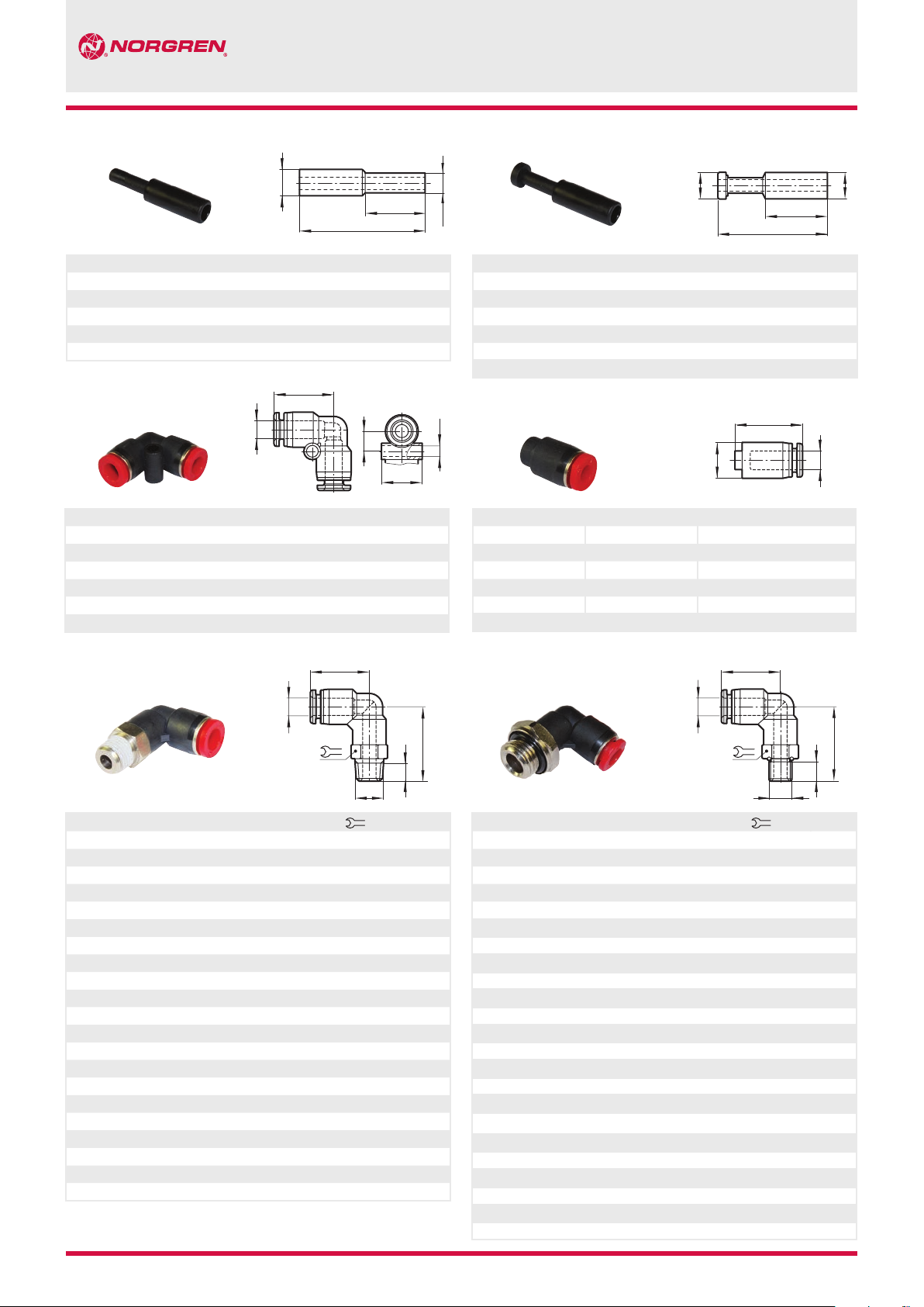
90° Swivel elbow adaptor
C0147
B
Ø A B C E G
4 R1/8 24,5 18,5 8 10 C01470418
4 R1/4 26,5 18,5 10 14 C01470428
4 R3/8 27,5 18,5 11 17 C01470438
6 R1/8 26,5 20,5 8 12 C01470618
6 R1/4 29,5 20,5 10 14 C01470628
6 R3/8 30,5 20,5 11 17 C01470638
6 R1/2 33,5 20,5 14 21 C01470648
8 R1/8 28 23 8 14 C01470818
8 R1/4 31 23 10 14 C01470828
8 R3/8 32 23 11 17 C01470838
8 R1/2 35 23 14 21 C01470848
10 R1/8 28,5 23,5 8 17 C01471018
10 R1/4 31,5 23,5 10 17 C01471028
10 R3/8 32,5 23,5 11 17 C01471038
10 R1/2 35,5 23,5 14 21 C01471048
12 R1/8 32,5 27,5 8 19 C01471218
12 R1/4 34,5 27,5 10 19 C01471228
12 R3/8 35,5 27,5 11 19 C01471238
12 R1/2 38,5 27,5 14 21 C01471248
16 R3/8 43 32,5 11 24 C01471638
16 R1/2 46 32,5 14 24 C01471648
N/en 9.1.020.08
Our policy is one of continued research and development. We therefore reserve the right to amend,
without notice, the specifications given in this document. © 2014 Norgren Ltd
G
Model
90° Swivel elbow adaptor
C0247
C
B
Ø A B C E G
4 M5 22 18,5 4,5 10 C02470405
4 M6 22 18,5 4,5 10 C02470406
4 G1/8 22,5 18,5 6 14 C02470418
4 G1/4 24,5 18,5 8 17 C02470428
4 G3/8 24,5 18,5 8 20 C02470438
6 M5 24 20,5 4,5 12 C02470605
6 M6 24 20,5 4,5 12 C02470606
6 G1/8 24,5 20,5 6 14 C02470618
6 G1/4 26,5 20,5 8 17 C02470628
6 G3/8 26,5 20,5 9 20 C02470638
8 G1/8 26 23 8 14 C02470818
8 G1/4 28 23 8 17 C02470828
8 G3/8 28 23 9 20 C02470838
8 G1/2 29 23 10 24 C02470848
10 G1/8 26,5 23,5 6 17 C02471018
10 G1/4 28,5 23,5 8 17 C02471028
10 G3/8 28,5 23,5 9 20 C02471038
10 G1/2 29,5 23,5 10 24 C02471048
12 G1/4 32,5 27,5 8 19 C02471228
12 G3/8 32,5 27,5 9 20 C02471238
12 G1/2 32,5 27,5 10 24 C02471248
16 G3/8 41 32,5 9 24 C02471638
16 G1/2 42 32,5 10 24 C02471648
2006-9005e 3/14
C
G
Model
Page 9

Pneufit® C
E
1
C
E
ø A
E
ø A
Stem elbow
C0043
ø A
ø A
Ø A Ø A1 C E F Model
4 4 28,5 19 22 C00430400
6 6 31,5 20,5 24 C00430600
8 8 34,5 23 26 C00430800
10 10 38 24 28 C00431000
12 12 41 28 30 C00431200
16 16 48,5 32 35 C00431600
90° Swivel elbow adaptor (extended)
C0154/C0254
B
90° Swivel elbow adaptor (female)
C0148/C0248
F
B
Ø A B C E G
4 M5 21,5 18,5 4,5 10 C02480405
4 M6 21,5 18,5 4,5 10 C02480406
4 R1/8 22,5 18,5 9 14 C01480418
4 R1/4 24,5 18,5 11 17 C01480428
6 M5 23,5 20,5 4,5 12 C02480605
6 M6 23,5 20,5 4,5 12 C02480606
6 R1/8 24,5 20,5 9 14 C01480618
6 R1/4 26,5 20,5 11 17 C01480628
6 R3/8 27,5 20,5 12 21 C01480638
8 R1/8 26 23 9 14 C01480818
8 R1/4 28 23 11 17 C01480828
8 R3/8 29 23 12 22 C01480838
10 R1/4 28,5 23,5 11 17 C01481028
10 R3/8 29,5 23,5 12 22 C01481038
C
10 R1/2 31,5 23,5 14 24 C01481048
12 R1/4 31,5 27,5 11 19 C01481228
G
12 R3/8 32,5 27,5 12 22 C01481238
12 R1/2 34,5 27,5 14 24 C01481248
C
G
Model
Ø A B C E G
4 M5 33,5 18,5 4,6 10 C02540405
4 M6 33 18,5 4,6 10 C02540406
4 R1/8 35,5 18,5 8 10 C01540418
4 R1/4 37,5 18,5 10 14 C01540428
4 R3/8 38,5 18,5 11 17 C01540438
6 M5 38 20,5 4,5 12 C02540605
6 M6 37,5 20,5 4,5 12 C02540606
6 R1/8 40 20,5 8 12 C01540618
6 R1/4 42 20,5 10 14 C01540628
6 R3/8 43 20,5 11 17 C01540638
6 R1/2 46 20,5 14 21 C01540648
8 R1/8 44 23 8 14 C01540818
8 R1/4 46 23 10 14 C01540828
8 R3/8 47 23 11 17 C01540838
8 R1/2 50 23 14 21 C01540848
10 R1/8 47,5 23,5 8 17 C01541018
10 R1/4 49,5 23,5 10 17 C01541028
10 R3/8 50,5 23,5 11 17 C01541038
10 R1/2 53,5 23,5 14 21 C01541048
12 R1/8 54 27,5 8 19 C01541218
12 R1/4 56 27,5 10 19 C01541228
12 R3/8 57 27,5 11 19 C01541238
12 R1/2 60 27,5 14 21 C01541248
16 R3/8 69 32,5 11 24 C01541638
16 R1/2 72 32,5 14 24 C01541648
Model
Bulkhead union elbow
E
C0049
ø A
P
ø A
B
Ø A B C E F G P Model
4 M12x1 32,5 18,5 5,5 9 4 14 C00490400
6 M14x1 38 20,5 6 11 4 17 C00490600
8 M16x1 40,5 23 6,5 11,5 5 19 C00490800
10 M20x1 42,5 23,5 7 12 5 24 C00491000
12 M22x1 48 27,5 7,5 15 5 26 C00491200
C
GF
3/14 2006-9005e N/en 9.1.020.09
Our policy is one of continued research and development. We therefore reserve the right to amend,
without notice, the specifications given in this document. © 2014 Norgren Ltd
Page 10

Pneufit® C
L
L
L
Union Y
C0082
ø A
L
D
H
C
O
Equal
Ø A Ø A1 C D H L O Model
4 4 37 3,3 14,5 10,5 10,5 C00820400
6 6 40 3,3 16,5 12,5 12,5 C00820600
8 8 43 4,3 18,5 14,5 14,5 C00820800
10 10 47,5 4,3 19 17,5 17,5 C00821000
12 12 53 4,3 22 20,5 20,5 C00821200
Unequal
Ø A Ø A1 C D H L O Model
4 6 38 3,3 15 10,5 10,5 C00820604
4 8 39,5 3,3 15 10,5 15 C00820804
6 8 41 4,3 16 12,5 13 C00820806
6 10 43 3,3 16,5 13 17,5 C00821006
8 10 43 4,3 17 14,5 15 C00821008
8 12 48 3,3 17,5 15 21 C00821208
10 12 46,5 4,3 18,5 17,5 18 C00821210
Swivel Y adaptor
C0188
ø A
C
Swivel Y adaptor
C0288
ø A
ø A1
C
Ø A B C G L
4 M5 35 4,5 10,5 10 C02880405
4 M6 35 4,5 10,5 10 C02880406
4 G1/8 41 6 10,5 14 C02880418
4 G1/4 43 8 10,5 17 C02880428
4 G3/8 43 8 10,5 20 C02880438
6 M5 41,5 4,5 12,5 12 C02880605
6 M6 41,5 4,5 12,5 12 C02880606
6 G1/8 42,5 6 12,5 14 C02880618
6 G1/4 44,5 8 12,5 17 C02880628
6 G3/8 45,5 9 12,5 20 C02880638
6 G1/2 46,5 10 12,5 24 C02880648
8 G1/8 43,5 6 14,5 14 C02880818
8 G1/4 45,5 8 14,5 17 C02880828
8 G3/8 46,5 9 14,5 20 C02880838
8 G1/2 47,5 10 14,5 24 C02880848
10 G1/8 49,5 6 17,5 17 C02881018
10 G1/4 51,5 8 17,5 17 C02881028
10 G3/8 52,5 9 17,5 20 C02881038
10 G1/2 53,5 10 17,5 24 C02881048
B
12 G1/4 55 8 20,5 19 C02881228
G
12 G3/8 56 9 20,5 20 C02881238
12 G1/2 57 10 20,5 24 C02881248
B
G
Model
Ø A B C G L
4 R1/8 41,5 8 10,5 10 C01880418
4 R1/4 42,5 10 10,5 14 C01880428
4 R3/8 43,5 11 10,5 17 C01880438
6 R1/8 44 8 12,5 12 C01880618
6 R1/4 47 10 12,5 14 C01880628
6 R3/8 48 11 12,5 17 C01880638
6 R1/2 51 14 12,5 21 C01880648
8 R1/8 45,5 8 14,5 14 C01880818
8 R1/4 48,5 10 14,5 14 C01880828
8 R3/8 48,5 11 14,5 17 C01880838
8 R1/2 52,5 14 14,5 21 C01880848
10 R1/8 49 8 17,5 17 C01881018
10 R1/4 52 10 17,5 17 C01881028
10 R3/8 53 11 17,5 17 C01881038
10 R1/2 56,2 14 17,5 21 C01881048
12 R1/8 52,5 3 20,5 19 C01881218
12 R1/4 54,5 8 20,5 19 C01881228
12 R3/8 55,5 11 20,5 19 C01881238
12 R1/2 58,5 14 20,5 22 C01881248
Model
Stem Y
C0084
ø A
ø A1
F
C
Equal
Ø A Ø A1 C F L Model
4 4 49,5 22 10,5 C00840400
6 6 54,5 24 12,5 C00840600
8 8 60 26 14,5 C00840800
10 10 66 28 17,5 C00841000
12 12 71,5 30 20,5 C00841200
Unequal
Ø A Ø A1 C F L Model
4 6 51,5 24 10,5 C00840604
6 8 56,5 26 12,5 C00840806
8 10 62 28 14,5 C00841008
10 12 68 30 17,5 C00841210
N/en 9.1.020.10
Our policy is one of continued research and development. We therefore reserve the right to amend,
without notice, the specifications given in this document. © 2014 Norgren Ltd
2006-9005e 3/14
Page 11

Pneufit® C
L
L
DG
L
DG
L
C
C 1
Quadruple stem reducer
C0096
ø A
D
H
C
O
Ø A Ø A1 C Ø D H L O Model
4 6 37 3,3 14 10,5 21 C00960604
6 8 40,5 3,3 15,5 12,5 25,5 C00960806
Quadruple Y union
C0195
ø A
H
C
Quadruple Y union
C0295
ø A
ø A1
H
Ø A B C Ø D G H L O * Model
4 G1/8 46 3,3 5 14 10,5 21 14 C02950418
4 G1/4 49 3,3 6,5 14 10,5 21 17 C02950428
6 G1/8 49 3,3 6,5 15,5 12,5 25,5 14 C02950618
6 G1/4 52 3,3 8 15,5 12,5 25,5 17 C02950628
* see drawing C0096 series
Quadruple reducer
C0097
B
ø A
D
H
B
C
ø A1
F
C
Ø A B C Ø D G H L O Model
4 R1/8 44 3,3 8 14 10,5 21 12 C01950418
4 R1/4 48 3,3 10 14 10,5 21 14 C01950428
6 R1/8 48 3,3 8 15,5 12,5 25,5 14 C01950618
6 R1/4 51 3,3 10 15,5 12,5 25,5 14 C01950628
* see drawing C0096 series
Union T (equal)
C0060
ø A
C 1
Ø A C C1 Ø D E G H O Model
4 36,5 19 3,3 13 12,5 8,5 10,5 C00600400
6 42 21,5 3,3 15 13,5 7,5 12,5 C00600600
8 45 23,5 4,3 18 15 9 14,5 C00600800
10 48 25,5 4,3 20 15,5 11 17,5 C00601000
12 57 29,5 4,3 26 16,5 12,5 20,5 C00601200
16 68 34,5 4,3 32 18 16 25,5 C00601600
C
ø A
E
H
G
O
Ø A Ø A1 C Ø D F H L O * Model
4 6 43,5 3,3 17 14 12,5 21 C00970604
6 8 48 3,3 19 15,5 14,5 25,5 C00970806
* see drawing C0096 series
Union T (unequal)
C006A
ø D
ø A
G
ø A1
E
Ø A Ø A1 C C1 Ø D E G H O Model
6 4 41,5 19 3,3 14 12,5 8 12,5 C006A0604
8 6 45 22 4,3 17 13,5 9,5 15 C006A0806
10 6 49 23 4,3 17 13,5 11 17,5 C006A1006
10 8 49 25 4,3 19 15 11 17,5 C006A1008
12 8 56 25,5 4,3 19 15 12,5 20,5 C006A1208
12 10 56 27,5 4,3 22 15,5 12,5 20,5 C006A1210
16 10 61 30,5 4,3 23 15,5 16 25,5 C006A1610
16 12 63,5 33 4,3 26 16,5 16 25,5 C006A1612
H
ø D
O
3/14 2006-9005e N/en 9.1.020.11
Our policy is one of continued research and development. We therefore reserve the right to amend,
without notice, the specifications given in this document. © 2014 Norgren Ltd
Page 12

Pneufit® C
ø A 1
ø A
C
E
C
ø A
Swivel tee adaptor
C0167
ø A
G
B
Ø A B C E G
4 R1/8 37,5 24,5 8 10 C01670418
4 R1/4 37,5 26,5 10 14 C01670428
4 R3/8 37,5 27,5 11 17 C01670438
6 R1/8 41 26,5 8 12 C01670618
6 R1/4 41 29,5 10 14 C01670628
6 R3/8 41 30,5 11 17 C01670638
6 R1/2 41 33,5 14 21 C01670648
8 R1/8 44 28 8 14 C01670818
8 R1/4 44 31 10 14 C01670828
8 R3/8 44 32 11 17 C01670838
8 R1/2 44 35 14 21 C01670848
10 R1/8 47 28,5 8 17 C01671018
10 R1/4 47 32 10 17 C01671028
10 R3/8 47 32,5 11 17 C01671038
10 R1/2 47 35,5 14 21 C01671048
12 R1/8 55 32,5 8 19 C01671218
12 R1/4 55 34,5 10 19 C01671228
12 R3/8 55 35,5 11 19 C01671238
12 R1/2 55 38,5 14 21 C01671248
16 R3/8 64,5 43 11 24 C01671638
16 R1/2 64,5 46 14 24 C01671648
Model
Swivel tee adaptor (female)
C016C/C026C
Swivel tee adaptor
C
C0267
ø A
E
G
B
Ø A B C E G
4 M5 37,5 22 4,5 10 C02670405
4 M6 37,5 22 4,5 10 C02670406
4 G1/8 37,5 22 6 14 C02670418
4 G1/4 37,5 24 8 17 C02670428
4 G3/8 37,5 24 8 20 C02670438
6 M5 41 24 4,5 12 C02670605
6 M6 41 24 4,5 12 C02670606
6 G1/8 41 24,5 6 14 C02670618
6 G1/4 41 26,5 8 17 C02670628
6 G3/8 41 27,5 9 20 C02670638
6 G1/2 41 28,5 9 24 C02670648
8 G1/8 44,5 26 6 14 C02670818
8 G1/4 44,5 28 8 17 C02670828
8 G3/8 44,5 29 9 20 C02670838
8 G1/2 44,5 30 10 24 C02670848
10 G1/8 47 26,5 6 17 C02671018
10 G1/4 47 28,5 8 17 C02671028
10 G3/8 47 29,5 9 20 C02671038
10 G1/2 47 30,5 10 24 C02671048
12 G1/4 55 31,5 8 19 C02671228
12 G3/8 55 32,5 9 20 C02671238
12 G1/2 55 33,5 10 24 C02671248
16 G3/8 64,5 40 9 24 C02671638
16 G1/2 64,5 41 10 24 C02671648
Model
Stem tee
C0063
E
G
B
C
Ø A B C E G
4 M5 37,5 17 8 10 C026C0405
4 M6 37,5 17 8 10 C026C0406
4 R1/8 38 17 9 14 C016C0418
4 R1/4 38 17 11 17 C016C0428
6 M5 41 17,5 8 12 C026C0605
6 M6 41 17,5 8 12 C026C0606
6 R1/8 41 17,5 9 14 C016C0618
6 R1/4 41 17,5 11 17 C016C0628
6 R3/8 41 17,5 12 22 C016C0638
8 R1/8 44,5 18,5 9 14 C016C0818
8 R1/4 44,5 18,5 11 17 C016C0828
8 R3/8 44,5 18,5 12 22 C016C0838
8 R1/2 44,5 18,5 14 24 C016C0848
10 R1/8 47 19,5 9 17 C016C1018
10 R1/4 47 19,5 11 17 C016C1028
10 R3/8 47 19,5 12 22 C016C1038
10 R1/2 47 19,5 14 24 C016C1048
12 R1/4 55 22 11 19 C016C1228
12 R3/8 55 22 12 22 C016C1238
12 R1/2 55 22 14 24 C016C1248
N/en 9.1.020.12
Our policy is one of continued research and development. We therefore reserve the right to amend,
without notice, the specifications given in this document. © 2014 Norgren Ltd
Model
F
Equal
Ø A Ø A1 C E F Model
4 4 37,5 32,5 24 C00630400
6 6 41 34,5 25 C00630600
8 8 44,5 36 26 C00630800
10 10 47 37,5 28 C00631000
12 12 55 39 30 C00631200
E
Unequal
Ø A Ø A1 C E F
4 6 37,5 33,5 25 C00630604
6 8 41 35,5 28 C00630806
8 10 44,5 38,5 28 C00631008
10 12 47 39,5 30 C00631210
2006-9005e 3/14
Model
Page 13

Pneufit® C
E
ø A
E
ø A
C
Stem side tee
C0064
Equal
Ø A Ø A1 C E F Model
4 4 58 20,5 17 C00640400
6 6 52,5 21,5 17,5 C00640600
8 8 67 23,5 18,5 C00640800
10 10 73 25,5 19,5 C00641000
12 12 82 30 22 C00641200
Unequal
Ø A Ø A1 C E F Model
4 6 59 20 17 C00640604
6 8 63,5 21,5 17,5 C00640806
8 10 69,5 23,5 18,5 C00641008
10 12 75 25,5 19,5 C00641210
Swivel side tee adaptor
C0168
G
B
Ø A B C E G
4 R1/8 45 20 8 10 C01680418
4 R1/4 48 20 10 14 C01680428
4 R3/8 49 20 11 17 C01680438
6 R1/8 48,5 21,5 8 12 C01680618
6 R1/4 51 21,5 10 14 C01680628
6 R3/8 52 21,5 11 17 C01680638
6 R1/2 55 21,5 14 21 C01680648
8 R1/8 52 23,5 8 14 C01680818
8 R1/4 55 23,5 10 14 C01680828
8 R3/8 56 23,5 11 17 C01680838
8 R1/2 59 23,5 14 21 C01680848
10 R1/8 55,5 25,5 8 17 C01681018
10 R1/4 58,5 25,5 10 17 C01681028
10 R3/8 59,5 25,5 11 17 C01681038
10 R1/2 62,5 25,5 14 21 C01681048
12 R1/8 63 30 8 19 C01681218
12 R1/4 65 30 10 19 C01681228
12 R3/8 66 30 11 19 C01681238
12 R1/2 69 30 14 21 C01681248
F
ø A 1
Model
Swivel side tee adaptor
C0268
C
Ø A B C E G
4 M5 42 20 4,5 10 C02680405
4 M6 42 20 4,5 10 C02680406
4 G1/8 43 20 6 14 C02680418
4 G1/4 45 20 8 17 C02680428
4 G3/8 45 20 8 20 C02680438
6 M5 46 21,5 4,5 12 C02680605
6 M6 46 21,5 4,5 12 C02680606
6 G1/8 47 21,5 6 14 C02680618
6 G1/4 49 21,5 8 17 C02680628
6 G3/8 50 21,5 9 20 C02680638
8 G1/8 50 23,5 6 14 C02680818
8 G1/4 52 23,5 8 17 C02680828
8 G3/8 56 23,5 9 20 C02680838
8 G1/2 54 23,5 10 24 C02680848
10 G1/8 54 25,5 6 17 C02681018
10 G1/4 56 25,5 8 17 C02681028
10 G3/8 57 25,5 9 20 C02681038
10 G1/2 58 25,5 10 24 C02681048
12 G1/4 62 30 8 19 C02681228
12 G3/8 63 30 9 20 C02681238
12 G1/2 64 30 10 24 C02681248
ø A
Union cross
E
ø A
C
G
B
Model
C
C0090
C 1
ø A
E
H
Ø A C C1 Ø D E H O Model
4 36,5 38 3,3 13 6,5 10,5 C00900400
6 42 42,5 4,3 15 7,5 12,5 C00900600
8 45 47 4,3 18 9 14,5 C00900800
10 48 50,5 4,3 20 10 17,5 C00901000
12 55 57 4,3 24 12 20,5 C00901200
ø D
O
3/14 2006-9005e N/en 9.1.020.13
Our policy is one of continued research and development. We therefore reserve the right to amend,
without notice, the specifications given in this document. © 2014 Norgren Ltd
Page 14

Pneufit® C
C
B
C
ø A2
C
C 1
C
C 1
Manifold union
C
C00D3
ø A
H
Ø A Ø A1 C C1 D E H L O Model
4 6 63,5 18 3,3 34 7,5 10,5 12,5 C00D30604
4 8 65,5 21,5 4,3 35 9 10,5 14,5 C00D30804
6 8 71,5 22,5 4,3 41 9,5 12,5 14,5 C00D30806
6 10 78 23,5 4,3 42 9,5 12,5 17,5 C00D31006
8 10 83,5 26 4,3 47 9,5 14,5 17,5 C00D31008
L
E
ø A1
O
ø D
Male manifold
C01D3
G
ø A
L
E
Banjo
C0A51
C 1
Ø A B C C1 E G Model
4 M5 25 18 10 3,5 8 C0A510405
4 G1/8 30,5 25 14,5 11 8 C0A510418
4 G1/4 34,5 29 16,5 10 8 C0A510428
6 M5 18 28 11 3,5 8 C0A510605
6 G1/8 31 25 14,5 8 8 C0A510618
6 G1/4 35 29 16,5 10 12 C0A510628
6 G3/8 38,5 32,5 20,5 11 14 C0A510638
8 G1/8 33 25 13,5 8 8 C0A510818
8 G1/4 37 29 16 10 12 C0A510828
8 G3/8 40 32,5 20,5 11 14 C0A510838
ø A 1
8 G1/2 46 39,5 23 14 17 C0A510848
10 G1/4 39 29 15,5 10 12 C0A511028
10 G3/8 42 32,5 19,5 11 14 C0A511038
10 G1/2 47,5 39,5 23 14 17 C0A511048
C 1
12 G3/8 46 32,5 18,5 11 14 C0A511238
12 G1/2 50 39,5 21,5 14 17 C0A511248
Banjo (with top port)
C0D51/C0E51/C0F51/C0G51
ø A
E
G
B
B 1
Ø A Ø A1 B C C1 E G L Model
4 6 R1/8 72 24 34 8 10,5 12 C01D30418
4 8 R1/8 74 28,5 35 8 10,5 14 C01D30428
6 8 R1/4 82,5 34 41 10 12,5 14 C01D30628
8 10 R3/8 95 34,5 47 10 14,5 17 C01D30838
Stem manifold
C00J3
Ø A Ø A1 Ø A2 C C1 E F L Model
4 6 6 84,5 24 34 25 10,5 C00J30604
4 8 8 89,5 28,5 35 28,5 10,5 C00J30804
6 8 8 95,5 34 41 28,5 12,5 C00J30806
8 10 10 109,5 34,5 47 31 14,5 C00J31008
C1
F
ø A1
L
E
G1G
ø A
E
B
Ø A B & B1 C C1 E G G1 Model
ø A
4 M5 25 20 10 3,5 6 8 C0D510405
4 R1/8 30,5 30 14,5 9 8 14 C0E510418
4 R1/4 34,5 35,5 18 11 10 17 C0F510428
6 M5 28 20 11 3,5 6 8 C0D510605
6 R1/8 31 30 14,5 9 8 14 C0E510618
6 R1/4 35 35,5 18 11 10 17 C0F510628
6 R3/8 38,5 41 21 12 11 21 C0G510638
8 R1/8 33 30 15,5 9 8 14 C0E510818
8 R1/4 38 35,5 19 11 10 17 C0F510828
8 R3/8 40 41 21 12 11 21 C0G510838
10 R1/4 39 35,5 20 11 10 17 C0F511028
10 R3/8 42 41 22,5 12 11 21 C0G511038
12 R3/8 46 41 23 12 11 21 C0G511238
N/en 9.1.020.14
Our policy is one of continued research and development. We therefore reserve the right to amend,
without notice, the specifications given in this document. © 2014 Norgren Ltd
2006-9005e 3/14
Page 15

Pneufit® C
B
ø A
C
B
C
B
2x Swivel elbow adaptor
C0Q51
G
Ø A B C E G H J Model
4 R1/8 52 24 8 22,5 18 14 C0Q510418
4 R1/4 63 26 10 27,5 22 17 C0Q510428
4 R3/8 65 28 11 29 22 21 C0Q510438
4 R1/2 74 30 14 34 24 24 C0Q510448
6 R1/8 52 25 8 22,5 18 14 C0Q510618
6 R1/4 63 27 10 27,5 22 17 C0Q510628
6 R3/8 65 28,5 11 29 22 21 C0Q510638
6 R1/2 74 30 14 34 24 24 C0Q510648
8 R1/8 52 27 8 22,5 18 14 C0Q510818
8 R1/4 63 28,5 10 27,5 22 17 C0Q510828
8 R3/8 65 30,5 11 29 22 21 C0Q510838
8 R1/2 74 32 14 34 24 24 C0Q510848
10 R1/8 52 28,5 8 22,5 18 14 C0Q511018
10 R1/4 63 30,5 10 27,5 22 17 C0Q511028
10 R3/8 65 32,5 11 29 22 21 C0Q511038
10 R1/2 74 34,5 14 34 24 24 C0Q511048
12 R1/4 63 36 10 27,5 22 17 C0Q511228
12 R3/8 65 36 11 29 22 21 C0Q511238
12 R1/2 74 38 14 34 24 24 C0Q511248
C
JH
ø A
3x Swivel elbow adaptor
C0H51
E
Ø A B C E G H J Model
4 R1/8 70 24 8 22,5 18 14 C0H510418
4 R1/4 85 26 10 27,5 22 17 C0H510428
4 R3/8 87 28 11 29 22 21 C0H510438
4 R1/2 97,5 30 14 34 24 24 C0H510448
6 R1/8 70 25 8 22,5 18 14 C0H510618
6 R1/4 85 27 10 27,5 22 17 C0H510628
6 R3/8 87 28,5 11 29 22 21 C0H510638
6 R1/2 97,5 30 14 34 24 24 C0H510648
8 R1/8 70 27 8 22,5 18 14 C0H510818
8 R1/4 85 28,5 10 27,5 22 17 C0H510828
8 R3/8 87 30,5 11 29 22 21 C0H510838
8 R1/2 97,5 32 14 34 24 24 C0H510848
10 R1/8 70 28,5 8 22,5 18 14 C0H511018
10 R1/4 85 30,5 10 27,5 22 17 C0H511028
10 R3/8 87 32,5 11 29 22 21 C0H511038
10 R1/2 97,5 34,5 14 34 24 24 C0H511048
12 R1/4 85 36 10 27,5 22 17 C0H511228
12 R3/8 87 36 11 29 22 21 C0H511238
12 R1/2 87,5 38 14 34 24 24 C0H511248
H
G
J
E
2x Swivel elbow adaptor
C0B51
G
B
Ø A B C E G H J Model
4 G1/8 50 24 5 20,5 18 14 C0B510418
4 G1/4 61 26 6,5 25,5 22 17 C0B510428
4 G3/8 62 28 6,5 26 22 21 C0B510438
4 G1/2 70 30 8 29,5 24 24 C0B510448
6 G1/8 50 25 5 20,5 18 14 C0B510618
6 G1/4 61 27 6,5 25,5 22 17 C0B510628
6 G3/8 62 28,5 6,5 26 22 21 C0B510638
6 G1/2 70 30 8 29,5 24 24 C0B510648
8 G1/8 50 27 5 20,5 18 14 C0B510818
8 G1/4 61 28,5 6,5 25,5 22 17 C0B510828
8 G3/8 62 30,5 6,5 26 22 21 C0B510838
8 G1/2 70 32 8 29,5 24 24 C0B510848
10 G1/8 50 28,5 5 20,5 18 14 C0B511018
10 G1/4 61 30,5 6,5 25,5 22 17 C0B511028
10 G3/8 62 32,5 6,5 26 22 21 C0B511038
10 G1/2 70 34,5 8 29,5 24 24 C0B511048
12 G1/4 61 36 6,5 25,5 22 17 C0B511228
12 G3/8 62 36 6,5 26 22 21 C0B511238
12 G1/2 70 38 8 29,5 24 24 C0B511248
C
H
J
ø A
3x Swivel elbow adaptor
C0C51
G
E
Ø A B C E G H J Model
4 G1/8 68 24 5 20,5 18 14 C0C510418
4 G1/4 83 26 6,5 25,5 22 17 C0C510428
4 G3/8 84 28 6,5 26 22 21 C0C510438
4 G1/2 93 30 8 29,5 24 24 C0C510448
6 G1/8 68 25 5 20,5 18 14 C0C510618
6 G1/4 83 27 6,5 25,5 22 17 C0C510628
6 G3/8 84 28,5 6,5 26 22 21 C0C510638
6 G1/2 93 30 8 29,5 24 24 C0C510648
8 G1/8 68 27 5 20,5 18 14 C0C510818
8 G1/4 83 28,5 6,5 25,5 22 17 C0C510828
8 G3/8 84 30,5 6,5 26 22 21 C0C510838
8 G1/2 93 32 8 29,5 24 24 C0C510848
10 G1/8 68 28,5 5 20,5 18 14 C0C511018
10 G1/4 83 30,5 6,5 25,5 22 17 C0C511028
10 G3/8 84 32,5 6,5 26 22 21 C0C511038
10 G1/2 83 34,5 8 29,5 24 24 C0C511048
12 G1/4 83 34 6,5 25,5 22 17 C0C511228
12 G3/8 84 35 6,5 26 22 21 C0C511238
12 G1/2 93 38 8 29,5 24 24 C0C511248
JH
E
ø A
3/14 2006-9005e N/en 9.1.020.15
Our policy is one of continued research and development. We therefore reserve the right to amend,
without notice, the specifications given in this document. © 2014 Norgren Ltd
Page 16

Pneufit® C
C
E
C
B
C
B
Single universal tee
C0N71
C
E
H
G
B
Ø A B C E G H Model
4 R1/8 47 34 8 25,5 14 C0N710418
4 R1/4 50,5 41 10 27,5 17 C0N710428
4 R3/8 54,5 43 11 29 21 C0N710438
4 R1/2 58,5 50 14 34 24 C0N710448
6 R1/8 48,5 34 8 22,5 14 C0N710618
6 R1/4 52 41 10 27,5 17 C0N710628
6 R3/8 56 43 11 29 21 C0N710638
6 R1/2 58,5 50 14 34 24 C0N710648
8 R1/8 52 34 8 22,5 14 C0N710818
8 R1/4 55,5 41 10 27,5 17 C0N710828
8 R3/8 59,5 43 11 29 21 C0N710838
8 R1/2 63,5 50 14 34 24 C0N710848
10 R1/8 56 34 8 22,5 14 C0N711018
10 R1/4 59,5 41 10 27,5 17 C0N711028
10 R3/8 63,5 43 11 29 21 C0N711038
10 R1/2 67 50 14 34 24 C0N711048
12 R1/4 66 41 10 27,5 17 C0N711228
12 R3/8 70 43 11 29 21 C0N711238
12 R1/2 74,5 50 14 34 24 C0N711248
Double universal tee
C0Q71
ø A
Ø A B C E G H J Model
4 R1/8 52 47 8 22,5 18 14 C0Q710418
4 R1/4 63 50,5 10 27,5 22 17 C0Q710428
4 R3/8 65 54,5 11 29 22 21 C0Q710438
4 R1/2 74 58,5 14 34 24 24 C0Q710448
6 R1/8 52 48,5 8 22,5 18 14 C0Q710618
6 R1/4 63 52 10 27,5 22 17 C0Q710628
6 R3/8 65 56 11 29 22 21 C0Q710638
6 R1/2 74 58,5 14 34 24 24 C0Q710648
8 R1/8 52 52 8 22,5 18 14 C0Q710818
8 R1/4 63 55,5 10 27,5 22 17 C0Q710828
8 R3/8 65 59,5 11 29 22 21 C0Q710838
8 R1/2 74 62,5 14 34 24 24 C0Q710848
10 R1/8 52 56 8 22,5 18 14 C0Q711018
10 R1/4 63 59,5 10 27,5 22 17 C0Q711028
10 R3/8 65 63,5 11 29 22 21 C0Q711038
10 R1/2 74 67 14 34 24 24 C0Q711048
12 R1/4 63 66 10 27,5 21 17 C0Q711228
12 R3/8 65 70 11 29 21 21 C0Q711238
12 R1/2 74 74,5 14 34 24 24 C0Q711248
H
G
J
E
ø A
Single universal tee
C0A71
H
G
B
Ø A B C E G H Model
4 G1/8 47 32 5 20,5 14 C0A710418
4 G1/4 50,5 39 6,5 25,5 17 C0A710428
4 G3/8 54,5 40 6,5 26 21 C0A710438
4 G1/2 58,5 45,5 8 29,5 24 C0A710448
6 G1/8 48,5 32 5 20,5 14 C0A710618
6 G1/4 52 39 6,5 25,5 17 C0A710628
6 G3/8 56 40 6,5 26 21 C0A710638
6 G1/2 58,5 45,5 8 29,5 24 C0A710648
8 G1/8 52 32 5 20,5 14 C0A710818
8 G1/4 55,5 39 6,5 25,5 17 C0A710828
8 G3/8 59,5 40 6,5 26 21 C0A710838
8 G1/2 62,5 45,5 8 29,5 24 C0A710848
10 G1/8 56 32 5 20,5 14 C0A711018
10 G1/4 59,5 39 6,5 25,5 17 C0A711028
10 G3/8 63,5 40 6,5 26 21 C0A711038
10 G1/2 67 45,5 8 29,5 24 C0A711048
12 G1/4 66 39 6,5 25,5 17 C0A711228
12 G3/8 70 40 6,5 26 21 C0A711238
12 G 1/2 74,5 45,5 8 29,5 24 C0A711248
N/en 9.1.020.16
Our policy is one of continued research and development. We therefore reserve the right to amend,
without notice, the specifications given in this document. © 2014 Norgren Ltd
Double universal tee
C0B71
ø A
Ø A B C E G H J Model
4 G1/8 50 47 5 20,5 18 14 C0B710418
4 G1/4 61 50,5 6,5 25,5 22 17 C0B710428
4 G3/8 62 54,5 6,5 26 22 21 C0B710438
4 G1/2 69,5 58,5 8 29,5 24 24 C0B710448
6 G1/8 50 48,5 5 20,5 18 14 C0B710618
6 G1/4 61 52 6,5 25,5 22 17 C0B710628
6 G3/8 62 56 6,5 26 22 21 C0B710638
6 G1/2 69,5 58,5 8 29,5 24 24 C0B710648
8 G1/8 50 52 5 20,5 18 14 C0B710818
8 G1/4 61 55,5 6,5 25,5 22 17 C0B710828
8 G3/8 62 59,5 6,5 26 22 21 C0B710838
8 G1/2 69,5 62,5 8 29,5 24 24 C0B710848
10 G1/8 50 56 5 20,5 18 14 C0B711018
10 G1/4 61 59,5 6,5 25,5 22 17 C0B711028
10 G3/8 62 63,5 6,6 26 22 21 C0B711038
10 G1/2 69,5 67 8 29,5 24 24 C0B711048
12 G1/4 61 66 6,5 25,5 21 17 C0B711228
12 G3/8 62 70 6,5 26 21 21 C0B711238
12 G 1/2 69,5 74,5 8 29,5 24 24 C0B711248
H
G
2006-9005e 3/14
J
ø A
E
Page 17

Pneufit® C
C
B
C
B
C
E
C
E
Triple universal tee
C0H71
Ø A B C E G H J Model
4 R1/8 70 47 8 22,5 18 14 C0H710418
4 R1/4 85 50,5 10 27,5 22 17 C0H710428
4 R3/8 87 54,5 11 29 22 21 C0H710438
4 R1/2 97,5 58,5 14 34 24 24 C0H710448
6 R1/8 70 48,5 8 22,5 18 14 C0H710618
6 R1/4 85 52 10 27,5 22 17 C0H710628
6 R3/8 87 56 11 29 22 21 C0H710638
6 R1/2 97,5 58,5 14 34 24 24 C0H710648
8 R1/8 70 52 8 22,5 18 14 C0H710818
8 R1/4 85 55,5 10 27,5 22 17 C0H710828
8 R3/8 87 59,5 11 29 22 21 C0H710838
8 R1/2 97,5 62,5 14 34 24 24 C0H710848
10 R1/8 70 56 8 22,5 18 14 C0H711018
10 R1/4 85 59,5 10 27,5 22 17 C0H711028
10 R3/8 87 63,5 11 29 22 21 C0H711038
10 R1/2 97,5 67 14 34 24 24 C0H711048
12 R1/4 85 66 10 27,5 21 17 C0H711228
12 R3/8 87 70 11 29 21 21 C0H711238
12 R1/2 97,5 74,5 14 34 24 24 C0H711248
H
G
J
ø A
Branch adaptor
C0N70
H
E
Ø A B C E G H L Model
6 R1/8 25 23 8 14,5 12,5 11 C0N700618
8 R1/4 29 28,5 10 18,5 15 15 C0N700828
10 R1/4 29 31 10 19,5 17,5 15 C0N701028
10 R3/8 32,5 31 11 20,5 17,5 19 C0N701038
12 R3/8 32,5 36 11 22 20,5 19 C0N701238
12 R1/2 39,5 36,5 14 25,5 20,5 24 C0N701248
G
B
Branch adaptor
C0A70
H
G
B
ø A
L
ø A
Triple universal tee
C0C71
G
Ø A B C E G H J Model
4 G1/8 68 47 5 20,5 18 14 C0C710418
4 G1/4 83 50,5 6,5 25,5 22 17 C0C710428
4 G3/8 84 54,5 6,5 26 22 21 C0C710438
4 G1/2 93 58,5 8 29,5 24 24 C0C710448
6 G1/8 68 48,5 5 20,5 18 14 C0C710618
6 G1/4 83 52 6,5 25,5 22 17 C0C710628
6 G3/8 84 56 6,5 26 22 21 C0C710638
6 G1/2 93 58,5 8 29,5 24 24 C0C710648
8 G1/8 68 52 5 20,5 18 14 C0C710818
8 G1/4 83 55,5 6,5 25,5 22 17 C0C710828
8 G3/8 84 59,5 6,5 26 22 21 C0C710838
8 G1/2 93 62,5 8 29,5 24 24 C0C710848
10 G1/8 68 56 5 20,5 18 14 C0C711018
10 G1/4 83 59,5 6,5 25,5 22 17 C0C711028
10 G3/8 84 63,5 6,6 26 22 21 C0C711038
10 G1/2 93 67 8 29,5 24 24 C0C711048
12 G1/4 83 66 6,5 25,5 21 17 C0C711228
12 G3/8 84 70 6,5 26 21 21 C0C711238
12 G 1/2 93 74,5 8 29,5 24 24 C0C711248
JH
Ø A B C E G H L Model
E
4 M5 18 19,5 3,6 10 10,5 8 C0A700405
6 G1/8 23,5 23 4,5 14 12,5 8 C0A700618
8 G1/4 28 28,5 6 17,5 15 12 C0A700828
ø A
10 G1/4 28 31 6 19 17,5 12 C0A701028
10 G3/8 32,5 31 6 21 17,5 14 C0A701038
12 G3/8 32,5 36 6 22,5 20,5 14 C0A701238
12 G1/2 34 36,5 7,5 23 20,5 17 C0A701248
L
3/14 2006-9005e N/en 9.1.020.17
Our policy is one of continued research and development. We therefore reserve the right to amend,
without notice, the specifications given in this document. © 2014 Norgren Ltd
Page 18

Pneufit® C
C
C
B
E
Branch adaptor (female)
C0*7J
G1
C
H
G
Ø A B C E G / G1 H L Model
6 R1/8 30 23 8 14,5 12,5 14 C0E7J0618
8 R1/4 35,5 28,5 10 18,5 15 17 C0F7J0828
10 R1/4 35,5 31 10 19,5 17,5 17 C0F7J1028
10 R3/8 41 31 11 20,5 17,5 21 C0G7J1038
12 R3/8 41 36 11 22 20,5 21 C0G7J1238
12 R1/2 50 36,5 14 25,5 20,5 24 C0H7J1248
E
B
B
Branch adaptor (female)
C0*7K
C
H
B
G1
G
B
Double branch adaptor
C0Q70
G
ø A
Ø A B C E G H J Model
L
4 R1/8 52 24 8 22,5 18 14 C0Q700418
4 R1/4 63 26 10 27,5 22 17 C0Q700428
4 R3/8 65 28 11 29 22 21 C0Q700438
4 R1/2 74 30,5 14 34 24 24 C0Q700448
6 R1/8 52 25 8 22,5 18 14 C0Q700618
6 R1/4 63 27 10 27,5 22 17 C0Q700628
6 R3/8 65 28,5 11 29 22 21 C0Q700638
6 R1/2 74 31 14 34 24 24 C0Q700648
8 R1/8 52 27 8 22,5 18 14 C0Q700818
8 R1/4 63 30,5 10 27,5 22 17 C0Q700828
8 R3/8 65 30,5 11 29 22 21 C0Q700838
8 R1/2 74 32,5 14 34 24 24 C0Q700848
10 R1/8 52 28,5 8 22,5 18 14 C0Q701018
10 R1/4 63 30,5 10 27,5 22 17 C0Q701028
10 R3/8 65 32,5 11 29 22 21 C0Q701038
10 R1/2 74 35 14 34 24 24 C0Q701048
ø A
12 R1/4 63 34 10 27,5 22 17 C0Q701228
12 R3/8 65 35 11 29 22 21 C0Q701238
12 R1/2 74 39 14 34 24 24 C0Q701248
B
Double branch adaptor
C0B70
L
H
G
JH
E
ø A
J
Ø A B C E G / G1 H L Model
4 M5 20 19,5 3,5 / 7 10 10,5 8 C0D7K0405
6 G1/8 30 23 8 14 12,5 14 C0E7K0618
8 G1/4 35,5 27 10 17,5 14,5 17 C0F7K0828
10 G1/4 35,5 28 10 17,5 17,5 17 C0F7K1028
10 G3/8 41 30 11 17,5 17,5 21 C0G7K1038
12 G3/8 41 33 11 17,5 20,5 21 C0G7K1238
12 G1/2 50 35 14 20 20,5 24 C0H7K1248
Ø A B C E G H J Model
4 G1/8 50 24 5 20,5 18 14 C0B700418
4 G1/4 61 26 6,5 25,5 22 17 C0B700428
4 G3/8 62 28 6,5 26 22 21 C0B700438
4 G1/2 69,5 30,5 8 29,5 24 24 C0B700448
6 G1/8 50 25 5 20,5 18 14 C0B700618
6 G1/4 61 27 6,5 25,5 22 17 C0B700628
6 G3/8 62 28,5 6,5 26 22 21 C0B700638
6 G1/2 69,5 31 8 29,5 24 24 C0B700648
8 G1/8 50 27 5 20,5 18 14 C0B700818
8 G1/4 61 30,5 6,5 25,5 22 17 C0B700828
8 G3/8 62 30,5 6,5 26 22 21 C0B700838
8 G1/2 69,5 32,5 8 29,5 24 24 C0B700848
10 G1/8 50 28,5 5 20,5 18 14 C0B701018
10 G1/4 61 30,5 6,5 25,5 22 17 C0B701028
10 G3/8 62 32,5 6,5 26 22 21 C0B701038
10 G1/2 69,5 35 8 29,5 24 24 C0B701048
12 G1/4 61 34 6,5 25,5 22 17 C0B701228
12 G3/8 62 35 6,5 26 22 21 C0B701238
12 G 1/2 69,5 39 8 29,5 24 24 C0B701248
ø A
E
N/en 9.1.020.18
Our policy is one of continued research and development. We therefore reserve the right to amend,
without notice, the specifications given in this document. © 2014 Norgren Ltd
2006-9005e 3/14
Page 19

Pneufit® C
ø A
C
B
B
1
2
C
C 1
1
2
C
C 1
Triple branch adaptor
C0H70
Ø A B C E G H J Model
4 R1/8 52 24 8 22,5 18 14 C0H700418
4 R1/4 63 26 10 27,5 22 17 C0H700428
4 R3/8 65 28 11 29 22 21 C0H700438
4 R1/2 74 30,5 14 34 24 24 C0H700448
6 R1/8 52 25 8 22,5 18 14 C0H700618
6 R1/4 63 27 10 27,5 22 17 C0H700628
6 R3/8 65 28,5 11 29 22 21 C0H700638
6 R1/2 74 31 14 34 24 24 C0H700648
8 R1/8 52 27 8 22,5 18 14 C0H700818
8 R1/4 63 30,5 10 27,5 22 17 C0H700828
8 R3/8 65 30,5 11 29 22 21 C0H700838
8 R1/2 74 32,5 14 34 24 24 C0H700848
10 R1/8 52 28,5 8 22,5 18 14 C0H701018
10 R1/4 63 30,5 10 27,5 22 17 C0H701028
10 R3/8 65 32,5 11 29 22 21 C0H701038
10 R1/2 74 35 14 34 24 24 C0H701048
12 R1/4 63 34 10 27,5 22 17 C0H701228
12 R3/8 65 35 11 29 22 21 C0H701238
12 R1/2 74 39 14 34 24 24 C0H701248
H
G
J
Banjo flow control (out)
C0TA0
E
Ø A B C > C1 < C1 E G Model
4 R1/8 30,5 35 40 14,5 8 11 C0TA00418
4 R1/4 34,5 40 45,5 18 10 15 C0TA00428
6 R1/8 31 35 31 14,5 8 11 C0TA00618
6 R1/4 35 40 45,5 18 10 15 C0TA00628
6 R3/8 38,5 46,5 55 21 11 19 C0TA00638
8 R1/8 33 35 40 15,5 8 11 C0TA00818
8 R1/4 37 40 45,5 19 10 15 C0TA00828
8 R3/8 40 46,5 55 21 11 19 C0TA00838
8 R1/2 46 53 60 25 14 24 C0TA00848
10 R1/4 39 40 45,5 20 10 15 C0TA01028
10 R3/8 42 46,5 55 22,5 11 19 C0TA01038
10 R1/2 47,5 53 60 25 14 24 C0TA01048
12 R1/4 41 40 45,5 22 10 15 C0TA01228
12 R3/8 46 46,5 55 23 11 19 C0TA01238
12 R1/2 50 53 60 27 14 24 C0TA01248
E
G
1
B
Banjo flow control (out)
C0K51
2
ø A
Triple branch adaptor
C0C70
G
Ø A B C E G H J Model
4 G1/8 68 24 5 20,5 18 14 C0C700418
4 G1/4 83 26 6,5 25,5 22 17 C0C700428
4 G3/8 84 28 6,5 26 22 21 C0C700438
4 G1/2 93 30,5 8 29,5 24 24 C0C700448
6 G1/8 68 25 5 20,5 18 14 C0C700618
6 G1/4 83 27 6,5 25,5 22 17 C0C700628
6 G3/8 84 28,5 6,5 26 22 21 C0C700638
6 G1/2 93 31 8 29,5 24 24 C0C700648
8 G1/8 68 27 5 20,5 18 14 C0C700818
8 G1/4 83 30,5 6,5 25,5 22 17 C0C700828
8 G3/8 84 30,5 6,5 26 22 21 C0C700838
8 G1/2 93 32,5 8 29,5 24 24 C0C700848
10 G1/8 68 28,5 5 20,5 18 14 C0C701018
10 G1/4 83 30,5 6,5 25,5 22 17 C0C701028
10 G3/8 84 32,5 6,5 26 22 21 C0C701038
10 G1/2 93 35 8 29,5 24 24 C0C701048
12 G1/4 83 34 6,5 25,5 22 17 C0C701228
12 G3/8 84 35 6,5 26 22 21 C0C701238
12 G 1/2 93 39 8 29,5 24 24 C0C701248
C
JH
ø A
E
G
1
E
Ø A B C > C1 < C1 E G Model
3 M5 21,5 27 30 9,5 3,5 8 C0K510305
4 M5 25 27 30 10 3,5 8 C0K510405
4 G1/8 30,5 35 40 15 6 8 C0K510418
4 G1/4 34,5 40 45,5 17 8 12 C0K510428
6 M5 28 27 30 11 3,5 8 C0K510605
6 G1/8 31 35 40 15 6 8 C0K510618
6 G1/4 35 40 45,5 17 8 12 C0K510628
6 G3/8 38,5 46,5 55 21 8 14 C0K510638
8 G1/8 33 35 40 14 6 8 C0K510818
8 G1/4 37 40 45,5 16 8 12 C0K510828
8 G3/8 40 46,5 55 21 8 14 C0K510838
8 G1/2 46 53 60 22,5 9 17 C0K510848
10 G1/4 39 40 45,5 18 8 12 C0K511028
10 G3/8 42 46,5 55 19,5 8 14 C0K511038
10 G1/2 47,5 53 60 22,5 9 17 C0K511048
12 G1/4 41 40 45,5 20 8 12 C0K511228
12 G3/8 46 46,5 55 19 8 14 C0K511238
12 G1/2 50 53 60 21 9 17 C0K511248
B
2
ø A
3/14 2006-9005e N/en 9.1.020.19
Our policy is one of continued research and development. We therefore reserve the right to amend,
without notice, the specifications given in this document. © 2014 Norgren Ltd
Page 20

Pneufit® C
1
2
1
2
C
C 1
1
2
C
C 1
1
2
C
C 1
Banjo flow control (in)
C0SA0
Ø A B C C1 min. C1 max. E G Model
4 R1/8 30,5 35 40 14,5 8 11 C0SA00418
4 R1/4 34,5 40 45,5 18 10 15 C0SA00428
6 R1/8 31 35 40 14,5 8 11 C0SA00618
6 R1/4 35 40 45,5 18 10 15 C0SA00628
6 R3/8 39 46,5 55 21 11 19 C0SA00638
8 R1/8 33 35 40 15,5 8 11 C0SA00818
8 R1/4 37 40 45,5 19 10 15 C0SA00828
8 R3/8 40 46,5 55 21 11 19 C0SA00838
8 R1/2 46 53 60 25 14 24 C0SA00848
10 R1/4 39 40 45,5 20 10 15 C0SA01028
10 R3/8 42 46,5 55 22,5 11 19 C0SA01038
10 R1/2 47,5 53 60 25 14 24 C0SA01048
12 R1/4 41 40 45,5 22 10 15 C0SA01228
12 R3/8 46 46,5 55 23 11 19 C0SA01238
12 R1/2 50 53 60 27 14 24 C0SA01248
Shrouded banjo (out)
C0TB0
2
E
G
1
B
Ø A B C C1 E G Model
4 R1/8 30,5 31,5 15 8 11 C0TB00418
4 R1/4 34,5 37 18,5 10 15 C0TB00428
6 R1/8 31 31,5 15 8 11 C0TB00618
6 R1/4 35 37 18,5 10 15 C0TB00628
6 R3/8 38,5 43,5 22 11 19 C0TB00638
8 R1/8 33 31,5 16,5 8 11 C0TB00818
8 R1/4 37 37 19,5 10 15 C0TB00828
8 R3/8 40 43,5 22 11 19 C0TB00838
8 R1/2 46 50 26,5 14 24 C0TB00848
10 R1/4 39 37 21 10 15 C0TB01028
10 R3/8 42 43,5 23,5 11 19 C0TB01038
10 R1/2 47,5 50 26,5 14 24 C0TB01048
12 R1/4 41 37 22,5 10 15 C0TB01228
12 R3/8 46 43,5 24 11 19 C0TB01238
12 R1/2 50 50 28 14 24 C0TB01248
ø A
Banjo flow control (in)
C0L51
2
E
G
1
B
Ø A B C > C1 < C1 E G Model
3 M5 21,5 27 30 9,5 3,5 8 C0L510305
4 M5 25 27 30 10 3,5 8 C0L510405
4 G1/8 30,5 35 40 15 6 8 C0L510418
4 G1/4 34,5 40 45,5 17 8 12 C0L510428
6 M5 28 27 30 11 3,5 8 C0L510605
6 G1/8 31 35 40 15 6 8 C0L510618
6 G1/4 35 40 45,5 17 8 12 C0L510628
6 G3/8 39 46,5 55 21 8 14 C0L510638
8 G1/8 33 35 40 14 6 8 C0L510818
8 G1/4 37 40 45,5 16 8 12 C0L510828
8 G3/8 40 46,5 55 21 8 14 C0L510838
8 G1/2 46 53 60 22,5 9 17 C0L510848
10 G1/4 39 40 45,5 18 8 12 C0L511028
10 G3/8 42 46,5 55 19,5 8 14 C0L511038
10 G1/2 47,5 53 60 22,5 9 17 C0L511048
12 G1/4 41 40 45,5 20 8 12 C0L511228
12 G3/8 46 46,5 55 19 8 14 C0L511238
12 G1/2 50 53 60 21 9 17 C0L511248
Shrouded banjo (out)
C0KB0
ø A
Ø A B C C1 E G Model
4 M5 25 23 10,5 3,5 8 C0KB00405
4 G1/8 30,5 31,5 15 6 8 C0KB00418
4 G1/4 34,5 37 17,5 8 12 C0KB00428
6 M5 28 23 11,5 3,5 8 C0KB00605
6 G1/8 31 31,5 15 6 8 C0KB00618
6 G1/4 35 37 17,5 8 12 C0KB00628
6 G3/8 38,5 43,5 21 8 14 C0KB00638
8 G1/8 33 31,5 14 6 8 C0KB00818
8 G1/4 37 37 17 8 12 C0KB00828
8 G3/8 40 43,5 21 8 14 C0KB00838
8 G1/2 46 50 23 9 17 C0KB00848
10 G1/4 39 37 19 8 12 C0KB01028
10 G3/8 42 43,5 20 8 14 C0KB01038
10 G1/2 47,5 50 23 9 17 C0KB01048
12 G1/4 41 37 20,5 8 12 C0KB01228
12 G3/8 46 43,5 19 8 14 C0KB01238
12 G1/2 50 50 21,5 9 17 C0KB01248
2
E
G
1
B
ø A
N/en 9.1.020.20
Our policy is one of continued research and development. We therefore reserve the right to amend,
without notice, the specifications given in this document. © 2014 Norgren Ltd
2006-9005e 3/14
Page 21

Pneufit® C
1
2
1
2
Swivel speed control (out)
C0T56
øA
E
2
C
H
G
1
B
360°
Ø A B C*1) C1 E G H Model
4 R1/8 35/40 20,5 14,5 8 15 11 C0T560418
4 R1/4 4045,5 20,5 18 10 18,5 15 C0T560428
6 R1/8 35/40 24 15,5 8 15 11 C0T560618
6 R1/4 40/45,5 26 20,5 10 18,5 15 C0T560628
6 R3/8 47/55 26 23,5 11 21,5 19 C0T560638
8 R1/8 35/40 25,5 16 8 15,5 11 C0T560818
8 R1/4 40/45,5 29 19,5 10 18,5 15 C0T560828
8 R3/8 47/55 30 24,5 11 22 19 C0T560838
8 R1/2 53/60 30 26,5 14 26 24 C0T560848
10 R1/4 40/45,5 31 20,5 10 18,5 15 C0T561028
10 R3/8 47/55 32 24,5 11 22 19 C0T561038
10 R1/2 53/60 33 26,5 14 26,5 24 C0T561048
12 R1/4 40/45,5 33,5 22 10 18,5 15 C0T561228
12 R3/8 47/55 34,5 24,5 11 22 19 C0T561238
12 R1/2 53/60 36 26,5 14 26,5 24 C0T561248
* min/max
C1
Swivel speed control (out)
C0K56
øA
E
2
C
H
G
B
360°
Ø A B C*1) C1 E G H Model
4 M5 27/30 20,5 12,5 3,6 9,5 8 C0K560405
4 G1/8 35/40 20,5 14,5 8 15,5 8 C0K560418
4 G1/4 40/45,5 20,5 18 12 17,5 12 C0K560428
6 M5 27/30 22,5 13,5 3,6 9,5 8 C0K560605
6 G1/8 35/40 24 15,5 8 15,5 8 C0K560618
6 G1/4 40/45,5 26 20,5 12 17,5 12 C0K560628
6 G3/8 47/55 26 23,5 14 21,5 14 C0K560638
8 G1/8 35/40 25,5 16 8 14,5 8 C0K560818
8 G1/4 40/45,5 29 19,5 12 17,5 12 C0K560828
8 G3/8 47/55 30 24,5 14 21 14 C0K560838
8 G1/2 53/60 30 26,5 17 23 17 C0K560848
10 G1/4 40/45,5 31 20,5 12 17,5 12 C0K561028
10 G3/8 47/55 32 24,5 14 21 14 C0K561038
10 G1/2 53/60 33 26,5 17 23 17 C0K561048
12 G1/4 40/45,5 33,5 22 12 17,5 12 C0K561228
12 G3/8 47/55 34,5 24,5 14 21 14 C0K561238
12 G1/2 53/60 36 26,5 17 23 17 C0K561248
* min/max
C1
3/14 2006-9005e N/en 9.1.020.21
Our policy is one of continued research and development. We therefore reserve the right to amend,
without notice, the specifications given in this document. © 2014 Norgren Ltd
Page 22

Pneufit® C
E
C2
E
C2
2
1
12
2
1
12
Speed control and pilot check
C01GN
øE2
Note:
Pilot check is not suitable for extreme high cycling applications.
Ø A B B1 C C1 C2*1) C3 E E1 Ø E2 E3 G G1 H Ø K Ø L
6 R1/8 M5 41 24 50,6/55,4 12,9 14,2 14,3 15 24,2 16 8,5 16 12,5 12 12 10 C01GN0618
6 R1/4 R1/8 49,1 25,9 57,1/61,9 15,6 19,3 18,7 18,8 30,1 11 10 19 13 15,3 17 13 C01GN0628
8 R1/8 M5 41 24,9 50,6/55,4 12,6 15,4 14,3 15 24,2 8,5 8,5 16 14,8 12 12 10 C01GN0818
8 R1/4 R1/8 49,1 28,3 57,1/61,9 15,9 18,3 18,7 18,8 30,1 11 10 19 14,8 15,3 17 13 C01GN0828
8 R3/8 R1/8 56,9 29,3 67,2/72,2 19,1 23,3 22,8 23 37,1 12 10 22,5 15 20,2 19 17 C01GN0838
10 R3/8 R1/8 56,9 31,7 67,2/72,2 19,1 23,3 22,8 23 37,1 12 10 22,5 17,5 20,2 19 17 C01GN1038
10 R1/2 R1/4 70,8 33,1 81,3/87 25,6 26,3 29,1 28,7 47,4 15 13,5 28 17,5 27,2 24 23 C01GN1048
12 R3/8 R1/8 56,9 34,4 67,2/72,2 19,1 23,3 22,8 23 37,1 12 10 22,5 20,5 20,2 19 17 C01GN1238
12 R1/2 R1/4 70,8 35,8 81,3/87 25,6 26,3 29,1 28,7 47,4 15 13,5 28 20,5 27,2 24 23 C01GN1248
*1) min./max. control flow see page 5
øK
øA
C1C3
C
H
GG1
B1
360°
E1
1
øL
B
E3
Model
1
Speed control and pilot check
C02GN
øE2
Note:
Pilot check is not suitable for extreme high cycling applications.
Ø A B B1 C C1 C2*1) C3 E E1 Ø E2 E3 G G1 H Ø K Ø L
6 G1/8 M5 41 24 50,6/55,4 12,9 14,2 14,3 15 24,2 5 8,5 16 12,5 12 12 10 C02GN0618
6 G1/4 G1/8 49,1 25,9 57,1/61,9 15,6 19,3 18,7 18,8 30,1 6,5 9,5 19 13 15,3 17 13 C02GN0628
8 G1/8 M5 41 24,9 50,6/55,4 12,6 15,4 14,3 15 24,2 5 8,5 16 14,8 12 12 10 C02GN0818
8 G1/4 G1/8 49,1 28,3 57,1/61,9 15,9 18,3 18,7 18,8 30,1 6,5 9,5 19 14,8 15,3 17 13 C02GN0828
8 G3/8 G1/8 56,9 29,3 67,2/72,2 19,1 23,3 22,8 23 37,1 7 9,5 22,5 15 20,2 19 17 C02GN0838
10 G3/8 G1/8 56,9 31,7 67,2/72,2 19,1 23,3 22,8 23 37,1 7 9,5 22,5 17,5 20,2 19 17 C02GN1038
10 G1/2 G1/4 70,8 33,1 81,3/78,5 25,6 26,3 29,1 28,7 47,4 8,5 13 28 17,5 27,2 24 23 C02GN1048
12 G3/8 G1/8 56,9 34,4 67,2/72,2 19,1 23,3 22,8 23 37,1 7 9,5 22,5 20,5 20,2 19 17 C02GN1238
12 G1/2 G1/4 70,8 35,8 81,3/78,5 25,6 26,3 29,1 28,7 47,4 8,5 13 28 20,5 27,2 24 23 C02GN1248
*1) min./max. control flow see page 5
øK
øA
B1
C1C3
C
H
GG1
360°
E1
1
øL
B
E3
Model
1
N/en 9.1.020.22
Our policy is one of continued research and development. We therefore reserve the right to amend,
without notice, the specifications given in this document. © 2014 Norgren Ltd
2006-9005e 3/14
Page 23

In-line flow control
1
2
1
2
C
12
C1
C
12
C 1
C00GE
Pneufit® C
E
D
øA
B
Ø A B C > C1 < C1 D E Ø K N Model
4 12 45 30 33 3,3 15 11 13,5 C00GE0400
6 16 50 35 39,5 4,4 20,5 13 17,5 C00GE0600
8 19 55,5 37,5 42 4,4 23 15 20 C00GE0800
10 23 61 44 49 4,4 28 17,5 23 C00GE1000
12 26,5 70 47,5 53,5 4,4 32 20,5 25,5 C00GE1200
Control flow see page 4
øK
N
In-line and panel mounting flow control
C00GP
C2
øA
B
Ø A B C > C1 < C1 C2 D E Ø K N Panel hole Panel thickness Model
4 12 42 35,5 38 5,5 3,2 15,5 11 13,5 12 11 5 C00GP0400
6 16 49,5 43 48,5 8 4,3 20,5 13 17,5 17 15 6 C00GP0600
8 19 56,5 47,5 53 8,5 4,3 23 15 20 19 17 6 C00GP0800
10 23 63 53,5 61,5 10,5 4,3 27,5 17,5 23 22 17 7 C00GP1000
12 26,5 73,5 57,5 64,5 12 4,4 32,5 20,5 25,5 24 21 7 C00GP1200
Control flow see page 4
E
D
N
øK
3/14 2006-9005e N/en 9.1.020.23
Our policy is one of continued research and development. We therefore reserve the right to amend,
without notice, the specifications given in this document. © 2014 Norgren Ltd
Page 24

Pneufit® C
C
ø
B
C
B
C
B
C
B
ø
C
øA
C
øA
In-line non-return valve (PBT)
C00GL
Ø A C Model
4 42 C00GL0400
6 47,5 C00GL0600
8 55,5 C00GL0800
In-line non-return valve (in), taper thread
C01G2
G
IN
In-line non-return valve (Aluminium)
C00GL
Ø A C Model
10 65 C00GL1000
12 73 C00GL1200
In-line non-return valve (out), taper thread
C01G3
A
G
OUT
øA
Ø A B C G Model
4 R1/8 27,5 8 10 C01G20418
6 R1/8 32,5 8 12 C01G20618
8 R1/4 37,5 10 14 C01G20828
In-line non-return valve (in), ISO G thread
C02G2
G
IN
Ø A B C G Model
4 M5 31,5 3,5 10 C02G20405
4 G1/8 27,5 6 10 C02G20418
6 G1/8 32,5 6 12 C02G20618
8 G1/4 37 7 15 C02G20828
10 G3/8 54 8 22 C02G21038
12 G1/2 60,5 9 24 C02G21248
Ø A B C G Weight (g) Model
4 R1/8 27,5 8 10 11 C01G30418
6 R1/8 32,5 8 12 16 C01G30618
8 R1/4 37,5 10 14 24 C01G30828
In-line non-return valve (out), ISO G thread
C02G3
øA
G
OUT
Ø A B C G Model
4 M5 31,5 3,5 10 C02G30405
4 G1/8 27,5 6 10 C02G30418
6 G1/8 32,5 6 12 C02G30618
8 G1/4 37 7 15 C02G30828
10 G3/8 54 8 22 C02G31038
12 G1/2 60,5 9 24 C02G31248
A
N/en 9.1.020.24
Our policy is one of continued research and development. We therefore reserve the right to amend,
without notice, the specifications given in this document. © 2014 Norgren Ltd
2006-9005e 3/14
Page 25

Self sealing fittings
C
B
C
B
C
ø A
E
ø A
B
E
ø A
Pneufit® C
STOP
No air flow when tubing is removed - air flow is restored when tubing is inserted
Straight adaptor
C0124
ø A
G
Ø A B C G Model
4 R1/8 26 8 10 C01240418
6 R1/8 29 8 12 C01240618
6 R1/4 29 10 14 C01240628
8 R1/4 33,5 10 14 C01240828
8 R3/8 33,5 11 17 C01240838
10 R1/4 35,5 10 17 C01241028
10 R3/8 35,5 11 17 C01241038
10 R1/2 35,5 14 21 C01241048
12 R1/4 42 10 19 C01241228
12 R3/8 42 11 19 C01241238
12 R1/2 42 14 21 C01241248
Straight adaptor
C0224
Swivel elbow
C014J
Ø A B C E G
4 R1/8 27 27,5 5 10 C014J0418
6 R1/8 30 32 5 12 C014J0618
6 R1/4 32 30,5 6,5 14 C014J0628
8 R1/8 34,5 41,5 6,5 14 C014J0818
8 R1/4 34 40 6,5 17 C014J0828
10 R1/4 32 26,5 6,5 17 C014J1028
10 R3/8 36 45 6,5 17 C014J1038
10 R1/2 37,5 43 8 21 C014J1048
12 R3/8 40 53,5 6,5 19 C014J1238
12 R1/2 41,5 51,5 8 21 C014J1248
Model
Swivel elbow
C024J
C
G
ø A
G
Ø A B C G Model
4 G1/8 25,5 5 12 C02240418
6 G1/8 28 5 12 C02240618
6 G1/4 27 6,5 15 C02240628
8 G1/4 32 6,5 15 C02240828
8 G3/8 32 6,5 17 C02240838
10 G1/4 35 6,5 17 C02241028
10 G3/8 36,5 6,5 17 C02241038
10 G1/2 37,5 8 21 C02241048
12 G1/4 43,5 6,5 19 C02241228
12 G3/8 43,5 6,5 21 C02241238
12 G1/2 44 8 21 C02241248
Straight union
C002J
Ø A C
4 42 C002J0400
6 46 C002J0600
8 53,5 C002J0800
10 58 C002J1000
12 67 C002J1200
3/14 2006-9005e N/en 9.1.020.25
Our policy is one of continued research and development. We therefore reserve the right to amend,
without notice, the specifications given in this document. © 2014 Norgren Ltd
Model
Ø A B C E G
4 M5 20,5 29,5 4 10 C024J0405
4 G1/8 27 27,5 5 14 C024J0418
6 M5 22,5 33 4 12 C024J0605
6 G1/8 30 32 5 14 C024J0618
6 G1/4 32 30,5 6,5 14 C024J0628
8 G1/4 34,5 41,5 6,5 17 C024J0828
8 G3/8 34 40 6,5 20 C024J0838
10 G1/4 32 26,5 6,5 17 C024J1028
10 G3/8 36 45 6,5 20 C024J1038
10 G1/2 37,5 43 8 24 C024J1048
12 G3/8 40 53,5 6,5 20 C024J1238
12 G1/2 41,5 51,5 8 24 C024J1248
B
C
G
Model
Page 26

Pneufit® C
C
21
C
N
3/2 Shut-off valves
C01GG
ø 4,3
1
Exhaust bore hole
B C C1 E G N O Model
R1/8 71 40,5 19 8 18,5 18 14 C01GG1818
R1/4 77 40,5 19 10 18,5 18 14 C01GG2828
R3/8 81 41 24 11 21,5 21 17 C01GG3838
R1/2 90 41 24 14 21,5 21 21 C01GG4848
E
G
1
C 1
O
3/2 Shut-off valves
C01GJ
ø 4,3
B
N
ØA B C C1 * C2 E G N O * Model
6 R1/8 62 40,5 26 19 8 18,5 18 14 C01GJ0618
6 R1/4 65 40,5 26 19 10 18,5 18 14 C01GJ0628
6 R3/8 66 40,5 26 19 11 18,5 21 17 C01GJ0638
8 R1/8 65 40,5 27,5 19 8 18,5 18 14 C01GJ0818
8 R1/4 66 40,5 27,5 19 10 18,5 18 14 C01GJ0828
8 R3/8 67 40,5 27,5 19 11 18,5 21 17 C01GJ0838
10 R1/4 70,5 41 31 24 10 21,5 18 17 C01GJ1028
10 R3/8 71,5 41 31 24 11 21,5 21 17 C01GJ1038
10 R1/2 74,5 41 31 24 14 21,5 21 21 C01GJ1048
12 R1/4 75,5 41 34 24 10 21,5 18 19 C01GJ1228
12 R3/8 76,5 41 34 24 11 21,5 21 19 C01GJ1238
12 R1/2 79,5 41 34 24 14 21,5 21 21 C01GJ1248
* see drawing C01GG series
21
ø A
C2
C
E
B
N
G
3/2 Shut-off valves
C01GH
E
ø 4,3
B
G
ØA B C C1 * C2 E G N O * Model
6 R1/8 62 40,5 26 19 8 18,5
6 R1/4 65 40,5 26 19 10 18,5
6 R3/8 66 40,5 26 19 11 18,5
8 R1/8 63 40,5 27,5 19 8 18,5
8 R1/4 66 40,5 27,5 19 10 18,5
8 R3/8 67 40,5 27,5 19 11 18,5
10 R1/4 67 41 31 24 10 21,5
10 R3/8 71,5 41 31 24 11 21,5
10 R1/2 74,5 41 31 24 14 21,5
12 R1/4 75,5 41 34 24 10 21,5
12 R3/8 76,5 41 34 24 11 21,5
12 R1/2 79,5 41 34 24 14 21,5
* see drawing C01GG series
C2
18
18
21
18
18
21
18
21
21
18
21
21
ø A
14 C01GH0618
14 C01GH0628
17 C01GH0638
14 C01GH0818
14 C01GH0828
17 C01GH0838
17 C01GH1028
17 C01GH1038
21 C01GH1048
19 C01GH1228
19 C01GH1238
21 C01GH1248
3/2 Shut-off valves
C01GF
ø 4,3
ø A
ØA C C1 * E N O * Model
6 52,5 40,5 19 18,5 18 C00GF0600
8 53 40,5 19 18,5 18 C00GF0800
10 62 41 24 21,5 21 C00GF1000
12 68,5 41 24 21,5 21 C00GF1200
* see drawing C01GG series
C
E
N
12
Warning
These products are intended for use in industrial compressed air
systems only. Do not use these products where pressures and
temperatures can exceed those listed under »Technical features«.
The system designer is warned to consider the failure modes
of all component parts used in fluid power systems and to provide
adequate safeguards to prevent personal injury or damage to
equipment in the event of such failure.
Before using these products with fluids other than those specified,
for non-industrial applications, life-support systems, or other applications not within published specifications, consult NORGREN.
System designers must provide a warning to end users in
the system instructional manual if protection against
a failure mode cannot be adequately provided.
System designers and end users are cautioned to review specific
Through misuse, age, or malfunction, components used in
fluid power systems can fail in various modes.
N/en 9.1.020.26
Our policy is one of continued research and development. We therefore reserve the right to amend,
without notice, the specifications given in this document. © 2014 Norgren Ltd
warnings found in instruction sheets packed and shipped with
these products.
2006-9005e 3/14
 Loading...