

Page 1
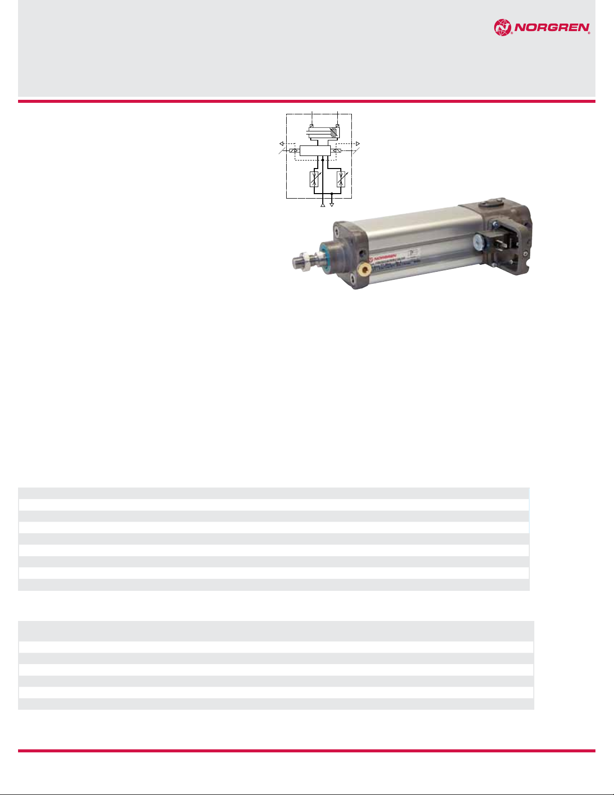
Cylinders and mountings conform to ISO 15552
Complete functional unit
Integrated 5/2 or 5/3 valve
Additional output cylinder ports (2 & 4)
Integrated flow regulator for speed control
PRA/862000/M
IVAC Industrial cylinder
double acting, magnetic piston
Ø 32 ... 100 mm
7
Reed or solid state switches can be mounted
13
flush with the profile barrel
Protection class IP65
Energy efficient
Technical features
Medium:
Compressed air, filtered,
lubricated or non-lubricated
Particles size: Class 7,
ISO 8573 – 1 (dated 2001)
Humidity and water content:
Air supply must be dry.
Corresponding of the application
and working conditions the air
must be dry enough to avoid
condensate. The pressure
dewpoint must be minimum
15° under the application and
working conditions. Oil: Class
4, ISO 8573 – 1 (dated 2001)
Standard:
Based on ISO 15552
(length , mounting pitch and thread
dimensions according to ISO 15552. Some
outside dimensions different to ISO 15552)
Operation:
Double acting, magnetic piston,
adjustable cushioning
Operating pressure:
29 to 116 psig (2 to 8 bar)
Port size:
G1/8, G1/4, G3/8
Cylinder diameters:
32, 40, 50, 63, 80, 100 mm
Standard strokes:
See below
Non-standard strokes:
Available
25 to1000 mm
Operating temperature:
14° to 176°F (-10C to 80°C) max.
Supply voltage:
24 V d.c.
Power consumption:
2 W max
Electrical connection:
DIN EN175301-803, form C
Manual override:
Push and lock
Rating:
100 % continuous duty
Protection class:
IP 65
Technical data
Cylinder Ø (mm) 32 40 50 63 80 100
Air ports
Piston rod Ø (mm)
Piston rod thread
Cushion length inch (mm)
Theoretical thrusts at 87 psig (6 bar) extended lbf. (N)
Theoretical thrusts at 87 psig (6 bar) retracted lbf. (N)
Air consumption at 87 psig (6 bar) extended cu ft/in (l/cm)
Air consumption at 87 psig (6 bar)retracted cu ft/in (l/cm)
G 1/8 G 1/8 G 1/8 G 1/4 G 1/4 G 3/8
12 16 20 20 25 25
M10 x 1.25 M12 x 1.25 M16 x 1.5 M16 x 1.5 M20 x 1.5 M20 x 1.5
0.74" (19) 0.86" (22) 0.94" (24) 0.94" (24) 1.06" (27) 1.34" (34)
108 (482) 170 (754) 265 (1178) 420 (1870) 678 (3016) 1058 (4710)
93 (414) 142 (633) 223 (990) 378 (1680) 612 (2722) 993 (4416)
0.005 (0.056) 0.008 (0.088) 0.012 (0.137 0.019 (0.218) 0.031 (0.350) 0.059 (0.550)
0.004 (0.050) 0.007 (0.076) 0.010 (0.117) 0.018 (0.198) 0.029 (0.324) 0.046 (0.514)
Materials:
Profile barrel:
anodised aluminum,
End covers: pressure diecast
anodised aluminum
Piston rod: stainless steel, see
page 2
Piston rod seals: polyurethane
Piston seals: polyurethane
O-rings: nitrile rubber
Standard strokes
Cylinder
Ø (mm)
32 • • • • • • • • • • •
40 • • • • • • • • • • •
50 • • • • • • • • • • •
63 • • • • • • • • • • •
80 • • • • • • • • • • •
100 • • • • • • • • • • •
4/13
Strokes (mm)
25 50 80 100 125 160 200 250 320 400 500
Our policy is one of continued research and development. We therefore reserve the right to amend,
without notice, the specifications given in this document.
© Norgren Americas 2013
N/us 1.5.250.01
Page 2
PRA/862000/M
24
15
3
V-52-EM-F-spec1
V-52-EMH-F-spec1
24
15
3
V-52-EM-F-spec2
V-52-EMH-F-spec2
24
15
3
V-52B-EM_spec1
V-52B-EMH_spec1
V-53A-EMH-spec1
42
513
V-53A-EM-spec1
V-53E-EMH-spec1
Cylinder variants
Symbol R S C D Model with
magnetic piston
• • • • PRA/862000/M Standard cylinder 4
• • • • PRA/862000/W2 Cylinder with special wiper/
• • • • PRA/862000/MU Cylinder with extended
For the cylinder models style C, D and S see options selector
Option selector
Description Dimensions
Page
seal (suitable for appl. with
4
cement, plaster (stucco),
arizona sand, hoar-frost or
ice)
piston rod
P˙A/862˙˙˙/˙˙˙/213A/˙˙˙˙
Piston rod material Substitute
Stainless steel (martensitic);
Standard wiper seal
Stainless steel (austenitic);
Standard wiper seal
Hard chromium plated;
Standard wiper seal
Stainless steel (austenitic);
hard chromium plated;
Standard wiper seal
Cylinder Ø (mm) Substitute
032, 040, 050, 063, 080, 100
Variants (magnetic piston) Substitute
Standard
Piston rod bellow
Special wiper seal
Extended piston rod
P**/862***/MU/****/***
Extension (mm)
MG
W2
MU
Strokes (mm)
R
1000 max.
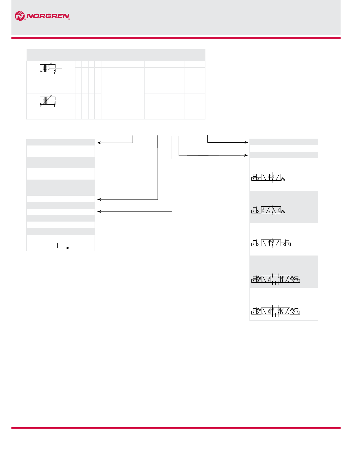
Valve function Substitute
S
C
D
MI
5/2 way solenoid operated,
spring return, cylinder retracted
24
15
3
5/2 way solenoid operated,
spring return, cylinder extended
24
15
3
5/2 way solenoid operated,
solenoid return
42
15
3
5/3 way solenoid operated,
solenoid return, all ports
R
E
B
A
blocked (APB)
42
513
5/3 way solenoid operated,
solenoid return, central open
exhaust (COE)
42
C
4/13
Our policy is one of continued research and development. We therefore reserve the right to amend,
without notice, the specifications given in this document.
© Norgren, Inc. 2013
513
N/us 1.5.250.02
Page 3
PRA/862000/M
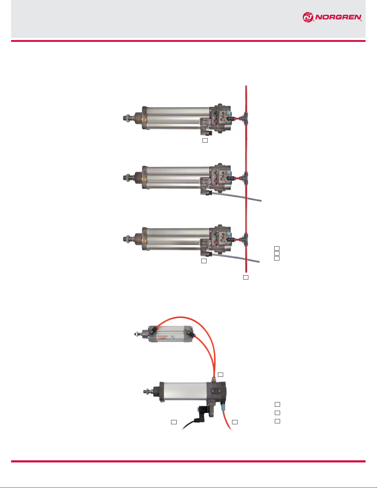
Reduced Installation Time & Cost
To connect the IVAC simply run a single supply line to provide an air supply to each unit. There is no mounting
of valve islands to the machine framework or inside a cabinet and there is no pipework to run around the
machine to connect each valve to each actuator.
4
One of the advantages of the IVAC cylinders is to
use the output cylinder ports (2 & 4) from the main
valve to operate an additional cylinder.
4
Plug
5
Plug with molded cable
6
5
6
3
2
1
Air supply
1
Air supply
2
Electrical connection
3
Output ports (2&4)
4/13
Our policy is one of continued research and development. We therefore reserve the right to amend,
without notice, the specifications given in this document.
© Norgren, Inc. 2013
N/us 1.5.250.03
Page 4
PRA/862000/M
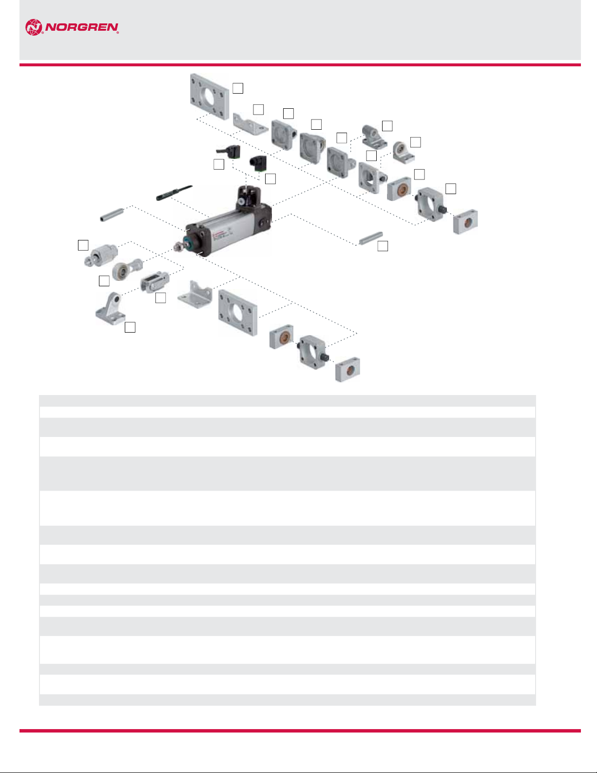
Mountings
1
18
17
16
15
21
2
3
4
5
6
8
7
22
12
9
10
Position Style Standard Corrosion protected
1 B, G Clear anodized aluminum Clear anodised aluminium. Screws: A2
2 C Galvanized steel (ø 32 ... 63 mm)
Painted steel (ø 80 & 100 mm)
3 R Diecast aluminum Black corrosion protected diecast aluminium. Certified
4 UR Galvanized aluminum
Inner ring: steel
Outer ring: brass
5 D Diecast aluminum
Bolt: galvanized steel (martensitic)
Circlip: galvanized steel
6 SW Diecast aluminum Black corrosion protected diecast aluminum
7 US Galvanized aluminium. Inner ring: steel
Outer ring: brass
8 D2 Painted cast iron. Bolt: stainless steel (martensitic)
Circlip: galvanized steel
9 FH Cast iron —
10 A Galvanized steel —
11 Screw — —
12 S Clear anodised aluminum
Bearing: brass
15 F Galvanized steel
Bolt: galvanized steel
Circlip: Galvanized steel
16 SS Painted cast iron —
17 UF Galvanized steel. Inner ring: steel
Outer ring: brass
18 AK Galvanized steel —
—
for the food industry. Screws: A2
Black corrosion protected diecast alumin um
Certified for the food industry
Inner ring: stainless Steel (austenitic)
Outer ring: nickel plated hardened steel
Black corrosion protected diecast aluminum
Certified for the food industry
Bolt: X 10 Cr Ni S 18 9 (1.4305, AISI 303)
Circlip: Stainless steel (martensitic). Screws: A2
Certified for the food industry
—
—
Nickel plated steel
Circlip: X 10 Cr Ni S 18 9 (1.4305, AISI 303)
Bolt: X 10 Cr Ni S 18 9 (1.4305, AISI 303)
Nickel plated steel. Inner ring: stainless steel (austenitic)
Outer ring: nickel plated hardened steel.
4/13
Our policy is one of continued research and development. We therefore reserve the right to amend,
without notice, the specifications given in this document.
© Norgren, Inc. 2013
N/us 1.5.250.04
Page 5
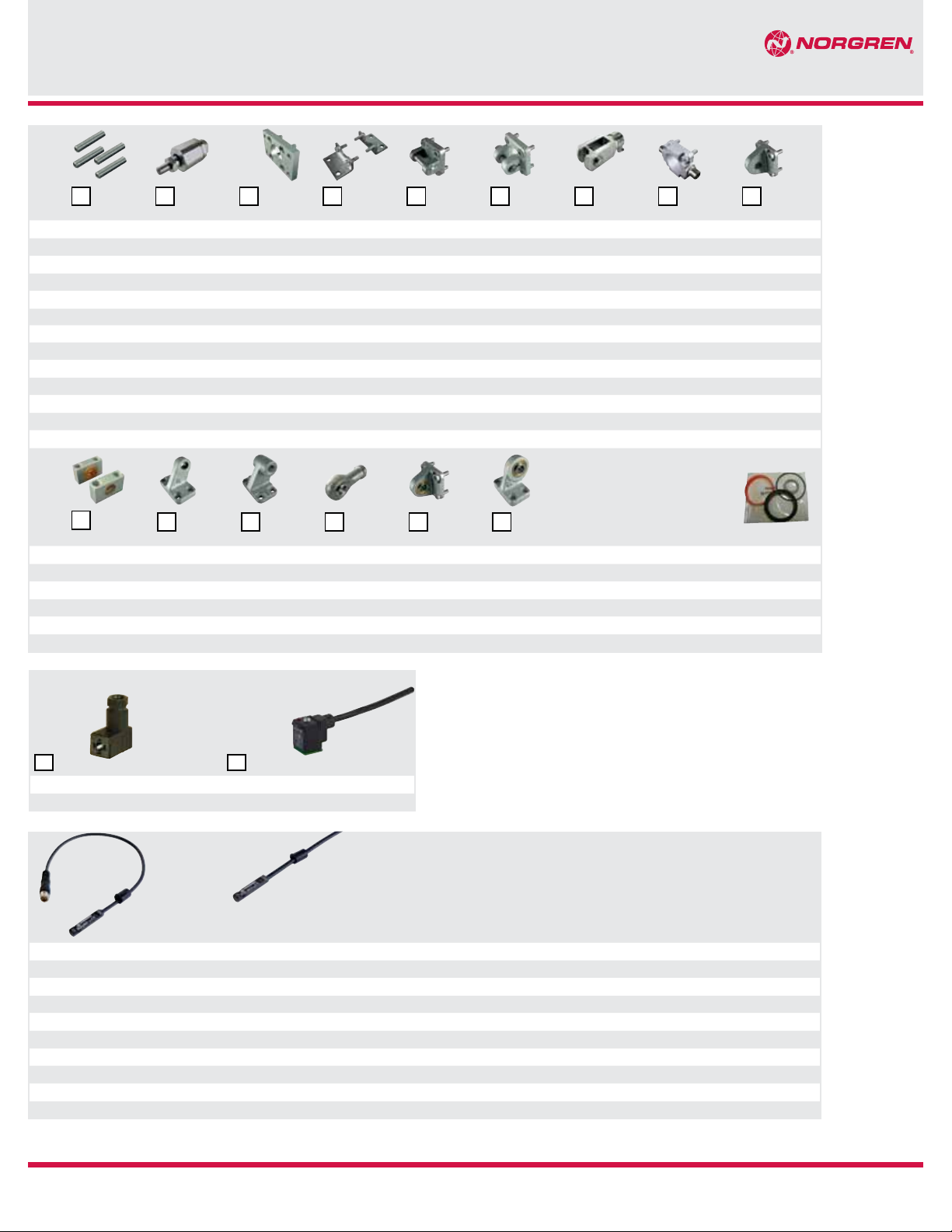
Mountings and service kits
Model ØA
AK
B, G
PRA/862000/M
C
D
D2
F
FH
R
10
Page 7
32 QM/8032/35 QM/8025/38 QA/8032/22 QA/8032/21 QA/8032/23 QA/8032/42 QM/8025/25 QA/8032/34 QA/8032/27
40 QM/8032/35 QM/8040/38 QA/8040/22 QA/8040/21 QA/8040/23 QA/8040/42 QM/8040/25 QA/8040/34 QA/8040/27
50 QM/8050/35 QM/8050/38 QA/8050/22 QA/8050/21 QA/8050/23 QA/8050/42 QM/8050/25 QA/8050/34 QA/8050/27
63 QM/8050/35 QM/8050/38 QA/8063/22 QA/8063/21 QA/8063/23 QA/8063/42 QM/8050/25 QA/8063/34 QA/8063/27
80 QM/8080/35 QM/8080/38 QA/8080/22 QA/8080/21 QA/8080/23 QA/8080/42 QM/8080/25 QA/8080/34 QA/8080/27
100 QM/8080/35 QM/8080/38 QA/8100/22 QA/8100/21 QA/8100/23 QA/8100/42 QM/8080/25 QA/8100/34 QA/8100/27
Corrosion protected mounts
S
Model
12
Ø
32 QA/8032/41 M/P19931 M/P19493 QM/8025/32 QA/8032/33 M/P40310 PRQA/862032/00
40 QA/8040/41 M/P19932 M/P19494 QM/8040/32 QA/8040/33 M/P40311 PRQA/862040/00
50 QA/8040/41 M/P19933 M/P19495 QM/8050/32 QA/8050/33 M/P40312 PRQA/862050/00
63 QA/8063/41 M/P19934 M/P19496 QM/8050/32 QA/8063/33 M/P40313 PRQA/862063/00
80 QA/8063/41 M/P19935 M/P19497 QM/8080/32 QA/8080/33 M/P40314 PRQA/862080/00
100 QA/8100/41 M/P19936 M/P19498 QM/8080/32 QA/8100/33 M/P40315 PRQA/862100/00
Page 10
18
SS
16
Page 7
Page 12
1
Page 8
PVQA/8032/22 PVQA/8032/23 PVQM/8025/25 PVQA/8032/33
PVQA/8040/22 PVQA/8040/23 PVQM/8040/25 PVQA/8040/33
PVQA/8050/22 PVQA/8050/23 PVQM/8050/25 PVQA/8040/33
PVQA/8063/22 PVQA/8063/23 PVQM/8050/25 PVQA/8063/33
PVQA/8080/22 PVQA/8080/23 PVQM/8080/25 PVQA/8080/33
PVQA/8100/22 PVQA/8100/23 PVQM/8080/25 PVQA/8100/33
SW
6
Page 11
2
UF
17
Page 8
Page 10
5
UR
4
Page 9
Page 11
7
US
8
Page 9
Page 12
15
Page 9
9
Page 8
3
Page 10
Service kit
Connectors
Plug with cable gland
Plug with molded cable
22
V10027-D00 V10014-D01 (LED and VDR, cable length 1 m)
V10012-D13 (LED and VDR) V10014-D03 (LED and varistor, cable length 3 m)
21
Magnetically operated switches
Model
Reed *3) Solid state
M/50/LSU/*V – 10 ... 240 10 ... 170 180 -4° to 176° (-20° to 80°) • – 2, 5 or 10 PVC 2 x 0.25 – N/en 4.3.005
M/50/LSU/5U – 10 ... 240 10 ... 170 180 -4° to 176° (-20° to 80°) • – 5 PUR 2 x 0.25 – N/en 4.3.005
TM/50/RAU/2S – 10 ... 240 10 ... 170 180 -4° to 302° (-20° to150°) – – 2 Silicone 2 x 0.25 – N/en 4.3.005
M/50/RAC/5V – 10 ... 240 10 ... 170 180 -4° to 176° (-20° to 80°) – Changeover 5 PVC 3 x 0.25 – N/en 4.3.005
M/50/LSU/CP – 10 ... 60 10 ... 75 180 -4° to 176° (-20° to 80°) • Plug M8x1 5 PVC 3 x 0.25 M/P73001/5 N/en 4.3.005
– M/50/EAP/*V – 10 ... 30 150 -40° to 176° (-40° to 80°) *1) • PNP 2, 5 or 10 PVC 3 x 0.25 – N/en 4.3.007
– M/50/EAP/CP – 10 ... 30 150 -40° to 176° (-40° to 80°) *1) • PNP, Plug M8x1 5 PVC 3 x 0.25 M/P73001/5 N/en 4.3.007
– M/50/EAP/CC – 10 ... 30 150 -40° to 176° (-40° to 80°) *1) • PNP, Plug M12x1 5 PVC 3 x 0.25 M/P34614/5 N/en 4.3.007
– M/50/EAN/*V – 10 ... 30 150 -40° to 176° (-40° to 80°) *1) • NPN 2, 5 or 10 PVC 3 x 0.25 – N/en 4.3.007
– M/50/EAN/CP – 10 ... 30 150 -40° to 176° (-40° to 80°) *1) • NPN, Plug M8x1 5 PVC 3 x 0.25 M/P73001/5 N/en 4.3.007
* Please insert cable length
*1) -40°F to 176°F (-40°C to 80°C) protection class IP65; -4°F to 176°F (-20°C to 80°C) protection class IP67 and IP68, details see data sheet
*2) Supply voltage 24 V d.c. (± 10%) max for P.A/86200/M only *3) For use with 32 mm bore - consult factory.
4/13
Voltage *2)
(V a.c.) (V d.c.)
Our policy is one of continued research and development. We therefore reserve the right to amend,
Current max.
(mA)
Temperature
°F (°C)
without notice, the specifications given in this document.
LED Features Cable length
© Norgren, Inc. 2013
(m)
Cable
type
Cable with
connector
Data sheet
N/us 1.5.250.05
Page 6

PRA/862000/M
ø 32 ... 63
Dimensions Inches (mm)
0.47
(12)
1.16
(29.5)
0.53
(13.5)
G2
2.04 (52)
0.44 (11.3)
0.65 (16.5)
L12
KW
e 11
KK
MM h 9
ø B
KV SW
L2
AM WH
B
ø 32 ... 63 ø 80 & 100
13
14
BG
B
RT
1.89
ø BA e 11
(48)
E4 E3
E2
A
E
RT
A
BH
R
L1
EE
G
8
(26)
1.02
1
0.45
(11.5)
15
4 51 6
ø 80 & 100
PL1
PL2
7
PL
G
9
L8 + #
11
G1
A-A
PL
VA
A-A
A
ø 32 ... 63 ø 80 & 100
13
A
RT
L9
BG
RT
BG
BH
4/13
1
Cushion adjustment front end cover
4
Main valve
5
Pilot block
6
Output ports (2&4)
Our policy is one of continued research and development. We therefore reserve the right to amend,
7
Air supply
8
Exhaust position, do not obstruct
9
Without function - do not use
11
Manual override
without notice, the specifications given in this document.
© Norgren, Inc. 2013
13
Speed control adjustment
14
Cushion adjustment rear end cover
15
M/50 switches can be mounted
flush with the profile
N/us 1.5.250.06
Page 7

PRA/862000/M
Dimensions Inches (mm)
Ø AM Ø B
32 0.87 1.18 1.18 0.63 0.24 1.85 1.08 1.08 1.08 G1/8 0.55 2.32 1.20 M10x1.25 0.20 2.70 0.79 3.70 0.16 0.24
(22.0) (30.0) (30.0) (16.0) (6.0) (47.0) (27.5) (27.5) (27.5) (14.0) (59.0) (30.5) (5.0) (68.5) (20.0) (94.0) (4.0) (6.0)
40 0.94 1.38 1.38 0.63 0.24 2.36 1.36 1.34 1.34 G1/8 0.55 2.32 1.20 M12x1.25 0.24 2.70 0.83 4.13 0.16 0.26
(24.0) (35.0) (35.0) (16.0) (6.0) (60.0) (34.5) (34.0) (34.0) (14.0) (59.0) (30.5) (6.0) (68.5) (21.0) (105.0) (4.0) (6.5)
50 1.26 1.57 1.57 0.63 0.31 2.81 1.57 1.54 1.54 G1/8 0.55 2.48 1.36 M16x1.5 0.31 3.64 1.10 4.17 0.20 0.26
(32.0) (40.0) (40.0) (16.0) (8.0) (71.5) (40.0) (39.0) (39.0) (14.0) (63.0) (34.5) (8.0) (92.5) (28.0) (106.0) (5.0) (6.5)
63 1.26 1.77 1.77 0.63 0.31 3.23 1.81 1.79 1.79 G1/4 0.75 2.60 1.50 M16x1.5 0.31 3.60 1.10 4.76 0.20 0.26
(32.0) (45.0) (45.0) (16.0) (8.0) (82.0) (46.0) (45.5) (45.5) (19.0) (66.0) (38.0) (8.0) (91.5) (28.0) (121.0) (5.0) (6.5)
80 1.57 1.77 1.77 0.67 0.63 3.90 2.13 2.13 2.24 G1/4 0.75 2.93 1.83 M20x1.5 0.39 4.33 1.38 5.04 - 0.30
(40.0) (45.0) (45.0) (17.0) (16.0) (99.0) (54.0) (54.0) (57.0) (19.0) (74.5) (46.5) (10.0) (110.0) (35.0) (128.0) - (7.5)
100 1.57 2.17 2.17 0.67 0.63 4.69 2.56 2.56 2.56 G3/8 0.96 3.19 2.09 M20x1.5 0.39 5.69 1.50 5.43 - 0.39
(40.0) (55.0) (55.0) (17.0) (16.0) (119.0) (65.0) (65.0) (65.0) (24.5) (81.0) (53.0) (10.0) (144.5) (38.0) (138.0) - (10.0)
Ø MM
Ø
h9
32 0.47 0.28 0.39 0.14 1.28 M6 0.12 0.24 1.02 0.00 0.67 0.39 0.20 0.47 1.46 lb. 0.15 lb. PRA/862032/MI+/213A/*
(12.0) (7.0) (10.0) (3.5) (32.5) (3.0) (6.0) (26.0) (0.0) (17.0) (10.0) (5.0) (12.0) (0.66 kg) (0.07 kg)
40 0.63 0.28 0.41 0.16 1.50 M6 0.14 0.24 1.18 0.00 0.75 0.51 0.20 0.47 2.27 lb. 0.24 lb. PRA/862040/MI+/213A/*
(16.0) (7.0) (10.5) (4.0) (38.0) (3.5) (6.0) (30.0) (0.0) (19.0) (13.0) (5.0) (12.0) (1.03 kg) (0.11 kg)
50 0.79 0.28 0.49 0.16 1.83 M8 0.14 0.24 1.46 0.06 0.94 0.67 0.20 0.47 3.48 lb. 0.40 lb. PRA/862050/MI+/213A/*
(20.0) (7.0) (12.5) (4.0) (46.5) (3.5) (6.0) (37.0) (1.5) (24.0) (17.0) (5.0) (12.0) (1.58 kg) (0.18 kg)
63 0.79 0.37 0.57 0.24 2.22 M8 0.16 0.24 1.46 0.00 0.94 0.67 0.24 0.59 5.34 lb. 0.42 lb. PRA/862063/MI+/213A/*
(20.0) (9.5) (14.5) (6.0) (56.5) (4.0) (6.0) (37.0) (0.0) (24.0) (17.0) (6.0) (15.0) (2.42 kg) (0.19 kg)
80 0.98 0.37 0.55 0.24 2.83 M10 0.16 0.24 1.81 0.24 1.18 0.87 0.24 0.59 9.08 lb. 0.64 lb. PRA/862080/MI+/213A/*
(25.0) (9.5) (14.0) (6.0) (72.0) (4.0) (6.0) (46.0) (6.0) (30.0) (22.0) (6.0) (15.0) (4.12 kg) (0.29 kg)
100 0.98 0.47 0.65 0.33 3.50 M10 0.16 0.24 2.01 0.26 1.18 0.87 0.31 0.75 1.46 lb. 0.77lb. PRA/862100/MI+/213A/*
(25.0) (12.0) (16.5) (8.5) (89.0) (4.0) (6.0) (51.0) (6.5) (30.0) (22.0) (8.0) (19.0) (14.0 kg) (0.35 kg)
* Please insert standard stroke length (mm)
+ Please insert valve function
Ø BA
e11
PL PL1 PL2 R RT VA VD WH X1
BG BH E E2 E3 E4 EE G G1 G2 KK KW L1 L2 L8 L9 L12
e11
KV SW 1 2
at 0 mm per 25mmModel
4/13
Our policy is one of continued research and development. We therefore reserve the right to amend,
without notice, the specifications given in this document.
© Norgren, Inc. 2013
N/us 1.5.250.07
Page 8

PRA/862000/M
3
2
4
1
BB
øABøA
P*A/862000/MG*/213A/* Cylinder with piston rod bellow
B
Mountings
Front or rear stud mounting A
Conforms to ISO 15552, type MX1
Cyl.ØØ A Stroke max
per bellow
32 1.57 2.36 1.18 0.98 P#A/862032/MG+/213A/*
(40) (60) (30) (25)
40 2.48 5.71 1.97 1.26 P#A/862040/MG+/213A/*
(63) (145) (50) (32)
50 2.48 5.71 1.57 1.26 P#A/862050/MG+/213A/*
(63) (145) (40) (32)
63 2.48 5.71 1.57 1.26 P#A/862063/MG+/213A/*
(63) (145) (40) (32)
80 3.15 9.84 1.97 1.77 P#A/862080/MG+/213A/*
(80) (250) (50) (45)
100 3.15 9.81 1.97 1.77 P#A/862100/MG+/213A/*
(80) (250) (50) (45)
* Standard stroke length
# Piston rod material
+ Valve function
Piston rod extention B
for first for further
bellow bellows
Model
Piston rod swivel AK
DD
Standard
Ø BB DD TG lb. (kg) Model (A)
32/40 0.67 M6 1.28/1.5 0.04 QM/8032/35
(17.0) (32.5/38) (0.02)
50/63 0.91 M8 1.83/2.22 0.11 QM/8050/35
(23.0) (46.5/56.5) (0.05)
80/100 1.10 M10 2.83/3.5 0.18 QM/8080/35
(28.0) (72/89) (0.08)
4/13
Our policy is one of continued research and development. We therefore reserve the right to amend,
without notice, the specifications given in this document.
TG
TG
© Norgren, Inc. 2013
4∞
KK
4∞
Standard
Ø KK B1 F L L2
32 M10x1.25 0.20 1.02 2.87 0.79 0.75 0.47 0.67 1.18 0.44 QM/8025/38
(5) (26) (73) (20) (19) (12) (17) (30) (0.2)
40 M12x1.25 0.24 1.02 3.03 0.94 0.75 0.47 0.75 1.18 0.44 QM/8040/38
(6) (26) (77) (24) (19) (12) (19) (30) (0.2)
50/63 M16x1.5 0.31 1.34 4.17 1.26 1.18 0.75 0.94 1.65 1.43 QM/8050/38
(8) (34) (106) (32) (30) (19) (24) (42) (0.65)
80/100 M20x1.5 0.39 1.65 4.80 1.57 1.18 0.75 1.18 1.65 1.58 QM/8080/38
(10) (42) (122) (40) (30) (19) (30) (42) (0.72)
L 2
B 1
1
L
2 3 4
KK
F
lb. (kg) Model (AK)
N/us 1.5.250.08
Page 9

PRA/862000/M
UF
L 1
Front flange B, G
Conforms to ISO 15552, type MF1 and MF2
TF
MF
E
R
FB
Standard
Ø E Ø FB MF R TF UF lb. (kg) Model (B, G)
32 1.97 0.28 0.39 1.26 2.52 3.15 0.55 QA/8032/22
(50) (7) (10) (32) (64) (80) (0.25)
40 2.17 0.35 0.39 1.42 2.83 3.54 0.77 QA/8040/22
(55) (9) (10) (36) (72) (90) (0.35)
50 2.56 0.35 0.47 1.77 3.54 4.33 1.54 QA/8050/22
(65) (9) (12) (45) (90) (110) (0.7)
63 2.95 0.35 0.47 1.97 3.94 4.92 1.76 QA/8063/22
(75) (9) (12) (50) (100) (125) (0.8)
80 3.94 0.47 0.63 2.48 4.96 6.06 2.97 QA/8080/22
(100) (12) (16) (63) (126) (154) (1.35)
100 4.72 0.55 0.63 2.95 5.91 7.32 4.84 QA/8100/22
(120) (14) (16) (75) (150) (186) (2.2)
Corrosion protected mounts
32 1.97 0.28 0.39 1.26 2.52 3.15 0.55 PVQA/8032/22
(50) (7) (10) (32) (64) (80) (0.25)
40 2.17 0.35 0.39 1.42 2.83 3.54 0.77 PVQA/8040/22
(55) (9) (10) (36) (72) (90) (0.35)
50 2.56 0.35 0.47 1.77 3.54 4.33 1.54 PVQA/8050/22
(65) (9) (12) (45) (90) (110) (0.7)
63 2.95 0.35 0.47 1.97 3.94 4.92 1.76 PVQA/8063/22
(75) (9) (12) (50) (100) (125) (0.8)
80 3.94 0.47 0.63 2.48 4.96 6.06 2.97 PVQA/8080/22
(100) (12) (16) (63) (126) (154) (1.35)
100 4.72 0.55 0.63 2.95 5.91 7.32 4.84 PVQA/8100/22
(120) (14) (16) (75) (150) (186) (2.2)
Foot mounting C
Conforms to ISO 15552, type MS1
AH
AT
AOAU
Standard
Ø Ø AB AH AO AT AU E TR lb. (kg) Model (C)
32 0.28 1.26 0.31 0.16 0.94 1.89 1.26 0.4 QA/8032/21
(7.0) (32.0) (8.0) (4.0) (24.0) (48.0) (32.0) (0.15)
40 0.39 1.42 0.35 0.16 1.1 2.09 1.42 0.48 QA/8040/21
(10.0) (36.0) (9.0) (4.0) (28.0) (53.0) (36.0) (0.18)
50 0.39 1.77 0.39 0.2 1.26 2.52 1.77 0.8 QA/8050/21
(10.0) (45.0) (10.0) (5.0) (32.0) (64.0) (45.0) (0.3)
63 0.39 1.97 0.47 0.2 1.26 2.91 1.97 1.04 QA/8063/21
(10.0) (50.0) (12.0) (5.0) (32.0) (74.0) (50.0) (0.39)
80 0.47 2.48 0.75 0.2 1.61 3.86 2.48 2.14 QA/8080/21
(12.0) (63.0) (19.0) (5.0) (41.0) (98.0) (63.0) (0.8)
100 0.55 2.8 0.75 0.2 1.61 4.53 2.95 2.55 QA/8100/21
(14.0) (71.0) (19.0) (5.0) (41.0) (115.0) (75.0) (0.95)
Front or rear detachable trunnion FH
Conforms to VDMA 24562 part 2,
type MT 5/6
UW 1
TD e 9
H11
D
TM h14TL
Standard
Ø Ø Dh11 L1 R Ø TD
32 1.18 0.63 0.04 0.47 0.47 1.97 1.77 0.44 QA/8032/34
(30) (16) (1) (12) (12) (50) (45) (0.2)
40 1.38 0.79 0.06 0.63 0.63 2.48 2.17 0.84 QA/8040/34
(35) (20) (1.6) (16) (16) (63) (55) (0.4)
50 1.57 0.94 0.06 0.63 0.63 2.95 2.56 1.32 QA/8050/34
(40) (24) (1.6) (16) (16) (75) (65) (0.6)
63 1.77 0.94 0.06 0.79 0.79 3.54 2.95 2.42 QA/8063/34
(45) (24) (1.6) (20) (20) (90) (75) (1.1)
80 1.77 1.10 0.06 0.79 0.79 4.33 3.94 4.18 QA/8080/34
(45) (28) (1.6) (20) (20) (110) (100) (1.9)
100 2.17 1.50 0.08 0.98 0.98 5.20 4.72 7.70 QA/8100/34
(55) (38) (2) (25) (25) (132) (120) (3.5)
TL TM
e9
UW1 lb. (kg) Model (FH)
h14
ø AB
TR
E
R
4/13
Our policy is one of continued research and development. We therefore reserve the right to amend,
without notice, the specifications given in this document.
© Norgren, Inc. 2013
N/us 1.5.250.09
Page 10

PRA/862000/M
LH
B2
CL
RK
Rear clevis D
Conforms to ISO 15552, type MP2
CB
UB
H 14
FL
L
Standard
H14
Ø CB
32 1.02 0.39 0.87 0.51 2.05 0.35 1.77 0.24 QA/8032/23
40 1.10 0.47 0.98 0.63 2.36 0.47 2.05 0.35 QA/8040/23
50 1.26 0.47 1.06 0.67 2.68 0.47 2.36 0.48 QA/8050/23
63 1.57 0.63 1.26 0.87 3.11 0.59 2.76 0.75 QA/8063/23
80 1.97 0.63 1.42 0.87 3.90 0.59 3.54 1.19 QA/8080/23
100 2.36 0.79 1.61 1.06 4.69 0.79 4.33 1.98 QA/8100/23
Corrosion protected mounts
32 1.02 0.39 0.87 0.51 2.05 0.35 1.77 0.24 PVQA/8032/23
40 1.10 0.47 0.98 0.63 2.36 0.47 2.05 0.35 PVQA/8032/23
50 1.26 0.47 1.06 0.67 2.68 0.47 2.36 0.48 PVQA/8050/23
63 1.57 0.63 1.26 0.87 3.11 0.59 2.76 0.75 PVQA/8063/23
80 1.97 0.63 1.42 0.87 3.90 0.59 3.54 1.19 PVQA/8080/23
100 2.36 0.79 1.61 1.06 4.69 0.79 4.33 1.98 PVQA/8100/23
Ø EK f8FL L LH MR UB lb. (kg) Model (D)
(26) (10) (22) (13) (52) (9) (45) (0.11)
(28) (12) (25) (16) (60) (12) (52) (0.16)
(32) (12) (27) (17) (68) (12) (60) (0.22)
(40) (16) (32) (22) (79) (15) (70) (0.34)
(50) (16) (36) (22) (99) (15) (90) (0.54)
(60) (20) (41) (27) (119) (20) (110) (0.9)
(26) (10) (22) (13) (52) (9) (45) (0.11)
(28) (12) (25) (16) (60) (12) (52) (0.16)
(32) (12) (27) (17) (68) (12) (60) (0.22)
(40) (16) (32) (22) (79) (15) (70) (0.34)
(50) (16) (36) (22) (99) (15) (90) (0.54)
(60) (20) (41) (27) (119) (20) (110) (0.9)
MR
Rear clevis D2
Conforms to ISO 15552, type AB6
H 14
B1
EK f 8
R2
FL
R1
B3
h 9
EK
Standard
H14
Ø B1
32 0.55 1.34 0.13 0.39 0.87 0.43 0.67 0.44 QA/8032/42
40 0.63 1.57 0.17 0.47 0.98 0.47 0.79 0.51 QA/8040/42
50 0.83 1.77 0.17 0.63 1.06 0.57 0.87 0.79 QA/8050/42
63 0.83 2.01 0.17 0.63 1.26 0.71 0.98 1.21 QA/8063/42
80 0.98 2.56 0.17 0.79 1.42 0.87 1.18 1.98 QA/8080/42
100 0.98 2.95 0.17 0.79 1.61 0.87 1.26 3.19 QA/8100/42
B2 B3 Ø EK h9FL R1 R2 lb. (kg) Model (D2)
(14) (34) (3.3) (10) (22) (11) (17) (0.2)
(16) (40) (4.3) (12) (25) (12) (20) (0.23)
(21) (45) (4.3) (16) (27) (14.5) (22) (0.36)
(21) (51) (4.3) (16) (32) (18) (25) (0.55)
(25) (65) (4.3) (20) (36) (22) (30) (0.9)
(25) (75) (4.3) (20) (41) (22) (32) (1.45)
Piston rod clevis F
Conforms to DIN ISO 8140
CE
LE
ER
KK
CL
CM
h11
ø CK
StandardStandard
Ø KK CE Ø CK
32 M10x1.25 1.57 0.39 0.79 0.39 0.63 0.79 1.10 0.20 QM/8025/25
(40) (10) (20) (10) (16) (20) (28) (0.09)
40 M12x1.25 1.89 0.47 0.94 0.47 0.75 0.94 1.26 0.29 QM/8040/25
(48) (12) (24) (12) (19) (24) (32) (0.13)
50/63 M16x1.5 2.52 0.63 1.26 0.63 0.98 1.26 1.63 0.73 QM/8050/25
(64) (16) (32) (16) (25) (32) (41.5) (0.33)
80/100 M20x1.5 3.15 0.79 1.57 0.79 1.26 1.57 1.97 1.47 QM/8080/25
(80) (20) (40) (20) (32) (40) (50) (0.67)
Corrosion protected mounts
32 M10x1.25 1.57 0.39 0.79 0.39 0.63 0.79 1.10 0.20 PVQM/8032/25
(40) (10) (20) (10) (16) (20) (28) (0.09)
40 M12x1.25 1.89 0.47 0.94 0.47 0.75 0.94 1.26 0.29 PVQM/8040/25
(48) (12) (24) (12) (19) (24) (32) (0.13)
50/63 M16x1.5 2.52 0.63 1.26 0.63 0.98 1.26 1.63 0.73 PVQM/8050/25
(64) (16) (32) (16) (25) (32) (41.5) (0.33)
80/100 M20x1.5 3.15 0.79 1.57 0.79 1.26 1.57 1.97 1.47 PVQM/8080/25
(80) (20) (40) (20) (32) (40) (50) (0.67)
CL CM ER LE RK lb. (kg) Model (F)
h11
4/13
Our policy is one of continued research and development. We therefore reserve the right to amend,
without notice, the specifications given in this document.
© Norgren, Inc. 2013
N/us 1.5.250.010
Page 11

PRA/862000/M
FL
ø D 3
Rear eye R
Conforms to ISO 15552, type MP4
EW
L
Standard
Ø Ø CD H9EW FL L MR lb. (kg) Model (R)
32 0.39 1.02 0.87 0.51 0.35 0.20 QA/8032/27
(10) (25.8) (22) (13) (9) (0.09)
40 0.47 1.09 0.98 0.63 0.47 0.24 QA/8040/27
(12) (27.8) (25) (16) (12) (0.11)
50 0.47 1.25 1.06 0.67 0.47 0.37 QA/8050/27
(12) (31.7) (27) (17) (12) (0.17)
63 0.63 1.56 1.26 0.87 0.59 0.53 QA/8063/27
(16) (39.7) (32) (22) (15) (0.24)
80 0.63 1.96 1.42 0.87 0.59 0.81 QA/8080/27
(16) (49.7) (36) (22) (15) (0.37)
100 0.79 2.35 1.61 1.06 0.79 1.30 QA/8100/27
(20) (59.7) (41) (27) (20) (0.59)
Corrosion protected mounts
32 0.39 1.02 0.87 0.51 0.35 0.20 PVQA/8032/27
(10) (25.8) (22) (13) (9) (0.09)
40 0.47 1.09 0.98 0.63 0.47 0.24 PVQA/8040/27
(12) (27.8) (25) (16) (12) (0.11)
50 0.47 1.25 1.06 0.67 0.47 0.37 PVQA/8050/27
(12) (31.7) (27) (17) (12) (0.17)
63 0.63 1.56 1.26 0.87 0.59 0.53 PVQA/8063/27
(16) (39.7) (32) (22) (15) (0.24)
80 0.63 1.96 1.42 0.87 0.59 0.81 PVQA/8080/27
(16) (49.7) (36) (22) (15) (0.37)
100 0.79 2.35 1.61 1.06 0.79 1.30 PVQA/8100/27
(20) (59.7) (41) (27) (20) (0.59)
MR
H 9
CD
Trunnion support S
Conforms to ISO 15552, type AT4
H7
B 1
ø D 2
A
T 1H 2
ø D 1
H 1
F x 45°
C
B 2
Standard
Ø A B1 B2 C Ø
32 1.26 1.81 0.71 0.41 0.47 0.26 0.43 0.04 1.18 0.59 0.27 0.22 QA/8032/41
(32) (46) (18) (10.5) (12) (6.6) (11) (1) (30) (15) (6.8) (0.1)
40/50 1.42 2.17 0.83 0.47 0.63 0.35 0.59 0.06 1.42 0.71 0.35 0.31 QA/8040/41
(36) (55) (21) (12) (16) (9) (15) (1.6) (36) (18) (9) (0.14)
63/80 1.65 2.56 0.91 0.51 0.79 0.43 0.71 0.06 1.57 0.79 0.43 0.40 QA/8063/41
(42) (65) (23) (13) (20) (11) (18) (1.6) (40) (20) (11) (0.18)
100 1.97 2.95 1.12 0.63 0.98 0.55 0.79 0.08 1.97 0.98 0.51 0.75 QA/8100/41
(50) (75) (28.5) (16) (25) (14) (20) (2) (50) (25) (13) (0.34)
D1
H7
ØD1Ø D3F x
45°
H1 H2 T1 lb.
(kg)
Model (S)
Universal piston rod eye UF
Conforms to DIN ISO 8139
CE
ER
H 7
CN
LE AX
KK
EN -0,1
Z
Z
Standard
Ø Thread KKAX CE Ø
32 M10x1.25 0.79 1.69 0.39 0.55 0.55 0.59 0.20 QM/8025/32
(20) (43) (10) (14) (14) (15) 13° (0.09)
40 M12x1.25 0.87 1.97 0.47 0.63 0.63 0.67 0.29 QM/8040/32
(22) (50) (12) (16) (16) (17) 13° (0.13)
50/63 M16x1.5 1.10 2.52 0.63 0.83 0.83 0.87 0.73 QM/8050/32
(28) (64) (16) (21) (21) (22) 15° (0.33)
80/100 M20x1.5 1.30 3.03 0.79 0.98 0.98 1.02 1.47 QM/8080/32
(33) (77) (20) (25) (25) (26) 15° (0.67)
Corrosion protected mounts
32 M10x1.25 0.79 1.69 0.39 0.55 0.55 0.59 0.20 PVQM/8025/32
(20) (43) (10) (14) (14) (15) 13° (0.09)
40 M12x1.25 0.87 1.97 0.47 0.63 0.63 0.67 0.29 PVQM/8040/32
(22) (50) (12) (16) (16) (17) 13° (0.13)
50/63 M16x1.5 1.10 2.52 0.63 0.83 0.83 0.87 0.73 PVQM/8050/32
(28) (64) (16) (21) (21) (22) 15° (0.33)
80/100 M27x2 2.01 4.33 1.18 1.46 1.38 1.42 2.97 PVQM/8080/32
(51) (110) (30) (37) (35) (36) 15° (1.35)
CN
EN
ER LE Z lb. (kg) Model (UF)
H7
-0,1
4/13
Our policy is one of continued research and development. We therefore reserve the right to amend,
without notice, the specifications given in this document.
© Norgren, Inc. 2013
N/us 1.5.250.011
Page 12

PRA/862000/M
EM
L 1
G 1
EN
FL
Wide hinge SW
Conforms to ISO 15552, type AB7
H 9
ø CK
ø D
ø S
K 1
K 2
R
CA
H 2
G 2
G 3
Standard
Ø CA Ø
CK
32 1.26 0.39 0.43 0.28 1.00 0.83 0.71 1.22 1.50 1.97 0.06 0.39 0.26 0.11 M/P19493
(32) (10) (11) (7) (25.5) (21) (18) (31) (38) (50) (1.6) (10) (6.6) (0.05)
40 1.42 0.47 0.43 0.35 1.08 0.94 0.87 1.38 1.61 2.13 0.06 0.43 0.26 0.15 M/P19494
(36) (12) (11) (9) (27.5) (24) (22) (35) (41) (54) (1.6) (11) (6.6) (0.07)
50 1.77 0.47 0.59 0.43 1.24 1.30 1.18 1.77 1.97 2.56 0.06 0.51 0.35 0.31 M/P19495
(45) (12) (15) (11) (31.5) (33) (30) (45) (50) (65) (1.6) (13) (9) (0.14)
63 1.97 0.63 0.59 0.47 1.56 1.46 1.38 1.97 2.05 2.64 0.06 0.59 0.35 0.40 M/P19496
(50) (16) (15) (12) (39.5) (37) (35) (50) (52) (67) (1.6) (15) (9) (0.18)
80 2.48 0.63 0.71 0.55 1.95 1.85 1.57 2.36 2.60 3.31 0.10 0.59 0.43 0.62 M/P19497
(63) (16) (18) (14) (49.5) (47) (40) (60) (66) (84) (2.5) (15) (11) (0.28)
100 2.80 0.79 0.71 0.59 2.34 2.17 1.97 2.76 2.99 3.70 0.10 0.75 0.43 0.92 M/P19498
(71) (20) (18) (15) (59.5) (55) (50) (70) (76) (94) (2.5) (19) (11) (0.42)
Corrosion protected mounts
32 1.26 0.39 0.43 0.31 1.04 0.83 0.71 1.22 1.50 2.01 0.06 0.39 0.26 0.11 M/P40459
(32) (10) (11) (8) (26.5) (21) (18) (31) (38) (51) (1.6) (10) (6.6) (0.05)
40 1.42 0.47 0.43 0.39 1.12 0.94 0.87 1.38 1.61 2.13 0.06 0.43 0.26 0.15 M/P40460
(36) (12) (11) (10) (28.5) (24) (22) (35) (41) (54) (1.6) (11) (6.6) (0.07)
50 1.77 0.47 0.59 0.47 1.28 1.30 1.18 1.77 1.97 2.56 0.06 0.51 0.35 0.31 M/P40461
(45) (12) (15) (12) (32.5) (33) (30) (45) (50) (65) (1.6) (13) (9) (0.14)
63 1.97 0.63 0.59 0.47 1.59 1.46 1.38 1.97 2.05 2.64 0.06 0.59 0.35 0.40 M/P40462
(50) (16) (15) (12) (40.5) (37) (35) (50) (52) (67) (1.6) (15) (9) (0.18)
80 2.48 0.63 0.71 0.55 1.99 1.85 1.57 2.36 2.60 3.39 0.10 0.59 0.43 0.62 M/P40463
(63) (16) (18) (14) (50.5) (47) (40) (60) (66) (86) (2.5) (15) (11) (0.28)
100 2.80 0.79 0.71 0.59 2.38 2.17 1.97 2.76 2.99 3.78 0.10 0.75 0.43 0.92 M/P40464
(71) (20) (18) (15) (60.5) (55) (50) (70) (76) (96) (2.5) (19) (11) (0.42)
H2 EM G1 G2 G3 K1 K2 L1 R Ø Slb.
H9
Ø D
(kg)
Model
(SW)
Universal rear eye UR
Conforms to ISO 15552, type MP6
Z
Z
R
Standard
Ø Ø CN H7EN ER FL R Z lb. (kg) Model (UR)
32 0.39 0.55 0.63 0.87 0.57 0.33 QA/8032/33
(10) (14) (16) (22) (14.5) 13° (0.15)
40 0.47 0.63 0.71 0.98 0.71 0.55 QA/8040/33
(12) (16) (18) (25) (18) 13° (0.25)
50 0.63 0.83 0.83 1.06 0.75 0.88 QA/8050/33
(16) (21) (21) (27) (19) 15° (0.4)
63 0.63 0.83 0.91 1.26 0.94 1.21 QA/8063/33
(16) (21) (23) (32) (24) 15° (0.55)
80 0.79 0.98 1.10 1.42 0.94 1.98 QA/8080/33
(20) (25) (28) (36) (24) 15° (0.9)
100 0.79 0.98 1.18 1.61 1.14 3.30 QA/8100/33
(20) (25) (30) (41) (29) 15° (1.5)
Corrosion protected mounts
32 0.39 0.55 0.63 0.87 0.57 0.33 PVQA/8032/33
(10) (14) (16) (22) (14.5) 13° (0.15)
40 0.47 0.63 0.75 0.98 0.71 0.55 PVQA/8040/33
(12) (16) (19) (25) (18) 13° (0.25)
50 0.63 0.83 0.83 1.06 0.75 0.88 PVQA/8050/33
(16) (21) (21) (27) (19) 13° (0.4)
63 0.63 0.83 0.94 1.26 0.94 1.21 PVQA/8063/33
(16) (21) (24) (32) (24) 15° (0.55)
80 0.79 0.98 1.10 1.42 0.94 1.98 PVQA/8080/33
(20) (25) (28) (36) (24) 15° (0.9)
100 0.79 0.98 1.18 1.61 1.14 3.30 PVQA/8100/33
(20) (25) (30) (41) (29) 15° (1.5)
H 7
CN
ER
4/13
Our policy is one of continued research and development. We therefore reserve the right to amend,
without notice, the specifications given in this document.
© Norgren, Inc. 2013
N/us 1.5.250.012
Page 13

Narrow hinge SS
L 1
EN
PRA/862000/M
EM
G 7
ø CN
ø D
L 1
ø S
K 1
K 2
R
CA
H 2
G 1
G 2
G 3
Standard
Ø CA Ø
32 1.26 0.39 0.43 0.31 0.39 0.83 0.71 1.22 1.50 2.01 0.06 0.39 0.26 0.33 M/P19931
(32) (10) (11) (8) (10) (21) (18) (31) (38) (51) (1.6) (10) (6.6) (0.15)
40 1.42 0.47 0.43 0.39 0.47 0.94 0.87 1.38 1.61 2.13 0.06 0.43 0.26 0.44 M/P19932
(36) (12) (11) (10) (12) (24) (22) (35) (41) (54) (1.6) (11) (6.6) (0.2)
50 1.77 0.63 0.59 0.47 0.63 1.30 1.18 1.77 1.97 2.56 0.06 0.51 0.35 1.06 M/P19933
(45) (16) (15) (12) (16) (33) (30) (45) (50) (65) (1.6) (13) (9) (0.48)
63 1.97 0.63 0.59 0.47 0.63 1.46 1.38 1.97 2.05 2.64 0.06 0.59 0.35 1.10 M/P19934
(50) (16) (15) (12) (16) (37) (35) (50) (52) (67) (1.6) (15) (9) (0.5)
80 2.48 0.79 0.71 0.55 0.79 1.85 1.57 2.36 2.60 3.39 0.10 0.59 0.43 1.65 M/P19935
(63) (20) (18) (14) (20) (47) (40) (60) (66) (86) (2.5) (15) (11) (0.75)
100 2.80 0.79 0.71 0.59 0.79 2.17 1.97 2.76 2.99 3.78 0.10 0.75 0.43 2.64 M/P19936
(71) (20) (18) (15) (20) (55) (50) (70) (76) (96) (2.5) (19) (11) (1.2)
Ø DH2 EM G1 G2 G3 K1 K2 L1 R ØSlb.
G7
CN
(kg)
Model
(SS)
Swivel hinge US
Conforms to VDMA 24562 part 2
-0,1
G 1
G 2
G 3
ø D
H 7
ø CN
EU
ER
Z
Z
CH
H 2
ø S
K 1
K 2
Standard
Ø CH Ø
32 1.26 0.39 0.43 0.55 0.63 0.41 0.83 0.71 1.22 0.39 1.50 2.01 0.06 0.26 0.42 M/P40310
(32) (10) (11) (14) (16) (10.5) (21) (18) (31) (10) (38) (51) (1.6) (6.6) 13° (0.19)
40 1.42 0.47 0.43 0.63 0.71 0.47 0.94 0.87 1.38 0.39 1.61 2.13 0.06 0.26 0.53 M/P40311
(36) (12) (11) (16) (18) (12) (24) (22) (35) (10) (41) (54) (1.6) (6.6) 13° (0.24)
50 1.77 0.63 0.59 0.83 0.83 0.59 1.30 1.18 1.77 0.47 1.97 2.56 0.06 0.35 1.01 M/P40312
(45) (16) (15) (21) (21) (15) (33) (30) (45) (12) (50) (65) (1.6) (9) 13° (0.46)
63 1.97 0.63 0.59 0.83 0.91 0.59 1.46 1.38 1.97 0.47 2.05 2.64 0.06 0.35 1.30 M/P40313
(50) (16) (15) (21) (23) (15) (37) (35) (50) (12) (52) (67) (1.6) (9) 15° (0.59)
80 2.48 0.79 0.71 0.98 1.10 0.71 1.85 1.57 2.36 0.55 2.60 3.39 0.10 0.43 2.27 M/P40314
(63) (20) (18) (25) (28) (18) (47) (40) (60) (14) (66) (86) (2.5) (11) 15° (1.03)
100 2.80 0.79 0.71 0.98 1.18 0.71 2.17 1.97 2.76 0.59 2.99 3.78 0.10 0.43 3.08 M/P40315
(71) (20) (18) (25) (30) (18) (55) (50) (70) (15) (76) (96) (2.5) (11) 15° (1.4)
4/13
CN
H7
ØDEN
-0,1
ER EU G1 G2 G3 H2 K1 K2 L1 Ø SZ lb. (kg) Model (US)
Our policy is one of continued research and development. We therefore reserve the right to amend,
without notice, the specifications given in this document.
© Norgren, Inc. 2013
N/us 1.5.250.013
Page 14

PRA/862000/M
Warning
These products are intended for use in industrial compressed air
systems only. Do not use these products where pressures and
temperatures can exceed those listed under »Technical features«.
Before using these products with fluids other than those specified,
for non-industrial applications, life-support systems, or other applications not within published specifications, consult NORGREN.
Through misuse, age, or malfunction, components used in
fluid power systems can fail in various modes.
Our policy is one of continued research and development. We therefore reserve the right to amend,
4/13
without notice, the specifications given in this document.
see engineering advantage
Scan with a QR code read er – w ww.nor gren.com /us/iv ac
The system designer is warned to consider the failure modes
of all component parts used in fluid power systems and to provide
adequate safeguards to prevent personal injury or damage to
equipment in the event of such failure.
System designers must provide a warning to end users in
the system instructional manual if protection against
a failure mode cannot be adequately provided.
System designers and end users are cautioned to review specific
warnings found in instruction sheets packed and shipped with
these products.
© Norgren, Inc. 2013
N/us 1.5.250.014
 Loading...