

Page 1
05/05
N/UK 8.240.630.01
P64S, P74S
Our policy is one of continuous research and development.
We reserve the right to amend, without notice, the specifications given in this document.
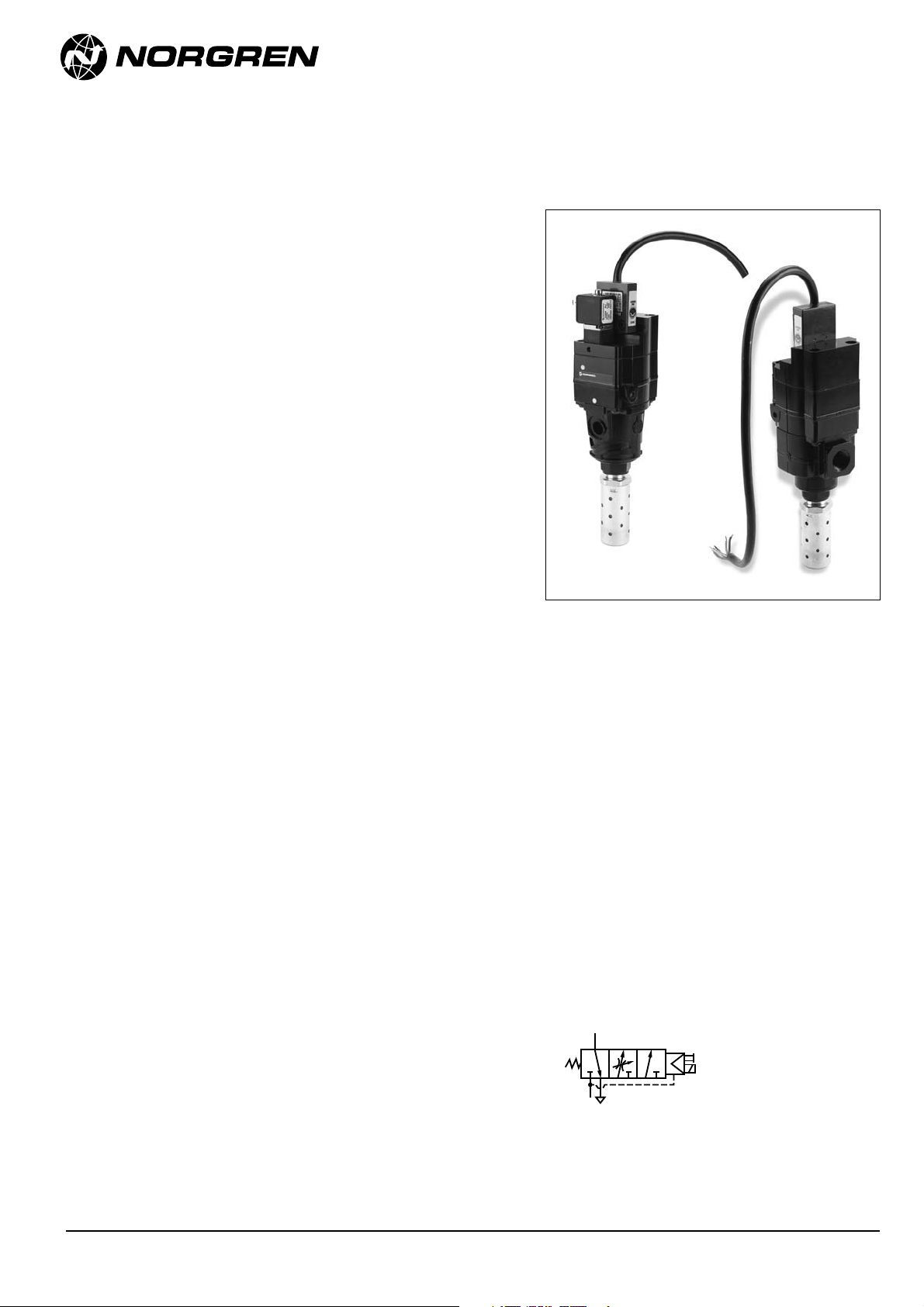
Olympian Plus and Excelon
Soft Start Monitored Dump Valve
Olympian Plus plug in design or
EXCELON inline / modular installation
Controlled increase of downstream
pressure on start up
Monitored dump function
High forward flow capacity
High flow dump facility
Materials:
Body: zinc alloy
Intermediate body: aluminium
Elastomers: synthetic materials
Filter discs: sintered plastic
Internal components: brass / steel /
stainless steel
Top plate: aluminium
Exhaust Bonnet: zinc alloy
Yoke (P64S only): zinc alloy
Ordering Information
See
Ordering Information
on the following
pages.
ISO Symbol
Solenoid operated
Technical Data
Fluid: Compressed air
Maximum Pressure: 16 bar (240 psig)
Minimum Operating Pressure: 3 bar (45 psig)
Operating Temperature: -20°C to 50°C
(Solenoid rating max is 50°C whilst unit max is 80°C. Consult our technical service
below +2°C)
Gauge Ports: Rc1/8
Exhaust Ports: ISO G1/2 with ISO G and Rc main ports,
1/2“ PTF with PTF main ports
Typical flow with 6,3 bar (90psig) inlet pressure and
outlet pressure drop of 0,5 var (7 psig)
57dm
3
/s (120 scfm) (P1 to P2 = Cv 4.2) (P2 to P3 Cv = 5.6)
Snap pressure: Full flow when downstream pressure reaches
35% - 60% of inlet pressure
Charge time: For 2 litre downstream volume and inlet pressure of
6,3 bar (90 psig), 0,2s minimum, 75 secs. maximum
Solenoid operator
22 mm, 24V DC, 2W only (no manual overide)
Soft start valves allow a controlled increase of
pressure onto downstream cylinders / machines
offering protection to personnel equipment.
The positively driven micro switch ensures a
monitored dump function.
Note: Turn on system air supply prior to applying
signal to operator. Failure to do so may cause valve to
continuously exhaust.
Page 2
N/UK 8.240.630.02
05/05
P64S, P74S
Our policy is one of continuous research and development.
We reserve the right to amend, without notice, the specifications given in this document.
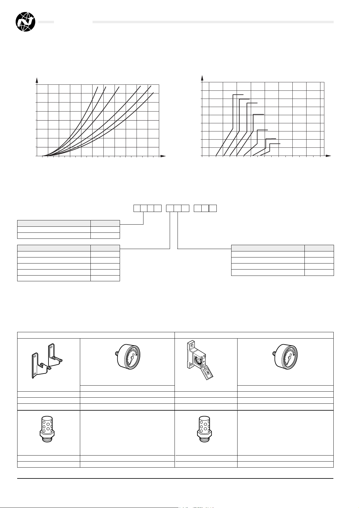
Type Substitute
Olympian Plus 6
Excelon 7
Port Size Substitute
1/4" 2
3/8" 3
1/2" 4
3/4" 6
No Yoke (P64S only) N
Typical Performance Characteristics
P4-S
-
1C N N
** to order air pilot models also substitute ‘NNN’
at digits 8, 9 and 10 e.g. P64F-2GA-NNN.
Thread Type Substitute
PTF A
ISO Rc Parallel B
ISO G Parallel G
No Yoke (P64S only) N
Accessories
Ordering Information
P74S
Wall Mounting
Ø 50 mm Pressure Gauge
Bracket Kit R1/8 1/8″ PTF
4314-52 4 bar (60 psig): 18-013-012 18-013-202
10 bar (150 psig): 18-013-013 18-013-204
25 bar (360 psig): 18-013-014 18-013-206
Silencer
MB004B (R1/2)
MB004A
P64S
Wall Mounting
Ø 50 mm Pressure Gauge
Bracket Kit R1/8 1/8″ PTF
74504-50 4 bar (60 psig): 18-013-012 18-013-202
10 bar (150 psig): 18-013-013 18-013-204
25 bar (360 psig): 18-013-014 18-013-206
Silencer
MB004B (R1/2)
MB004A
PRESSURE DROP (bar g)
OUTLET PRESSURE (bar g)
MAXIMUM CHARGE TIME
FLOW CHARACTERISTICS
AIR FLOW (dm3/s)
CHARGE TIME (s)
INLET PRESSURE (bar g)
(bar) (bar)
0,8
0,7
0,6
0,5
0,4
0,3
0,2
0,1
0
0
10 20 30 40 50 60 70 80 90 100
2 4 6,3 10 12
(bar)
18
14
3
/s)
(dm
16
14
12
10
8
6
4
2
0
0 5 10 15 20 25 30 35 40
(s)
Page 3

06/05
P64S, P74S
Our policy is one of continuous research and development.
We reserve the right to amend, without notice, the specifications given in this document.
N/AL.8.1.PXS.03
Dimensions mm (inches)
P74S
76,5
201,5
G 1/2
73
12
168,5
30
84
204
170,5 G 1/2
73
2
30
1
Page 4

N/AL.8.1.PXS.04 06/05
Warning
These products are intended for use in industrial compressed air
systems only. Do not use these products where pressures and
temperatures can exceed those listed under ‘Technical Data’.
Before using these products with fluids other than those specified, for
non-industrial applications, life-support systems, or other applications not
within published specifications, consult NORGREN.
Through misuse, age, or malfunction, components used in fluid
power systems can fail in various modes. The system designer is warned
to consider the failure modes of all component parts used in fluid power
systems and to provide adequate safeguards to prevent personal injury or
damage to equipment in the event of such failure.
System designers must provide a warning to end users in the
system instructional manual if protection against a failure mode
cannot be adequately provided.
System designers and end users are cautioned to review specific
warnings found in instruction sheets packed and shipped with these
products.
Water vapor will pass through these units and will condense into
liquid if air temperature drops in the downstream system. Install an air
dryer if water condensation could have a detrimental effect on the
application.
P64S, P74S
Our policy is one of continuous research and development.
We reserve the right to amend, without notice, the specifications given in this document.
Pilz relay
To assist in compliance with the Machinery Directive 89/392/EEC a Pilz
circuit should be used. This requires 2 units.
Switch Details
All electrical connections to be made by a competent licensed electrician
Break - before – Make contact
1 Normally Open / 1 Normally Closed
blue
black
E-stop
StartPliz relay
brown
green/yellow
Soft Start
Monitored dump valves
black
blue
Zb
black black
O.P. 1
O.P. 2
brown
green/yellow
24V
E-stop
24V
2
2
3 213 2
0V
P P
1
1
2
2
2
31
3
Soft Start
Monitored dump valves
V1 V2
3
1
3
212 10
1
212 10
StartPilz relay
0V
V1
V2 V3 V3
 Loading...