

Page 1
Brookville, OH USA Phone 937-833-4033 www.norgren.com
ACT-1-1
Section 1
NFPA Aluminum & Steel Cylinders
Page ACT-1-18
Cylinder with
01 (MS4)
Side Tapped
Page ACT-1-22
Cylinder with
03 (MF1) Head
Rectangular Flange
Page ACT-1-24
Cylinder with
03 (ME3) Head
Square Flange
Page ACT-1-24
Cylinder with
04 (ME4) Cap
Square Flange
Page ACT-1-28
Cylinder with
05 (MX0) Basic
Page ACT-1-36
Cylinder with
07 (MT1)
Head Trunnion
Page ACT-1-40
Cylinder with
08 (MT2)
Cap Trunnion
Page ACT-1-26
Cylinder with
04 (MF2) Cap
Rectangular Flange
Page ACT-1-32
Cylinder with
06 (MX1) Tie Rod-4,
6C (MX2) Cap, 6R (MX3)
Head, 6B (MX4) Tie Rod-2
Page ACT-1-44
Cylinder with
09 (MS2)
Side Lugs
Page ACT-1-48
Cylinder with
10 (MT4) Intermediate
Center Trunnion
Page ACT-1-52
Cylinder with
11 (MS1)
Side End Angles
Page ACT-1-56
Cylinder with
12 (MP1) Cap
Fixed Clevis
Page ACT-1-60
Cylinder with
15 (MS7)
Side End Lugs
Page ACT-1-62
Cylinder with 16
Sleeve Nut Construction
Side Tapped (Universal)
Page ACT-1-70
Cylinder with
32 (MP3) Cap
Fixed Eye
Page ACT-1-78
Cylinder with 60 Base Bar
(A & EA Only)
Page ACT-1-74
Cylinder with
42 (MP4) Detachable
Cap Eye
Page ACT-1-80
Double Rod End Cylinders
Page ACT-1-76
Cylinder with
52 Spherical Bearing
Page ACT-1-64
Cylinder with
20 (MF5) Head
Square Flange
Page ACT-1-66
Cylinder with
21 (MF6) Cap
Square Flange
Page ACT-1-68
Cylinder with
22 (MP2) Detachable
Clevis
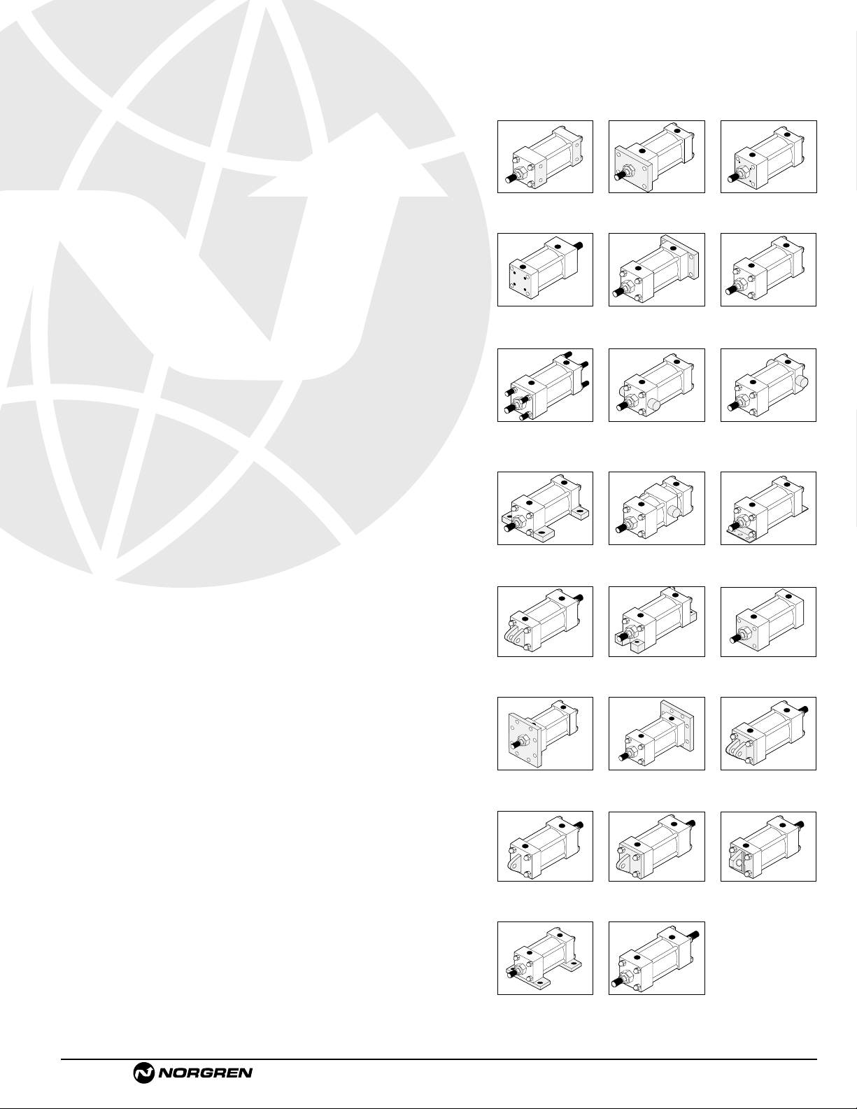
Series “A” Aluminum (1-1/2" to 8") &
Series “J” Steel (1-1/2"to 12") Bore Cylinder Features
Series “A” and “J” Technical Features . . . . . . . . . . . . . . . . ACT-1-2, ACT-1-6
Series “EA” Aluminum (1-1/2" to 8") &
Series “EJ” Steel (1-1/2"to 12") Bore Cylinder Features
Series “EA” and “EJ” Impact Dampening Seals . . . . ACT-1-4, ACT-1-8, ACT-1-12
Series “EA” and “EJ” Technical Features . . . . . . . . . . . . . . ACT-1-5, ACT-1-9
Decel Cushioned Cylinder . . . . . . . . . . . . . . . . . . . . . . . . . . . . . . . . ACT-1-10
General Technical Information . . . . . . . . . . . . . . . . . . . . . . . . . . . . . ACT-1-13
Code NFPA Bore Sizes Description
01 MS4 1-1/2" – 12" Side Tapped . . . . . . . . . . . . . . . . . . . . . ACT-1-18
03 MF1 1-1/2" – 6" Head Rectangular Flange . . . . . . . . . . . . ACT-1-22
03 ME3 7" – 12" Head Square Flange . . . . . . . . . . . . . . . . ACT-1-24
04 ME4 7" – 12" Cap Square Flange . . . . . . . . . . . . . . . . ACT-1-24
04 MF2 1-1/2" – 6" Cap Rectangular Flange . . . . . . . . . . . . . ACT-1-26
05 MX0 1-1/2" – 12" Basic . . . . . . . . . . . . . . . . . . . . . . . . . . . ACT-1-28
06 MX1 1-1/2" – 12" 4 Tie Rods Both Ends . . . . . . . . . . . . . . ACT-1-32
6C MX2 1-1/2" – 12" Cap Tie Rods . . . . . . . . . . . . . . . . . . . . . ACT-1-32
6R MX3 1-1/2" – 12" Head Tie Rods . . . . . . . . . . . . . . . . . . . . ACT-1-32
6B MX4 1-1/2" – 12" 2 Tie Rods Both Ends . . . . . . . . . . . . . . ACT-1-32
7R MT1 1-1/2" – 8" Removable Head Trunnion
(A & EA Only) . . . . ACT-1-36
07 MT1 1-1/2" – 12 Head Trunnion (J & EJ Only) . . . . . . . . . . . ACT-1-36
8R MT2 1-1/2" – 8" Removable Cap Trunnion . . . . . . . . . . . . ACT-1-40
08 MT2 1-1/2" – 12 Cap Trunnion . . . . . . . . . . . . . . . . . . . . . ACT-1-40
09 MS2 1-1/2" – 12" Side Lugs . . . . . . . . . . . . . . . . . . . . . . . ACT-1-44
10 MT4 1-1/2" – 12" Intermediate Center Trunnion . . . . . . . . . ACT-1-48
11 MS1 1-1/2" – 12" Side End Angles . . . . . . . . . . . . . . . . . . . ACT-1-52
12 MP1 1-1/2" – 12" Cap Fixed Clevis . . . . . . . . . . . . . . . . . . ACT-1-56
15 MS7 1-1/2" – 8" Side End Lugs . . . . . . . . . . . . . . . . . . . . ACT-1-60
16 N/A 1-1/2" – 6" SleeveNut Construction Universal . . . . . . ACT-1-62
20 MF5 1-1/2" – 6" Head Square Flange . . . . . . . . . . . . . . . . ACT-1-64
21 MF6 1-1/2" – 6" Cap Square Flange . . . . . . . . . . . . . . . . ACT-1-66
22 MP2 1-1/2" – 8" Detachable Cap Clevis . . . . . . . . . . . . . . ACT-1-68
32 MP3 1-1/2" – 12" Cap Fixed Eye . . . . . . . . . . . . . . . . . . . . ACT-1-70
42 MP4 1-1/2" – 8" Detachable Cap Eye . . . . . . . . . . . . . . . . ACT-1-74
52 N/A 1-1/2" – 8" Spherical Bearing . . . . . . . . . . . . . . . . . . ACT-1-76
60 N/A 1-1/2" – 6" Base Bar (A & EA) . . . . . . . . . . . . . . . . . ACT-1-78
Series DA & EDA (Aluminum) and
DJ & EDJ (Steel) Double Rod End Cylinders . . . . . . . . . . . . . . . . . . . ACT-1-80
Series A & EA (1-1/2" to 8") and
Series J & EJ (1-1/2" to12") Cylinder Accessories . . . . . . . . . . . . . . . ACT-1-84
Series A & EA and J & EJ Optional Features & Custom Cylinders . . . . ACT-1-86
Stroke Signal Valve/Pneulectric Valve . . . . . . . . . . . . . . . . . . . . . . . . . ACT-1-88
Reed & Solid State Switch Information . . . . . . . . . . . . . . . . . . . . . . . . ACT-1-90
Flow Controls . . . . . . . . . . . . . . . . . . . . . . . . . . . . . . . . . . . . . . . . . . ACT-1-92
Rod Alignment Coupler . . . . . . . . . . . . . . . . . . . . . . . . . . . . . . . . . . . ACT-1-94
Air-Oil Tank . . . . . . . . . . . . . . . . . . . . . . . . . . . . . . . . . . . . . . . . . . . ACT-1-94
Series A & EA and J & EJ Standard and Special Options . . . . . . . . . . ACT-1-95
Series A & EA (1-1/2" - 8") and Series J & EJ (1-1/2" - 12")
Order Information . . . . . . . . . . . . . . . . . . . . . . . . . . . . . . . . . . . . . . ACT-1-96
Seal Replacement Kits for Series A, EA, J & EJ . . . . . . . . . . . . . . . . . ACT-1-97
NFPA - National Fluid Power Association
Page 2
ACT-1-2
Brookville, OH USA Phone 937-833-4033 www.norgren.com
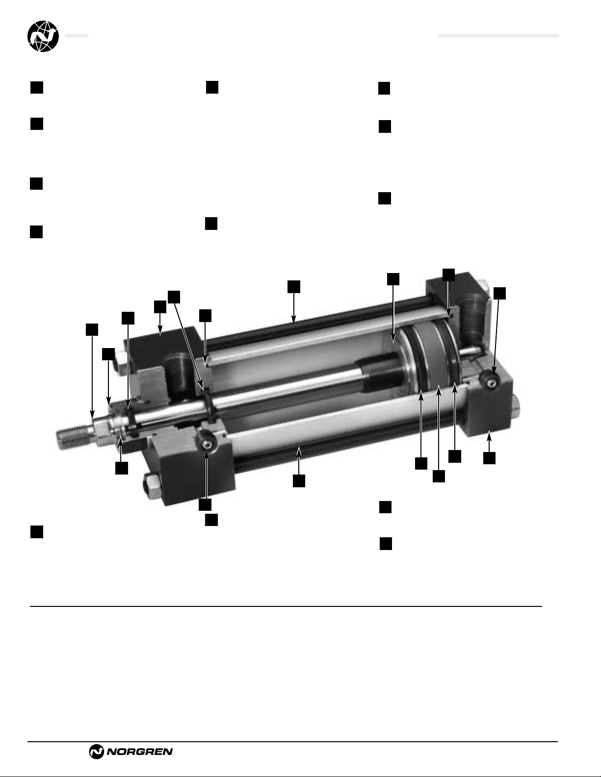
Series A, NFPA Aluminum Air Cylinders (ø1-1/2" to 8"), Cylinder Features
Ultra Cushion®Seals: Advanced
design features a unique, one-piece,
compound seal of nitrile* captured within
a precision machined groove. Linear and
radial “float” of the cushion seals
eliminates misalignment. Ultra Cushions
provide exceptionally fast “out of
cushion” stroke reversal. (Head and Cap
Cushions are optional.)
*Nitrile seals on the 5/8
" & 1" rod diameter.
For rod sizes 1-
3/8"
and larger, urethane seals are standard.
O-Ring Tube Seal: Buna is
standard. (Viton is optional.)
Cylinder Tube: High-strength
aluminum alloy ideally suited for air
service. The tube is clear anodized on the
O.D. and hard anodic coated on the I.D.,
resulting in a smooth, file hard (60RC),
corrosion and score resistant
surface finish.
Tie Rods: High-strength steel maintains
uniform compression on tube end seals.
Piston: Machined solid aluminum
alloy, light-weight for low inertia, yet
strong. Threaded piston is installed with
high strength threadlocker adhesive then
staked to the piston rod.
Adjustable Captive Cushion
Needle:
A one-piece, precision threaded
brass cushion adjustment screw with a
threaded steel capture ring. It provides
safe and precise cushion adjustment.
6
Piston Seals: Long-wearing
nitrile seals.
Wear Ring: Reinforced Teflon
®
compounded with polyphenylene sulfide
provides supreme wear and excellent
bearing support.
Standard non-cushioned Series A cylinders are
recommended for applications that require full
bottoming of the piston and where the noise
emitted by the metal-to-metal impact between the
piston and cylinder end caps is tolerable. We
recommend that optional non-adjustable cushions
be added for piston speeds (moving light tools)
ranging from 15 to 30 in/sec. For speeds exceeding
30 in/sec, the cylinders should be equipped with
adjustable air cushions.
11
12
13
Piston Rod: Hard chrome plated
high-tensile steel, ground and polished.
Rod Bearing: External removable
threaded steel bearing housing (black
oxide finish), with an oil-impregnated
sintered iron rod bearing.
Rod Seal: Nitrile lip-type seal
is pressure energized and wear
compensating for durability and long life.
Head/Cap: Precision machined from
alloy aluminum, then anodized for
corrosion resistance (black finish).
1
2
3
5
Wiper Seal: Lip-type urethane
wiper seal keeps contaminates
from getting into cylinder by
aggressively wiping foreign materials
from the piston rod, enhancing the
rod seal life.
Application Information
Series A NFPA interchangeable aluminum air
cylinders are offered with a variety of accessories,
standard and optional equipment to meet your
application needs.
7
8
9
The addition of a Teflon®wear ring to the
outer perimeter of the piston permits us to
guarantee its operation against failure due
to lack of lubrication for ONE FULL YEAR,
regardless of cycles! See page ACT-1-98 for
complete warranty.
4
10
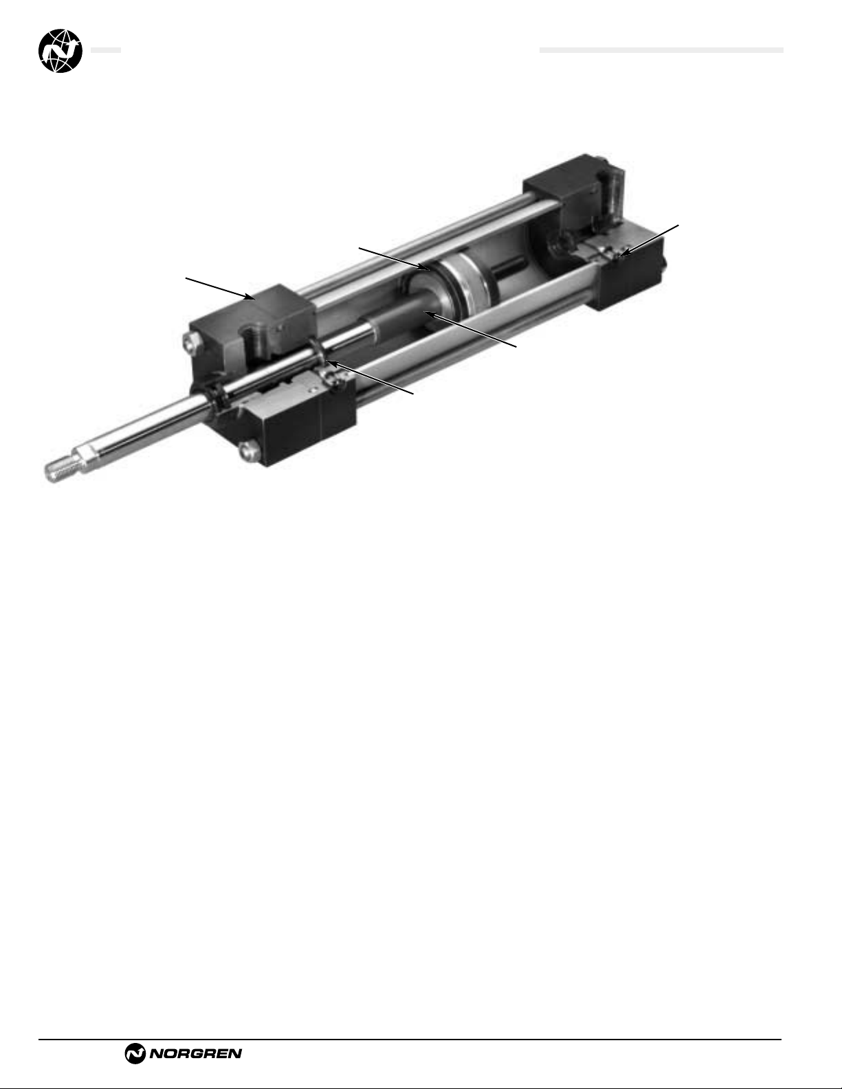
Series A Cylinders are constructed with the finest materials for each component!
2
1
7
3
6
6
4
5
8
9
4
13
12
12
11
10
9
Page 3
Brookville, OH USA Phone 937-833-4033 www.norgren.com
ACT-1-3
Series EA, NFPA Aluminum Air Cylinders (ø1-1/2" to 8"), Cylinder Features
12
2
2
3
4
7
13
8
1
11
9
4
8
10
Tie Rods: High-strength steel
maintains uniform compression on
tube end seals.
Cylinder Tube: High-strength
aluminum alloy ideally suited for air
service. The tube is clear anodized on the
O.D. and hard anodic coated on the I.D.,
resulting in a smooth, file hard (60RC),
corrosion and score resistant surface
finish.
Rod Seal: Nitrile lip-type seal is
pressure energized and wear
compensating for durability
and long life.
Rod Bearing: External removable
steel bearing housing (black oxide
finish), with an oil-impregnated
sintered iron rod bearing.
11
10
13
Ultra Cushion
®
Seals: Advanced
design features a unique, one-piece,
compound seal of nitrile* captured within
a precision machined groove. Linear and
radial “float” of the cushion seals
eliminates misalignment. Ultra Cushions
provide exceptionally fast “out of cushion”
stroke reversal. (Head and Cap Cushions
are optional.)
*Nitrile seals on the 5/8
" & 1" rod diameter.
For rod sizes 1-
3/8
" and larger, urethane seals are standard.
Impact Dampening Piston Seals:
Our impact dampening piston seals, in
conjunction with our advanced cushion
design, decelerate and reduce
end-of-stroke noise.
Piston: Machined solid aluminum
alloy, light-weight for low inertia, yet
strong. Threaded piston is installed with
high strength threadlocker adhesive then
staked to the piston rod.
O-Ring Tube Seal: Buna is standard.
(Viton is optional.)
2
1
3
Adjustable Captive Cushion Needle
(not shown): Fine thread allows
for safe and precision adjustment of
cushion. (See page 2.)
Wiper Seal: Lip-type urethane wiper
seal keeps contaminates from getting
into cylinder by aggressively wiping
foreign materials from the piston rod,
enhancing the rod seal life.
Piston Rod: Hard chrome plated
high-tensile steel, ground and polished.
4
7
5
Head/Cap: Precision machined from
alloy aluminum, then anodized for
corrosion resistance (black finish).
Wear Ring: Reinforced Teflon
®
compounded with polyphenylene sulfide
provides supreme wear and excellent
bearing support.
8
9
6
12
1
Series EA Ecology Cylinders are constructed with the finest
materials for each component!
6
Page 4
ACT-1-4
Brookville, OH USA Phone 937-833-4033 www.norgren.com
Series A & EA, NFPA Aluminum Air Cylinders, Impact Dampening Seals
Energy Absorption
Capacity of the Impact
Dampening Seals
The impact-dampening
Piston Seals in the Series EA cylinder
allow for guaranteed, repeatable cushioning.
The compressive qualities of the piston seals are
predictable. The degree of seal compression at
various supply pressures is documented. (See
Energy Absorption Chart.) This allows you to
compute the exact cylinder size required by
knowing the weight (pounds) you are stopping
at a given speed.
Series EA cylinders have a impact dampening
piston seal that accomplishes 80% of the actual
load stopping. The air cushion accounts for only
20%. (A conventional air cushioning cylinder
depends 100% on the compressibility of air to do
the stopping.) The EA seal absorbs high impact
loads allowing the effect of the air cushion to be
reduced by using a larger air cushion bleed
orifice. As a result the piston can move at a faster
speed for a longer period of time before the EA
seal does the final stopping.
See illustration at top of ACT-1-5 for cushion
operation.
3
Norgren Ecology Cylinders offer these advantages:
Norgren Guarantees
Non-lubricated Operation
for a Full Year!
The piston rod is self-lubricated by the
oil-impregnated rod bearing during operation.
Lubrication between piston and cylinder barrel
is derived from the polishing qualities of the
reinforced Teflon
®
wear ring.
The low friction surfaces extend the life of the
seals beyond normal expectations, permitting
Norgren to unconditionally guarantee nonlubricated
operation for one full year. See page ACT-1-98 for
complete warranty.
Series EA cylinders are NFPA interchangeable
and are available in many different mounting styles.
Operates Quietly
to Meet
OSHA Specifications.
Series EA cylinders provide substantial reductions
in impact noise, which reduces overall machine
noise and helps meet government regulations.
The summary of sound decibels chart illustrates the
operating sound levels.
The impact dampening qualities of the
Piston Seals are guaranteed for ONE FULL YEAR!
1 2
Summary of Sound Levels in Decibels
+Peak sound pressure is given in decibels (dB)
re:2 x 10⁵N/m2.
++End position of mike was 3' on centerline from end of
cylinder; side position of mike was 3' perpendicular to
centerline abeam of end of cylinder.
Note: At 5 feet, cylinder sound levels would be less by 9 dB
from side figure and 13 dB from end figure. The total noise
emitted will depend on the structure to which the cylinder is
attached. If it is mounted on a thin flat plate of considerable
area, the noise will be increased by a sounding board effect.
Effect of Impact Dampening Seals on Total Stroke of Cylinders
*The weight of the cylinder piston has been deducted from the figures shown above.
Note: The use of Viton
®
Seals limits the absorption of the impact dampening seals by 50%.
Energy Absorption Capacity of the Impact Dampening Seals
*Usable Pounds Stoppable at the Following Piston Speeds
This chart features the energy absorption capacity of the impact dampening piston seals
with Non-Adjustable cushions. For higher loads and velocities please refer to the Decel-Air™ Cushion
Option on ACT-1-10.
Note: These figures are for new cylinders. The impact dampening seals will take some compression set during operation
of the cylinder and the stroke loss will decrease. Also, the pressure at zero stroke loss will decrease to about 80 psi.
At pressures above those of zero stroke loss, a slight clicking sound may be produced during impact.
To determine the stroke loss for either the head or cap end, divide the value shown by 2.
In/Sec
Cylinder Bore
11/2 22
1
/2 31/4 45678
6 155.6 275.5 499.8 969.3 1505.4 2603.2 4159.8 5794.2 8067.6
12 38.4 68.1 123.4 239.7 372.6 644.8 1030.2 1435.8 2000.4
18 16.7 29.7 53.7 104.6 162.8 282.1 450.6 628.7 876.8
24 9.2 16.3 29.4 57.3 89.4 155.2 247.8 346.2 483.6
30 5.6 10.0 18.1 35.4 55.4 96.4 153.9 215.4 301.6
36 3.7 6.7 11.9 23.5 37.0 64.5 102.9 144.4 202.7
42 2.6 4.6 8.2 16.3 25.8 45.3 72.2 101.6 143.1
48 1.8 3.2 5.8 11.7 18.6 32.8 52.2 73.8 104.4
54 1.3 2.4 4.2 8.5 13.6 24.2 38.5 54.7 77.9
60 1.0 1.8 3.0 6.2 10.1 18.1 28.7 41.1 58.9
PSI
Cylinder Bore
11/
2 22
1
/
2 3
1
/
4 45678
0 .14 .15 .17 .19 .22 .25 .28 .32 .32
20 .10 .10 .12 .14 .16 .18 .20 .22 .22
40 .07 .07 .08 .09 .10 .12 .13 .14 .14
60 .04 .04 .05 .05 .06 .07 .07 .08 .08
80 .02 .02 .02 .02 .03 .03 .03 .04 .04
100000000000
PSI Air Sound
Cylinder Model
Pressure A133B3 EA155B3 A1133A3 EA1155A3
Level+
5" x 6" 5" x 6" 2" x 6" 2" x 6"
95
End++ 108 73 110 74
PSI+
Side++ 112 84 110 81
50
End++ 108 73 113 74
PSI+
Side++ 113 85 110 81
In/Sec
Cylinder Bore
11/2 22
1
/2 31/4 4 5678
6 279 495 899 1,744 2,709 4,685 7,486 10,429 4,520
12 68 122 221 430 699 1,159 1,854 2,583 3,800
18 30 53 95 187 291 507 810 1,130 1,576
24 16 29 52 102 160 279 444 622 869
30 10 18 32 63 99 172 275 387 541
36 6.7 12 21.6 42 66 116 183 259 363
42 4.7 8.3 14.7 29 46 81 129 181 257
48 3.4 5.7 10.4 21 33 59 93 131 187
54 2.3 4.3 7.6 15.3 24 43 68 97 138
60 1.8 3.2 5.4 11 18 33 52 74 106
Energy absorption capacity of the impact dampening
piston seals with an adjustable cushion.
Page 5
Brookville, OH USA Phone 937-833-4033 www.norgren.com
ACT-1-5
Series A & EA, NFPA Aluminum Air Cylinders (ø1-1/2" to 8"), Technical Features
Operating Temperatures:
Series EA -20˚F to 200˚F
(-29˚C to 107˚C)
with Viton Seals -20˚F to 400˚F
(-29˚C to 204˚C)
Operating Pressure:
250 PSIG Air (17 Bar)
EA Cylinders cannot be used
in hydraulic applications.
Bore Sizes: 1-1/2", 2", 2-1/2", 3-1/4",
4", 5", 6", 7", 8"
Supply:
Filtered compressed air to 250 PSI
Side Loading:
Cylinders are specifically designed to push and
pull. Side loading(misalignment)
of the piston rod should be avoided to ensure
maximum operating performance and life.
Care should be taken during installation
to properly align the load to be moved with the
center line of the cylinder.
The use of a rod alignment coupler (see
page ACT-1-94) is strongly recommended
whenever possible.
Lubrication:
None required
Norgren Air Cylinders are rated for “no lube
added” service. All internal components are
lubricated at time of assembly with a Teflon
®
based grease.
Materials:
Head and End Caps: black anodized
6061-T6 aluminum
Tube: 6063-T832 aluminum, clear
anodized O.D., hardcoat anodized I.D.
Rod: hard chrome plated steel
Piston: machined high-strength
aluminum alloy
Rod Bearing: oil impregnated sintered iron
Seals: nitrile rod seal, urethane rod wiper,
nitrile piston seals, nitrile tube end seals
Tie Rods: high-tensile strength steel
Air Cylinder Selection:
The proper application and selection of an air
cylinder requires full consideration of the
following: the fluid medium, operating
pressures, mounting style, length of stroke,
type of rod connection to the load, thrust or
mounting tension on the rod, mounting
attitude, speed of the stroke and how the load
motion will be stopped.
The data that follows provides the necessary
information in the evaluation of
an average application and will help you in
selecting the proper cylinder model and size
for your particular application.
Note: 1-1/2", 2", 2-1/2", 3-1/4", 4" and 5" bore
cylinders with 1/2" to 2" strokes will be
furnished with a short head cushion sleeve
and short cap cushion spear.
Only available on 5/8" and 1" rods.
The above specification applies to Series EA
cylinders with standard non-adjustable or
optional adjustable cushions.
Series EA Fixed Cushions
Piston and rod assembly
for 1-1/2" thru 5"
bore cylinders with
less than 1/2" stroke,
and 6" thru 8"
bore cylinders
with less than 2" stroke.
Piston and rod
assembly for
1-1/2" thru 5"
bore cylinders
with 1/2" to 2" stroke.
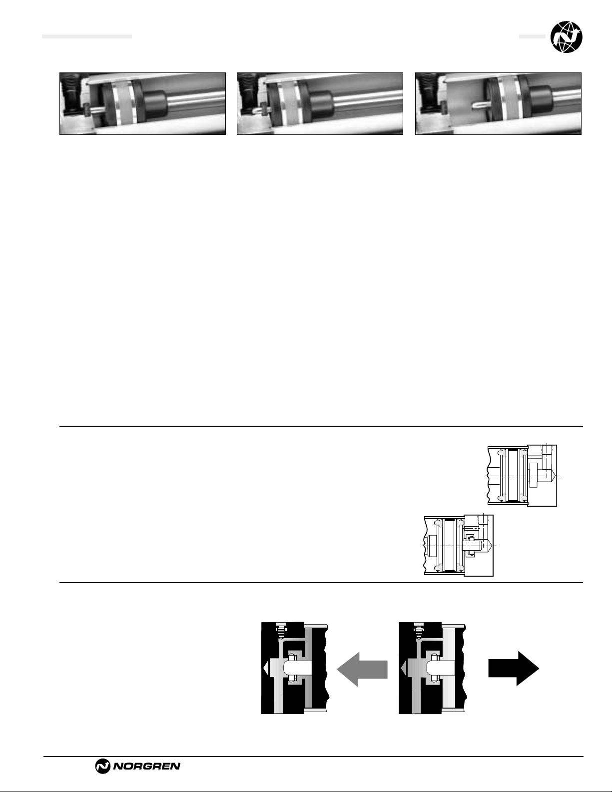
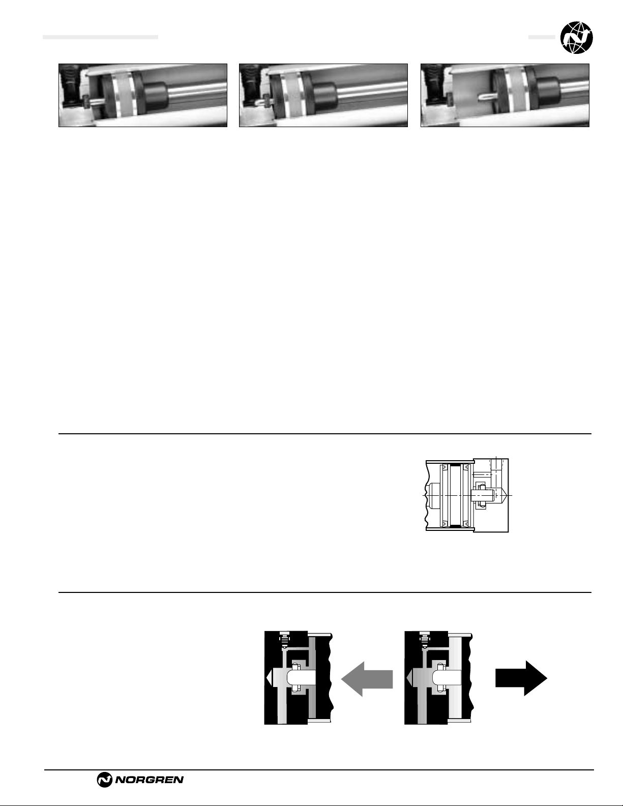
A Major Design and Performance Breakthrough in Air Cylinder Cushioning Systems!
Norgren’s advanced cushion design features a unique, onepiece, nitrile compound seal that is captured within a
precision machined groove. This allows both linear
and radial “float” of the cushion seal which
virtually eliminates problems associated
with misalignment. Integral flow paths
molded in the periphery of the seal provide
exceptionally fast “out of cushion” stroke
reversal without the use of ball checks.
Ultra Cushion
®
Figure 1 Figure 2 shows spear
exiting cushion seal.
On the reverse stroke the EJ seal releases its compressive
energy to propel the piston away from the end caps,
producing an immediate breakaway.
As the piston continues its travel to the point of impact
with the end caps, the compressive qualities of the EJ seal
provide the final decelerating force. This action compresses
the EJ seal and absorbs the remaining kinetic shock
vibration and noise created by the impact.
As the cushion spear enters the cushion cavity, the
exhaust port becomes sealed off creating an air brake.This
provides the initial deceleration in piston speed. The
oversized air cushion bleed orifice permits the cushion
pressure to exhaust with minimal restriction. This allows
the piston to move quickly and smoothly through the
cushion length.
Cushion Function
Page 6
ACT-1-6
Brookville, OH USA Phone 937-833-4033 www.norgren.com
Series J, NFPA Steel Air Cylinders (ø1-1/2" to 12"), Cylinder Features
Series J Cylinders are constructed with the finest materials for each component!
Ultra Cushion®Seals: Advanced
design features a unique, one-piece,
compound seal of nitrile* captured within
a precision machined groove. Linear and
radial “float” of the cushion seals
eliminates misalignment. Ultra Cushions
provide exceptionally fast “out of
cushion” stroke reversal. (Head and Cap
Cushions are optional.)
*Nitrile seals on the 5/8
" & 1" rod diameter.
For rod sizes 1-
3/8"
and larger, urethane seals are standard.
O-Ring Tube Seal: Buna is
standard. (Viton is optional.)
Cylinder Tube: High-strength
aluminum alloy 1-1/2", 2", 2-1/2" bore
anodized on the O.D. and hard coat I.D.
Steel cylinder tube hard chrome plated
I.D. 3-1/4" to 12" bore.
Tie Rods: High-strength steel
maintains uniform compression on
tube end seals.
Piston: Machined solid steel,
for high strength. Threaded piston is
installed with high strength threadlocker
adhesive then staked to the piston rod.
Adjustable Captive Cushion
Needle: A one-piece, precision threaded
brass cushion adjustment screw with a
threaded steel capture ring. It provides
safe and precise cushion adjustment.
6
Piston Seals: Long-wearing
nitrile seals.
Wear Ring: Reinforced Teflon
®
compounded with polyphenylene sulfide
provides supreme wear and excellent
bearing support.
Standard non-cushioned Series J cylinders are
recommended for applications that require full
bottoming of the piston and where the noise emitted
by the metal-to-metal impact between the piston and
cylinder end caps is tolerable. We recommend that
optional non-adjustable cushions be added for
piston speeds (moving light tools) ranging from 15
to 30 in/sec. For speeds exceeding 30 in/sec, the
cylinders should be equipped with adjustable air
cushions.
11
12
13
Piston Rod: Hard chrome plated
high-tensile steel, ground and polished.
Rod Bearing: External removable
threaded steel bearing housing (black
oxide finish), with an oil-impregnated
sintered iron rod bearing.
Rod Seal: Nitrile lip-type seal
is pressure energized and wear
compensating for durability and long life.
Head/Cap: Precision machined from
steel, then black oxide finished 1-1/2" to
2-1/2" bores. Painted black finish on
3-1/4" to 12" bores.
1
2
3
5
Wiper Seal: Lip-type urethane
wiper seal keeps contaminates
from getting into cylinder by
aggressively wiping foreign materials
from the piston rod, enhancing the
rod seal life.
Application Information
Series J NFPA interchangeable steel air cylinders
are offered with a variety of accessories, standard
and optional equipment to meet your application
needs.
7
8
9
The addition of a Teflon®wear ring to the outer
perimeter of the piston permits us to guarantee its
operation against failure due to lack of lubrication
for ONE FULL YEAR, regardless of cycles! See page
ACT-1-98 for complete warranty.
4
10
2
1
7
3
6
4
5
8
9
4
13
12
12
11
10
9
6
Page 7
Brookville, OH USA Phone 937-833-4033 www.norgren.com
ACT-1-7
Series J, NFPA Steel Air Cylinders (ø1-1/2" to 12"), Cylinder Features
Series EJ Ecology Cylinders are constructed with the finest
materials for each component!
Ultra Cushion®Seals: Advanced
design features a unique, one-piece,
compound seal of nitrile* captured
within a precision machined groove.
Linear and radial “float” of the cushion
seals eliminates misalignment. Ultra
Cushions provide exceptionally fast “out
of cushion” stroke reversal. (Head and
Cap Cushions are optional.)
*Nitrile seals on the 5/8
" & 1" rod diameter.
For rod sizes 1-
3/8
" and larger, urethane seals are standard.
Impact Dampening Piston Seals:
Our impact dampening piston seals, in
conjunction with our advanced cushion
design, decelerate and reduce
end-of-stroke noise.
Piston: Machined solid steel, for high
strength. Threaded piston is installed with
high strength threadlocker adhesive then
staked to the piston rod.
2
1
3
O-Ring Tube Seal: Buna is standard.
(Viton is optional.)
Adjustable Captive Cushion Needle
(not shown): Fine thread allows
for safe and precision adjustment of
cushion. (See page ACT-1-6.)
Wiper Seal: Lip-type urethane wiper
seal keeps contaminates from getting
into cylinder by aggressively wiping
foreign materials from the piston rod,
enhancing the rod seal life.
5
4
6
12
2
2
3
4
6
7
13
8
1
11
9
4
8
10
1
Tie Rods: High-strength steel
maintains uniform compression on
tube end seals.
Cylinder Tube: High-strength
aluminum alloy 1-1/2", 2". 2-1/2" bore
anodized on the O.D. and hard coat I.D.
Steel cylinder tube hard chrome plated
I.D. 3-1/4" to 12" bore.
Rod Seal: Nitrile lip-type seal is
pressure energized and wear
compensating for durability and long life.
Rod Bearing: External removable
steel bearing housing (black oxide
finish), with an oil-impregnated sintered
iron rod bearing.
11
10
13
Piston Rod: Hard chrome plated
high-tensile steel, ground and polished.
Head/Cap: Precision machined from
steel, then black oxide finished 1-1/2" to
2-1/2" bores. Painted black finish 3-1/4"
to 12" bores.
Wear Ring: Reinforced Teflon
®
compounded with polyphenylene sulfide
provides supreme wear and excellent
bearing support.
7
8
9
12
Page 8
ACT-1-8
Brookville, OH USA Phone 937-833-4033 www.norgren.com
Series J & EJ, NFPA Steel Air Cylinders, Impact Dampening Seals
PSI
Cylinder Bore
11/2 22
1
/2 31/4 456781012
0 .14 .15 .17 .19 .22 .25 .28 .32 .32 .36 .40
20 .10 .10 .12 .14 .16 .18 .20 .22 .22 .24 .26
40 .07 .07 .08 .09 .10 .12 .13 .14 .14 .15 .16
60 .04 .04 .05 .05 .06 .07 .07 .08 .08 .09 .10
80 .02 .02 .02 .02 .03 .03 .03 .04 .04 .04 .04
100000 00 0 00 00 0
In/Sec
Cylinder Bore
11/2 22
1
/2 31/4 456781012
6 155.6 275.5 499.8 969.3 1505.4 2603.2 4159.8 5794.2 8067.6 12,242 20,139
12 38.4 68.1 123.4 239.7 372.6 644.8 1030.2 1435.8 2000.4 3026 4971
18 16.7 29.7 53.7 104.6 162.8 282.1 450.6 628.7 876.8 1319.3 2162.1
24 9.2 16.3 29.4 57.3 89.4 155.2 247.8 346.2 483.6 722 1179
30 5.6 10.0 18.1 35.4 55.4 96.4 153.9 215.4 301.6 445.5 724
36 3.7 6.7 11.9 23.5 37.0 64.5 102.9 144.4 202.7 295.3 476.8
42 2.6 4.6 8.2 16.3 25.8 45.3 72.2 101.6 143.1 204.8 327.7
48 1.8 3.2 5.8 11.7 18.6 32.8 52.2 73.8 104.4 146 231
54 1.3 2.4 4.2 8.5 13.6 24.2 38.5 54.7 77.9 105.7 164.7
60 1.0 1.8 3.0 6.2 10.1 18.1 28.7 41.1 58.9 76.9 117.2
Energy Absorption
Capacity of the Impact
Dampening Seals
The impact-dampening
Piston Seals in the Series EJ cylinder
allow for guaranteed, repeatable cushioning.
The compressive qualities of the piston seals are
predictable. The degree of seal compression at
various supply pressures is documented. (See
Energy Absorption Chart.) This allows you to
compute the exact cylinder size required by
knowing the weight (pounds) you are stopping
at a given speed.
Series EJ cylinders have a impact dampening
piston seal that accomplishes 80% of the actual
load stopping. The air cushion accounts for only
20%. (A conventional air cushioning cylinder
depends 100% on the compressibility
of air to do the stopping.) The EJ seal absorbs
high impact loads allowing the effect of the air
cushion
to be reduced by using a larger air cushion bleed
orifice. As a result the piston can move at a faster
speed for a longer period of time before the EJ
seal does the final stopping. See illustration at top
of ACT-1-9 for cushion operation.
3
Norgren Ecology Cylinders offer these advantages:
Norgren Guarantees
Non-lubricated Operation
for a Full Year!
The piston rod is self-lubricated by the
oil-impregnated rod bearing during operation.
Lubrication between piston and cylinder barrel
is derived from the polishing qualities of the
reinforced Teflon
®
wear ring.
The low friction surfaces extend the life of the
seals beyond normal expectations, permitting
Norgren to unconditionally guarantee nonlubricated operation for one full year.
See page ACT-1-98 for complete warranty.
Series EJ cylinders are NFPA interchangeable
and are available in many different mounting styles.
Operates Quietly
to Meet
OSHA Specifications.
Series EJ cylinders provide substantial reductions in
impact noise, which reduces overall machine noise
and helps meet government regulations.
The summary of sound decibels chart illustrates the
operating sound levels.
The impact dampening qualities of the
Piston Seals are guaranteed for ONE FULL YEAR!
1 2
Summary of Sound Levels in Decibels
+Peak sound pressure is given in decibels (dB)
re:2 x 10⁵N/m2.
++End position of mike was 3' on centerline from end of
cylinder; side position of mike was 3' perpendicular to
centerline abeam of end of cylinder.
Note: At 5 feet, cylinder sound levels would be less by 9 dB
from side figure and 13 dB from end figure. The total noise
emitted will depend on the structure to which the cylinder is
attached. If it is mounted on a thin flat plate of considerable
area, the noise will be increased by a sounding board effect.
Effect of Impact Dampening Seals on Total Stroke of Cylinders
*The weight of the cylinder piston has been deducted from the figures shown above.
Note: The use of Viton®Seals limits the absorption of the impact dampening seals by 50%.
Energy Absorption Capacity of the Impact Dampening Seals
*Usable Pounds Stoppable at the Following Piston Speeds
This chart features the energy absorption capacity of the impact dampening piston seals
with a Non-Adjustable cushions. For higher loads and velocities please refer to the Decel- Air
Cushion option on ACT-1-10.
Note: These figures are for new cylinders. The impact dampening seals will take some compression set during operation
of the cylinder and the stroke loss will decrease. Also, the pressure at zero stroke loss will decrease to about 80 psi.
At pressures above those of zero stroke loss, a slight clicking sound may be produced during impact.
To determine the stroke loss for either the head or cap end, divide the value shown by 2.
PSI Air Sound
Cylinder Model
Pressure J133B3 EJ155B3 J1133A3 EJ1155A3
Level+
5" x 6" 5" x 6" 2" x 6" 2" x 6"
95
End++ 108 73 110 74
PSI+
Side++ 112 84 110 81
50
End++ 108 73 113 74
PSI+
Side++ 113 85 110 81
In/Sec
Cylinder Bore
11/2 221/2 31/4 456781012
6 279 495 899 1,744 2,709 4,685 7,486 10,429 4,520 22,035 36,250
12 68 122 221 430 699 1,159 1,854 2,583 3,800 5,446 8,947
18 30 53 95 187 291 507 810 1,130 1,576 2,374 3,891
24 16 29 52 102 160 279 444 622 869 1,299 1,414
30 10 18 32 63 99 172 275 387 541 801 1,303
36 6.7 12 21.6 42 66 116 183 259 363 531 856
42 4.7 8.3 14.7 29 46 81 129 181 257 367 588
48 3.4 5.7 10.4 21 33 59 93 131 187 262 415
54 2.3 4.3 7.6 15.3 24 43 68 97 138 189 295
60 1.8 3.2 5.4 11 18 33 52 74 106 138 211
Energy absorption capacity of the impact dampening
piston seals with an adjustable cushion.
Page 9
Brookville, OH USA Phone 937-833-4033 www.norgren.com
ACT-1-9
Series J & EJ, NFPA Steel Air Cylinders (ø1-1/2" to 12"), Technical Features
Operating Temperatures:
Series J -20°F to 200°F
(-29°C to 107°C)
with Viton Seals -20˚F to 400˚F
(-29˚C to 204˚C)
Operating Pressure:
250 PSIG Air (17.2 Bar)
400 PSIG Hydraulic (27.6 Bar)
Bore Sizes: 1-1/2", 2", 2-1/2", 3-1/4",
4", 5", 6", 7", 8", 10", 12"
Supply:
Filtered compressed air to 250 PSI Petroleum
based hydraulicfluid to 400 PSI
Side Loading:
Cylinders are specifically designed to push and
pull. Side loading (misalignment)
of the piston rod should be avoided to ensure
maximum operating performance and life.
Care should be taken during installation
to properly align the load to be moved with the
center line of the cylinder.
The use of a rod alignment coupler (see page
ACT-1-94 is strongly recommended whenever
possible.
Lubrication:
None required
Norgren Air Cylinders are rated for “no lube
added” service. All internal components are
lubricated at time of assembly with a Teflon
®
based grease.
Materials:
Head and End Caps: precision
machined steel
Tube: 6063-T832 aluminum, clear
anodized O.D., hard coat anodized I.D.
Rod: hard chrome plated steel
Piston: machined high-strength
aluminum alloy
Rod Bearing: oil impregnated sintered iron
Seals: nitrile rod seal, urethane rod wiper,
nitrile piston seals, nitrile tube
end seals
Tie Rods: high-tensile strength steel
Air Cylinder Selection:
The proper application and selection of an air
cylinder requires full consideration of the
following: the fluid medium, operating
pressures, mounting style, length of stroke,
type of rod connection to the load, thrust or
mounting tension on the rod, mounting
attitude, speed of the stroke and how the load
motion will be stopped.
The data that follows provides the necessary
information in the evaluation of
an average application and will help you in
selecting the proper cylinder model and size
for your particular application.
Note: 1-1/2", 2", 2-1/2", 3-1/4", 4" and 5" bore
cylinders with 1/2" to 2" strokes will be
furnished with a short head cushion sleeve
and short cap cushion spear.
Only available on 5/8" and 1" rods.
The above specification applies to Series J
cylinders with optional non-adjustable or
adjustable cushions.
Series J Fixed Cushions
Piston and rod
assembly for
1-1/2" thru 5"
bore cylinders
with 1/2" to 2" stroke.
On the reverse stroke the EJ seal releases its compressive
energy to propel the piston away from the end caps,
producing an immediate breakaway.
As the piston continues its travel to the point of impact
with the end caps, the compressive qualities of the EJ seal
provide the final decelerating force. This action compresses
the EJ seal and absorbs the remaining kinetic shock
vibration and noise created by the impact.
As the cushion spear enters the cushion cavity, the
exhaust port becomes sealed off creating an air brake.This
provides the initial deceleration in piston speed. The
oversized air cushion bleed orifice permits the cushion
pressure to exhaust with minimal restriction. This allows
the piston to move quickly and smoothly through the
cushion length.
A Major Design and Performance Breakthrough in Air Cylinder Cushioning Systems!
Norgren’s advanced cushion design features a unique, onepiece, nitrile compound seal that is captured within a
precision machined groove. This allows both linear
and radial “float” of the cushion seal which
virtually eliminates problems associated
with misalignment. Integral flow paths
molded in the periphery of the seal provide
exceptionally fast “out of cushion” stroke
reversal without the use of ball checks.
Ultra Cushion
®
Figure 1 Figure 2 shows spear
exiting cushion seal.
Cushion Function
Page 10
ACT-1-10
Brookville, OH USA Phone 937-833-4033 www.norgren.com
Series A & EA, NFPA Aluminum Decel-Air Cushioned Cylinder
Series J & EJ, NFPA Steel Decel-Air Cushioned Cylinder
Explanation of Decel-Air Cushion:
Norgren’s Decel Cushioned cylinder was designed for
applications where high velocity, low mass, material transfer or
machine function is required, and where the kinetic energy to
be absorbed during cushioning exceeds the parameters of our
standard Series EA or EJ air cylinders equipped with nonadjustable or adjustable cushions. Decel cushions employ
longer-than-standard air cushions to assist our Impact
Dampening Piston Seal.
Why does our Decel-Air Cushion work?
The extra cushion length of the Decel cushioned cylinder
provides an additional deceleration capability to slow the
cylinder’s moving mass to a point where the positive
cushioning effect of our Impact Dampening Piston Seals can
perform the final cushioning.
Norgren’s Decel-Air Cushioned Cylinders
Versus
Cylinder Mounted Shock Absorbers
The first extensive evaluation of pneumatic cylinder cushion
performance was undertaken by the Mechanical Engineering
Department of The Ohio State University. The test was
conducted on 2-1/2” bore, 12” stroke.
The OSU tests found the Decel Cushioned cylinders absorbed
almost three times as much kinetic energy with a lower level of
peak cushion as a standard Ecology seal configured cylinder.
Because air is compressible and is exhausted out of the
cylinder each cycle, the internal heat buildup is minimized. The
“Maximum Inch Pounds Per Hour” rating which is essential in
determining the effectiveness of shock absorber performance
is not needed to judge Decel cushion performance.
The test indicated that Norgren Decel-Air Cushioned cylinders
could prove to be superior to a hydralic shock absorber
assisted cylinder for high cycle, high velocity applications with
light to moderate loading (precisely the area where most
severe cylinder applications exist). The cycle rates and the
cushioning times of the Decel-Air Cushioned cylinders and the
hydraulic shock absorber assisted cylinders were
comparable.*
Decel-Air Cushioned cylinders are also less costly than shock
absorber mounted cylinders and are self-contained units.
*For comparative evaluation, a well-known hydraulic shock
absorber was chosen. The OSU tests showed a smooth shockabsorbing operation was achieved at very low velocities using
the shock absorbers, but at comparable Decel Cushion cylinder
velocities, a high mechanical impact took place on the shock
absorber mounted cylinder.
Potential Decel-Air Cushion Applications
1. Conveyors & Material Handling Equipment
2. Transfer Machines & Shuttle Tables
3. Packaging Machinery
4. Foundry Equipment
5. Automatic Gate Opening & Closing
Decel-Air™ Cushioned Cylinder
Eliminates the need for shock absorbers on air cylinder applications.
Ultra Cushion Seals are made of nitrile*
captured within a precision machined groove.
The seal’s linear and radial “float” eliminates
misalignment and provides exceptionally fast
“out of cushion” stroke reversal.
*Nitrile seals on the 5/8" and 1" rod diameter. For rod
sizes 1-3/8" and larger urethane seals are standard.
Extra cushion sleeve and
stud length for longer
deceleration
Decel-Air Cushion Spacer
Block allows for extra
cushion length and longer
deceleration
Impact Dampening
“Ecology” Piston Seals
absorb final impact and
provide end of stroke
cushioning assistance.
Adjustable Captive
Cushion Needle is a
one-piece, precision
threaded brass cushion
adjustment screw with a
threaded steel capture
ring. It provides safe and
precise cushion
adjustment
Page 11
Brookville, OH USA Phone 937-833-4033 www.norgren.com
ACT-1-11
Series A & EA, NFPA Aluminum Decel-Air Cushioned Cylinder
Series J & EJ, NFPA Steel Decel-Ar Cushioned Cylinder
All Dimensions in Inches (mm)
In/ Cylinder Bore
Sec 1-1/2 2 2-1/2 3-1/4 4 5 6 7 8 10 12
6 558 990 1.798 3.488 5.418 9.370 14.972 20.040 20.858 44.070 72.500
12 136 244 442 860 1.338 2.318 3.708 5.166 7.600 10.892 17.894
18 60 106 190 374 582 1.014 1.620 2.260 3.152 4.748 7.782
24 32 58 104 204 320 558 888 1.244 1.738 2.598 2.828
30 20 36 64 126 198 344 550 774 1.082 1.602 2.606
36 13.4 24 43 84 132 232 366 518 726 1.062 1.712
42 9.4 16.6 29 58 92 162 258 362 514 734 1.176
48 6.8 11.4 20.8 42 66 118 186 262 374 524 830
54 4.6 8.6 10.8 30 48 86 136 194 276 378 590
Decel Cushioned Cylinder
Fully Cushioned Load Stopping Capacity in Pounds*
*Include piston rod wight in total load to be stopped.
NOTE:
• All dimensions not shown are per STD NFPA dimensions
• For cylinders with (1) Decel Cushion AOL dimension wil be “MB”-“J”.
Piston Rod Dia. Weights*
5/8" - .30 lb. + 0.09 lb./in. stroke
1" - .90 lb. + 0.22 lb./in. stroke
1-3/8" - 2.2 lb. + 0.42 lb./in. stroke
1-3/4" - 4.0 lb. + 0.68 lb./in. stroke
2" - 5.5 lb. + 0.90 lb./in. stroke
2-1/2" - 10.1 lb. + 1.40 lb./in. stroke
Double Weight for double rod end cylinders
● The Decel Cushioned cylinder increases the kinetic
energy absorption capability by increasing the effective
cushion spear length in the cylinder.
● The Decel Cushioned cylinder increases the standard
cushion spear length by 100%, allowing an increase in
kinetic energy absorption capability by two times.
Decel Cushioned cylinder envelope dimensions are not NFPA
dimensionally interchangeable over the stroke length.
NOTE: See page ACT-1-8 for “Effect of Impact Dampening
Seals on Total Stroke of Cylinders,” and page ACT-1-19 for
Rod End Dimensions.
Cyl. Add Stroke
Bore G J MB
1-1/2 1-1/2 1 5-5/8
2 1-1/2 1 5-5/8
2-1/2 1-1/2 1 5-3/4
3-1/4 1-3/4 1-1/4 6-3/4
4 1-3/4 1-1/4 6-3/4
5 1-3/4 1-1/4 7
6 2 1-1/2 8
7 2 1-1/2 8-1/8
8 2 1-1/2 8-1/8
Basic Envelope Dimensions
G
J
MB + Stroke
JJ
Page 12
ACT-1-12
Brookville, OH USA Phone 937-833-4033 www.norgren.com
Series EA, NFPA Aluminum Air Cylinders (ø1-1/2" to 8"), Impact Dampening Seals
Series EJ, NFPA Steel Air Cylinders (ø1-1/2" to 12"), Impact Dampening Seals
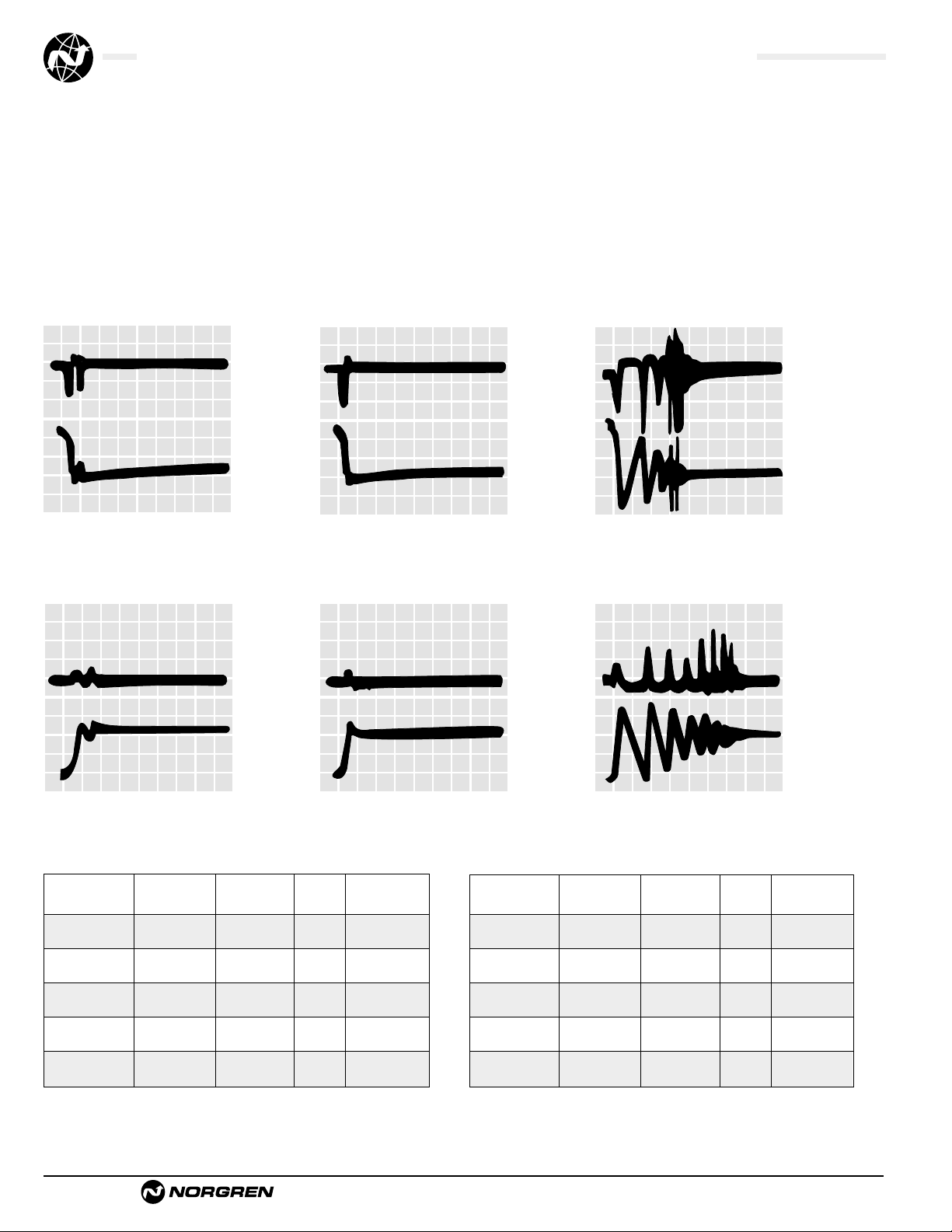
Cylinders with Weight attached Cushion Efficiency Cushioning Bounce Cycles
Cushions to Piston Rod (lbs) (G’s* Created) Time (Ms) During Cushioning
Norgren Ecology
Adjustable 54 5.25 40.00 3.25
Norgren Ecology
Non-Adjustable 54 12.00 28.75 2.75
Competitor A
Adjustable 54 11.50 92.50 6.75
Competitor B
Adjustable 54 8.00 77.50 5.25
Competitor C
Adjustable 54 6.50 67.50 6.25
Cylinders with Weight attached Cushion Efficiency Cushioning Bounce Cycles
Cushions to Piston Rod (lbs) (G’s* Created) Time (Ms) During Cushioning
Norgren Ecology
Adjustable 8.5 14.50 25.00 1.00
Norgren Ecology
Non-Adjustable 8.5 17.50 26.25 1.75
Competitor A
Adjustable 8.5 48.00 107.50 7.25
Competitor B
Adjustable 8.5 32.75 102.50 6.50
Competitor C
Adjustable 8.5 50.50 81.25 9.25
2" Bore Cap End Cushion Test
Average deceleration force = 10 G's
Time consumed during cushioning = 0.020 sec.
Number of bounces:
1
/2 Pneumatic – 0 Metallic
*Measured in G’s of deceleration force created. All cylinders tested were NFPA types,
front flange mounting, 6" stroke with standard diameter piston rods.
Velocity: 1 div.
= 20 in/sec.
14.5 lbs.
added to rod
Velocity: 1 div.
= 20 in/sec.
14.5 lbs.
added to rod
Velocity: 1 div.
= 20 in/sec.
2.5 lbs. added
to rod
Tests by the Milwaukee School of Engineering confirm
Ecology Cylinder Cushions are more efficient, faster acting
and bounce less!
2" Bore Cylinder Tests Results
Figures shown are average and not the result of each individual test. Piston velocity was
regulated at 45 in/sec.
COMPETITIVE CYLINDERS
with Adjustable Cushions
Velocity: 1 div.
= 20 in/sec.
14.5 lbs.
added to rod
Velocity: 1 div.
= 20 in/sec.
14.5 lbs.
added to rod
Acceleration:
1 div. = 10
G’s
X Axis: 1 div.
= .03 seconds
Acceleration:
1 div. = 10
G’s
X Axis: 1 div.
= .03 seconds
Acceleration:
1 div. = 10 G’s
X Axis: 1 div. =
.02 seconds
Acceleration:
1 div. = 10
G’s
X Axis: 1 div.
= .03 seconds
Velocity: 1 div.
= 20 in/sec.
2.5 lbs.
added to rod
Acceleration:
1 div. = 10
G’s
X Axis: 1 div.
= .03 seconds
NORGREN ECOLOGY CYLINDERS
with Adjustable Cushions
NORGREN ECOLOGY CYLINDERS
with Non-Adjustable Cushions
2" Bore Rod End Cushion Test
Average deceleration force = 15 G's
Time consumed during cushioning = 0.030 sec.
Number of bounces: 1 Pneumatic – 1 Metallic
2" Bore Cap End Cushion Test
Average deceleration force = 60 G's
Time consumed during cushioning = 0.120 sec.
Number of bounces: 3 Pneumatic – 4 Metallic
2" Bore Rod End Cushion Test
Average deceleration force = 78 G's
Time consumed during cushioning = 0.120 sec.
Number of bounces: 2 Pneumatic – 4 Metallic
2" Bore Rod End Cushion Test
Average deceleration force = 20 G's
Time consumed during cushioning = 0.015 sec.
Number of bounces:
1
/2 Pneumatic – 0 Metallic
2" Bore Cap End Cushion Test
Average deceleration force = 17.5 G's
Time consumed during cushioning = 0.025 sec.
Number of bounces: 1 Pneumatic – 1 Metallic
*Measured in G’s of deceleration force created. All cylinders tested were NFPA types,
front flange mounting, 6" stroke with standard diameter piston rods.
4" Bore Cylinder Tests Results
Figures shown are average and not the result of each individual test. Piston velocity was
regulated at 25 in/sec.
Acceleration:
1 div. = 10
G’s
X Axis: 1 div.
= .03 seconds
Page 13
Brookville, OH USA Phone 937-833-4033 www.norgren.com
ACT-1-13
Series A & EA, NFPA Aluminum Air Cylinders, Technical Information
Series J & EJ, NFPA Steel Air Cylinders, Technical Information
1.77 71 106 142 177 266 353 .00102
3.14 126 189 251 314 471 628 .00182
4.91 196 295 393 491 737 982 .00284
8.30 332 498 664 830 1245 1659 .00480
12.57 503 754 1005 1257 1886 2513 .00727
19.64 785 1178 1571 1964 2946 3928 .01137
28.27 1130 1696 2262 2827 4240 5654 .01636
38.49 1540 2309 3079 3849 5774 7698 .02227
50.26 2010 3015 4020 5026 7539 10052 .02909
78.54 3141 4712 6283 7854 11781 15700 .04545
113.10 4524 6786 9048 11310 16965 22620 .06545
(11.40) (315) (472) (629) (786) (1179) (1570) (29)
(20.27) (559) (839) (1119) (1398) (2097) (2793) (52)
(31.67) (874) (1311) (1748) (2185) (3277) (4368) (80)
(53.32) (1477) (2215) (2953) (3692) (5538) (7379) (136)
(81.07) (2237) (3355) (4473) (5592) (8388) (11178) (206)
(126.71) (3491) (5240) (6988) (8736) (13104) (17472) (322)
(182.39) (5026) (7544) (10061) (12574) (18860) (25149) (463)
(247.91) (6831) (10242) (13658) (17074) (25613) (34148) (631)
(324.26) (8940) (13411) (17881) (22356) (33533) (44711) (829)
(506.74) (13974) (20961) (27948) (34935) (52402) (69834) (1282)
(729.72) (20123) (30184) (40246) (50307) (75460) (100614) (1852)
Volume
Cu Ft (cm
3
)
Bore Piston
PSI (bar)
Displacement
Area 40 (3) 60 (4) 80 (6) 100 (7) 150 (10) 200 (14) Per Inch
1
1
/2"
2"
2
1
/2"
3
1
/4"
4"
5"
6"
7"
8"
10"
12"
All Dimensions in Inches (mm)
All Forces in Pounds (Newtons)
Cylinder Area (sq. in.)
Bore
1-1/2" 1.77
2" 3.14
2-1/2" 4.91
3-1/4" 8.30
4" 12.57
5" 19.64
6" 28.27
7" 38.49
8" 50.26
10" 78.54
12" 113.10
Volume
Cu Ft (cm
3
)
Rod Rod
PSI (bar)
Displacement
Area 40 (3) 60 (4) 80 (6) 100 (7) 150 (10) 200 (14) Per Inch
5
/8"
1"
1
3
/8"
1
3
/4"
2"
2
1
/2"
.307 12 18 25 31 46 61 .00018
.785 31 47 63 78 118 157 .00045
1.485 59 89 119 149 222 297 .00086
2.404 96 144 192 240 360 480 .00139
3.142 126 189 251 314 471 628 .00182
4.909 196 295 393 491 736 981 .00284
(1.98) (53) (80) (111) (138) (205) (271) (5)
(5.06) (138) (209) (280) (351) (525) (698) (13)
(9.58) (262) (396) (529) (663) (997) (1321) (24)
(15.51) (423) (641) (854) (1068) (1601) (2135) (39)
(20.16) (559) (839) (1118) (1398) (2096) (2795) (52)
(31.67) (873) (1310) (1747) (2184) (3275) (4367) (80)
Deduct these Forces for Retract Strokes
Cylinder Force and Volume Charts
Extend Forces in pounds (newtons)
Bore Size Selection:
Use the following formulas in the selection
of the proper bore size:
• Extended force in pounds =
Bore area (in
2
) times
pressure to cap in psig.
• Retract force in pounds =
Bore area minus rod area (in
2
)
times pressure to head in psig.
Bore Areas
NOTE:
A & EA Bore Sizes (1-1/2" – 8")
J & EJ Bore Sizes (1-1/2" – 12")
NOTE:
A & EA Rod Dia. (5/8" – 1-3/4")
J & EJ Rod Dia. (5/8" – 2-1/2")
Rod Areas
Rod Area (sq. in.)
Diameter
5/8" .31
1" .78
1-3/8" 1.49
1-3/4" 2.41
2" 3.14
2-1/2" 4.91
Page 14
ACT-1-14
Brookville, OH USA Phone 937-833-4033 www.norgren.com
Series A & EA, NFPA Aluminum Air Cylinders, Technical Information
Series J & EJ, NFPA Steel Air Cylinders, Technical Information
Piston Rod Diameter Selection:
Applications requiring long extend (push) strokes may require
oversize piston rod diameters to prevent buckling.
To determine the correct rod diameter for your application
follow these simple steps:
1. Select the thrust from the Cylinder Force and Volume Chart
(page ACT-1-13) that is required for your application.
Thrust = Piston Surface Area x Operating Pressure
2. From the Cylinder Mounting Diagram Chart
(page ACT-1-15) select the mounting style being used.
3. With the piston rod fully extended, calculate the value of L (in
inches). Multiply cylinder stroke by appropriate stroke factor
located in Cylinder Mounting Diagram Chart to obtain
effective length L.
4. Locate the value of L (in inches) from the Determining
Adequate Rod Diameter Chart.
5. Selecting Stop Tubes: Stop tubes enhance the transverse load
carrying capability of a long stroke cylinder by increasing the distance
between the piston and rod bearing at full extension (Refer to page
ACT-1-87). When the value of L (calculated from the Adequate Rod
Diameter Chart) is less than 40", a stop tube is not required.
However, if L is 40" or more, 1" of stop tube is recommended for every
10" (or fraction thereof) over 40".
6. Recommended Mounting Styles for Maximum Stroke and
Thrust Load:
• Multiply cylinder stroke by appropriate stroke factor to obtain
effective length L.
• If cylinder has extra rod extension, add this extension to the stroke
length before obtaining effective length.
Tie Rod Tightening:
In order to reduce the possibility of cylinder binding or damage,
tighten to quarter unit increments of the final torque value in the
following order: #1, #2, #3, #4.
Then torque fully to the recommended foot pounds in the same order.
Determining Adequate Rod Diameter Chart
Note: In some cases it may be necessary to use a larger bore cylinder than is required
for force in order to obtain an adequate rod diameter.
Recommended Torques for Tightening Tie Rods
Extended Maximum effective length “L”
Force recommended for rod diameters
(lbs)
5/8" 1" 1-3/8" 1-3/4" 2" 2-1/2"
50 95 – – – – –
100 65 170 – – – –
150 50 135 260 – – –
200 43 115 220 – – –
300 34 93 180 300 – –
500 25 70 135 250 – –
750 20 56 110 185 250 –
1000 17 48 94 160 220 –
1500 13 38 80 130 170 260
2000 11 33 64 110 140 225
3000 9 26 51 90 115 180
4000 7 22 44 75 100 155
5000 – 20 39 66 88 140
6000 – 18 35 60 79 125
8000 – 15 30 52 68 110
10000 – 12 26 46 60 95
12500 – 10 22 41 52 86
15000 – – 19 37 48 79
20000 – – 14 29 41 68
Cylinder Standard Stainless Steel
Bore Steel Tie Rods Tie Rods
1-1/2" 6.6 ft. lbs. 3.75 ft. lbs.
2" 11 ft. lbs. 7.5 ft. lbs.
2-1/2" 13 ft. lbs. 7.5 ft. lbs.
3-1/4" 20 ft. lbs. 13-14 ft. lbs.
4" 24 ft. lbs. 13-14 ft. lbs.
5" 40 ft. lbs. 33 ft. lbs.
6" 48 ft. lbs. 33 ft. lbs.
7" & 8" 100 ft. lbs. 65 ft. lbs.
10" 150 ft. lbs. 75 ft. lbs.
12" 175 ft. lbs. 87.5 ft. lbs.
1
4
3
2
Page 15
Brookville, OH USA Phone 937-833-4033 www.norgren.com
ACT-1-15
Series A & EA, NFPA Aluminum Air Cylinders (ø1-1/2" to 8"), Technical Information
Series J & EJ, NFPA Steel Air Cylinders (ø1-1/2" to 12"), Technical Information
Cylinder Rod End Example Stroke
Mounting Connection Factor
Side Tapped, Head or Fixed and
Cap Flange, Tie Rod, Rigidly Guided .50
Center or Side Lug
Side Tapped, Head or Pivoted and
Cap Flange, Tie Rod, Rigidly Guided .70
Center or Side Lug
Side Tapped, Head or Supported but
Cap Flange, Tie Rod, not Rigidly Guided 2.00
Center or Side Lug
Side Tapped, Head or
Cap Flange, Tie Rod, None 5.00
Center or Side Lug
Head Trunnion Pivoted and 1.00
Rigidly Guided
Center Trunnion Pivoted and 1.50
Rigidly Guided
Cap Trunnion Pivoted and
or Clevis Rigidly Guided 2.00
Number of Tie Rod Supports Required
Cylinder Cylinder Stroke (in)
Bore 60 75 95 115 135
1-1/2" 1 1 2 2 3
2" – 1 1 2 2
2-1/2" – – 1 1 1
3-1/4" – – – 1 1
4" ––––1
5" and over – – – – –
Tie Rod Supports:
For long strokes, tie rod supports are provided.
These supports are of the same envelope dimensions as
the cylinder end caps.
NOTE: See chart for number of tie rod supports required.
Cylinder Mounting Diagram Chart
Page 16

ACT-1-16
Brookville, OH USA Phone 937-833-4033 www.norgren.com
Series A & EA, NFPA Aluminum Air Cylinders (ø1-1/2 to 8"), Technical Information
Series J & EJ, NFPA Steel Air Cylinders (ø1-1/2 to 12"), Technical Information
(15.88) (1.42) (1.67) (1.67) (1.48) (1.73) (2.24) (1.76) (1.42) (1.87) (2.24) (.08)
(15.88) (2.27) (2.67) (2.67) (2.35) (2.58) (3.46) (2.61) (2.27) (2.82) (3.46) (.13)
(25.40) (2.33) (2.73) (2.73) (2.42) (2.64) (3.52) (2.67) (2.33) (2.89) (3.52) (.19)
(15.88) (3.26) (3.68) (3.68) (3.35) (3.57) (4.68) (3.60) (3.26) (4.20) (4.68) (.18)
(25.40) (3.32) (3.75) (3.75) (3.41) (3.64) (4.74) (3.66) (3.32) (4.26) (4.74) (.25)
(25.40) (5.02) (6.50) (6.50) (5.16) (5.30) (7.63) (5.70) (5.02) (7.26) (7.63) (.33)
(34.93) (5.11) (6.59) (6.59) (5.25) (5.39) (7.72) (5.79) (5.11) (7.35) (7.72) (.42)
(25.40) (9.22) (11.29) (11.29) (9.36) (9.45) (12.43) (9.90) (9.22) (12.20) (12.43) (.37)
(34.93) (9.31) (11.38) (11.38) (9.45) (9.54) (12.52) (9.99) (9.31) (12.29) (12.52) (.50)
(25.40) (15.72) (18.33) (18.33) (15.97) (17.25) (19.60) (16.49) (15.72) (19.60) (19.60) (.45)
(34.93) (15.81) (18.42) (18.42) (16.06) (17.34) (19.69) (16.58) (15.81) (19.69) (19.69) (.54)
(34.93) (24.09) (29.02) (29.02) (24.66) (25.59) (29.65) (25.93) (24.09) (39.81) (29.65) (.76)
(44.45) (24.21) (31.41) (31.41) (24.78) (25.72) (29.77) (26.05) (24.21) (30.93) (29.77) (.88)
(34.93) (33.14) (33.14) (33.14) (33.60) (34.73) (43.58) (38.59) (33.14) — (43.58) (.80)
(44.45) (33.26) (33.26) (33.26) (33.71) (34.85) (43.70) (38.71) (33.26) — (43.70) (.91)
(34.93) (41.88) (41.88) (41.88) (42.50) (43.47) (54.48) (44.41) (41.88) — (54.48) (.99)
(44.45) (42.00) (42.00) (42.00) (42.62) (43.59) (54.60) (44.52) (42.00) — (54.60) (1.11)
(44.45) (81.66) (81.66) (81.66) (82.46) (83.65) (103.51) (84.50) (81.66) — (103.51) (1.56)
(50.80) (81.72) (81.76) (81.76) (82.55) (83.74) (103.61) (84.59) (81.76) — (103.61) (1.65)
(50.80) (130.75) (130.75) (130.75) (131.21) (133.02) (172.52) (134.84) (130.75) — (172.52) (1.87)
(63.50) (130.98) (130.98) (130.98) (131.43) (133.25) (172.75) (135.20) (130.98) — (172.75) (2.10)
Mounting Code
Bore Rod
Add Per Inch
Inch (mm) Inch (mm) 01, 05, 16 03 04 06 07, 08, 09 11 12 15 20, 21, 22, 32 10, 42, 52 of Stroke
1
1
/2" (38.10)
2" (50.80)
2
1
/2" (63.50)
3
1
/4" (82.55)
4" (101.60)
5" (127.00)
6" (152.40)
7" (177.80)
8" (203.20)
10" (254.00)
12" (304.80)
5/8" 3.1 3.7 3.7 3.2 3.8 4.9 3.9 3.1 4.1 4.9 .18
5/8" 5.0 5.9 5.9 5.2 5.7 7.6 5.8 5.0 6.2 7.6 .28
1" 5.1 6.0 6.0 5.3 5.8 7.8 5.9 5.1 6.4 7.8 .42
5/8" 7.2 8.1 8.1 7.4 7.9 10.3 7.9 7.2 9.3 10.3 .40
1" 7.3 8.3 8.3 7.5 8.0 10.5 8.1 7.3 9.4 10.5 .54
1" 11.1 14.3 14.3 11.4 11.7 16.8 12.6 11.1 16.0 16.8 .72
13/8" 11.3 14.5 14.5 11.6 11.9 17.0 12.8 11.3 16.2 17.0 .92
1" 20.3 24.9 24.9 20.6 20.8 27.4 21.8 20.3 26.9 27.4 .81
13/8" 20.5 25.1 25.1 20.8 21.0 27.6 22.0 20.5 27.1 27.6 1.1
1" 34.6 40.4 40.4 35.2 38.0 43.2 36.3 34.6 43.2 43.2 .98
1
3
/8" 34.8 40.6 40.5 35.4 38.2 43.4 36.5 34.8 43.4 43.4 1.18
13/8" 53.1 63.9 63.9 54.3 56.4 65.3 57.1 53.1 68.1 65.3 1.68
13/4" 53.3 64.2 64.2 54.6 56.7 65.6 57.4 53.3 68.1 65.6 1.94
13/8" 73.0 73.0 73.0 74.0 76.5 96.0 85.0 73.0 96.0 1.75
13/4" 73.3 73.3 73.3 74.3 76.8 96.3 85.3 73.3 96.3 2.01
13/8" 92.3 92.3 92.3 93.6 95.8 120.0 97.8 92.3 120.0 2.18
13/
4" 92.5 92.5 92.5 93.9 96.0 120.3 98.1 92.5 120.3 2.44
1
3
/4" 179.9 179.9 179.9 181.6 184.3 228.0 186.1 179.9 228.0 3.43
2" 180.0 180.1 180.1 181.8 184.5 228.2 186.3 180.1 228.2 3.64
2" 288.0 288.0 288.0 289.0 293.0 380.0 297.0 288.0 380.0 4.12
21/
2" 288.5 288.5 288.5 289.5 293.5 380.5 297.5 288.5 380.5 4.62
5/8" 1.9 2.6 2.7 2.1 2.5 2.3 2.8 2.5 3.0 2.8 0.18
5/8" 2.8 3.9 4.0 3.1 3.5 3.3 4.0 3.8 4.2 3.9 0.21
1" 3.4 4.4 4.6 3.7 4.1 3.9 4.6 4.4 4.8 4.5 0.35
5/8" 3.9 5.3 5.5 4.1 4.6 4.4 5.3 5.3 5.5 5.3 0.23
1" 4.5 5.9 6.1 4.7 5.2 5.1 5.9 6.0 6.1 5.9 0.38
1" 7.3 10.8 11.1 7.7 8.9 8.2 11.1 9.7 11.8 11.4 0.42
13/8" 8.2 11.5 12.1 8.7 9.9 9.2 12.1 10.7 12.8 12.4 0.63
1" 9.8 14.8 15.1 10.2 11.5 10.9 14.8 13.3 15.5 15.2 0.45
13/8" 10.8 15.5 16.1 11.2 12.5 11.9 15.8 14.3 16.5 16.2 0.66
1" 15.1 22.7 23.1 16.1 18.7 17.6 22.2 20.8 22.8 22.5 0.51
13/8" 16.2 23.5 24.1 17.2 19.7 18.6 23.2 21.9 23.9 23.5 0.73
13/8" 23.5 35.6 36.3 24.5 27.3 26.6 35.7 32.1 37.0 36.3 0.77
13/4" 24.8 36.9 37.6 25.8 28.3 27.9 37.0 33.4 38.3 37.6 1.03
1
3
/8" 32.1 32.1 32.1 33.4 33.5 36.8 35.2 32.1 48.9 48.2 1.00
13/4" 33.4 33.4 33.4 34.7 34.8 38.1 36.5 33.4 50.2 49.5 1.26
13/8" 40.0 40.0 40.0 41.3 41.4 45.7 43.0 40.0 60.5 59.7 1.06
13/4" 47.3 41.3 41.3 42.6 42.7 47.0 44.3 41.3 61.8 61.0 1.32
(15.88) (.86) (1.18) (.23) (.95) (1.13) (1.04) (1.27) (1.13) (1.36) (1.27) (.08)
(15.88) (1.27) (.77) (1.81) (1.41) (1.59) (1.50) (1.81) (1.72) (1.91) (1.77) (.10)
(25.40) (1.54) (2.00) (2.09) (1.68) (1.86) (1.77) (2.09) (2.00) (2.18) (2.04) (.16)
(15.88) (1.77) (2.40) (2.49) 1.86) (2.09) (2.00) (2.40) (2.40) (2.49) (2.40) (.10)
(25.40) (2.04) (2.68) (2.77) (2.13) (2.36) (2.31) (2.68) (2.72) (2.77) (2.68) (.17)
(25.40) (3.31) (4.90) (5.03) (3.49) (4.04) (3.72) (5.03) (4.40) (5.35) (5.17) (.19)
(34.93) (3.72) (5.22) (5.49) (3.95) (4.50) (4.17) (5.49) (4.85) (5.80) (5.62) (.29)
(25.40) (4.45) (6.71) (6.85) (4.63) (5.22) (4.94) (6.71) (6.03) (7.03) (6.89) (.20)
(34.93) (4.90) (7.03) (7.30) (5.08) (5.67) (5.40) (7.17) (6.49) (7.48) (7.35) (.30)
(25.40) (6.85) (10.30) (10.48) (7.30) (8.48) (7.98) (10.07) (9.43) (10.34) (10.21) (.23)
(34.93) (7.35) (10.66) (10.93) (7.80) (8.94) (8.44) (10.52) (9.93) (10.84) (10.70) (.33)
(34.93) (16.19) (16.15) (16.47) (11.11) (12.38) (12.07) (10.66) (14.56) (16.78) (16.47) (.35)
(44.45) (11.27) (16.77) (17.09) (11.73) (12.86) (12.68) (16.82) (15.18) (17.41) (17.09) (.47)
(34.93) (14.56) (14.56) (14.56) (15.15) (15.20) (16.69) (15.97) (14.56) (22.18) (21.86) (.45)
(44.45) (15.18) (15.18) (15.18) (15.77) (15.82) (17.32) (16.59) (15.18) (22.82) (22.50) (.57)
(34.93) (18.14) (18.14) (18.14) (18.73) (18.78) (20.73) (19.50) (18.14) (27.44) (27.08) (.48)
(44.45) (21.50) (18.77) (18.77) (19.36) (19.41) (21.36) (20.14) (18.77) (28.09) (27.73) (.60)
Mounting Code
Bore Rod Add Per Inch
Inch (mm) Inch (mm) 01, 05, 16 03 04 06 7R, 8R, 09, 60 11 12 15 20, 21, 22, 32 10, 42, 52 of Stroke
1
1
/2" (38.10)
2" (50.80)
2
1
/2" (63.50)
3
1
/4" (82.55)
4" (101.60)
5" (127.00)
6" (152.40)
7" (177.80)
8" (203.20)
All Dimensions in Inches (mm)
All Weights in Pounds (Kilograms)
Series A & EA Cylinder Weights
In pounds (kilograms)
Series J & EJ Cylinder Weights
In pounds (kilograms)
Page 17
Brookville, OH USA Phone 937-833-4033 www.norgren.com
ACT-1-17
Series A & EA, NFPA Aluminum Air Cylinders (ø1-1/2" to 8"), Breakaway Pressures
Series J & EJ, NFPA Steel Air Cylinders (ø1-1/2" to 12"), Breakaway Pressures
Bore Series J Low Friction Seals (LF)
Extend Retract Extend Retract
11/2", 2", 21/2"5 6 3 4
3
1
/4", 4" 4 5 2 3
5", 6", 7", 8" 3 4 1 2
10" 3 4 1 2
12" 3 4 1 2
Breakaway Pressures
An average of 5 pounds (psig) is necessary to breakaway noncushioned Series J air cylinders when mounted horizontally
with no load on the piston rod. Double rod end cylinders
require an average of 7 pounds (psig).
An average of 6 pounds (psig) is required to breakaway single
rod and Series A & J and Series EA & EJ air cylinders
equipped with optional non-adjustable air cushions. Double
rod end cylinders require an average of 8 pounds (psig).
These figures are for non-cushioned
cylinders with strokes of 6 inches or
less with factory lubrication. Consult
the factory if your application requires
a lower breakaway pressure or a
guaranteed minimum breakaway.
Series A & J cylinders with 3-1/4" thru
12" diameter pistons are counterbored
to provide a larger area for the
pressure
to act upon.
Listed are the average breakaway
pressures in PSI for all Series J & EJ
Cylinders. If your application requires a
lower breakaway pressure than
indicated for a particular bore size,
consult the factory.
Breakaway Pressures in PSI
Note: Breakaway pressures were established with
the cylinders mounted horizontally and no load on
the piston rod.
Bore Series A Low Friction Seals (LF)
Extend Retract Extend Retract
11/2", 2", 21/2"5 6 3 4
3
1
/4", 4" 4 5 2 3
5", 6", 7", 8" 3 4 1 2
Page 18

ACT-1-18
Brookville, OH USA Phone 937-833-4033 www.norgren.com
Series A & EA, NFPA Aluminum Air Cylinders (ø1-1/2 to 8")
Series J & EJ, NFPA Steel Air Cylinders (ø1-1/2 to 12")
● NFPA (MS4) 01 Side Tapped Mount
for 1-1/2" to 6" bore sizes.
● Series A &J Cylinders rated to 250 PSI air,
400 PSI hydraulic (non-shock).
Series EA & EJ Cylinders rated to 250 PSI air only.
● Designed for non-lube service.
● Switches available on all bore sizes.
(See pages ACT-1-90 & 91 for ordering information.)
See page ACT-1-96 for complete
instructions on how to order cylinders.
Port and Cushion Adjustment
Positions (As viewed from rod end:
Port standard position 1, Cushion
Adjustment standard position 2.)
NOTE: A Port and a Cushion Adjustment
cannot be in the same position.
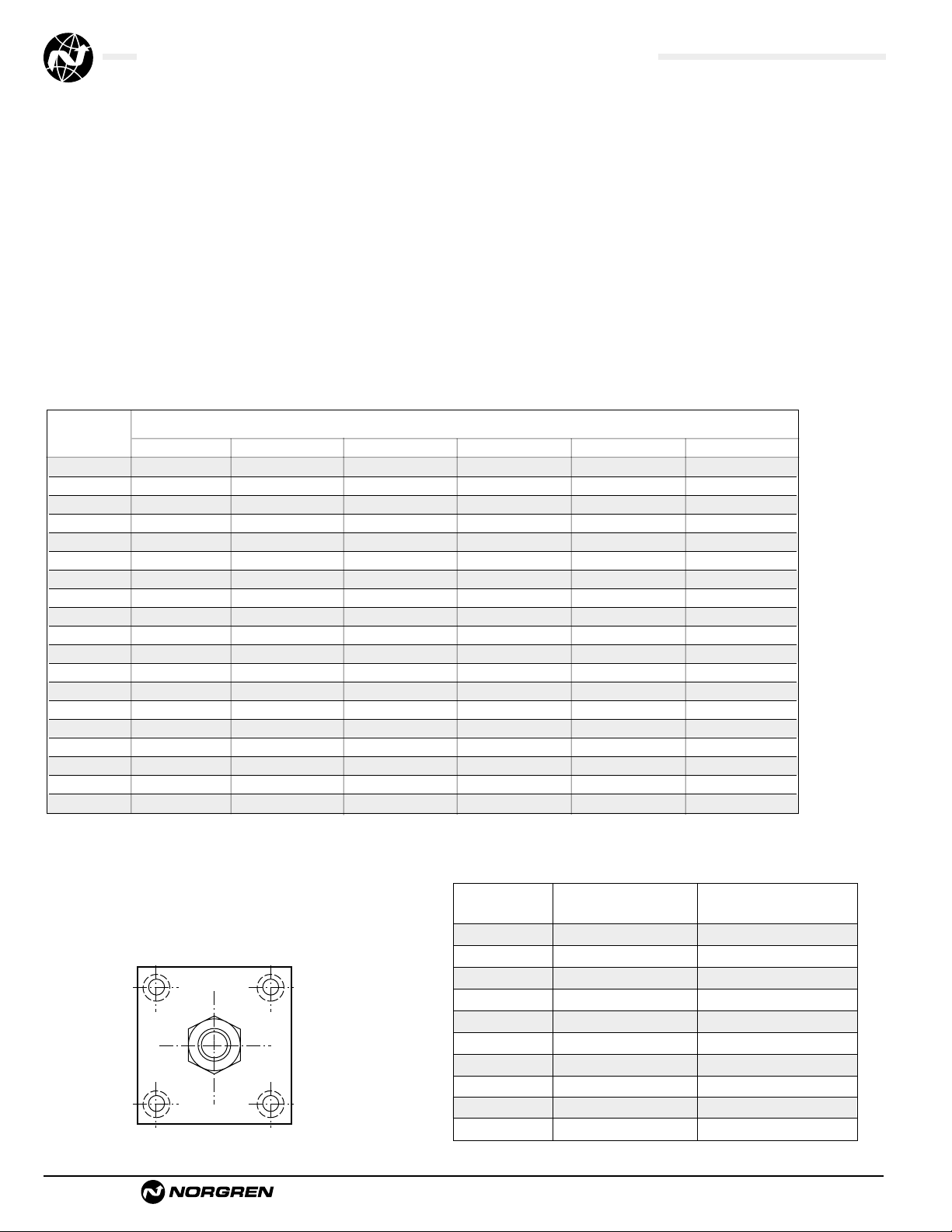
Additional Options – order alphabetically – More on page ACT-1-95
HR Case Hardened (45 Rc)
L(
_ _
) Port Location position 1 standard: L(Head
Cap)
(specify position 1 thru 4 for head and/or cap)
MS Metal Rod Scraper
N(
_ _
) Cushion Adjust Screw Location position 2 standard: N(Head
Cap) (specify position 1 thru 4 for head and/or cap)
P(_)* Non-Standard Port Sizes: [specify port size for P(_H) head
only, P(_C) cap only, or P(_) both head & cap]
PS Magnetic Piston – includes aluminum tube option for J & EJ - Std. for Alum
RS Rod Stud
Type 1 (5/8" – 1
3
/4" øRod)
Type 2 (5/8" & 1" øRod)
RX Rod Extensions (specify length of additional rod extension)
SC Single Acting Spring Extend (Cap End)–See page ACT-1-86
SR Single Acting Spring Retract (Rod End)–See page ACT-1-86
SS 303 Stainless Steel (Hard Chrome Plated)
ST(_C) Stop Tube (Cap End) (specify stop tube length
)
ST(_R) Stop Tube (Rod End) (specify stop tube length
)
T Special Rod Threads (specify rod thread)
TK Thrust Key
TX Thread Extensions (specify length of thread extension)
V Viton
®
Seals
*11/2", 2", 21/2" bore cylinders have 3/8" NPT Standard, 1/2" NPT oversize.
3
1
/4", 4", 5" bore cylinders have 1/2" NPT Standard, 3/4" NPT oversize.
This will add
1
/8" to the overall cylinder length.
Cylinder Order Information
01
–
–
–
–
Bore and Stroke (write out )
Piston Rod Diameters
A**
5
/8" Standard on 11/2", 2", 21/2"
Standard on 3
1
/4", 4", 5"
B** 1"
Oversized on 1
1
/2", 2", 21/2"
Standard on 6", 7", 8"
C** 1
3
/8"
Oversized on 3
1
/4", 4", 5"
Standard on 10"
D** 1
3
/4"
Oversized on 6", 7", 8"
Standard on 12"
E2"
Oversized on 10"
F2
1
/2" Oversized on 10", 12"
†
Standard with EA & EJ
†
Standard with EA & EJ
Cushion in Head
3 None
5†Non-Adjustable Cushion
7 Adjustable Cushion (Position 2)
9 Decel Cushion
Cushion in Cap
3 None
5
†
Non-Adjustable Cushion
7 Adjustable Cushion (Position 2)
9 Decel Cushion
Piston Rod Threads Type
1 Small Male (Solid)
2 Intermediate Thread Male (Solid)
3 Female
6 Full Thread Male (Solid)
7 Plain Rod End
** A & EA uses A-D only.
A Series A Cylinder
EA Series EA Cylinder
J Series J Cylinder
EJ Series EJ Cylinder
Mounting Options
01 Side Tapped (MS4)
03 Head Rectangular Flange (MF1)
03 Head Square (ME3)–7" to 12" Bores
04 Cap Rectangular Flange (MF2)
04 Cap Square (ME4)–7" to 12" Bores
05 Basic Cylinder No Mounting (MX0)
06 Both Ends (4) Tie Rods Ext. (MX1)
6B Both Ends (2) Tie Rods Ext. (MX4)
6C Cap Tie Rods Ext. (MX2)
6R Head Tie Rods Ext. (MX3)
7R Removable Head Trunion (MT1) - A & EA
07 Head Trunnion (MT1) - J & EJ
8R Cap Trunion (MT2) - A & EA
08 Cap Trunnion (MT2( - J & EJ
09 Side Lugs (MS2)
10 Center Trunnion (MT4)
11 Side End Angles (MS1)
12 Cap Fixed Clevis (MP1)
15 Side End Lugs (MS7)
16 Sleeve Nut Construction (Universal)
20 Head Square Flange (MF5)
21 Cap Square Flange (MF6)
22 Detachable Cap Clevis (MP2)
32 Cap Fixed Eye (MP3)
42 Detachable Cap Eye (MP4)
52 Spherical Bearing
60 Base Bar (Not NFPA - A & EA Only)
1
42
3
Page 19
Brookville, OH USA Phone 937-833-4033 www.norgren.com
ACT-1-19
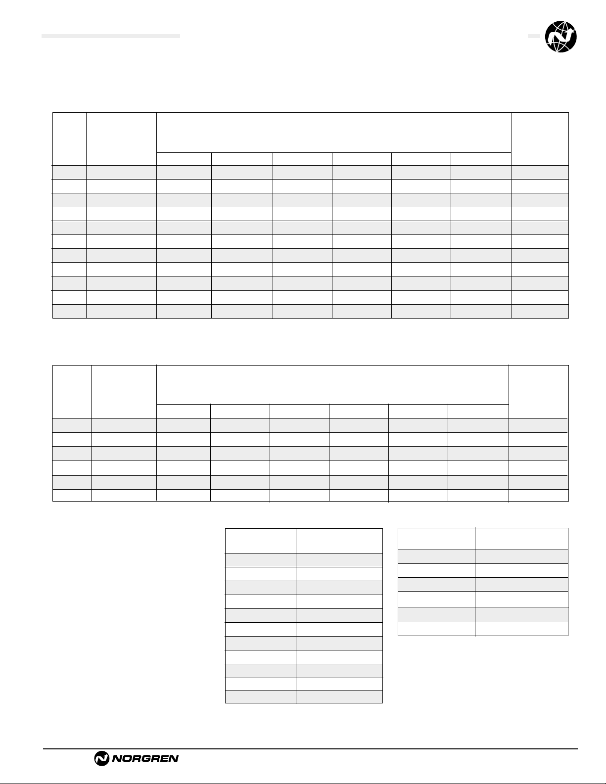
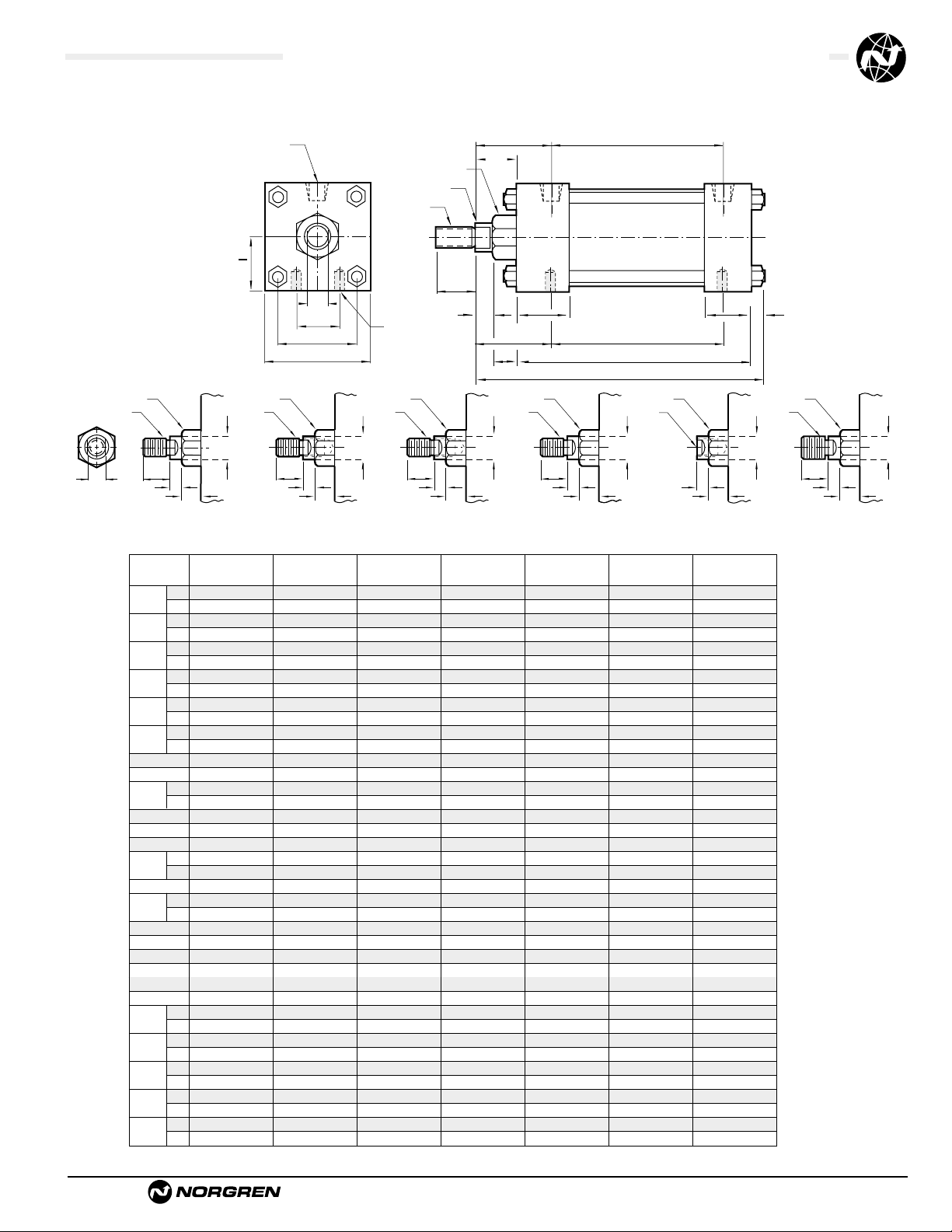
Series A & EA, NFPA Aluminum Air Cylinders with 01 (MS4) Side Tapped
Series J & EJ, NFPA Steel Air Cylinders with 01 (MS4) Side Tapped
All Dimensions in Inches (mm)
Standard &
Optional Rod Ends
D
(Flats)
EE NPT (2)
R
E Sq.
A
C
G
ZB + Stroke
LB + Stroke
J
K
P + StrokeY
øB Bushing
øMM
KK
Thds
WF
NT Tap
ND Deep
TN
SN + Stroke
XT
VF
E
2
.5/8" .5/8" .5/8" .1" .1" .1" 1.3/8"1.3/8"1.3/8"
.1" .1" .1" 1.
3
/8"1.3/8"1.3/8"1.3/4"1.3/4"1.3/4"
.750 .750 .750 1.125 1.125 1.125 1.625 1.625 1.625
1.125 1.125 1.125 1.625 1.625 1.625 2.000 2.000 2.000
1.124 1.124 1.124 1.499 1.499 1.499 1.999 1.999 1.999
1.499 1.499 1.499 1.999 1.999 1.999 2.374 2.374 2.374
.375 .375 .375 .500 .500 .500 .625 .625 .625
.500 .500 .500 .625 .625 .625 .750 .750 .750
.500 .500 .500 .813 .813 .813 1.125 1.125 1.125
.813 .813 .813 1.125 1.125 1.125 1.500 1.500 1.500
2.000 2.500 3.000 3.750 4.500 5.500 6.500 7.500 8.500
.375 .375 .375 .500 .500 .500 .750 .750 .750
1.500 1.500 1.500 1.750 1.750 1.750 2.000 2.000 2.000
1.000 1.000 1.000 1.250 1.250 1.250 1.500 1.500 1.500
.250 .313 .313 .375 .375 .438 .438 .563 .563
3.625 3.625 3.750 4.250 4.250 4.500 5.000 5.125 5.125
.625 .625 .625 1.000 1.000 1.000 1.375 1.375 1.375
1.000 1.000 1.000 1.375 1.375 1.375 1.750 1.750 1.750
.375 .375 .500 .750 .750 .938 1.125 1.125 1.125
2.340 2.340 2.470 2.690 2.690 2.940 3.125 3.250 3.250
1.428 1.838 2.192 2.758 3.323 4.101 4.879 5.730 6.442
2.250 2.250 2.375 2.625 2.625 2.875 3.125 3.250 3.250
.625 .875 1.250 1.500 2.063 2.688 3.250 3.500 4.500
.625 .625 .625 .875 .875 .875 1.000 1.000 1.000
.875 .875 .875 1.000 1.000 1.000 1.125 1.125 1.125
1.000 1.000 1.000 1.375 1.375 1.375 1.625 1.625 1.625
1.375 1.375 1.375 1.625 1.625 1.625 1.875 1.875 1.875
1.938 1.938 1.938 2.438 2.438 2.438 2.813 2.813 2.813
2.313 2.313 2.313 2.688 2.688 2.688 3.063 3.063 3.063
1.840 1.840 1.840 2.380 2.380 2.380 2.813 2.813 2.813
2.220 2.220 2.220 2.630 2.630 2.630 3.063 3.063 3.063
4.875 4.938 5.063 6.000 6.000 6.313 7.063 7.313 7.313
5.250 5.313 5.438 6.250 6.250 6.563 7.313 7.563 7.563
Dimension 1
1
/
2
" Bore (38.10) 2" Bore (50.80) 2
1
/
2
" Bore (63.50) 3
1
/
4
" Bore (82.55) 4" Bore (101.60) 5" Bore (127.00) 6" Bore (152.40) 7" Bore (177.80) 8" Bore (203.20)
ø Rod
Std.
O.S.
A
Std.
O.S.
B
+.000 Std.
-.002 O.S.
C
Std.
O.S.
CC
Std. 1/2 – 20 1/2 – 20 1/2 – 20 7/8 – 14 7/8 – 14 7/8 – 14 1
1
/4 – 12 11/4 – 12 11/4 – 12
O.S. 7/8 – 14 7/8 – 14 7/8 – 14 11/4 – 12 11/4 – 12 11/4 – 12 11/2 – 12 11/2 – 12 11/2 – 12
D
Std.
O.S.
E
EE
FF
Std. 5/8 – 18 5/8 – 18 5/8 – 18 1 – 14 1 – 14 1 – 14 1
3
/8 – 12 13/8 – 12 13/8 – 12
O.S. 1 – 14 1 – 14 1 – 14 1
3
/8 – 12 13/8 – 12 13/8 – 12 13/4 – 12 13/4 – 12 13/4 – 12
G
J
K
KK
Std. 7/16 – 20 7/16 – 20 7/16 – 20 3/4 – 16 3/4 – 16 3/4 – 16 1 – 14 1 – 14 1 – 14
O.S. 3/4 – 16 3/4 – 16 3/4 – 16 1 – 14 1 – 14 1 – 14 1
1
/4 – 12 11/4 – 12 11/4 – 12
LB
MM
Std.
O.S.
ND
NT 1/4 – 20 5/16 – 18 3/8 – 16 1/2 – 13 1/2 – 13 5/8 – 11 3/4 – 10 3/4 – 10 3/4 – 10
P
R
SN
TN
VF
Std.
O.S.
WF
Std.
O.S.
XT
Std.
O.S.
Y
Std.
O.S.
ZB
Std.
O.S.
(15.88) (15.88) (15.88) (25.40) (25.40) (25.40) (34.93) (34.93) (34.93)
(25.40) (25.40) (25.40) (34.93) (34.93) (34.93) (44.45) (44.45) (44.45)
(19.05) (19.05) (19.05) (28.58) (28.58) (28.58) (41.28) (41.28) (41.28)
(28.58) (28.58) (28.58) (41.28) (41.28) (41.28) (50.80) (50.80) (50.80)
(28.55) (28.55) (28.55) (38.08) (38.08) (38.08) (50.78) (50.78) (50.78)
(38.08) (38.08) (38.08) (50.78) (50.78) (50.78) (60.30) (60.30) (60.30)
(9.53) (9.53) (9.53) (12.70) (12.70) (12.70) (15.88) (15.88) (15.88)
(12.70) (12.70) (12.70) (15.88) (15.88) (15.88) (19.05) (19.05) (19.05)
(12.70) (12.70) (12.70) (20.64) (20.64) (20.64) (28.58) (28.58) (28.58)
(20.64) (20.64) (20.64) (28.58) (28.58) (28.58) (38.10) (38.10) (38.10)
(50.80) (63.50) (76.20) (95.25) (114.30) (139.70) (165.10) (190.50) (215.90)
(9.53) (9.53) (9.53) (12.70) (12.70) (12.70) (19.05) (19.05) (19.05)
(38.10) (38.10) (38.10) (44.45) (44.45) (44.45) (50.80) (50.80) (50.80)
(25.40) (25.40) (25.40) (31.75) (31.75) (31.75) (38.10) (38.10) (38.10)
(6.35) (7.94) (7.94) (9.53) (9.53) (11.11) (11.11) (14.29) (14.29)
(92.08) (92.08) (95.25) (107.95) (107.95) (114.30) (127.00) (130.18) (130.18)
(15.88) (15.88) (15.88) (25.40) (25.40) (25.40) (34.93) (34.93) (34.93)
(25.40) (25.40) (25.40) (34.93) (34.93) (34.93) (44.45) (44.45) (44.45)
(9.53) (9.53) (12.70) (19.05) (19.05) (23.81) (28.58) (28.58) (28.58)
(59.44) (59.44) (62.74) (68.33) (68.33) (74.68) (79.38) (82.55) (82.55)
(36.27) (46.68) (55.67) (70.05) (84.40) (104.16) (123.92) (145.54) (163.63)
(57.15) (57.15) (60.33) (66.68) (66.68) (73.03) (79.38) (82.55) (82.55)
(15.88) (22.23) (31.75) (38.10) (52.37) (68.28) (82.55) (88.90) (114.30)
(15.88) (15.88) (15.88) (22.23) (22.23) (22.23) (25.40) (25.40) (25.40)
(22.23) (22.23) (22.23) (25.40) (25.40) (25.40) (28.58) (28.58) (28.58)
(25.40) (25.40) (25.40) (34.93) (34.93) (34.93) (41.28) (41.28) (41.28)
(34.93) (34.93) (34.93) (41.28) (41.28) (41.28) (47.63) (47.63) (47.63)
(49.21) (49.21) (49.21) (61.91) (61.91) (61.91) (71.44) (71.44) (71.44)
(58.74) (58.74) (58.74) (68.26) (68.26) (68.26) (77.79) (77.79) (77.79)
(46.74) (46.74) (46.74) (60.45) (60.45) (60.45) (71.44) (71.44) (71.44)
(56.39) (56.39) (56.39) (66.80) (66.80) (66.80) (77.79) (77.79) (77.79)
(123.83) (125.41) (128.59) (152.40) (152.40) (160.34) (179.39) (185.74) (185.74)
(133.35) (134.94) (138.11) (158.75) (158.75) (166.69) (185.74) (192.10) (192.10)
ø B
KK
Thds.
A
C
VF
Type 1 Solid
(Small Male)
Across
D
Flats
ø B
KK
Thds.
øMM
A
Type 1 Studded
(Studded Male Optional)
øMM
C
VF
ø B
CC
Thds.
A
Type 2 Studded
(Intermediate Thread
ø B
CC
Thds.
øMM
A
C
VF
Type 2 Solid
Male Optional)
(Intermediate Thread
Male Optional)
øMM
C
VF
ø B
KK
Thds.
A Deep
Type 3 Female
ø B
FF
Thds.
øMM
A
C
VF
(Optional)
C
VF
Type 6 Solid
(Full Thread
Male Optional)
øMM
Page 20

ACT-1-20
Brookville, OH USA Phone 937-833-4033 www.norgren.com
Series A & EA, NFPA Aluminum Air Cylinders (ø1-1/2 to 8")
Series J & EJ, NFPA Steel Air Cylinders (ø1-1/2 to 12")
● NFPA (MS4) 01 Side Tapped Mount
for 7" to 12" bore sizes.
● Series A & J Cylinders rated to 250 PSI air,
400 PSI hydraulic (non-shock).
Series EA & EJ Cylinders rated to 250 PSI air only.
● Designed for non-lube service.
● Switches available on all bore sizes.
(See pages ACT-1-90 & 91 for ordering information.)
Cylinder with 01 (MS4) Sided Tapped
See page ACT-1-96 for complete
instructions on how to order cylinders.
1
3
42
Port and Cushion Adjustment
Positions (As viewed from rod end:
Port standard position 1, Cushion
Adjustment standard position 2.)
NOTE: A Port and a Cushion Adjustment
cannot be in the same position.
*11/2", 2", 21/2" bore cylinders have 3/8" NPT Standard, 1/2" NPT oversize.
3
1
/4", 4", 5" bore cylinders have 1/2" NPT Standard, 3/4" NPT oversize.
This will add
1
/8" to the overall cylinder length.
Cylinder Order Information
01
–
–
–
–
Bore and Stroke (write out )
Piston Rod Diameters
A**
5
/8" Standard on 11/2", 2", 21/2"
Standard on 3
1
/4", 4", 5"
B** 1"
Oversized on 1
1
/2", 2", 21/2"
Standard on 6", 7", 8"
C** 1
3
/8"
Oversized on 3
1
/4", 4", 5"
Standard on 10"
D** 1
3
/4"
Oversized on 6", 7", 8"
Standard on 12"
E2"
Oversized on 10"
F2
1
/2" Oversized on 10", 12"
A Series A Cylinder
EA Series EA Cylinder
J Series J Cylinder
EJ Series EJ Cylinder
Piston Rod Threads Type
1 Small Male (Solid)
2 Intermediate Thread Male (Solid)
3 Female
6 Full Thread Male (Solid)
7 Plain Rod End
** A & EA uses A-D only.
Additional Options – order alphabetically – More on page ACT-1-95
HR Case Hardened (45 Rc)
L(
_ _
) Port Location position 1 standard: L(Head
Cap)
(specify position 1 thru 4 for head and/or cap)
MS Metal Rod Scraper
N(
_ _
) Cushion Adjust Screw Location position 2 standard: N(Head
Cap) (specify position 1 thru 4 for head and/or cap)
P(_)* Non-Standard Port Sizes: [specify port size for P(_H) head
only, P(_C) cap only, or P(_) both head & cap]
PS Magnetic Piston – includes aluminum tube option for J & EJ - Std. for Alum
RS Rod Stud
Type 1 (5/8" – 1
3
/4" øRod)
Type 2 (5/8" & 1" øRod)
RX Rod Extensions (specify length of additional rod extension)
SC Single Acting Spring Extend (Cap End)–See page ACT-1-86
SR Single Acting Spring Retract (Rod End)–See page ACT-1-86
SS 303 Stainless Steel (Hard Chrome Plated)
ST(_C) Stop Tube (Cap End) (specify stop tube length
)
ST(_R) Stop Tube (Rod End) (specify stop tube length
)
T Special Rod Threads (specify rod thread)
TK Thrust Key
TX Thread Extensions (specify length of thread extension)
V Viton
®
Seals
Mounting Options
01 Side Tapped (MS4)
03 Head Rectangular Flange (MF1)
03 Head Square (ME3)–7" to 12" Bores
04 Cap Rectangular Flange (MF2)
04 Cap Square (ME4)–7" to 12" Bores
05 Basic Cylinder No Mounting (MX0)
06 Both Ends (4) Tie Rods Ext. (MX1)
6B Both Ends (2) Tie Rods Ext. (MX4)
6C Cap Tie Rods Ext. (MX2)
6R Head Tie Rods Ext. (MX3)
7R Removable Head Trunion (MT1) - A & EA
07 Head Trunnion (MT1) - J & EJ
8R Cap Trunion (MT2) - A & EA
08 Cap Trunnion (MT2( - J & EJ
09 Side Lugs (MS2)
10 Center Trunnion (MT4)
11 Side End Angles (MS1)
12 Cap Fixed Clevis (MP1)
15 Side End Lugs (MS7)
16 Sleeve Nut Construction (Universal)
20 Head Square Flange (MF5)
21 Cap Square Flange (MF6)
22 Detachable Cap Clevis (MP2)
32 Cap Fixed Eye (MP3)
42 Detachable Cap Eye (MP4)
52 Spherical Bearing
60 Base Bar (Not NFPA - A & EA Only)
†
Standard with EA & EJ
†
Standard with EA & EJ
Cushion in Head
3 None
5†Non-Adjustable Cushion
7 Adjustable Cushion (Position 2)
9 Decel Cushion
Cushion in Cap
3 None
5
†
Non-Adjustable Cushion
7 Adjustable Cushion (Position 2)
9 Decel Cushion
Page 21
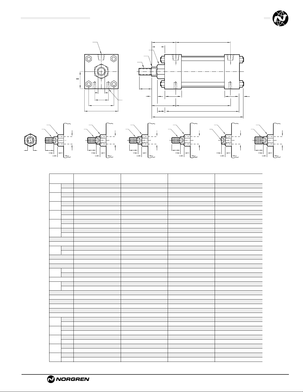
Brookville, OH USA Phone 937-833-4033 www.norgren.com
ACT-1-21
Series A & EA, NFPA Aluminum Air Cylinders with 01 (MS4) Side Tapped
Series J & EJ, NFPA Steel Air Cylinders with 01 (MS4) Side Tapped
All Dimensions in Inches (mm)
(34.93) (34.93) (44.45) (50.80)
(44.45) (44.45) (50.80) (63.50)
(41.28) (41.28) (50.80) (57.15)
(50.80) (50.80) (57.15) (76.20)
(50.78) (50.78) (60.30) (66.65)
(60.30) (60.30) (66.65) (79.35)
(15.88) (15.88) (19.05) (22.23)
(19.05) (19.05) (22.23) (25.40)
(28.58) (28.58) (38.10) (42.86)
(38.10) (38.10) (42.86) (52.39)
(190.50) (215.90) (269.88) (323.85)
(19.05) (19.05) (25.40) (25.40)
(50.80) (50.80) (57.15) (57.15)
(38.10) (38.10) (50.80) (50.80)
(14.29) (14.29) (17.46) (17.46)
(130.18) (130.18) (161.93) (174.63)
(34.93) (34.93) (44.45) (50.80)
(44.45) (44.45) (50.80) (63.50)
(28.58) (28.58) (38.10) (38.10)
(82.55) (82.55) (104.78) (117.48)
(145.54) (163.63) (202.41) (238.92)
(82.55) (82.55) (104.78) (117.48)
(88.90) (114.30) (139.70) (184.15)
(25.40) (25.40) (28.58) (28.58)
(28.58) (28.58) (28.58) (31.75)
(41.28) (41.28) (47.63) (50.80)
(47.63) (47.63) (50.80) (57.15)
(71.44) (71.44) (79.38) (82.55)
(77.79) (77.79) (82.55) (88.90)
(71.44) (71.44) (79.38) (82.55)
(77.79) (77.79) (82.55) (88.90)
(185.74) (185.74) (227.01) (242.89)
(192.10) (192.10) (230.19) (249.24)
1.
3
/8"1.3/8"1.3/4" .2"
1.
3
/4"1.3/4" .2" 2.1/2"
1.625 1.625 2.000 2.250
2.000 2.000 2.250 3.000
1.999 1.999 2.374 2.624
2.374 2.374 2.624 3.124
.625 .625 .750 .875
.750 .750 .875 1.000
1.125 1.125 1.500 1.688
1.500 1.500 1.688 2.063
7.500 8.500 10.625 12.750
.750 .750 1.000 1.000
2.000 2.000 2.250 2.250
1.500 1.500 2.000 2.000
.563 .563 .688 .688
5.125 5.125 6.375 6.875
1.375 1.375 1.750 2.000
1.750 1.750 2.000 2.500
1.125 1.125 1.500 1.500
3.250 3.250 4.125 4.625
5.730 6.442 7.969 9.406
3.250 3.250 4.125 4.625
3.500 4.500 5.500 7.250
1.000 1.000 1.125 1.125
1.125 1.125 1.125 1.250
1.625 1.625 1.875 2.000
1.875 1.875 2.000 2.250
2.813 2.813 3.125 3.250
3.063 3.063 3.250 3.500
2.813 2.813 3.125 3.250
3.063 3.063 3.250 3.500
7.313 7.313 8.938 9.563
7.563 7.563 9.063 9.813
Dimension 7" Bore (177.80) 8" Bore (203.20) 10" Bore (254.00) 12" Bore (304.80)
ø Rod
Std.
O.S.
A
Std.
O.S.
B
+.000 Std.
-.002 O.S.
C
Std.
O.S.
CC
Std. 1
1
/4 – 12 11/4 – 12 11/2 – 12 13/4 – 12
O.S. 11/2 – 12 11/2 – 12 13/4 – 12 21/4 – 12
D
Std.
O.S.
E
EE
FF
Std. 1
3
/8 – 12 13/8 – 12 13/4 – 12 2 – 12
O.S. 1
3
/4 – 12 13/4 – 12 2 – 12 21/2 – 12
G
J
K
KK
Std. 1 – 14 1 – 14 1
1
/4 – 12 11/2 – 12
O.S. 1
1
/4 – 12 11/4 – 12 11/2 – 12 17/8 – 12
LB
MM
Std.
O.S.
ND
NT 3/4 – 10 3/4 – 10 1 – 8 1 – 8
P
R
SN
TN
VF
Std.
O.S.
WF
Std.
O.S.
XT
Std.
O.S.
Y
Std.
O.S.
ZB
Std.
O.S.
Standard &
Optional Rod Ends
D
(Flats)
EE NPT (2)
R
E Sq.
A
C
G
ZB + Stroke
LB + Stroke
J
K
P + StrokeY
øB Bushing
øMM
KK
Thds
WF
NT Tap
ND Deep
TN
SN + Stroke
XT
VF
E
2
Across
Flats
ø B
KK
Thds.
øMM
D
A
C
VF
Type 1 Solid
(Small Male)
ø B
KK
Thds.
øMM
A
C
VF
Type 1 Studded
(Studded Male Optional)
ø B
CC
Thds.
A
Type 2 Studded
(Intermediate Thread
øMM
C
VF
Male Optional)
ø B
CC
Thds.
A
C
VF
Type 2 Solid
(Intermediate Thread
Male Optional)
øMM
ø B
KK
Thds.
A Deep
Type 3 Female
C
VF
(Optional)
øMM
FF
Thds.
ø B
A
C
VF
Type 6 Solid
(Full Thread
Male Optional)
øMM
Page 22
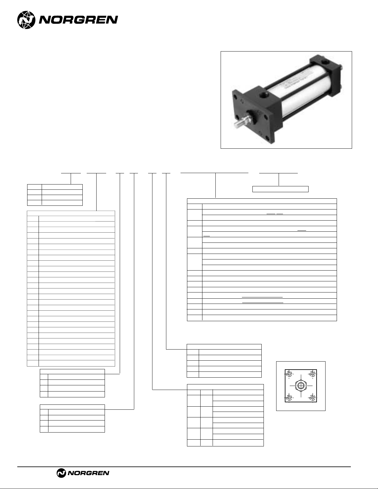
ACT-1-22
Brookville, OH USA Phone 937-833-4033 www.norgren.com
Series A & EA, NFPA Aluminum Air Cylinders (ø1-1/2 to 6")
Series J & EJ, NFPA Steel Air Cylinders (ø1-1/2 to 6")
● NFPA (MF1) 03 Head Rectangular Flange Mount
for 1-1/2" to 6" bore sizes.
● Series A & J Cylinders rated to 250 PSI air,
400 PSI hydraulic (non-shock).
Series EA & EJ Cylinders rated to 250 PSI air only.
● Designed for non-lube service.
● Switches available on all bore sizes.
(See pages ACT-1-90 & 91 for ordering information.)
Cylinder with 03 (MF1) Head Rectangular Flange
See page ACT-1-96 for complete
instructions on how to order cylinders.
Port and Cushion Adjustment
Positions
(As viewed from rod end:
Port standard position 1, Cushion
Adjustment standard position 2.)
NOTE: A Port and a Cushion Adjustment
cannot be in the same position.
*11/2", 2", 21/2" bore cylinders have 3/8" NPT Standard, 1/2" NPT oversize.
3
1
/4", 4", 5" bore cylinders have 1/2" NPT Standard, 3/4" NPT oversize.
This will add
1
/8" to the overall cylinder length.
A Series A Cylinder
EA Series EA Cylinder
J Series J Cylinder
EJ Series EJ Cylinder
Cylinder Order Information
03
–
–
–
–
Bore and Stroke (write out )
Piston Rod Diameters
A**
5
/8" Standard on 11/2", 2", 21/2"
Standard on 3
1
/4", 4", 5"
B** 1"
Oversized on 1
1
/2", 2", 21/2"
Standard on 6", 7", 8"
C** 1
3
/8"
Oversized on 3
1
/4", 4", 5"
Standard on 10"
D** 1
3
/4"
Oversized on 6", 7", 8"
Standard on 12"
E2"
Oversized on 10"
F2
1
/2" Oversized on 10", 12"
Piston Rod Threads Type
1 Small Male (Solid)
2 Intermediate Thread Male (Solid)
3 Female
6 Full Thread Male (Solid)
7 Plain Rod End
** A & EA uses A-D only.
Additional Options – order alphabetically – More on page ACT-1-95
HR Case Hardened (45 Rc)
L(
_ _
) Port Location position 1 standard: L(Head Cap)
(specify position 1 thru 4 for head and/or cap)
MS Metal Rod Scraper
N(
_ _
) Cushion Adjust Screw Location position 2 standard: N(Head
Cap) (specify position 1 thru 4 for head and/or cap)
P(_)* Non-Standard Port Sizes: [specify port size for P(_H) head
only, P(_C) cap only, or P(_) both head & cap]
PS Magnetic Piston – includes aluminum tube option for J & EJ - Std. for Alum
RS Rod Stud
Type 1 (5/8" – 1
3
/4" øRod)
Type 2 (5/8" & 1" øRod)
RX Rod Extensions (specify length of additional rod extension)
SC Single Acting Spring Extend (Cap End)–See page ACT-1-86
SR Single Acting Spring Retract (Rod End)–See page ACT-1-86
SS 303 Stainless Steel (Hard Chrome Plated)
ST(_C) Stop Tube (Cap End) (specify stop tube length
)
ST(_R) Stop Tube (Rod End) (specify stop tube length
)
T Special Rod Threads (specify rod thread)
TX Thread Extensions (specify length of thread extension)
V Viton
®
Seals
Mounting Options
01 Side Tapped (MS4)
03 Head Rectangular Flange (MF1)
03 Head Square (ME3)–7" to 12" Bores
04 Cap Rectangular Flange (MF2)
04 Cap Square (ME4)–7" to 12" Bores
05 Basic Cylinder No Mounting (MX0)
06 Both Ends (4) Tie Rods Ext. (MX1)
6B Both Ends (2) Tie Rods Ext. (MX4)
6C Cap Tie Rods Ext. (MX2)
6R Head Tie Rods Ext. (MX3)
7R Removable Head Trunion (MT1) - A & EA
07 Head Trunnion (MT1) - J & EJ
8R Cap Trunion (MT2) - A & EA
08 Cap Trunnion (MT2( - J & EJ
09 Side Lugs (MS2)
10 Center Trunnion (MT4)
11 Side End Angles (MS1)
12 Cap Fixed Clevis (MP1)
15 Side End Lugs (MS7)
16 Sleeve Nut Construction (Universal)
20 Head Square Flange (MF5)
21 Cap Square Flange (MF6)
22 Detachable Cap Clevis (MP2)
32 Cap Fixed Eye (MP3)
42 Detachable Cap Eye (MP4)
52 Spherical Bearing
60 Base Bar (Not NFPA - A & EA Only)
†
Standard with EA & EJ
†
Standard with EA & EJ
Cushion in Head
3 None
5†Non-Adjustable Cushion
7 Adjustable Cushion (Position 2)
9 Decel Cushion
Cushion in Cap
3 None
5
†
Non-Adjustable Cushion
7 Adjustable Cushion (Position 2)
9 Decel Cushion
42
1
3
Page 23
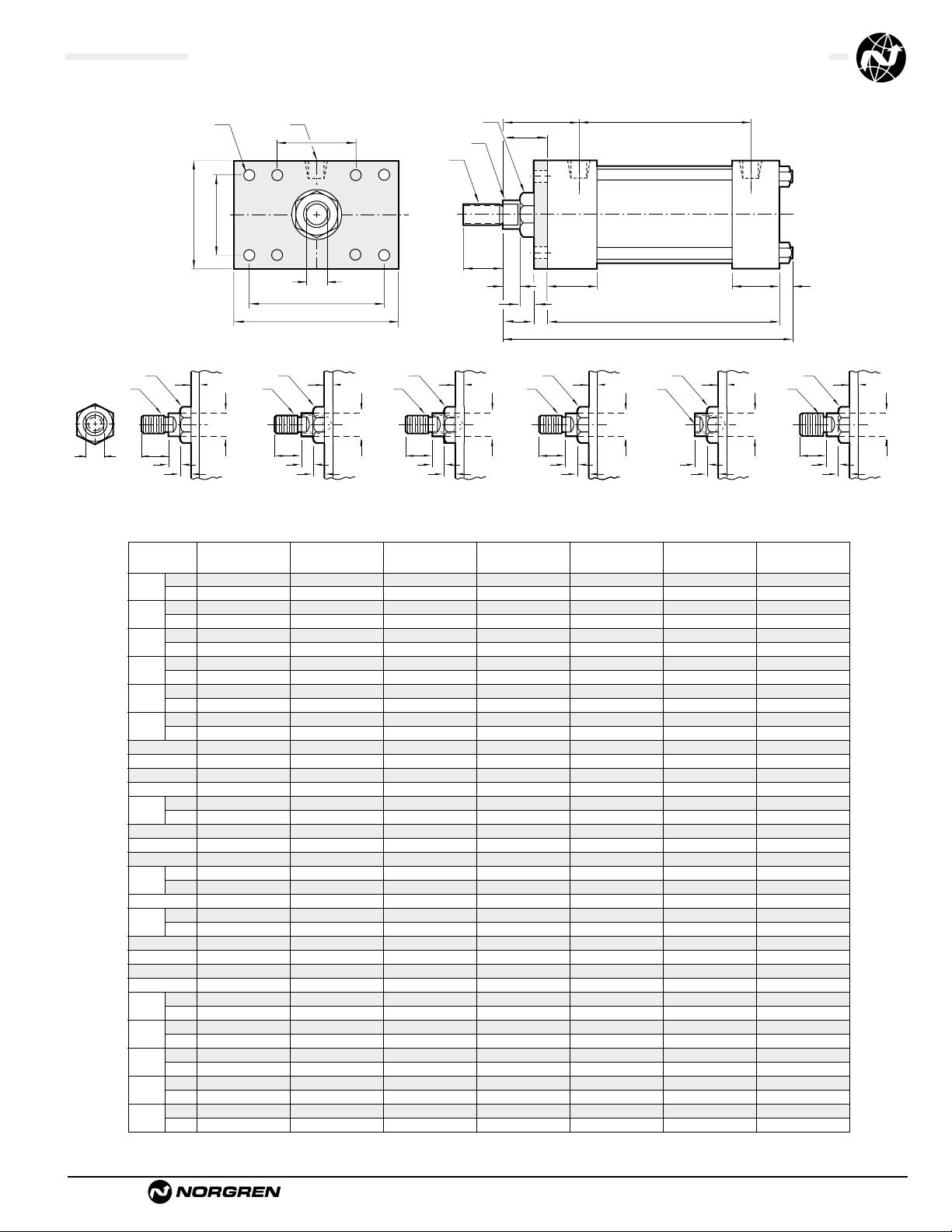
Brookville, OH USA Phone 937-833-4033 www.norgren.com
ACT-1-23
Series A & EA, NFPA Aluminum Air Cylinders with 03 (MF1) Head Rectangular Flange
Series J & EJ, NFPA Steel Air Cylinders with 03 (MF1) Head Rectangular Flange
All Dimensions in Inches (mm)
Standard &
Optional Rod Ends
R
C
V
G
ZB + Stroke
LB + Stroke
J
K
P + StrokeY
øB Bushing
øMM
KK
Thds
EE NPT(2)FB Holes (4)
E
D
(Flats)
TF
UF
F
A
W
WF
R
Dimension 1
1
/
2
" Bore (38.10) 2" Bore (50.80) 2
1
/
2
" Bore (63.50) 3
1
/
4
" Bore (82.55) 4" Bore (101.60) 5" Bore (127.00) 6" Bore (152.40) 8" Bore (203.20)
ø Rod
Std.
O.S.
A
Std.
O.S.
B
+.000 Std.
-.002 O.S.
C
Std.
O.S.
CC
Std. 1/2 – 20 1/2 – 20 1/2 – 20 7/8 – 14 7/8 – 14 7/8 – 14 1
1
/4 – 12 11/4 – 12
O.S. 7/8 – 14 7/8 – 14 7/8 – 14 1
1
/4 – 12 11/4 – 12 11/4 – 12 11/2 – 12 11/2 – 12
D
Std.
O.S.
E
EE
F –
FB
FF
Std. 5/8 – 18 5/8 – 18 5/8 – 18 1 – 14 1 – 14 1 – 14 1
3
/8 – 12 13/8 – 12
O.S. 1 – 14 1 – 14 1 – 14 1
3
/8 – 12 13/8 – 12 13/8 – 12 13/4 – 12 13/4 – 12
G
J
K
KK
Std. 7/16 – 20 7/16 – 20 7/16 – 20 3/4 – 16 3/4 – 16 3/4 – 16 1 – 14 1 – 14
O.S. 3/4 –16 3/4 –16 3/4 –16 1 – 14 1 – 14 1 – 14 1
1
/4 – 12 11/4 – 12
LB
MM
Std.
O.S.
P
R
TF –
UF –
V
Std.
O.S.
W
Std.
O.S.
WF
Std. –
O.S. –
Y
Std.
O.S.
ZB
Std.
O.S.
(15.88) (15.88) (15.88) (25.40) (25.40) (25.40) (34.93) (34.93)
(25.40) (25.40) (25.40) (34.93) (34.93) (34.93) (44.45) (44.45)
(19.05) (19.05) (19.05) (28.58) (28.58) (28.58) (41.28) (41.28)
(28.58) (28.58) (28.58) (41.28) (41.28) (41.28) (50.80) (50.80)
(28.55) (28.55) (28.55) (38.08) (38.08) (38.08) (50.78) (50.78)
(38.08) (38.08) (50.78) (50.78) (50.78) (60.30) (60.30) (60.30)
(9.53) (9.53) (9.53) (12.70) (12.70) (12.70) (15.88) (15.88)
(12.70) (12.70) (12.70) (15.88) (15.88) (15.88) (19.05) (19.05)
(12.70) (12.70) (12.70) (20.64) (20.64) (20.64) (28.58) (28.58)
(20.64) (20.64) (20.64) (28.58) (28.58) (28.58) (38.10) (38.10)
(50.80) (63.50) (76.20) (95.25) (114.30) (139.70) (165.10) (215.90)
(9.53) (9.53) (9.53) (12.70) (12.70) (12.70) (19.05) (19.05)
(9.53) (9.53) (9.53) (15.88) (15.88) (15.88) (19.05)
(7.94) (9.53) (9.53) (11.11) (11.11) (14.29) (14.29) (17.45)
(38.10) (38.10) (38.10) (44.45) (44.45) (44.45) (50.80) (50.80)
(25.40) (25.40) (25.40) (31.75) (31.75) (31.75) (38.10) (38.10)
(6.35) (7.94) (7.94) (9.53) (9.53) (11.11) (11.11) (14.29)
(92.08) (92.08) (95.25) (107.95) (107.95) (114.30) (127.00) (130.18)
(15.88) (15.88) (15.88) (25.40) (25.40) (25.40) (34.93) (34.42)
(25.40) (25.40) (25.40) (34.93) (34.93) (34.93) (44.45) (43.94)
(59.44) (59.44) (62.74) (68.33) (68.33) (74.68) (79.38) (79.38)
(36.27) (46.68) (55.67) (70.05) (84.40) (104.16) (123.92) (163.44)
(69.85) (85.73) (98.43) (119.06) (138.11) (168.28) (193.68)
(85.73) (104.78) (117.48) (139.70) (158.75) (193.68) (219.08)
(6.35) (6.35) (6.35) (6.35) (6.35) (6.35) (6.35) (9.53)
(12.70) (12.70) (12.70) (9.53) (9.53) (9.53) (9.53) (9.53)
(15.88) (15.88) (15.88) (19.05) (19.05) (19.05) (22.23) (41.28)
(25.40) (25.40) (25.40) (25.40) (25.40) (25.40) (28.58) (47.63)
(25.40) (25.40) (25.40) (34.93) (34.93) (34.93) (41.27)
(34.93) (34.93) (34.93) (41.27) (41.27) (41.27) (47.63)
(46.74) (46.74) (46.74) (60.45) (60.45) (60.45) (71.44) (71.44)
(56.39) (56.39) (56.39) (66.80) (66.80) (66.80) (77.79) (77.79)
(123.83) (125.41) (128.59) (152.40) (152.40) (160.34) (179.39) (185.74)
(133.35) (134.94) (138.11) (158.75) (158.75) (166.69) (185.74) (193.68)
.5/8" .5/8" .5/8" .1" .1" .1" 1.
3
/8"1.3/8"
.1" .1" .1" 1.
3
/8"1.3/8"1.3/8"1.3/4"1.3/4"
.750 .750 .750 1.125 1.125 1.125 1.625 1.625
1.125 1.125 1.125 1.625 1.625 1.625 2.000 2.000
1.124 1.124 1.124 1.499 1.499 1.499 1.999 1.999
1.499 1.499 1.499 1.999 1.999 1.999 2.374 2.374
.375 .375 .375 .500 .500 .500 .625 .625
.500 .500 .500 .625 .625 .625 .750 .750
.500 .500 .500 .813 .813 .813 1.125 1.125
.813 .813 .813 1.125 1.125 1.125 1.500 1.500
2.000 2.500 3.000 3.750 4.500 5.500 6.500 8.500
.375 .375 .375 .500 .500 .500 .750 .750
.375 .375 .375 .625 .625 .625 .750
.313 .375 .375 .438 .438 .563 .563 .687
1.500 1.500 1.500 1.750 1.750 1.750 2.000 2.000
1.000 1.000 1.000 1.250 1.250 1.250 1.500 1.500
.250 .313 .313 .375 .375 .438 .438 .563
3.625 3.625 3.750 4.250 4.250 4.500 5.000 5.125
.625 .625 .625 1.000 1.000 1.000 1.375 1.355
1.000 1.000 1.000 1.375 1.375 1.375 1.750 1.730
2.340 2.340 2.470 2.690 2.690 2.940 3.125 3.250
1.428 1.838 2.192 2.758 3.323 4.101 4.879 6.435
2.750 3.375 3.875 4.688 5.438 6.625 7.625
3.375 4.125 4.625 5.500 6.250 7.625 8.625
.250 .250 .250 .250 .250 .250 .250 .375
.500 .500 .500 .375 .375 .375 .375 .375
.625 .625 .625 .750 .750 .750 .875 1.625
1.000 1.000 1.000 1.000 1.000 1.000 1.125 1.875
1.000 1.000 1.000 1.375 1.375 1.375 1.625
1.375 1.375 1.375 1.625 1.625 1.625 1.875
1.840 1.840 1.840 2.380 2.380 2.380 2.813 2.813
2.220 2.220 2.220 2.630 2.630 2.688 3.063 3.063
4.875 4.938 5.063 6.000 6.000 6.630 7.063 7.313
5.250 5.313 5.438 6.250 6.250 6.563 7.313 7.625
ø B
KK
Thds.
D
Across
Flats
A
Type 1 Solid
F
øMM
C
V
(Small Male)
øB
KK
Thds.
A
Type 1 Studded
(Studded Male Optional)
F
øMM
C
V
øB
CC
Thds.
A
Type 2 Studded
(Intermediate Thread
Male Optional)
F
øMM
C
V
øB
CC
Thds.
A
Type 2 Solid
(Intermediate Thread
Male Optional)
F
C
V
øMM
øB
KK
Thds.
A Deep
Type 3 Female
C
V
(Optional)
F
øMM
øB
FF
Thds.
A
C
V
Type 6 Solid
(Full Thread
Male Optional)
F
øMM
Page 24
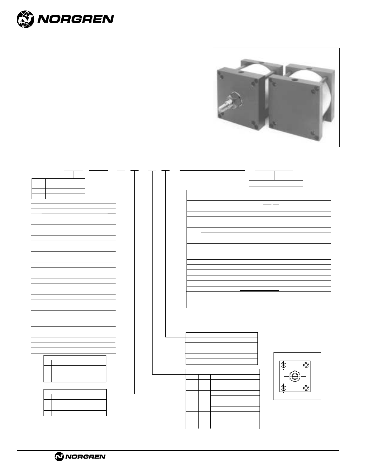
ACT-1-24
Brookville, OH USA Phone 937-833-4033 www.norgren.com
Series A & EA, NFPA Aluminum Air Cylinders (ø7" & 8")
Series J & EJ, NFPA Steel Air Cylinders (ø7" to 12")
● NFPA (ME3) 03 Head Square Mount and
NFPA (ME4) 04 Cap Square Mount
for 7" to 12" bore sizes only.
● Series A & J Cylinders rated to 250 PSI air,
400 PSI hydraulic (non-shock).
Series EA & EJ Cylinders rated to 250 PSI air only.
● Designed for non-lube service.
● Switches available on all bore sizes.
(See pages ACT-1-90 & 91 for ordering information.)
Cylinder with 03 (ME3) Head Square
and Cylinder with 04 (ME4) Cap Square
Port and Cushion Adjustment
Positions (As viewed from rod end:
Port standard position 1, Cushion
Adjustment standard position 2.)
NOTE: A Port and a Cushion Adjustment
cannot be in the same position.
*11/2", 2", 21/2" bore cylinders have 3/8" NPT Standard, 1/2" NPT oversize.
3
1
/4", 4", 5" bore cylinders have 1/2" NPT Standard, 3/4" NPT oversize.
This will add
1
/8" to the overall cylinder length.
Cylinder Order Information
03
04
–
–
–
–
Bore and Stroke (write out )
Piston Rod Diameters
A**
5
/8" Standard on 11/2", 2", 21/2"
Standard on 3
1
/4", 4", 5"
B** 1"
Oversized on 1
1
/2", 2", 21/2"
Standard on 6", 7", 8"
C** 1
3
/8"
Oversized on 3
1
/4", 4", 5"
Standard on 10"
D** 1
3
/4"
Oversized on 6", 7", 8"
Standard on 12"
E2"
Oversized on 10"
F2
1
/2" Oversized on 10", 12"
Piston Rod Threads Type
1 Small Male (Solid)
2 Intermediate Thread Male (Solid)
3 Female
6 Full Thread Male (Solid)
7 Plain Rod End
A Series A Cylinder
EA Series EA Cylinder
J Series J Cylinder
EJ Series EJ Cylinder
Additional Options – order alphabetically – More on page ACT-1-95
HR Case Hardened (45 Rc)
L(
_ _
) Port Location position 1 standard: L(Head
Cap)
(specify position 1 thru 4 for head and/or cap)
MS Metal Rod Scraper
N(
_ _
) Cushion Adjust Screw Location position 2 standard: N(Head
Cap) (specify position 1 thru 4 for head and/or cap)
P(_)* Non-Standard Port Sizes: [specify port size for P(_H) head
only, P(_C) cap only, or P(_) both head & cap]
PS Magnetic Piston – includes aluminum tube option for J & EJ - Std. for Alum
RS Rod Stud
Type 1 (5/8" – 1
3
/4" øRod)
Type 2 (5/8" & 1" øRod)
RX Rod Extensions (specify length of additional rod extension)
SC Single Acting Spring Extend (Cap End)–See page ACT-1-86
SR Single Acting Spring Retract (Rod End)–See page ACT-1-86
SS 303 Stainless Steel (Hard Chrome Plated)
ST(_C) Stop Tube (Cap End) (specify stop tube length
)
ST(_R) Stop Tube (Rod End) (specify stop tube length
)
T Special Rod Threads (specify rod thread)
TX Thread Extensions (specify length of thread extension)
V Viton
®
Seals
Mounting Options
01 Side Tapped (MS4)
03 Head Rectangular Flange (MF1)
03 Head Square (ME3)–7" to 12" Bores
04 Cap Rectangular Flange (MF2)
04 Cap Square (ME4)–7" to 12" Bores
05 Basic Cylinder No Mounting (MX0)
06 Both Ends (4) Tie Rods Ext. (MX1)
6B Both Ends (2) Tie Rods Ext. (MX4)
6C Cap Tie Rods Ext. (MX2)
6R Head Tie Rods Ext. (MX3)
7R Removable Head Trunion (MT1) - A & EA
07 Head Trunnion (MT1) - J & EJ
8R Cap Trunion (MT2) - A & EA
08 Cap Trunnion (MT2( - J & EJ
09 Side Lugs (MS2)
10 Center Trunnion (MT4)
11 Side End Angles (MS1)
12 Cap Fixed Clevis (MP1)
15 Side End Lugs (MS7)
16 Sleeve Nut Construction (Universal)
20 Head Square Flange (MF5)
21 Cap Square Flange (MF6)
22 Detachable Cap Clevis (MP2)
32 Cap Fixed Eye (MP3)
42 Detachable Cap Eye (MP4)
52 Spherical Bearing
60 Base Bar (Not NFPA - A & EA Only)
†
Standard with EA & EJ
†
Standard with EA & EJ
Cushion in Head
3 None
5†Non-Adjustable Cushion
7 Adjustable Cushion (Position 2)
9 Decel Cushion
Cushion in Cap
3 None
5
†
Non-Adjustable Cushion
7 Adjustable Cushion (Position 2)
9 Decel Cushion
1
42
3
Page 25
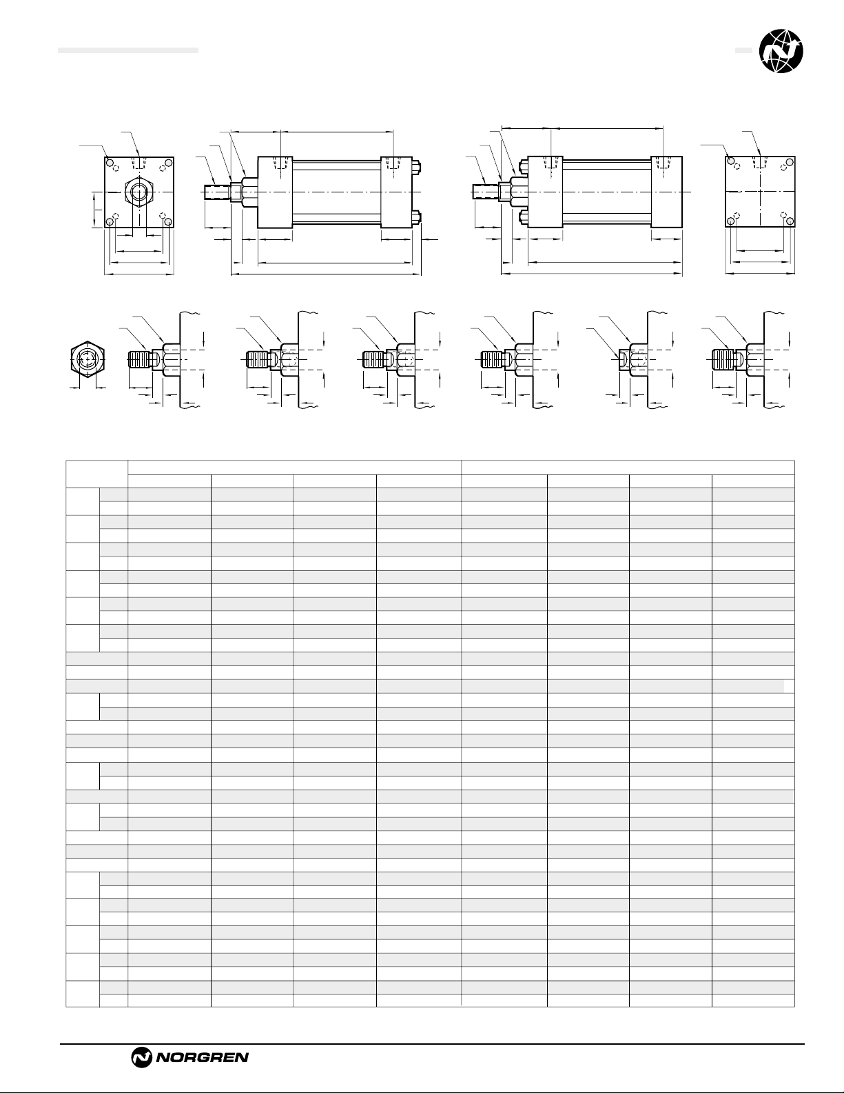
Brookville, OH USA Phone 937-833-4033 www.norgren.com
ACT-1-25
Series A & EA Cylinder with 03 (ME3) Head Square & 04 (ME4) Cap Square
Series J & EJ NFPA Cylinder with 03 (ME3) Head Square & 04 (ME4) Cap Square
All Dimensions in Inches (mm)
(34.93) (34.93) (44.45) (50.80) (34.93) (34.93) (44.45) (50.80)
(44.45) (44.45) (50.80) (63.50) (44.45) (44.45) (50.80) (63.50)
(41.28) (41.28) (50.80) (57.15) (41.28) (41.28) (50.80) (57.15)
(50.80) (50.80) (57.15) (76.20) (50.80) (50.80) (57.15) (76.20)
(50.78) (50.78) (60.30) (66.65) (50.78) (50.78) (60.30) (66.65)
(60.30) (60.30) (66.65) (79.35) (60.30) (60.30) (66.65) (79.35)
(15.88) (15.88) (19.05) (22.23) (15.88) (15.88) (19.05) (22.23)
(19.05) (19.05) (22.23) (25.40) (19.05) (19.05) (22.23) (25.40)
(28.58) (28.58) (38.10) (42.86) (28.58) (28.58) (38.10 (42.86)
(38.10) (38.10) (42.86) (52.39) (38.10) (38.10) (42.86) (52.39)
(190.50) (215.90) (269.88) (323.85) (190.50) (215.90) (269.88) (323.85)
(14.29) (17.46) (20.64) (20.64) (14.29) (17.46) (20.64) (20.64)
(19.05) (19.05) (25.40) (25.40) (19.05) (19.05) (25.40) (25.40)
(50.80) (50.80) (57.15) (57.15) (50.80) (50.80) (57.15) (57.15)
(38.10) (38.10) (50.80) (50.80) (38.10) (38.10) (50.80) (50.80)
(14.29) (14.29) (17.46) (17.46) (14.29) (14.29) (17.46) (17.46)
(130.18) (130.18) (161.93) (174.63) (130.18) (130.18) (161.93) (174.63)
(34.93) (34.93) (44.45) (50.80) (34.93) (34.93) (44.45) (50.80)
(44.45) (44.45) (50.80) (63.50) (44.45) (44.45) (50.80) (63.50)
(82.55) (82.55) (104.78) (117.48) (82.55) (82.55) (104.78) (117.48)
(145.54) (163.63) (202.41) (238.92) (145.54) (163.63) (202.41) (238.92)
(171.45) (192.27) (238.92) (282.18) (171.45) (192.27) (238.92) (282.18)
(25.40) (25.40) (28.58) (28.58) (25.40) (25.40) (28.58) (28.58)
(28.58) (28.58) (28.58) (31.75) (28.58) (28.58) (28.58) (31.75)
(41.28) (41.28) (47.63) (50.80) (41.28) (41.28) (47.63) (50.80)
(47.63) (47.63) (50.80) (57.15) (47.63) (47.63) (50.80) (57.15)
(71.44) (71.44) (79.38) (82.55) (71.44) (71.44) (79.38) (82.55)
(77.79) (77.79) (82.55) (88.90) (77.79) (77.79) (82.55) (88.90)
(185.74) (185.74) (227.01) (242.89)
(192.09) (192.09) (230.19) (249.24)
(171.45) (171.45) (209.55) (225.43)
(177.80) (177.80) (212.73) (231.78)
1.
3
/8"1.3/8"1.3/4" .2" 1.3/8"1.3/8"1.3/4" .2"
1.
3
/4"1.3/4" .2" 2.1/2"1.3/4"1.3/4" .2" 2.1/2"
1.625 1.625 2.000 2.250 1.625 1.625 2.000 2.250
2.000 2.000 2.250 3.000 2.000 2.000 2.250 3.000
1.999 1.999 2.374 2.624 1.999 1.999 2.374 2.624
2.374 2.374 2.624 3.124 2.374 2.374 2.624 3.124
.625 .625 .750 .875 .625 .625 .750 .875
.750 .750 .875 1.000 .750 .750 .875 1.000
1.125 1.125 1.500 1.688 1.125 1.125 1.500 1.688
1.500 1.500 1.688 2.063 1.500 1.500 1.688 2.063
7.500 8.500 10.625 12.750 7.500 8.500 10.625 12.750
.563 .688 .813 .813 .563 .688 .813 .813
.750 .750 1.000 1.000 .750 .750 1.000 1.000
2.000 2.000 2.250 2.250 2.000 2.000 2.250 2.250
1.500 1.500 2.000 2.000 1.500 1.500 2.000 2.000
.563 .563 .688 .688 .563 .563 .688 .688
5.125 5.125 6.375 6.875 5.125 5.125 6.375 6.875
1.375 1.375 1.750 2.000 1.375 1.375 1.750 2.000
1.750 1.750 2.000 2.500 1.750 1.750 2.000 2.500
3.250 3.250 4.125 4.625 3.250 3.250 4.125 4.625
5.730 6.442 7.969 9.406 5.730 6.442 7.969 9.406
6.750 7.570 9.406 11.109 6.750 7.570 9.406 11.109
1.000 1.000 1.125 1.125 1.000 1.000 1.125 1.125
1.125 1.125 1.125 1.250 1.125 1.125 1.125 1.250
1.625 1.625 1.875 2.000 1.625 1.625 1.875 2.000
1.875 1.875 2.000 2.250 1.875 1.875 2.000 2.250
2.813 2.813 3.125 3.250 2.813 2.813 3.125 3.250
3.063 3.063 3.250 3.500 3.063 3.063 3.250 3.500
7.313 7.313 8.938 9.563
7.563 7.563 9.063 9.813
6.750 6.750 8.250 8.875
7.000 7.000 8.375 9.125
03 (ME3) Head Square 04 (ME4) Cap Square
Dimension 7" Bore (177.80) 8" Bore (203.20) 10" Bore (254.00) 12" Bore (304.80) 7" Bore (177.80) 8" Bore (203.20) 10" Bore (254.00) 12" Bore (304.80)
ø Rod
Std.
O.S.
A
Std.
O.S.
B
+.000 Std.
-.002 O.S.
C
Std.
O.S.
CC
Std. 1
1
/4 – 12 11/4 – 12 11/2 – 12 13/4 – 12 11/4 – 12 11/4 – 12 11/2 – 12 13/4 – 12
O.S. 1
1
/2 – 12 11/2 – 12 13/4 – 12 21/4 – 12 11/2 – 12 11/2 – 12 13/4 – 12 21/4 – 12
D
Std.
O.S.
E
EB
EE
FF
Std. 1
3
/8 – 12 13/8 – 12 13/4 – 12 2 – 12 13/8 – 12 13/8 – 12 13/4 – 12 2 – 12
O.S. 1
3
/4 – 12 13/4 – 12 2 – 12 21/2 – 12 13/4 – 12 13/4 – 12 2 – 12 21/2 – 12
G
J
K
KK
Std. 1 – 14 1 – 14 1
1
/4 – 12 11/2 – 12 1 – 14 1 – 14 11/4 – 12 11/2 – 12
O.S. 1
1
/4 – 12 11/4 – 12 11/2 – 12 17/8 – 12 11/4 – 12 11/4 – 12 11/2 – 12 17/8 – 12
LB
MM
Std.
O.S.
P
R
TE
VF
Std.
O.S.
WF
Std.
O.S.
Y
Std.
O.S.
ZB
Std. ––––
O.S. ––––
ZJ
Std. – – – –
O.S. – – – –
Standard & Optional Rod Ends
04 (ME4) 03 (ME3)
EE NPT (2)
EB
Holes (4)
øB Bushing
øMM
KK
Thds
E
2
D
(Flats)
R
TE
E Sq.
Y
A
C
VF
ø B
KK
Thds.
A
Type 1 Studded
(Studded Male Optional)
D
Across
Flats
KK
Thds.
ø B
øMM
A
C
VF
Type 1 Solid
(Small Male)
P + Stroke
G
LB + Stroke
ZB + Stroke
ø B
CC
Thds.
øMM
C
VF
J
A
C
VF
Type 2 Studded
(Intermediate Thread
Male Optional)
K
øMM
øB Bushing
øMM
KK
Thds
ø B
CC
Thds.
A
A
Type 2 Solid
(Intermediate Thread
Male Optional)
G
C
VF
øMM
C
VF
P + StrokeY
LB + Stroke
ZJ + Stroke
ø B
KK
Thds.
A Deep
Type 3 Female
C
VF
(Optional)
øMM
J
EE NPT (2)
EB
Holes (4)
ø B
FF
Thds.
R
TE
E
A
C
VF
Type 6 Solid
(Full Thread
Male Optional)
øMM
Page 26
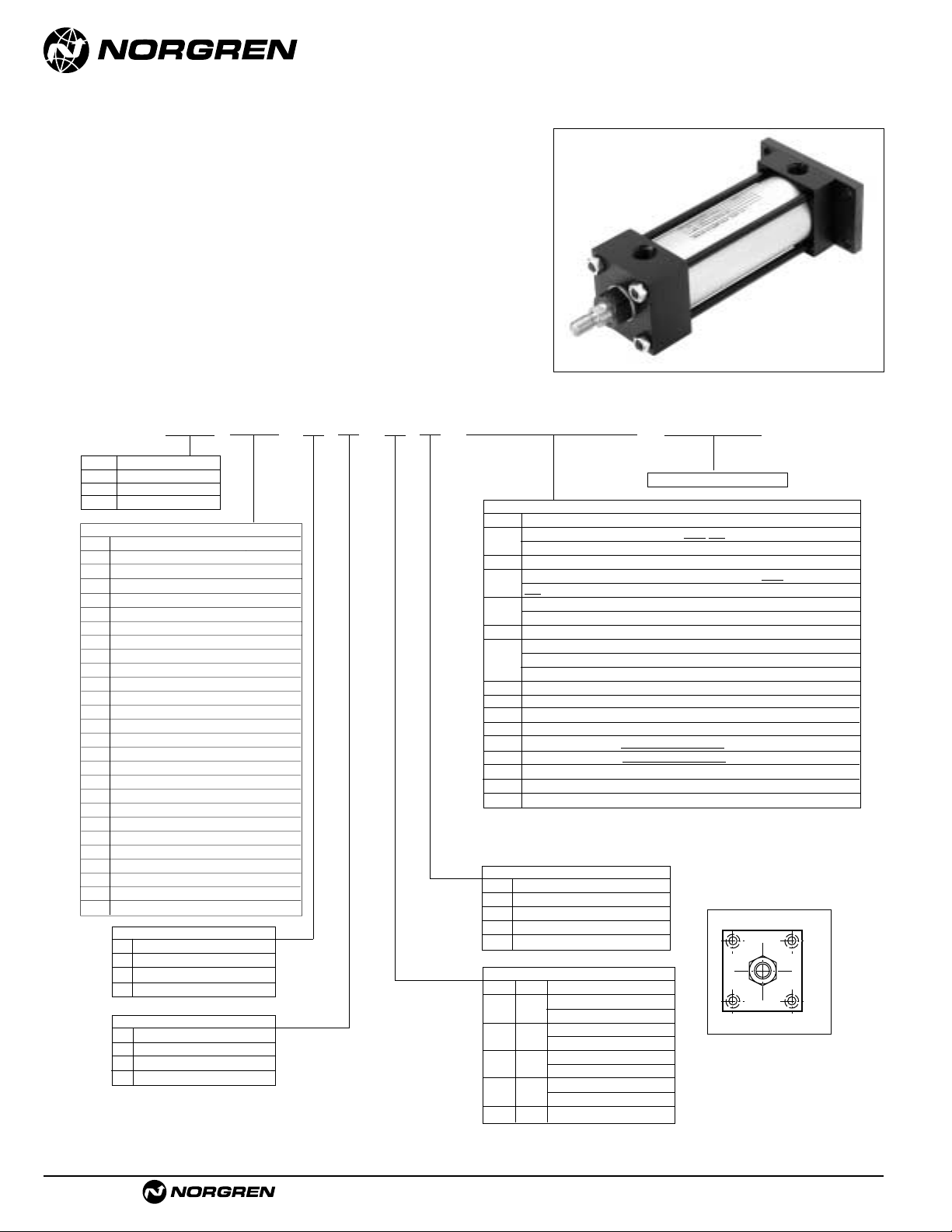
ACT-1-26
Brookville, OH USA Phone 937-833-4033 www.norgren.com
Series A & EA, NFPA Aluminum Air Cylinders (ø1-1/2 to 6")
Series J & EJ, NFPA Steel Air Cylinders (ø1-1/2 to 6")
● NFPA (MF2) 04 Cap Rectangular Flange Mount
for 1-1/2" to 6" bore sizes.
● Series A & J Cylinders rated to 250 PSI air,
400 PSI hydraulic (non-shock).
Series EA & EJ Cylinders rated to 250 PSI air only.
● Designed for non-lube service.
● Switches available on all bore sizes.
(See pages ACT-1-90 & 91 for ordering information.)
Cylinder with 04 (MF2) Cap Rectangular Flange
See page ACT-1-96 for complete
instructions on how to order cylinders.
Port and Cushion Adjustment
Positions (As viewed from rod end:
Port standard position 1, Cushion
Adjustment standard position 2.)
NOTE: A Port and a Cushion Adjustment
cannot be in the same position.
*11/2", 2", 21/2" bore cylinders have 3/8" NPT Standard, 1/2" NPT oversize.
3
1
/4", 4", 5" bore cylinders have 1/2" NPT Standard, 3/4" NPT oversize.
This will add
1
/8" to the overall cylinder length.
Cylinder Order Information
04
–
–
–
–
Bore and Stroke (write out )
Piston Rod Diameters
A**
5
/8" Standard on 11/2", 2", 21/2"
Standard on 3
1
/4", 4", 5"
B** 1"
Oversized on 1
1
/2", 2", 21/2"
Standard on 6", 7", 8"
C** 1
3
/8"
Oversized on 3
1
/4", 4", 5"
Standard on 10"
D** 1
3
/4"
Oversized on 6", 7", 8"
Standard on 12"
E2"
Oversized on 10"
F2
1
/2" Oversized on 10", 12"
Piston Rod Threads Type
1 Small Male (Solid)
2 Intermediate Thread Male (Solid)
3 Female
6 Full Thread Male (Solid)
7 Plain Rod End
A Series A Cylinder
EA Series EA Cylinder
J Series J Cylinder
EJ Series EJ Cylinder
Additional Options – order alphabetically – More on page ACT-1-95
HR Case Hardened (45 Rc)
L(
_ _
) Port Location position 1 standard: L(Head
Cap)
(specify position 1 thru 4 for head and/or cap)
MS Metal Rod Scraper
N(
_ _
) Cushion Adjust Screw Location position 2 standard: N(Head
Cap) (specify position 1 thru 4 for head and/or cap)
P(_)* Non-Standard Port Sizes: [specify port size for P(_H) head
only, P(_C) cap only, or P(_) both head & cap]
PS Magnetic Piston – includes aluminum tube option for J & EJ - Std. for Alum
RS Rod Stud
Type 1 (5/8" – 1
3
/
4" øRod)
Type 2 (5/8" & 1" øRod)
RX Rod Extensions (specify length of additional rod extension)
SC Single Acting Spring Extend (Cap End)–See page ACT-1-86
SR Single Acting Spring Retract (Rod End)–See page ACT-1-86
SS 303 Stainless Steel (Hard Chrome Plated)
ST(_C) Stop Tube (Cap End) (specify stop tube length
)
ST(_R) Stop Tube (Rod End) (specify stop tube length
)
T Special Rod Threads (specify rod thread)
TX Thread Extensions (specify length of thread extension)
V Viton
®
Seals
Mounting Options
01 Side Tapped (MS4)
03 Head Rectangular Flange (MF1)
03 Head Square (ME3)–7" to 12" Bores
04 Cap Rectangular Flange (MF2)
04 Cap Square (ME4)–7" to 12" Bores
05 Basic Cylinder No Mounting (MX0)
06 Both Ends (4) Tie Rods Ext. (MX1)
6B Both Ends (2) Tie Rods Ext. (MX4)
6C Cap Tie Rods Ext. (MX2)
6R Head Tie Rods Ext. (MX3)
7R Removable Head Trunion (MT1) - A & EA
07 Head Trunnion (MT1) - J & EJ
8R Cap Trunion (MT2) - A & EA
08 Cap Trunnion (MT2( - J & EJ
09 Side Lugs (MS2)
10 Center Trunnion (MT4)
11 Side End Angles (MS1)
12 Cap Fixed Clevis (MP1)
15 Side End Lugs (MS7)
16 Sleeve Nut Construction (Universal)
20 Head Square Flange (MF5)
21 Cap Square Flange (MF6)
22 Detachable Cap Clevis (MP2)
32 Cap Fixed Eye (MP3)
42 Detachable Cap Eye (MP4)
52 Spherical Bearing
60 Base Bar (Not NFPA - A & EA Only)
†
Standard with EA & EJ
†
Standard with EA & EJ
Cushion in Head
3 None
5†Non-Adjustable Cushion
7 Adjustable Cushion (Position 2)
9 Decel Cushion
Cushion in Cap
3 None
5
†
Non-Adjustable Cushion
7 Adjustable Cushion (Position 2)
9 Decel Cushion
1
42
3
Page 27
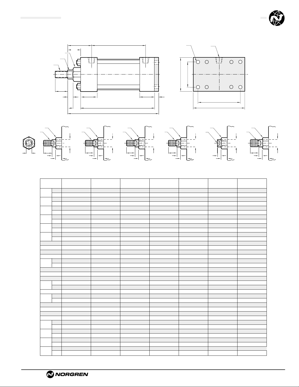
Brookville, OH USA Phone 937-833-4033 www.norgren.com
ACT-1-27
Series A & EA, NFPA Aluminum Air Cylinders with 04 (MF2) Cap Rectangular Flange
Series J & EJ, NFPA Steel Air Cylinders with 04 (MF2) Cap Rectangular Flange
All Dimensions in Inches (mm)
Standard & Optional Rod Ends
.5/8" .5/8" .5/8" .1" .1" .1" 1.3/8"1.3/8"
.1" .1" .1" 1.
3
/8"1.3/8"1.3/8"1.3/4"1.3/4"
.750 .750 .750 1.125 1.125 1.125 1.625 1.625
1.125 1.125 1.125 1.625 1.625 1.625 2.000 2.000
1.124 1.124 1.124 1.499 1.499 1.499 1.999 1.999
1.499 1.499 1.499 1.999 1.999 1.999 2.374 2.374
.375 .375 .375 .500 .500 .500 .625 .625
.500 .500 .500 .625 .625 .625 .750 .750
.500 .500 .500 .813 .813 .813 1.125 1.125
.813 .813 .813 1.125 1.125 1.125 1.500 1.500
2.000 2.500 3.000 3.750 4.500 5.500 6.500 8.500
.375 .375 .375 .500 .500 .500 .750 .750
.375 .375 .375 .625 .625 .625 .750
.313 .375 .375 .438 .438 .563 .563 .687
1.500 1.500 1.500 1.750 1.750 1.750 2.000 2.000
1.000 1.000 1.000 1.250 1.250 1.250 1.500 1.500
.250 .313 .313 .375 .375 .438 .438 .563
3.625 3.625 3.750 4.250 4.250 4.500 5.000 5.125
.625 .625 .625 1.000 1.000 1.000 1.375 1.355
1.000 1.000 1.000 1.375 1.375 1.375 1.750 1.730
2.340 2.340 2.470 2.690 2.690 2.940 3.125 3.250
1.428 1.838 2.192 2.758 3.323 4.101 4.879 6.435
2.750 3.375 3.875 4.687 5.438 6.625 7.625
3.375 4.125 4.625 5.500 6.250 7.625 8.625
.625 .625 .625 .875 .875 .875 1.000 1.000
.875 .875 .875 1.000 1.000 1.000 1.125 1.000
1.000 1.000 1.000 1.375 1.375 1.375 1.625
1.375 1.375 1.375 1.625 1.625 1.625 1.875
1.840 1.840 1.840 2.380 2.380 2.380 2.813 2.813
2.220 2.220 2.220 2.630 2.630 2.630 3.063 3.063
5.000 5.000 5.125 6.250 6.250 6.500 7.375 6.750
5.375 5.375 5.500 6.500 6.500 6.750 7.625 7.000
Dimension 1
1
/
2
" Bore (38.10) 2" Bore (50.80) 2
1
/
2
" Bore (63.50) 3
1
/
4
" Bore (82.55) 4" Bore (101.60) 5" Bore (127.00) 6" Bore (152.40) 8" Bore (203.20)
ø Rod
Std.
O.S.
A
Std.
O.S.
B
+.000 Std.
-.002 O.S.
C
Std.
O.S.
CC
Std. 1/2 – 20 1/2 – 20 1/2 – 20 7/8 –14 7/8 –14 7/8 –14 1
1
/4 – 12 11/4 – 12
O.S. 7/8 –14 7/8 –14 7/8 –14 1
1
/4 – 12 11/4 – 12 11/4 – 12 11/2 – 12 11/2 – 12
D
Std.
O.S.
E
EE
F
FB
FF
Std. 5/8 – 18 5/8 – 18 5/8 – 18 1 – 14 1 – 14 1 – 14 1
3
/8 – 12 13/8 – 12
O.S. 1 – 14 1 – 14 1 – 14 1
3
/8 – 12 13/8 – 12 13/8 – 12 13/4 – 12 13/4 – 12
G
J
K
KK
Std. 7/16 – 20 7/16 – 20 7/16 – 20 3/4 – 16 3/4 – 16 3/4 – 16 1 – 14 1 – 14
O.S. 3/4 – 16 3/4 – 16 3/4 – 16 1 – 14 1 – 14 1 – 14 1
1
/4 – 12 11/4 – 12
LB
MM
Std.
O.S.
P
R
TF –
UF –
VF
Std.
O.S.
WF
Std.
O.S.
Y
Std.
O.S.
ZF
Std.
O.S.
(15.88) (15.88) (15.88) (25.40) (25.40) (25.40) (34.93) (34.93)
(25.40) (25.40) (25.40) (34.93) (34.93) (34.93) (44.45) (44.45)
(19.05) (19.05) (19.05) (28.58) (28.58) (28.58) (41.28) (41.28)
(28.58) (28.58) (28.58) (41.28) (41.28) (41.28) (50.80) (50.80)
(28.55) (28.55) (28.55) (38.08) (38.08) (38.08) (50.78) (50.78)
(38.08) (38.08) (38.08) (50.78) (50.78) (50.78) (60.30) (60.30)
(9.53) (9.53) (9.53) (12.70) (12.70) (12.70) (15.88) (15.88)
(12.70) (12.70) (12.70) (15.88) (15.88) (15.88) (19.05) (19.05)
(12.70) (12.70) (12.70) (20.64) (20.64) (20.64) (28.58) (28.58)
(20.64) (20.64) (20.64) (28.58) (28.58) (28.58) (38.10) (38.10)
(50.80) (63.50) (76.20) (95.25) (114.30) (139.70) (165.10) (215.90)
(9.53) (9.53) (9.53) (12.70) (12.70) (12.70) (19.05) (19.05)
(9.53) (9.53) (9.53) (15.88) (15.88) (15.88) (19.05)
(7.94) (9.53) (9.53) (11.11) (11.11) (14.29) (14.29) (17.45)
(38.10) (38.10) (38.10) (44.45) (44.45) (44.45) (50.80) (50.80)
(25.40) (25.40) (25.40) (31.75) (31.75) (31.75) (38.10) (38.10)
(6.35) (7.94) (7.94) (9.53) (9.53) (11.11) (11.11) (14.29)
(92.08) (92.08) (95.25) (107.95) (107.95) (114.30) (127.00) (130.18)
(15.88) (15.88) (15.88) (25.40) (25.40) (25.40) (34.93) (34.42)
(25.40) (25.40) (25.40) (34.93) (34.93) (34.93) (44.45) (43.94)
(59.44) (59.44) (62.74) (68.33) (68.33) (74.68) (79.38) (82.55)
(36.27) (46.68) (55.67) (70.05) (84.40) (104.16) (123.93) (163.44)
(69.85) (85.73) (98.43) (119.05) (138.11) (168.28) (193.68)
(85.73) (104.78) (117.48) (139.70) (158.75) (193.68) (219.08)
(15.88) (15.88) (15.88) (22.23) (22.23) (22.23) (25.40) (9.53)
(22.23) (22.23) (22.23) (25.40) (25.40) (25.40) (28.58) (9.53)
(25.40) (25.40) (25.40) (34.93) (34.93) (34.93) (41.27)
(34.93) (34.93) (34.93) (41.27) (41.27) (41.27) (47.63)
(46.74) (46.74) (46.74) (60.45) (60.45) (60.45) (71.44) (71.44)
(56.39) (56.39) (56.39) (66.80) (66.80) (66.80) (77.79) (77.79)
(127.00) (127.00) (130.18) (158.75) (158.75) (165.10) (187.33) (171.45)
(136.53) (136.53) (139.70) (165.10) (165.10) (171.45) (193.68) (177.80)
øB Bushing
øMM
KK
Thds
WF
A
C
G
VF
ø B
KK
Thds.
A
C
VF
Type 1 Studded
(Studded Male Optional)
D
Across
Flats
ø B
KK
Thds.
øMM
A
C
VF
Type 1 Solid
(Small Male)
P + StrokeY
LB + Stroke
ZF + Stroke
CC
Thds.
øMM
J
ø B
A
C
VF
Type 2 Studded
(Intermediate Thread
Male Optional)
FB Holes (4) EE NPT (2)
RE
F
ø B
CC
Thds.
øMM
A
C
VF
Type 2 Solid
(Intermediate Thread
Male Optional)
øMM
KK
Thds.
A Deep
TF
UF
ø B
C
Type 3 Female
(Optional)
VF
øMM
ø B
FF
Thds.
A
C
VF
Type 6 Solid
(Full Thread
Male Optional)
øMM
Page 28

ACT-1-28
Brookville, OH USA Phone 937-833-4033 www.norgren.com
Series A & EA, NFPA Aluminum Air Cylinders (ø1-1/2 to 8")
Series J & EJ, NFPA Steel Air Cylinders (ø1-1/2 to 12")
● NFPA (MX0) 05 Basic Mount,
for 1-1/2" to 6" bore sizes.
● Series A & J Cylinders rated to 250 PSI air,
400 PSI hydraulic (non-shock).
Series EA & EJ Cylinders rated to 250 PSI air only.
● Designed for non-lube service.
● Switches available on all bore sizes.
(See pages ACT-1-90 & 91 for ordering information.)
Cylinder with 05 (MX0) Basic
See page ACT-1-96 for complete
instructions on how to order cylinders.
*11/2", 2", 21/2" bore cylinders have 3/8" NPT Standard, 1/2" NPT oversize.
3
1
/4", 4", 5" bore cylinders have 1/2" NPT Standard, 3/4" NPT oversize.
This will add
1
/8" to the overall cylinder length.
Cylinder Order Information
05
–
–
–
–
Bore and Stroke (write out )
Piston Rod Diameters
A**
5
/8" Standard on 11/2", 2", 21/2"
Standard on 3
1
/4", 4", 5"
B** 1"
Oversized on 1
1
/2", 2", 21/2"
Standard on 6", 7", 8"
C** 1
3
/8"
Oversized on 3
1
/4", 4", 5"
Standard on 10"
D** 1
3
/4"
Oversized on 6", 7", 8"
Standard on 12"
E2"
Oversized on 10"
F2
1
/2" Oversized on 10", 12"
1
3
42
Piston Rod Threads Type
1 Small Male (Solid)
2 Intermediate Thread Male (Solid)
3 Female
6 Full Thread Male (Solid)
7 Plain Rod End
Port and Cushion Adjustment
Positions (As viewed from rod end:
Port standard position 1, Cushion
Adjustment standard position 2.)
NOTE: A Port and a Cushion Adjustment
cannot be in the same position.
A Series A Cylinder
EA Series EA Cylinder
J Series J Cylinder
EJ Series EJ Cylinder
** A & EA uses A-D only.
Additional Options – order alphabetically – More on page ACT-1-95
HR Case Hardened (45 Rc)
L(
_ _
) Port Location position 1 standard: L(Head
Cap)
(specify position 1 thru 4 for head and/or cap)
MS Metal Rod Scraper
N(
_ _
) Cushion Adjust Screw Location position 2 standard: N(Head
Cap) (specify position 1 thru 4 for head and/or cap)
P(_)* Non-Standard Port Sizes: [specify port size for P(_H) head
only, P(_C) cap only, or P(_) both head & cap]
PS Magnetic Piston – includes aluminum tube option for J & EJ - Std. for Alum
RS Rod Stud
Type 1 (5/8" – 1
3
/4" øRod)
Type 2 (5/8" & 1" øRod)
RX Rod Extensions (specify length of additional rod extension)
SC Single Acting Spring Extend (Cap End)–See page ACT-1-86
SR Single Acting Spring Retract (Rod End)–See page ACT-1-86
SS 303 Stainless Steel (Hard Chrome Plated)
ST(_C) Stop Tube (Cap End) (specify stop tube length
)
ST(_R) Stop Tube (Rod End) (specify stop tube length
)
T Special Rod Threads (specify rod thread)
TX Thread Extensions (specify length of thread extension)
V Viton
®
Seals
Mounting Options
01 Side Tapped (MS4)
03 Head Rectangular Flange (MF1)
03 Head Square (ME3)–7" to 12" Bores
04 Cap Rectangular Flange (MF2)
04 Cap Square (ME4)–7" to 12" Bores
05 Basic Cylinder No Mounting (MX0)
06 Both Ends (4) Tie Rods Ext. (MX1)
6B Both Ends (2) Tie Rods Ext. (MX4)
6C Cap Tie Rods Ext. (MX2)
6R Head Tie Rods Ext. (MX3)
7R Removable Head Trunion (MT1) - A & EA
07 Head Trunnion (MT1) - J & EJ
8R Cap Trunion (MT2) - A & EA
08 Cap Trunnion (MT2( - J & EJ
09 Side Lugs (MS2)
10 Center Trunnion (MT4)
11 Side End Angles (MS1)
12 Cap Fixed Clevis (MP1)
15 Side End Lugs (MS7)
16 Sleeve Nut Construction (Universal)
20 Head Square Flange (MF5)
21 Cap Square Flange (MF6)
22 Detachable Cap Clevis (MP2)
32 Cap Fixed Eye (MP3)
42 Detachable Cap Eye (MP4)
52 Spherical Bearing
60 Base Bar (Not NFPA - A & EA Only)
†
Standard with EA & EJ
†
Standard with EA & EJ
Cushion in Head
3 None
5†Non-Adjustable Cushion
7 Adjustable Cushion (Position 2)
9 Decel Cushion
Cushion in Cap
3 None
5
†
Non-Adjustable Cushion
7 Adjustable Cushion (Position 2)
9 Decel Cushion
Page 29
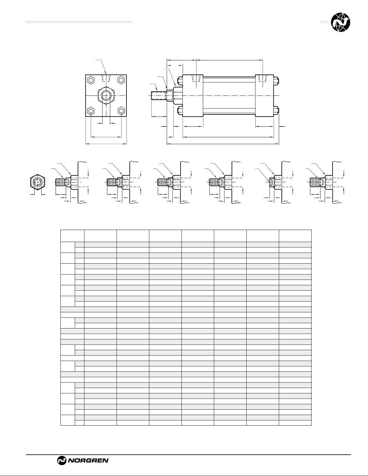
Brookville, OH USA Phone 937-833-4033 www.norgren.com
ACT-1-29
Series A & EA, NFPA Aluminum Air Cylinder with 05 (MX0) Basic
Series J & EJ, NFPA Steel Air Cylinder with 05 (MX0) Basic
All Dimensions in Inches (mm)
A
C
VF
G
ZB + Stroke
LB + Stroke
J
K
P + StrokeY
øB Bushing
øMM
KK
Thds
D
(Flats)
EE NPT (2)
R
E Sq.
WF
Standard & Optional Rod Ends
(15.88) (15.88) (15.88) (25.40) (25.40) (25.40) (34.93) (34.93) (34.
(25.40) (25.40) (25.40) (34.93) (34.93) (34.93) (44.45) (44.45) (44.
(19.05) (19.05) (19.05) (28.58) (28.58) (28.58) (41.28) (41.28) (41.
(28.58) (28.58) (28.58) (41.28) (41.28) (41.28) (50.80) (50.80) (50.
(28.55) (28.55) (28.55) (38.08) (38.08) (38.08) (50.78) (50.78) (50.
(38.08) (38.08) (38.08) (50.78) (50.78) (50.78) (60.30) (60.30) (60.
(9.53) (9.53) (9.53) (12.70) (12.70) (12.70) (15.88) (15.88) (15.
(12.70) (12.70) (12.70) (15.88) (15.88) (15.88) (19.05) (19.05) (19.
(12.70) (12.70) (12.70) (20.64) (20.64) (20.64) (28.58) (28.58) (28.
(20.64) (20.64) (20.64) (28.58) (28.58) (28.58) (38.10) (38.10) (38.
(50.80) (63.50) (76.20) (95.25) (114.30) (139.70) (165.10) (190.50) (215.
(9.53) (9.53) (9.53) (12.70) (12.70) (12.70) (19.05) (19.05) (19.
(38.10) (38.10) (38.10) (44.45) (44.45) (44.45) (50.80) (50.80) (50.
(25.40) (25.40) (25.40) (31.75) (31.75) (31.75) (38.10) (38.10) (38.
(6.35) (7.94) (7.94) (9.53) (9.53) (11.11) (11.11) (14.29) (14.
(92.08) (92.08) (95.25) (107.95) (107.95) (114.30) (127.00) (130.18) (130.
(15.88) (15.88) (15.88) (25.40) (25.40) (25.40) (34.93) (34.93) (34.
(25.40) (25.40) (25.40) (34.93) (34.93) (34.93) (44.45) (44.45) (44.
(59.44) (59.44) (62.74) (68.33) (68.33) (74.68) (79.38) (82.55) (82.
(36.27) (46.68) (55.67) (70.05) (84.40) (104.16) (123.92) (145.54) (163.
(15.88) (15.88) (15.88) (22.23) (22.23) (22.23) (25.40) (25.40) (25.
(22.23) (22.23) (22.23) (25.40) (25.40) (25.40) (28.58) (28.58) (28.
(25.40) (25.40) (25.40) (34.93) (34.93) (34.93) (41.28) (41.28) (41.
(34.93) (34.93) (34.93) (41.28) (41.28) (41.28) (47.63) (47.63) (47.
(46.74) (46.74) (46.74) (60.45) (60.45) (60.45) (71.44) (71.44) (71.
(56.39) (56.39) (56.39) (66.80) (66.80) (66.80) (77.79) (77.79) (77.
(123.83) (125.41) (128.59) (152.40) (152.40) (160.34) (179.39) (185.74) (185.
(133.35) (134.94) (138.11) (158.75) (158.75) (166.69) (185.74) (192.10) (192.
.5/8" .5/8" .5/8" .1" .1" .1" 1.
3
/8"1.3/8"1.3/8"
.1" .1" .1" 1.
3
/8"1.3/8"1.3/8"1.3/4"1.3/4"1.3/4"
.750 .750 .750 1.125 1.125 1.125 1.625 1.625 1.625
1.125 1.125 1.125 1.625 1.625 1.625 2.000 2.000 2.000
1.124 1.124 1.124 1.499 1.499 1.499 1.999 1.999 1.999
1.499 1.499 1.499 1.999 1.999 1.999 2.374 2.374 2.374
.375 .375 .375 .500 .500 .500 .625 .625 .625
.500 .500 .500 .625 .625 .625 .750 .750 .750
.500 .500 .500 .813 .813 .813 1.125 1.125 1.125
.813 .813 .813 1.125 1.125 1.125 1.500 1.500 1.500
2.000 2.500 3.000 3.750 4.500 5.500 6.500 7.500 8.500
.375 .375 .375 .500 .500 .500 .750 .750 .750
1.500 1.500 1.500 1.750 1.750 1.750 2.000 2.000 2.000
1.000 1.000 1.000 1.250 1.250 1.250 1.500 1.500 1.500
.250 .313 .313 .375 .375 .438 .438 .563 .563
3.625 3.625 3.750 4.250 4.250 4.500 5.000 5.125 5.125
.625 .625 .625 1.000 1.000 1.000 1.375 1.375 1.375
1.000 1.000 1.000 1.375 1.375 1.375 1.750 1.750 1.750
2.340 2.340 2.470 2.690 2.690 2.940 3.125 3.250 3.250
1.428 1.838 2.192 2.758 3.323 4.101 4.879 5.730 6.442
.625 .625 .625 .875 .875 .875 1.000 1.000 1.000
.875 .875 .875 1.000 1.000 1.000 1.125 1.125 1.125
1.000 1.000 1.000 1.375 1.375 1.375 1.625 1.625 1.625
1.375 1.375 1.375 1.625 1.625 1.625 1.875 1.875 1.875
1.840 1.840 1.840 2.380 2.380 2.380 2.813 2.813 2.813
2.220 2.220 2.220 2.630 2.630 2.630 3.063 3.063 3.063
4.875 4.938 5.063 6.000 6.000 6.313 7.063 7.313 7.313
5.250 5.313 5.438 6.250 6.250 6.563 7.313 7.563 7.563
Dimension 1
1
/
2
" Bore (38.10) 2" Bore (50.80) 2
1
/
2
" Bore (63.50) 3
1
/
4
" Bore (82.55) 4" Bore (101.60) 5" Bore (127.00) 6" Bore (152.40) 7" Bore (177.80) 8" Bore (203.
ø Rod
Std.
O.S.
A
Std.
O.S.
B
+.000 Std.
-.002 O.S.
C
Std.
O.S.
CC
Std. 1/2 – 20 1/2 – 20 1/2 – 20 7/8 – 14 7/8 – 14 7/8 – 14 1
1
/4 – 12 11/4 – 12 11/4 – 12
O.S. 7/8 – 14 7/8 – 14 7/8 – 14 1
1
/4 – 12 11/4 – 12 11/4 – 12 11/2 – 12 11/2 – 12 11/2 – 12
D
Std.
O.S.
E
EE
FF
Std. 5/8 – 18 5/8 – 18 5/8 – 18 1 – 14 1 – 14 1 – 14 1
3
/8 – 12 13/8 – 12 13/8 – 12
O.S. 1 – 14 1 – 14 1 – 14 1
3
/8 – 12 13/8 – 12 13/8 – 12 13/4 – 12 13/4 – 12 13/4 – 12
G
J
K
KK
Std. 7/16 – 20 7/16 – 20 7/16 – 20 3/4 – 16 3/4 – 16 3/4 – 16 1 – 14 1 – 14 1 – 14
O.S. 3/4 – 16 3/4 – 16 3/4 – 16 1 – 14 1 – 14 1 – 14 1
1
/4 – 12 11/4 – 12 11/4 – 12
LB
MM
Std.
O.S.
P
R
VF
Std.
O.S.
WF
Std.
O.S.
Y
Std.
O.S.
ZB
Std.
O.S.
D
Across
Flats
ø B
KK
Thds.
ø B
KK
Thds.
øMM
A
C
VF
Type 1 Solid
(Small Male)
A
Type 1 Studded
(Studded Male Optional)
øMM
C
VF
ø B
CC
Thds.
A
Type 2 Studded
(Intermediate Thread
Male Optional)
øMM
ø B
KK
Thds.
A Deep
Type 3 Female
ø B
FF
Thds.
øMM
A
C
VF
(Optional)
Type 6 Solid
(Full Thread
Male Optional)
C
VF
ø B
CC
Thds.
øMM
A
C
VF
C
VF
Type 2 Solid
(Intermediate Thread
Male Optional)
øMM
Page 30
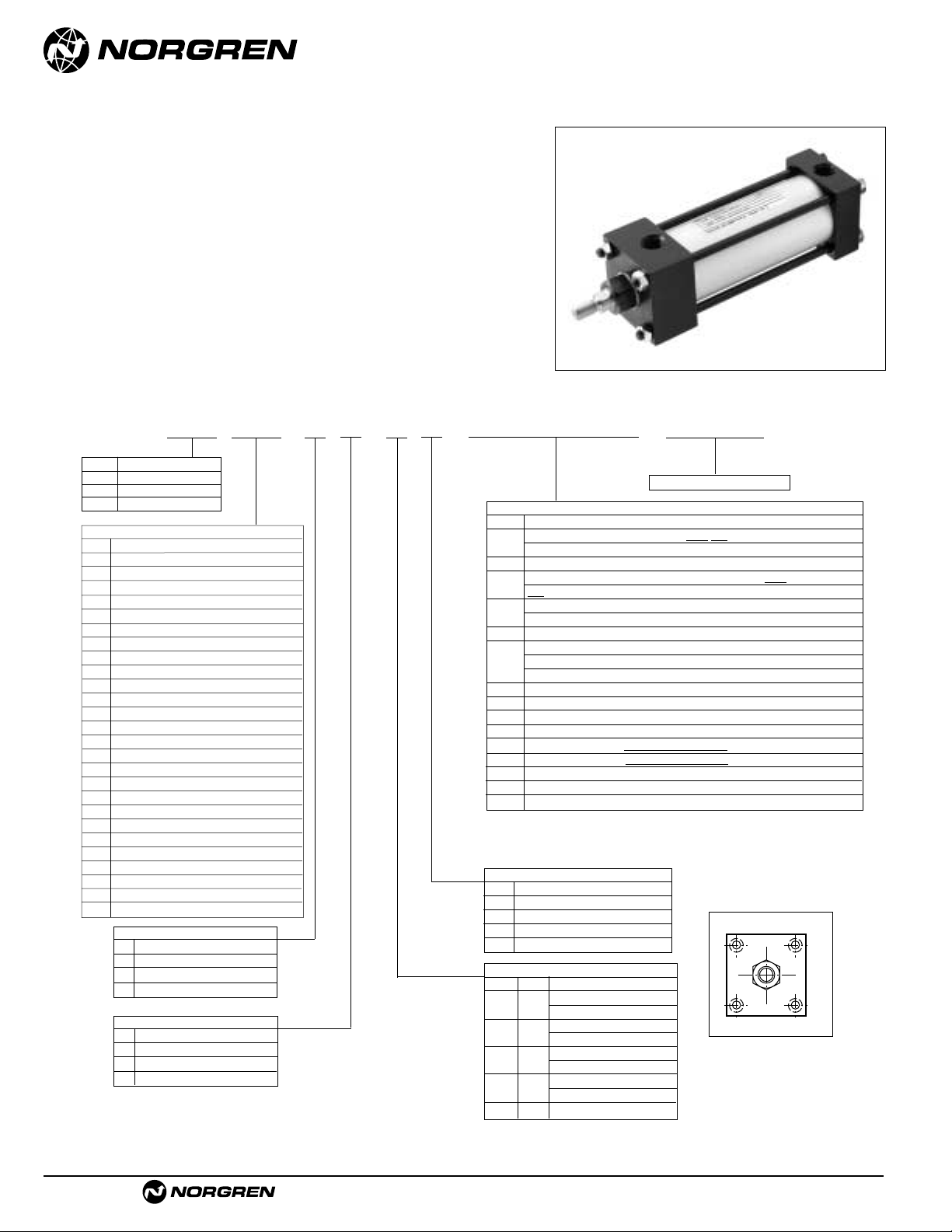
ACT-1-30
Brookville, OH USA Phone 937-833-4033 www.norgren.com
Series A & EA, NFPA Aluminum Air Cylinders (ø1-1/2 to 8")
Series J & EJ, NFPA Steel Air Cylinders (ø1-1/2 to 12")
● NFPA (MX0) 05 Basic Mount,
for 7" to 12" bore sizes.
● Series A & J Cylinders rated to 250 PSI air,
400 PSI hydraulic (non-shock).
Series EA & EJ Cylinders rated to 250 PSI air only.
● Designed for non-lube service.
● Switches available on all bore sizes.
(See pages ACT-1-90 & 91 for ordering information.)
Cylinder with 05 (MX0) Basic
See page ACT-1-96 for complete
instructions on how to order cylinders.
Cylinder Order Information
*11/2", 2", 21/2" bore cylinders have 3/8" NPT Standard, 1/2" NPT oversize.
3
1
/4", 4", 5" bore cylinders have 1/2" NPT Standard, 3/4" NPT oversize.
This will add
1
/8" to the overall cylinder length.
05
–
–
–
–
Bore and Stroke (write out )
Piston Rod Diameters
A**
5
/8" Standard on 11/2", 2", 21/2"
Standard on 3
1
/4", 4", 5"
B** 1"
Oversized on 1
1
/2", 2", 21/2"
Standard on 6", 7", 8"
C** 1
3
/
8"
Oversized on 3
1
/4", 4", 5"
Standard on 10"
D** 1
3
/
4"
Oversized on 6", 7", 8"
Standard on 12"
E2"
Oversized on 10"
F2
1
/2" Oversized on 10", 12"
Piston Rod Threads Type
1 Small Male (Solid)
2 Intermediate Thread Male (Solid)
3 Female
6 Full Thread Male (Solid)
7 Plain Rod End
Port and Cushion Adjustment
Positions
(As viewed from rod end:
Port standard position 1, Cushion
Adjustment standard position 2.)
NOTE: A Port and a Cushion Adjustment
cannot be in the same position.
A Series A Cylinder
EA Series EA Cylinder
J Series J Cylinder
EJ Series EJ Cylinder
** A & EA uses A-D only.
Additional Options – order alphabetically – More on page ACT-1-95
HR Case Hardened (45 Rc)
L(
_ _
) Port Location position 1 standard: L(Head Cap)
(specify position 1 thru 4 for head and/or cap)
MS Metal Rod Scraper
N(
_ _
) Cushion Adjust Screw Location position 2 standard: N(Head
Cap) (specify position 1 thru 4 for head and/or cap)
P(_)* Non-Standard Port Sizes: [specify port size for P(_H) head
only, P(_C) cap only, or P(_) both head & cap]
PS Magnetic Piston – includes aluminum tube option for J & EJ - Std. for Alum
RS Rod Stud
Type 1 (5/8" – 1
3
/4" øRod)
Type 2 (5/8" & 1" øRod)
RX Rod Extensions (specify length of additional rod extension)
SC Single Acting Spring Extend (Cap End)–See page ACT-1-86
SR Single Acting Spring Retract (Rod End)–See page ACT-1-86
SS 303 Stainless Steel (Hard Chrome Plated)
ST(_C) Stop Tube (Cap End) (specify stop tube length
)
ST(_R) Stop Tube (Rod End) (specify stop tube length
)
T Special Rod Threads (specify rod thread)
TX Thread Extensions (specify length of thread extension)
V Viton
®
Seals
Mounting Options
01 Side Tapped (MS4)
03 Head Rectangular Flange (MF1)
03 Head Square (ME3)–7" to 12" Bores
04 Cap Rectangular Flange (MF2)
04 Cap Square (ME4)–7" to 12" Bores
05 Basic Cylinder No Mounting (MX0)
06 Both Ends (4) Tie Rods Ext. (MX1)
6B Both Ends (2) Tie Rods Ext. (MX4)
6C Cap Tie Rods Ext. (MX2)
6R Head Tie Rods Ext. (MX3)
7R Removable Head Trunion (MT1) - A & EA
07 Head Trunnion (MT1) - J & EJ
8R Cap Trunion (MT2) - A & EA
08 Cap Trunnion (MT2( - J & EJ
09 Side Lugs (MS2)
10 Center Trunnion (MT4)
11 Side End Angles (MS1)
12 Cap Fixed Clevis (MP1)
15 Side End Lugs (MS7)
16 Sleeve Nut Construction (Universal)
20 Head Square Flange (MF5)
21 Cap Square Flange (MF6)
22 Detachable Cap Clevis (MP2)
32 Cap Fixed Eye (MP3)
42 Detachable Cap Eye (MP4)
52 Spherical Bearing
60 Base Bar (Not NFPA - A & EA Only)
†
Standard with EA & EJ
†
Standard with EA & EJ
Cushion in Head
3 None
5
†
Non-Adjustable Cushion
7 Adjustable Cushion (Position 2)
9 Decel Cushion
Cushion in Cap
3 None
5
†
Non-Adjustable Cushion
7 Adjustable Cushion (Position 2)
9 Decel Cushion
42
1
3
Page 31

Brookville, OH USA Phone 937-833-4033 www.norgren.com
ACT-1-31
Series A & EA, NFPA Aluminum Air Cylinders with 05 (MX0) Basic
Series J & EJ, NFPA Steel Air Cylinders with 05 (MX0) Basic
All Dimensions in Inches (mm)
1.3/
8"1.
3
/
8"1.
3
/
4" .2"
1.
3
/4"1.3/4" .2" 2.1/2"
1.625 1.625 2.000 2.250
2.000 2.000 2.250 3.000
1.999 1.999 2.374 2.624
2.374 2.374 2.624 3.124
.625 .625 .750 .875
.750 .750 .875 1.000
1.125 1.125 1.500 1.688
1.500 1.500 1.688 2.063
7.500 8.500 10.625 12.750
.750 .750 1.000 1.000
2.000 2.000 2.250 2.250
1.500 1.500 2.000 2.000
.563 .563 .688 .688
5.125 5.125 6.375 6.875
1.375 1.375 1.750 2.000
1.750 1.750 2.000 2.500
3.250 3.250 4.125 4.625
5.730 6.442 7.969 9.406
1.000 1.000 1.125 1.125
1.125 1.125 1.125 1.250
1.625 1.625 1.875 2.000
1.875 1.875 2.000 2.250
2.813 2.813 3.125 3.250
3.063 3.063 3.250 3.500
7.313 7.313 8.938 9.563
7.563 7.563 9.063 9.813
(34.93) (34.93) (44.45) (50.80)
(44.45) (44.45) (50.80) (63.50)
(41.28) (41.28) (50.80) (57.15)
(50.80) (50.80) (57.15) (76.20)
(50.78) (50.78) (60.30) (66.65)
(60.30) (60.30) (66.65) (79.35)
(15.88) (15.88) (19.05) (22.23)
(19.05) (19.05) (22.23) (25.40)
(28.58) (28.58) (38.10) (42.86)
(38.10) (38.10) (42.86) (52.39)
(190.50) (215.90) (269.88) (323.85)
(19.05) (19.05) (25.40) (25.40)
(50.80) (50.80) (57.15) (57.15)
(38.10) (38.10) (50.80) (50.80)
(14.29) (14.29) (17.46) (17.46)
(130.18) (130.18) (161.93) (174.63)
(34.93) (34.93) (44.45) (50.80)
(44.45) (44.45) (50.80) (63.50)
(82.55) (82.55) (104.78) (117.48)
(145.54) (163.63) (202.41) (238.92)
(25.40) (25.40) (28.58) (28.58)
(28.58) (28.58) (28.58) (31.75)
(41.28) (41.28) (47.63) (50.80)
(47.63) (47.63) (50.80) (57.15)
(71.44) (71.44) (79.38) (82.55)
(77.79) (77.79) (82.55) (88.90)
(185.74) (185.74) (227.01) (242.89)
(192.09) (192.09) (230.19) (249.24)
A
C
VF
G
ZB + Stroke
LB + Stroke
J
K
P + StrokeY
øB Bushing
øMM
KK
Thds
D
(Flats)
EE NPT (2)
R
E Sq.
WF
Standard & Optional Rod Ends
Dimension 7" Bore (177.80) 8" Bore (203.20) 10" Bore (254.00) 12" Bore (304.80) 14" Bore ()
ø Rod
Std.
O.S.
A
Std.
O.S.
B
+.000 Std.
-.002 O.S.
C
Std.
O.S.
CC
Std. 1
1
/4 – 12 11/4 – 12 11/2 – 12 13/4 – 12
O.S. 1
1
/2 – 12 11/2 – 12 13/4 – 12 21/4 – 12
D
Std.
O.S.
E
EE
FF
Std. 1
3
/8 – 12 13/8 – 12 13/4 – 12 2 – 12
O.S. 1
3
/4 – 12 13/4 – 12 2 – 12 21/2 – 12
G
J
K
KK
Std. 1 – 14 1 – 14 1
1
/4 – 12 11/2 – 12
O.S. 1
1
/4 – 12 11/4 – 12 11/2 – 12 17/8 – 12
LB
MM
Std.
O.S.
P
R
VF
Std.
O.S.
WF
Std.
O.S.
Y
Std.
O.S.
ZB
Std.
O.S.
D
Across
Flats
ø B
KK
Thds.
øMM
A
C
VF
Type 1 Solid
(Small Male)
ø B
KK
Thds.
øMM
A
C
VF
Type 1 Studded
(Studded Male Optional)
ø B
CC
Thds.
A
C
VF
Type 2 Studded
(Intermediate Thread
Male Optional)
øMM
ø B
CC
Thds.
A
C
Type 2 Solid
(Intermediate Thread
Male Optional)
ø B
KK
Thds.
A Deep
øMM
VF
Type 3 Female
C
VF
(Optional)
øMM
FF
Thds.
ø B
A
Type 6 Solid
(Full Thread
Male Optional)
øMM
C
VF
Page 32

ACT-1-32
Brookville, OH USA Phone 937-833-4033 www.norgren.com
Series A & EA, NFPA Aluminum Air Cylinders (ø1-1/2 to 8")
Series J & EJ, NFPA Steel Air Cylinders (ø1-1/2 to 12")
● NFPA (MX1) 06 (4) Extended Tie Rods Both Ends Mount
NFPA (MX2) 6C Cap Tie Rods Extended Mount
NFPA (MX3) 6R Head Tie Rods Extended Mount
NFPA (MX4) 6B (2) Extended Tie Rods Both Ends Mount
for 1-1/2" to 6" bore sizes.
● Series A & J Cylinders rated to 250 PSI air,
400 PSI hydraulic (non-shock).
Series EA & EJ Cylinders rated to 250 PSI air only.
● Designed for non-lube service.
● Switches available on all bore sizes.
(See pages ACT-1-90 & 91 for ordering information.)
Cylinder with 06 (MX1) Both Ends (4)
Tie Rods Extended Shown
See page ACT-1-96 for complete
instructions on how to order cylinders.
*11/2", 2", 21/2" bore cylinders have 3/8" NPT Standard, 1/2" NPT oversize.
3
1
/4", 4", 5" bore cylinders have 1/2" NPT Standard, 3/4" NPT oversize.
This will add
1
/8" to the overall cylinder length.
Cylinder Order Information
06
6B
6C
6R
–
–
–
–
Bore and Stroke (write out )
Piston Rod Diameters
A**
5
/8" Standard on 11/2", 2", 21/2"
Standard on 3
1
/4", 4", 5"
B** 1"
Oversized on 1
1
/2", 2", 21/2"
Standard on 6", 7", 8"
C** 1
3
/8"
Oversized on 3
1
/4", 4", 5"
Standard on 10"
D** 1
3
/4"
Oversized on 6", 7", 8"
Standard on 12"
E2"
Oversized on 10"
F2
1
/2" Oversized on 10", 12"
1
3
42
Piston Rod Threads Type
1 Small Male (Solid)
2 Intermediate Thread Male (Solid)
3 Female
6 Full Thread Male (Solid)
7 Plain Rod End
Port and Cushion Adjustment
Positions (As viewed from rod end:
Port standard position 1, Cushion
Adjustment standard position 2.)
NOTE: A Port and a Cushion Adjustment
cannot be in the same position.
A Series A Cylinder
EA Series EA Cylinder
J Series J Cylinder
EJ Series EJ Cylinder
** A & EA uses A-D only.
Additional Options – order alphabetically – More on page ACT-1-95
HR Case Hardened (45 Rc)
L(
_ _
) Port Location position 1 standard: L(Head
Cap)
(specify position 1 thru 4 for head and/or cap)
MS Metal Rod Scraper
N(
_ _
) Cushion Adjust Screw Location position 2 standard: N(Head
Cap) (specify position 1 thru 4 for head and/or cap)
P(_)* Non-Standard Port Sizes: [specify port size for P(_H) head
only, P(_C) cap only, or P(_) both head & cap]
PS Magnetic Piston – includes aluminum tube option for J & EJ - Std. for Alum
RS Rod Stud
Type 1 (5/8" – 1
3
/4" øRod)
Type 2 (5/8" & 1" øRod)
RX Rod Extensions (specify length of additional rod extension)
SC Single Acting Spring Extend (Cap End)–See page ACT-1-86
SR Single Acting Spring Retract (Rod End)–See page ACT-1-86
SS 303 Stainless Steel (Hard Chrome Plated)
ST(_C) Stop Tube (Cap End) (specify stop tube length
)
ST(_R) Stop Tube (Rod End) (specify stop tube length
)
T Special Rod Threads (specify rod thread)
TX Thread Extensions (specify length of thread extension)
V Viton
®
Seals
Mounting Options
01 Side Tapped (MS4)
03 Head Rectangular Flange (MF1)
03 Head Square (ME3)–7" to 12" Bores
04 Cap Rectangular Flange (MF2)
04 Cap Square (ME4)–7" to 12" Bores
05 Basic Cylinder No Mounting (MX0)
06 Both Ends (4) Tie Rods Ext. (MX1)
6B Both Ends (2) Tie Rods Ext. (MX4)
6C Cap Tie Rods Ext. (MX2)
6R Head Tie Rods Ext. (MX3)
7R Removable Head Trunion (MT1) - A & EA
07 Head Trunnion (MT1) - J & EJ
8R Cap Trunion (MT2) - A & EA
08 Cap Trunnion (MT2( - J & EJ
09 Side Lugs (MS2)
10 Center Trunnion (MT4)
11 Side End Angles (MS1)
12 Cap Fixed Clevis (MP1)
15 Side End Lugs (MS7)
16 Sleeve Nut Construction (Universal)
20 Head Square Flange (MF5)
21 Cap Square Flange (MF6)
22 Detachable Cap Clevis (MP2)
32 Cap Fixed Eye (MP3)
42 Detachable Cap Eye (MP4)
52 Spherical Bearing
60 Base Bar (Not NFPA - A & EA Only)
†
Standard with EA & EJ
†
Standard with EA & EJ
Cushion in Head
3 None
5
†
Non-Adjustable Cushion
7 Adjustable Cushion (Position 2)
9 Decel Cushion
Cushion in Cap
3 None
5
†
Non-Adjustable Cushion
7 Adjustable Cushion (Position 2)
9 Decel Cushion
Page 33

Brookville, OH USA Phone 937-833-4033 www.norgren.com
ACT-1-33
Series A & EA, NFPA Aluminum Air Cylinders Combinations with Extended Tie Rods
Series J & EJ, NFPA Steel Air Cylinders Combinations with Extended Tie Rods
All Dimensions in Inches (mm)
Standard & Optional Rod Ends
EE NPT (2)
Dimension 1
1
/
2
" Bore (38.10) 2" Bore (50.80) 2
1
/
2
" Bore (63.50) 3
1
/
4
" Bore (82.55) 4" Bore (101.60) 5" Bore (127.00) 6" Bore (152.40) 7" Bore (177.80) 8" Bore (203
ø Rod
Std.
O.S.
A
Std.
O.S.
AA
B
+.000 Std.
-.002 O.S.
BB
C
Std.
O.S.
CC
Std. 1/2 – 20 1/2 – 20 1/2 – 20 7/8 – 14 7/8 – 14 7/8 – 14 1
1
/4 – 12 11/4 – 12 11/4 – 12
O.S. 7/8 – 14 7/8 –14 7/8 – 14 1
1
/4 – 12 11/4 – 12 11/4 – 12 11/2 – 12 11/2 – 12 11/2 – 12
D
Std.
O.S.
DD 1/4 – 28 5/16 – 24 5/16 – 24 3/8 – 24 3/8 – 24 1/2 – 20 1/2 – 20 5/8 – 18 5/8 – 18
E
EE
F
FF
Std. 5/8 – 18 5/8 – 18 5/8 – 18 1 – 14 1 – 14 1 – 14 1
3
/8 – 12 13/8 – 12 13/8 – 12
O.S. 1 – 14 1 – 14 1 – 14 1
3
/8 – 12 13/8 – 12 13/8 – 12 13/4 – 12 13/4 – 12 13/4 – 12
G
J
K
KK
Std. 7/16 – 20 7/16 – 20 7/16 – 20 3/4 – 16 3/4 – 16 3/4 – 16 1 – 14 1 – 14 1 – 14
O.S. 3/4 – 16 3/4 – 16 3/4 – 16 1 – 14 1 – 14 1 – 14 1
1
/4 – 12 11/4 – 12 11/4 – 12
LB
MM
Std.
O.S.
P
R
VF
Std.
O.S.
WF
Std.
O.S.
Y
Std.
O.S.
ZB
Std.
O.S.
(15.88) (15.88) (15.88) (25.40) (25.40) (25.40) (34.93) (34.93) (34
(25.40) (25.40) (25.40) (34.93) (34.93) (34.93) (44.45) (44.45) (44
(19.05) (19.05) (19.05) (28.58) (28.58) (28.58) (41.28) (41.28) (41
(28.58) (28.58) (28.58) (41.28) (41.28) (41.28) (50.80) (50.80) (50
(51.31) (66.04) (78.74) (99.06) (119.38) (147.32) (175.26) (205.74) (231
(28.55) (28.55) (28.55) (38.08) (38.08) (38.08) (50.78) (50.78) (50
(38.08) (38.08) (38.08) (50.78) (50.78) (50.78) (60.30) (60.30) (60
(25.40) (28.58) (28.58) (34.93) (34.93) (46.04) (46.04) (58.74) (58
(9.53) (9.53) (9.53) (12.70) (12.70) (12.70) (15.88) (15.88) (15
(12.70) (12.70) (12.70) (15.88) (15.88) (15.88) (19.05) (19.05 (19
(12.70) (12.70) (12.70) (20.64) (20.64) (20.64) (28.58) (28.58) (28
(20.64) (20.64) (20.64) (28.58) (28.58) (28.58) (38.10) (38.10) (38
(50.80) (63.50) (76.20) (95.25) (114.30) (139.70) (165.10) (190.50) (215
(9.53) (9.53) (9.53) (12.70) (12.70) (12.70) (19.05) (19.05) (19
(9.53) (9.53) (9.53) (15.88) (15.88) (15.88) (19.05) (19.05) (19
(38.10) (38.10) (38.10) (44.45) (44.45) (44.45) (50.80) (50.80) (50
(25.40) (25.40) (25.40) (31.75) (31.75) (31.75) (38.10) (38.10) (38
(6.35) (7.94) (7.94) (9.53) (9.53) (11.11) (11.11) (14.29) (14
(92.08) (92.08) (95.25) (107.95) (107.95) (114.30) (127.00) (130.18) (130
(15.88) (15.88) (15.88) (25.40) (25.40) (25.40) (34.93) (34.93) (34
(25.40) (25.40) (25.40) (34.93) (34.93) (34.93) (44.45) (44.45) (44
(59.44) (59.44) (62.74) (68.33) (68.33) (74.68) (79.38) (82.55) (82
(36.27) (46.68) (55.67) (70.05) (84.40) (104.16) (123.92) (145.54) (163
(15.88) (15.88) (15.88) (22.23) (22.23) (22.23) (25.40) (25.40) (25
(22.23) (22.23) (22.23) (25.40) (25.40) (25.40) (28.58) (28.58) (28
(25.40) (25.40) (25.40) (34.93) (34.93) (34.93) (41.28) (41.28) (41
(34.93) (34.93) (34.93) (41.28) (41.28) (41.28) (47.63) (47.63) (47
(46.74) (46.74) (46.74) (60.45) (60.45) (60.45) (71.44) (71.44) (71
(56.39) (56.39) (56.39) (66.80) (66.80) (66.80) (77.79) (77.79) (77
(123.83) (125.41) (128.59) (152.40) (152.40) (160.34) (179.39) (185.74) (185
(133.35) (134.94) (138.11) (158.75) (158.75) (166.69) (185.74) (192.10) (192
.5/8" .5/8" .5/8" .1" .1" .1" 1.
3
/8"1.3/8"1.3/8"
.1" .1" .1" 1.
3
/8"1.3/8"1.3/8"1.3/4"1.3/4"1.3/4"
.750 .750 .750 1.125 1.125 1.125 1.625 1.625 1.625
1.125 1.125 1.125 1.625 1.625 1.625 2.000 2.000 2.000
2.020 2.600 3.100 3.900 4.700 5.800 6.900 8.100 9.100
1.124 1.124 1.124 1.499 1.499 1.499 1.999 1.999 1.999
1.499 1.499 1.499 1.999 1.999 1.999 2.374 2.374 2.374
1.000 1.125 1.125 1.375 1.375 1.813 1.813 2.313 2.313
.375 .375 .375 .500 .500 .500 .625 .625 .625
.500 .500 .500 .625 .625 .625 .750 .625 .750
.500 .500 .500 .813 .813 .813 1.125 1.125 1.125
.813 .813 .813 1.125 1.125 1.125 1.500 1.500 1.500
2.000 2.500 3.000 3.750 4.500 5.500 6.500 7.500 8.500
.375 .375 .375 .500 .500 .500 .750 .750 .750
.375 .375 .375 .625 .625 .625 .750 .750 .750
1.500 1.500 1.500 1.750 1.750 1.750 2.000 2.000 2.000
1.000 1.000 1.000 1.250 1.250 1.250 1.500 1.500 1.500
.250 .313 .313 .375 .375 .438 .438 .563 .563
3.625 3.625 3.750 4.250 4.250 4.500 5.000 5.125 5.125
.625 .625 .625 1.000 1.000 1.000 1.375 1.375 1.375
1.000 1.000 1.000 1.375 1.375 1.375 1.750 1.750 1.750
2.340 2.340 2.470 2.690 2.690 2.940 3.125 3.250 3.250
1.428 1.838 2.192 2.758 3.323 4.101 4.879 5.730 6.442
.625 .625 .625 .875 .875 .875 1.000 1.000 1.000
.875 .875 .875 1.000 1.000 1.000 1.125 1.125 1.125
1.000 1.000 1.000 1.375 1.375 1.375 1.625 1.625 1.625
1.375 1.375 1.375 1.625 1.625 1.625 1.875 1.875 1.875
1.840 1.840 1.840 2.380 2.380 2.380 2.813 2.813 2.813
2.220 2.220 2.220 2.630 2.630 2.630 3.063 3.063 3.063
4.875 4.938 5.063 6.000 6.000 6.313 7.063 7.313 7.313
5.250 5.313 5.438 6.250 6.250 6.563 7.313 7.563 7.563
06 (MX1)
øB Bushing
øMM
KK
Thds
WF
F
P + StrokeY
DD
Thds
AA
D
(Flats)
R
E Sq.
6C (MX2)
ZB + Stroke
BB
ø B
KK
Thds.
A
C
Type 1 Studded
(Studded Male Optional)
D
Across
Flats
ø B
KK
Thds.
øMM
A
C
VF
Type 1 Solid
(Small Male)
A
C
BB BB
6R (MX3)
DD
Thds.
CC
Thds.
øMM
VF
G
VF
BB
DD
Thds.
ø B
A
C
VF
Type 2 Studded
(Intermediate Thread
Male Optional)
LB + Stroke
ZB + Stroke
ZB + Stroke
ø B
CC
Thds.
øMM
A
Type 2 Solid
(Intermediate Thread
J
øMM
C
VF
Male Optional)
K
6B (MX4)
DD
Thds.
ø B
KK
Thds.
A Deep
ZB + Stroke
øMM
C
VF
Type 3 Female
(Optional)
R
BB
ø B
FF
Thds.
øMM
A
C
VF
Type 6 Solid
(Full Thread
Male Optional)
Page 34

ACT-1-34
Brookville, OH USA Phone 937-833-4033 www.norgren.com
Series A & EA, NFPA Aluminum Air Cylinders (ø1-1/2 to 8")
Series J & EJ, NFPA Steel Air Cylinders (ø1-1/2 to 12")
● NFPA (MX1) 06 (4) Extended Tie Rods Both Ends Mount
NFPA (MX2) 6C Cap Tie Rods Extended Mount
NFPA (MX3) 6R Head Tie Rods Extended Mount
NFPA (MX4) 6B (2) Extended Tie Rods Both Ends Mount
for 7" to 12" bore sizes.
● Series A & J Cylinders rated to 250 PSI air,
400 PSI hydraulic (non-shock).
Series EA & EJ Cylinders rated to 250 PSI air only.
● Designed for non-lube service.
● Switches available on all bore sizes.
(See pages ACT-1-90 & 91 for ordering information.)
Cylinder with 06 (MX1) Both Ends (4)
Tie Rods Extended Shown
See page ACT-1-96 for complete
instructions on how to order cylinders.
*11/2", 2", 21/2" bore cylinders have 3/8" NPT Standard, 1/2" NPT oversize.
3
1
/4", 4", 5" bore cylinders have 1/2" NPT Standard, 3/4" NPT oversize.
This will add
1
/8" to the overall cylinder length.
Cylinder Order Information
06
6B
6C
6R
–
–
–
–
Bore and Stroke (write out )
Piston Rod Diameters
A**
5
/8" Standard on 11/2", 2", 21/2"
Standard on 3
1
/4", 4", 5"
B** 1"
Oversized on 1
1
/2", 2", 21/2"
Standard on 6", 7", 8"
C** 1
3
/8"
Oversized on 3
1
/4", 4", 5"
Standard on 10"
D** 1
3
/4"
Oversized on 6", 7", 8"
Standard on 12"
E2"
Oversized on 10"
F2
1
/2" Oversized on 10", 12"
Piston Rod Threads Type
1 Small Male (Solid)
2 Intermediate Thread Male (Solid)
3 Female
6 Full Thread Male (Solid)
7 Plain Rod End
Port and Cushion Adjustment
Positions (As viewed from rod end:
Port standard position 1, Cushion
Adjustment standard position 2.)
NOTE: A Port and a Cushion Adjustment
cannot be in the same position.
A Series A Cylinder
EA Series EA Cylinder
J Series J Cylinder
EJ Series EJ Cylinder
** A & EA uses A-D only.
Additional Options – order alphabetically – More on page ACT-1-95
HR Case Hardened (45 Rc)
L(
_ _
) Port Location position 1 standard: L(Head
Cap)
(specify position 1 thru 4 for head and/or cap)
MS Metal Rod Scraper
N(
_ _
) Cushion Adjust Screw Location position 2 standard: N(Head
Cap) (specify position 1 thru 4 for head and/or cap)
P(_)* Non-Standard Port Sizes: [specify port size for P(_H) head
only, P(_C) cap only, or P(_) both head & cap]
PS Magnetic Piston – includes aluminum tube option for J & EJ - Std. for Alum
RS Rod Stud
Type 1 (5/8" – 1
3
/4" øRod)
Type 2 (5/8" & 1" øRod)
RX Rod Extensions (specify length of additional rod extension)
SC Single Acting Spring Extend (Cap End)–See page ACT-1-86
SR Single Acting Spring Retract (Rod End)–See page ACT-1-86
SS 303 Stainless Steel (Hard Chrome Plated)
ST(_C) Stop Tube (Cap End) (specify stop tube length
)
ST(_R) Stop Tube (Rod End) (specify stop tube length
)
T Special Rod Threads (specify rod thread)
TX Thread Extensions (specify length of thread extension)
V Viton
®
Seals
Mounting Options
01 Side Tapped (MS4)
03 Head Rectangular Flange (MF1)
03 Head Square (ME3)–7" to 12" Bores
04 Cap Rectangular Flange (MF2)
04 Cap Square (ME4)–7" to 12" Bores
05 Basic Cylinder No Mounting (MX0)
06 Both Ends (4) Tie Rods Ext. (MX1)
6B Both Ends (2) Tie Rods Ext. (MX4)
6C Cap Tie Rods Ext. (MX2)
6R Head Tie Rods Ext. (MX3)
7R Removable Head Trunion (MT1) - A & EA
07 Head Trunnion (MT1) - J & EJ
8R Cap Trunion (MT2) - A & EA
08 Cap Trunnion (MT2( - J & EJ
09 Side Lugs (MS2)
10 Center Trunnion (MT4)
11 Side End Angles (MS1)
12 Cap Fixed Clevis (MP1)
15 Side End Lugs (MS7)
16 Sleeve Nut Construction (Universal)
20 Head Square Flange (MF5)
21 Cap Square Flange (MF6)
22 Detachable Cap Clevis (MP2)
32 Cap Fixed Eye (MP3)
42 Detachable Cap Eye (MP4)
52 Spherical Bearing
60 Base Bar (Not NFPA - A & EA Only)
†
Standard with EA & EJ
†
Standard with EA & EJ
Cushion in Head
3 None
5
†
Non-Adjustable Cushion
7 Adjustable Cushion (Position 2)
9 Decel Cushion
Cushion in Cap
3 None
5
†
Non-Adjustable Cushion
7 Adjustable Cushion (Position 2)
9 Decel Cushion
1
42
3
Page 35

Brookville, OH USA Phone 937-833-4033 www.norgren.com
ACT-1-35
Series A & EA, NFPA Aluminum Air Cylinder Combinations with Extended Tie Rods
Series J & EJ, NFPA Steel Air Cylinder Combinations with Extended Tie Rods
All Dimensions in Inches (mm)
1.3/
8"1.
3
/
8"1.
3
/
4"2"
1.
3
/
4"1.
3
/
4"2" 2.
1
/
2"
1.625 1.625 2.000 2.250
2.000 2.000 2.250 3.000
8.100 9.100 11.313 13.313
1.999 1.999 2.374 2.624
2.374 2.374 2.624 3.124
2.313 2.313 2.688 2.688
.625 .625 .750 .875
.625 .750 .875 1.000
1.125 1.125 1.500 1.688
1.500 1.500 1.688 2.063
7.500 8.500 10.625 12.750
.750 .750 1.000 1.000
.750 .750
2.000 2.000 2.250 2.250
1.500 1.500 2.000 2.000
.563 .563 .688 .688
5.125 5.125 6.375 6.875
1.375 1.375 1.750 2.000
1.750 1.750 2.000 2.500
3.250 3.250 4.125 4.625
5.730 6.442 7.969 9.406
1.000 1.000 1.125 1.125
1.125 1.125 1.125 1.250
1.625 1.625 1.875 2.000
1.875 1.875 2.000 2.250
2.813 2.813 3.125 3.250
3.063 3.063 3.250 3.500
7.313 7.313 8.938 9.563
7.563 7.563 9.063 9.813
(34.93) (34.93) (44.45) (50.80)
(44.45) (44.45) (50.80) (63.50)
(41.28) (41.28) (50.80) (57.15)
(50.80) (50.80) (57.15) (76.20)
(205.74) (231.14) (287.34) (338.14)
(50.78) (50.78) (60.30) (66.65)
(60.30) (60.30) (66.65) (79.35)
(58.74) (58.74) (68.26) (68.26)
(15.88) (15.88) (19.05) (22.23)
(19.05 (19.05) (22.23) (25.40)
(28.58) (28.58) (38.10) (42.86)
(38.10) (38.10) (42.86) (52.39)
(190.50) (215.90) (269.88) (323.85)
(19.05) (19.05) (25.40) (25.40)
(19.05) (19.05)
(50.80) (50.80) (57.15) (57.15)
(38.10) (38.10) (50.80) (50.80)
(14.29) (14.29) (17.46) (17.46)
(130.18) (130.18) (161.93) (174.63)
(34.93) (34.93) (44.45) (50.80)
(44.45) (44.45 ) (50.80) (63.50)
(82.55) (82.55) (104.78) (117.48)
(145.54) (163.63) (202.41) (238.92)
(25.40) (25.40) (28.58) (28.58)
(28.58) (28.58) (28.58) (31.75)
(41.28) (41.28) (47.63) (50.80)
(47.63) (47.63) (50.80) (57.15)
(71.44) (71.44) (79.38) (82.55)
(77.79) (77.79) (82.55) (88.90)
(185.74) (185.74) (227.01) (242.89)
(192.09) (192.09) (230.19) (249.24)
Dimension 7" Bore (177.80) 8" Bore (203.20) 10" Bore (254.00) 12" Bore (304.80)
ø Rod
Std.
O.S.
A
Std.
O.S.
AA
B
+.000 Std.
-.002 O.S.
BB
C
Std.
O.S.
CC
Std. 1
1
/4 – 12 11/4 – 12 11/2 – 12 13/4 – 12
O.S. 1
1
/2 – 12 11/2 – 12 13/4 – 12 21/4 – 12
D
Std.
O.S.
DD 5/8 – 18 5/8 – 18 3/4 – 16 3/4 – 16
E
EE
F ——
FF
Std. 1
3
/8 – 12 13/8 – 12 13/4 – 12 2 – 12
O.S. 1
3
/4 – 12 13/4 – 12 2 – 12 21/2 – 12
G
J
K
KK
Std. 1 – 14 1 – 14 1
1
/4 – 12 11/2 – 12
O.S. 1
1
/4 – 12 11/4 – 12 11/2 – 12 17/8 – 12
LB
MM
Std.
O.S.
P
R
VF
Std.
O.S.
WF
Std.
O.S.
Y
Std.
O.S.
ZB
Std.
O.S.
Standard & Optional Rod Ends
EE NPT (2)
DD
Thds
06 (MX1)
øB Bushing
øMM
KK
Thds
P + StrokeY
WF
F
AA
D
(Flats)
R
E Sq.
6C (MX2)
ZB + Stroke
BB
ø B
KK
Thds.
A
C
Type 1 Studded
(Studded Male Optional)
D
Across
Flats
ø B
KK
Thds.
øMM
A
C
VF
Type 1 Solid
(Small Male)
A
C
BB BB
6R (MX3)
DD
Thds.
CC
Thds.
øMM
VF
G
VF
DD
Thds.
ø B
BB
LB + Stroke
ZB + Stroke
ZB + Stroke
ø B
CC
Thds.
øMM
A
C
VF
Type 2 Studded
(Intermediate Thread
Male Optional)
A
C
Type 2 Solid
(Intermediate Thread
Male Optional)
J
øMM
VF
K
6B (MX4)
DD
Thds.
ø B
KK
Thds.
A Deep
Type 3 Female
C
VF
(Optional)
ZB + Stroke
øMM
FF
Thds.
R
BB
ø B
A
Type 6 Solid
(Full Thread
Male Optional)
øMM
C
VF
Page 36

ACT-1-36
Brookville, OH USA Phone 937-833-4033 www.norgren.com
Series A & EA, NFPA Aluminum Air Cylinders (ø1-1/2 to 8")
Series J & EJ, NFPA Steel Air Cylinders (ø1-1/2 to 12")
● NFPA (MT1) 07 Head Trunnion Mount
for 1-1/2" to 6" bore sizes.
● Series A & J Cylinders rated to 250 PSI air,
400 PSI hydraulic (non-shock).
Series EA & EJ Cylinders rated to 250 PSI air only.
● Designed for non-lube service.
● Switches available on all bore sizes.
(See page ACT-1-90 & 91 for ordering information.)
● Head Trunnions are removable.
Cylinder with 07 (MT1) Head Trunnion
See page ACT-1-96 for complete
instructions on how to order cylinders.
Cylinder Order Information
*11/2", 2", 21/2" bore cylinders have 3/8" NPT Standard, 1/2" NPT oversize.
3
1
/4", 4", 5" bore cylinders have 1/2" NPT Standard, 3/4" NPT oversize.
This will add
1
/8" to the overall cylinder length.
Mounting Options
01 Side Tapped (MS4)
03 Head Rectangular Flange (MF1)
03 Head Square (ME3)–7" to 12" Bores
04 Cap Rectangular Flange (MF2)
04 Cap Square (ME4)–7" to 12" Bores
05 Basic Cylinder No Mounting (MX0)
06 Both Ends (4) Tie Rods Ext. (MX1)
6B Both Ends (2) Tie Rods Ext. (MX4)
6C Cap Tie Rods Ext. (MX2)
6R Head Tie Rods Ext. (MX3)
7R Removable Head Trunion (MT1) - A & EA
07 Head Trunnion (MT1) - J & EJ
8R Cap Trunion (MT2) - A & EA
08 Cap Trunnion (MT2( - J & EJ
09 Side Lugs (MS2)
10 Center Trunnion (MT4)
11 Side End Angles (MS1)
12 Cap Fixed Clevis (MP1)
15 Side End Lugs (MS7)
16 Sleeve Nut Construction (Universal)
20 Head Square Flange (MF5)
21 Cap Square Flange (MF6)
22 Detachable Cap Clevis (MP2)
32 Cap Fixed Eye (MP3)
42 Detachable Cap Eye (MP4)
52 Spherical Bearing
60 Base Bar (Not NFPA - A & EA Only)
07
–
–
–
–
Bore and Stroke (write out )
Piston Rod Diameters
A**
5
/8" Standard on 11/2", 2", 21/2"
Standard on 3
1
/4", 4", 5"
B** 1"
Oversized on 1
1
/2", 2", 21/2"
Standard on 6", 7", 8"
C** 1
3
/8"
Oversized on 3
1
/4", 4", 5"
Standard on 10"
D** 1
3
/4"
Oversized on 6", 7", 8"
Standard on 12"
E2"
Oversized on 10"
F2
1
/2" Oversized on 10", 12"
Piston Rod Threads Type
1 Small Male (Solid)
2 Intermediate Thread Male (Solid)
3 Female
6 Full Thread Male (Solid)
7 Plain Rod End
7R
Port and Cushion Adjustment
Positions (As viewed from rod end:
Port standard position 1, Cushion
Adjustment standard position 2.)
NOTES: A Port and a Cushion Adjustment
cannot be in the same position.
Port or cushion cannot be located in
position 2 or 4 on the head end.
A Series A Cylinder
EA Series EA Cylinder
J Series J Cylinder
EJ Series EJ Cylinder
** A & EA uses A-D only.
Additional Options – order alphabetically – More on page ACT-1-95
HR Case Hardened (45 Rc)
L(
_ _
) Port Location position 1 standard: L(Head
Cap)
(specify position 1 thru 4 for head and/or cap)
MS Metal Rod Scraper
N(
_ _
) Cushion Adjust Screw Location position 2 standard: N(Head
Cap) (specify position 1 thru 4 for head and/or cap)
P(_)* Non-Standard Port Sizes: [specify port size for P(_H) head
only, P(_C) cap only, or P(_) both head & cap]
PS Magnetic Piston – includes aluminum tube option for J & EJ - Std. for Alum
RS Rod Stud
Type 1 (5/8" – 1
3
/4" øRod)
Type 2 (5/8" & 1" øRod)
RX Rod Extensions (specify length of additional rod extension)
SC Single Acting Spring Extend (Cap End)–See page ACT-1-86
SR Single Acting Spring Retract (Rod End)–See page ACT-1-86
SS 303 Stainless Steel (Hard Chrome Plated)
ST(_C) Stop Tube (Cap End) (specify stop tube length
)
ST(_R) Stop Tube (Rod End) (specify stop tube length
)
T Special Rod Threads (specify rod thread)
TX Thread Extensions (specify length of thread extension)
V Viton
®
Seals
†
Standard with EA & EJ
†
Standard with EA & EJ
Cushion in Head
3 None
5
†
Non-Adjustable Cushion
7 Adjustable Cushion (Position 2)
9 Decel Cushion
Cushion in Cap
3 None
5
†
Non-Adjustable Cushion
7 Adjustable Cushion (Position 2)
9 Decel Cushion
1
42
3
Page 37

Brookville, OH USA Phone 937-833-4033 www.norgren.com
ACT-1-37
Series A & EA, NFPA Aluminum Air Cylinders with 7R (MT1) Head Trunnion
Series J & EJ, NFPA Steel Air Cylinders with 07 (MT1) Head Trunnion
All Dimensions in Inches (mm)
Standard & Optional Rod Ends
øTD
.5/8" .5/8" .5/8" .1" .1" .1" 1.3/8
"1.
3
/8
"1.
3
/8
"
.1" .1" .1" 1.
3
/8"1.3/8"1.3/8"1.3/4"1.3/4"1.3/4"
.750 .750 .750 1.125 1.125 1.125 1.625 1.625 1.625
1.125 1.125 1.125 1.625 1.625 1.625 2.000 2.000 2.000
1.124 1.124 1.124 1.499 1.499 1.499 1.999 1.999 1.999
1.499 1.499 1.499 1.999 1.999 1.999 2.374 2.374 2.374
.375 .375 .375 .500 .500 .500 .625 .625 .625
.500 .500 .500 .625 .625 .625 .750 .750 .750
.500 .500 .500 .875 .875 .875 1.125 1.125 1.125
.875 .875 .875 1.125 1.125 1.125 1.500 1.500 1.500
2.000 2.500 3.000 3.750 4.500 5.500 6.500 7.500 8.500
.375 .375 .375 .500 .500 .500 .750 .750 .750
1.500 1.500 1.500 1.750 1.750 1.750 2.000 2.000 2.000
1.000 1.000 1.000 1.250 1.250 1.250 1.500 1.500 1.500
.250 .313 .313 .375 .375 .438 .438 .563 .563
3.625 3.625 3.750 4.250 4.250 4.500 5.000 5.125 5.125
.625 .625 .625 1.000 1.000 1.000 1.375 1.375 1.375
1.000 1.000 1.000 1.375 1.375 1.375 1.750 1.750 1.750
2.340 2.340 2.470 2.690 2.690 2.940 3.125 3.250 3.250
1.428 1.838 2.192 2.758 3.323 4.101 4.879 5.730 6.435
1.000 1.000 1.000 1.000 1.000 1.000 1.375 1.375 1.375
1.000 1.000 1.000 1.000 1.000 1.000 1.375 1.375 1.375
4.000 4.500 5.000 5.750 6.500 7.500 9.250 10.250 11.250
.625 .625 .625 .875 .875 .875 1.000 1.000 1.000
.875 .875 .875 1.000 1.000 1.000 1.125 1.125 1.125
1.000 1.000 1.000 1.375 1.375 1.375 1.625 1.625 1.625
1.375 1.375 1.375 1.625 1.625 1.625 1.875 1.875 1.875
1.750 1.750 1.750 2.250 2.250 2.250 2.625 2.625 2.625
2.125 2.125 2.125 2.500 2.500 2.500 2.875 2.875 2.875
1.840 1.840 1.840 2.380 2.380 2.380 2.813 2.813 2.813
2.220 2.220 2.220 2.630 2.630 2.630 3.063 3.063 3.063
4.875 4.938 5.063 6.000 6.000 6.313 7.063 7.313 7.313
5.250 5.313 5.438 6.250 6.250 6.563 7.313 7.563 7.563
Dimension 1
1
/
2
" Bore (38.10) 2" Bore (50.80) 2
1
/
2
" Bore (63.50) 3
1
/
4
" Bore (82.55) 4" Bore (101.60) 5" Bore (127.00) 6" Bore (152.40) 7" Bore (177.80) 8" Bore (20
ø Rod
Std.
O.S.
A
Std.
O.S.
B
+.000 Std.
-.002 O.S.
C
Std.
O.S.
CC
Std. 1/2 – 20 1/2 – 20 1/2 – 20 7/8 – 14 7/8 – 14 7/8 – 14 1
1
/4 – 12 11/4 – 12 11/4 – 1
O.S. 7/8 – 14 7/8 – 14 7/8 – 14 1
1
/4 – 12 11/4 – 12 11/4 – 12 11/2 – 12 11/2 – 12 11/2 – 1
D
Std.
O.S.
E
EE
FF
Std. 5/8 – 18 5/8 – 18 5/8 – 18 1 – 14 1 – 14 1 – 14 1
3
/8 – 12 13/8 – 12 13/8 – 1
O.S. 1 – 14 1 – 14 1 – 14 1
3
/8 – 12 13/8 – 12 13/8 – 12 13/4 – 12 13/4 – 12 13/4 – 1
G
J
K
KK
Std. 7/16 – 20 7/16 – 20 7/16 – 20 3/4 – 16 3/4 – 16 3/4 – 16 1 – 14 1 – 14 1 – 14
O.S. 3/4 – 16 3/4 – 16 3/4 – 16 1 – 14 1 – 14 1 – 14 1
1
/4 – 12 11/4 – 12 11/4 – 1
LB
MM
Std.
O.S.
P
R
TD
+.000 -.001
TL
UT
VF
Std.
O.S.
WF
Std.
O.S.
XG
Std.
O.S.
Y
Std.
O.S.
ZB
Std.
O.S.
(15.88) (15.88) (15.88) (25.40) (25.40) (25.40) (34.93) (34.93) (3
(25.40) (25.40) (25.40) (34.93) (34.93) (34.93) (44.45) (44.45) (4
(19.05) (19.05) (19.05) (28.58) (28.58) (28.58) (41.28) (41.28) (4
(28.58) (28.58) (28.58) (41.28) (41.28) (41.28) (50.80) (50.80) (5
(28.55) (28.55) (28.55) (38.08) (38.08) (38.08) (50.78) (50.78) (5
(38.08) (38.08) (38.08) (50.78) (50.78) (50.78) (60.30) (60.30) (6
(9.53) (9.53) (9.53) (12.70) (12.70) (12.70) (15.88) (15.88) (1
(12.70) (12.70) (12.70) (15.88) (15.88) (15.88) (19.05) (19.05) (1
(12.70) (12.70) (12.70) (22.23) (22.23) (22.23) (28.58) (28.58) (2
(22.23) (22.23) (22.23) (28.58) (28.58) (28.58) (38.10) (38.10) (3
(50.80) (63.50) (76.20) (95.25) (114.30) (139.70) (165.10) (190.50) (21
(9.53) (9.53) (9.53) (12.70) (12.70) (12.70) (19.05) (19.05) (1
(38.10) (38.10) (38.10) (44.45) (44.45) (44.45) (50.80) (50.80) (5
(25.40) (25.40) (25.40) (31.75) (31.75) (31.75) (38.10) (38.10) (3
(6.35) (7.94) (7.94) (9.53) (9.53) (11.11) (11.11) (14.29) (1
(92.08) (92.08) (95.25) (107.95) (107.95) (114.30) (127.00) (130.18) (13
(15.88) (15.88) (15.88) (25.40) (25.40) (25.40) (34.93) (34.93) (3
(25.40) (25.40) (25.40) (34.93) (34.93) (34.93) (44.45) (44.45) (4
(59.44) (59.44) (62.74) (68.33) (68.33) (74.68) (79.38) (82.55) (8
(36.27) (46.68) (55.67) (70.05) (84.40) (104.16) (123.92) (145.54) (16
(25.40) (25.40) (25.40) (25.40) (25.40) (25.40) (34.93) (34.93) (3
(25.40) (25.40) (25.40) (25.40) (25.40) (25.40) (34.93) (34.93) (3
(101.60) (114.30) (127.00) (146.05) (165.10) (190.50) (234.95) (260.35) (28
(15.88) (15.88) (15.88) (22.23) (22.23) (22.23) (25.40) (25.40) (2
(22.23) (22.23) (22.23) (25.40) (25.40) (25.40) (28.58) (28.58) (2
(25.40) (25.40) (25.40) (34.93) (34.93) (34.93) (41.28) (41.28) (4
(34.93) (34.93) (34.93) (41.28) (41.28) (41.28) (47.63) (47.63) (4
(44.45) (44.45) (44.45) (57.15) (57.15) (57.15) (66.68) (66.68) (6
(53.98) (53.98) (53.98) (63.50) (63.50) (63.50) (73.03) (73.03) (7
(46.74) (46.74) (46.74) (60.45) (60.45) (60.45) (71.44) (71.44) (7
(56.39) (56.39) (56.39) (66.80) (66.80) (66.80) (77.79) (77.79) (7
(123.83) (125.41) (128.59) (152.40) (152.40) (160.34) (179.39) (185.74) (18
(133.35) (134.94) (138.11) (158.75) (158.75) (166.69) (185.74) (192.10) (19
EE NPT (2)
P + StrokeY
øB Bushing
øMM
KK
Thds
WF
A
D
(Flats)
R
TL TL
E Sq.
UT
ø B
KK
Thds.
A
C
Type 1 Studded
(Studded Male Optional)
D
Across
Flats
KK
Thds.
ø B
øMM
A
C
VF
Type 1 Solid
(Small Male)
VF
øMM
ø B
CC
Thds.
A
C
Type 2 Studded
(Intermediate Thread
Male Optional)
C
øMM
VF
G
C
VF
LB + Stroke
ZB + Stroke
KK
Thds.
A Deep
øMM
ø B
Type 3 Female
VF
XG
ø B
CC
Thds.
A
Type 2 Solid
(Intermediate Thread
Male Optional)
J
C
VF
(Optional)
K
ø B
FF
Thds.
øMM
A
Type 6 Solid
(Full Thread
Male Optional)
øMM
C
VF
Page 38

ACT-1-38
Brookville, OH USA Phone 937-833-4033 www.norgren.com
Series A & EA, NFPA Aluminum Air Cylinders (ø1-1/2 to 8")
Series J & EJ, NFPA Steel Air Cylinders (ø1-1/2 to 12")
● NFPA (MT1) 7R & 07 Head Trunnion Mount
for 7" to 12" bore sizes.
● Series A & J Cylinders rated to 250 PSI air,
400 PSI hydraulic (non-shock).
Series EA & EJ Cylinders rated to 250 PSI air only.
● Designed for non-lube service.
● Switches available on all bore sizes.
(See pages ACT-1-90 & 91 for ordering information.)
● Head Trunnions are removable.
Cylinder with 07 (MT1) Heaad Trunnion
See page ACT-1-96 for complete
instructions on how to order cylinders.
A Series A Cylinder
EA Series EA Cylinder
J Series J Cylinder
EJ Series EJ Cylinder
Additional Options – order alphabetically – More on page ACT-1-95
HR Case Hardened (45 Rc)
L(
_ _
) Port Location position 1 standard: L(Head
Cap)
(specify position 1 thru 4 for head and/or cap)
MS Metal Rod Scraper
N(
_ _
) Cushion Adjust Screw Location position 2 standard: N(Head
Cap) (specify position 1 thru 4 for head and/or cap)
P(_)* Non-Standard Port Sizes: [specify port size for P(_H) head
only, P(_C) cap only, or P(_) both head & cap]
PS Magnetic Piston – includes aluminum tube option for J & EJ - Std. for Alum
RS Rod Stud
Type 1 (5/8" – 1
3
/4" øRod)
Type 2 (5/8" & 1" øRod)
RX Rod Extensions (specify length of additional rod extension)
SC Single Acting Spring Extend (Cap End)–See page ACT-1-86
SR Single Acting Spring Retract (Rod End)–See page ACT-1-86
SS 303 Stainless Steel (Hard Chrome Plated)
ST(_C) Stop Tube (Cap End) (specify stop tube length
)
ST(_R) Stop Tube (Rod End) (specify stop tube length
)
T Special Rod Threads (specify rod thread)
TX Thread Extensions (specify length of thread extension)
V Viton
®
Seals
Cylinder Order Information
*11/2", 2", 21/2" bore cylinders have 3/8" NPT Standard, 1/2" NPT oversize.
3
1
/4", 4", 5" bore cylinders have 1/2" NPT Standard, 3/4" NPT oversize.
This will add
1
/8" to the overall cylinder length.
Mounting Options
01 Side Tapped (MS4)
03 Head Rectangular Flange (MF1)
03 Head Square (ME3)–7" to 12" Bores
04 Cap Rectangular Flange (MF2)
04 Cap Square (ME4)–7" to 12" Bores
05 Basic Cylinder No Mounting (MX0)
06 Both Ends (4) Tie Rods Ext. (MX1)
6B Both Ends (2) Tie Rods Ext. (MX4)
6C Cap Tie Rods Ext. (MX2)
6R Head Tie Rods Ext. (MX3)
7R Removable Head Trunion (MT1) - A & EA
07 Head Trunnion (MT1) - J & EJ
8R Cap Trunion (MT2) - A & EA
08 Cap Trunnion (MT2) - J & EJ
09 Side Lugs (MS2)
10 Center Trunnion (MT4)
11 Side End Angles (MS1)
12 Cap Fixed Clevis (MP1)
15 Side End Lugs (MS7)
16 Sleeve Nut Construction (Universal)
20 Head Square Flange (MF5)
21 Cap Square Flange (MF6)
22 Detachable Cap Clevis (MP2)
32 Cap Fixed Eye (MP3)
42 Detachable Cap Eye (MP4)
52 Spherical Bearing
60 Base Bar (Not NFPA - A & EA Only)
07
–
–
–
–
Bore and Stroke (write out )
Piston Rod Diameters
A**
5
/8" Standard on 11/2", 2", 21/2"
Standard on 3
1
/4", 4", 5"
B** 1"
Oversized on 1
1
/2", 2", 21/2"
Standard on 6", 7", 8"
C** 1
3
/8"
Oversized on 3
1
/4", 4", 5"
Standard on 10"
D** 1
3
/4"
Oversized on 6", 7", 8"
Standard on 12"
E2"
Oversized on 10"
F2
1
/2" Oversized on 10", 12"
Piston Rod Threads Type
1 Small Male (Solid)
2 Intermediate Thread Male (Solid)
3 Female
6 Full Thread Male (Solid)
7 Plain Rod End
7R
Port and Cushion Adjustment
Positions (As viewed from rod end:
Port standard position 1, Cushion
Adjustment standard position 2.)
NOTES: A Port and a Cushion Adjustment
cannot be in the same position.
Port or cushion cannot be located in
position 2 or 4 on the head end.
†
Standard with EA & EJ
†
Standard with EA & EJ
Cushion in Head
3 None
5
†
Non-Adjustable Cushion
7 Adjustable Cushion (Position 2)
9 Decel Cushion
Cushion in Cap
3 None
5
†
Non-Adjustable Cushion
7 Adjustable Cushion (Position 2)
9 Decel Cushion
1
42
3
Page 39

ACT-1-39
Series A & EA, NFPA Aluminum Air Cylinder with 7R (MT1) Head Trunnion
Series J & EJ, NFPA Steel Air Cylinder with 07 (MT1) Head Trunnion
Brookville, OH USA Phone 937-833-4033 www.norgren.com
All Dimensions in Inches (mm)
1.3/8"1.3/8"1.3/4"2."
1.
3
/4"1.3/4"2."2.1/2"
1.625 1.625 2.000 2.250
2.000 2.000 2.250 3.000
1.999 1.999 2.374 2.624
2.374 2.374 2.624 3.124
.625 .625 .750 .875
.750 .750 .875 1.000
1.125 1.125 1.500 1.688
1.500 1.500 1.688 2.063
7.500 8.500 10.625 12.750
.750 .75 1.000 1.000
2.000 2.000 2.250 2.250
1.500 1.500 2.000 2.000
.563 .563 .688 .688
5.125 5.125 6.375 6.875
1.375 1.375 1.750 2.000
1.750 1.750 2.000 2.500
3.250 3.250 4.125 4.625
5.730 6.435 7.969 9.406
1.375 1.375 1.750 1.750
1.375 1.375 1.750 1.750
10.250 11.250 14.125 16.250
1.000 1.000 1.125 1.125
1.125 1.125 1.125 1.250
1.625 1.625 1.875 2.000
1.875 1.875 2.000 2.250
2.625 2.625 3.000 3.125
2.875 2.875 3.125 3.375
2.813 2.813 3.125 3.250
3.063 3.063 3.250 3.500
7.313 7.313 8.938 9.563
7.563 7.563 9.063 9.813
(34.93) (34.93) (44.45) (50.80)
(44.45) (44.45) (50.80) (63.50)
(41.28) (41.28) (50.80) (57.15)
(50.80) (50.80) (57.15) (76.20)
(50.78) (50.78) (60.30) (66.65)
(60.30) (60.30) (66.65) (79.35)
(15.88) (15.88) (19.05) (22.23)
(19.05) (19.05) (22.23) (25.40)
(28.58) (28.58) (38.10) (42.86)
(38.10) (38.10) (42.86) (52.39)
(190.50) (215.90) (269.88) (323.85)
(19.05) (19.05) (25.40) (25.40)
(50.80) (50.80) (57.15) (57.15)
(38.10) (38.10) (50.80) (50.80)
(14.29) (14.29) (17.46) (17.46)
(130.18) (130.18) (161.93) (174.63)
(34.93) (34.93) (44.45) (50.80)
(44.45) (44.45) (50.80) (63.50)
(82.55) (82.55) (104.78) (117.48)
(145.54) (163.44) (202.41) (238.92)
(34.93) (34.93) (44.45) (44.45)
(34.93) (34.93) (44.45) (44.45)
(260.35) (285.75) (358.78) (412.75)
(25.40) (25.40) (28.58) (28.58)
(28.58) (28.58) (28.58) (31.75)
(41.28) (41.28) (47.63) (50.80)
(47.63) (47.63) (50.80) (57.15)
(66.68) (66.68) (76.20) (79.38)
(73.03) (73.03) (79.38) (85.73)
(71.44) (71.44) (79.38) (82.55)
(77.79) (77.79) (82.55) (88.90)
(185.74) (185.74) (227.01) (242.89)
(192.09) (192.09) (230.19) (249.24)
Dimension 7" Bore (177.80) 8" Bore (203.20) 10" Bore (254.00) 12" Bore (304.80)
ø Rod
Std.
O.S.
A
Std.
O.S.
B
+.000 Std.
-.002 O.S.
C
Std.
O.S.
CC
Std. 1
1
/4 – 12 11/4 – 12 11/2 – 12 13/4 – 12
O.S. 1
1
/2 – 12 11/2 – 12 13/4 – 12 21/4 – 12
D
Std.
O.S.
E
EE
FF
Std. 1
3
/8 – 12 13/8 – 12 13/4 – 12 2 – 12
O.S. 1
3
/4 – 12 13/4 – 12 2 – 12 21/2 – 12
G
J
K
KK
Std. 1 – 14 1 – 14 1
1
/4 – 12 11/2 – 12
O.S. 1
1
/4 – 12 11/4 – 12 11/2 – 12 17/8 – 12
LB
MM
Std.
O.S.
P
R
TD
+.000 -.001
TL
UT
VF
Std.
O.S.
WF
Std.
O.S.
XG
Std.
O.S.
Y
Std.
O.S.
ZB
Std.
O.S.
Standard & Optional Rod Ends
EE NPT (2)
øTD
D
(Flats)
R
TL TL
E Sq.
UT
D
Across
Flats
KK
Thds.
ø B
øMM
A
C
VF
Type 1 Solid
(Small Male)
ø B
KK
Thds.
A
C
Type 1 Studded
(Studded Male Optional)
VF
øMM
øB Bushing
øMM
KK
Thds
ø B
CC
Thds.
A
C
Type 2 Studded
(Intermediate Thread
Male Optional)
VF
P + StrokeY
WF
A
C
øMM
VF
XG
ø B
CC
Thds.
G
LB + Stroke
ZB + Stroke
øMM
A
C
VF
Type 2 Solid
(Intermediate Thread
Male Optional)
ø B
KK
Thds.
A Deep
Type 3 Female
J
C
VF
(Optional)
øMM
K
ø B
FF
Thds.
øMM
A
C
VF
Type 6 Solid
(Full Thread
Male Optional)
Page 40

ACT-1-40
Brookville, OH USA Phone 937-833-4033 www.norgren.com
Series A & EA, NFPA Aluminum Air Cylinders (ø1-1/2 to 8")
Series J & EJ, NFPA Steel Air Cylinders (ø1-1/2 to 12")
● NFPA (MT2) 8R & 08 Cap Trunnion Mount
for 1-1/2" to 6" bore sizes.
● Series A & J Cylinders rated to 250 PSI air,
400 PSI hydraulic (non-shock).
Series EA & EJ Cylinders rated to 250 PSI air only.
● Designed for non-lube service.
● Switches available on all bore sizes.
(See pages ACT-1-90 & 91 for ordering information.)
● Cap Trunnions are removable.
Cylinder with 08 (MT2) Cap Trunnion
See page ACT-1-96 for complete
instructions on how to order cylinders.
Cylinder Order Information
*11/2", 2", 21/2" bore cylinders have 3/8" NPT Standard, 1/2" NPT oversize.
3
1
/4", 4", 5" bore cylinders have 1/
2" NPT Standard,
3
/
4" NPT oversize.
This will add
1
/8" to the overall cylinder length.
Mounting Options
01 Side Tapped (MS4)
03 Head Rectangular Flange (MF1)
03 Head Square (ME3)–7" to 12" Bores
04 Cap Rectangular Flange (MF2)
04 Cap Square (ME4)–7" to 12" Bores
05 Basic Cylinder No Mounting (MX0)
06 Both Ends (4) Tie Rods Ext. (MX1)
6B Both Ends (2) Tie Rods Ext. (MX4)
6C Cap Tie Rods Ext. (MX2)
6R Head Tie Rods Ext. (MX3)
7R Removable Head Trunion (MT1) - A & EA
07 Head Trunnion (MT1) - J & EJ
8R Removable Cap Trunion (MT2) - A & EA
08 Cap Trunnion (MT2) - J & EJ
09 Side Lugs (MS2)
10 Center Trunnion (MT4)
11 Side End Angles (MS1)
12 Cap Fixed Clevis (MP1)
15 Side End Lugs (MS7)
16 Sleeve Nut Construction (Universal)
20 Head Square Flange (MF5)
21 Cap Square Flange (MF6)
22 Detachable Cap Clevis (MP2)
32 Cap Fixed Eye (MP3)
42 Detachable Cap Eye (MP4)
52 Spherical Bearing
60 Base Bar (Not NFPA - A & EA Only)
08
–
–
–
–
Bore and Stroke (write out )
Piston Rod Diameters
A**
5
/8" Standard on 11/2", 2", 21/2"
Standard on 3
1
/4", 4", 5"
B** 1"
Oversized on 1
1
/2", 2", 21/2"
Standard on 6", 7", 8"
C** 1
3
/8"
Oversized on 3
1
/4", 4", 5"
Standard on 10"
D** 1
3
/4"
Oversized on 6", 7", 8"
Standard on 12"
E2"
Oversized on 10"
F21/2" Oversized on 10", 12"
Piston Rod Threads Type
1 Small Male (Solid)
2 Intermediate Thread Male (Solid)
3 Female
6 Full Thread Male (Solid)
7 Plain Rod End
8R
Port and Cushion Adjustment
Positions
(As viewed from rod end:
Port standard position 1, Cushion
Adjustment standard position 2.)
NOTEA: A Port and a Cushion Adjustment
cannot be in the same position.
Port or cushion cannot be located in
position 2 or 4 on the cap end.
A Series A Cylinder
EA Series EA Cylinder
J Series J Cylinder
EJ Series EJ Cylinder
Additional Options – order alphabetically – More on page ACT-1-95
HR Case Hardened (45 Rc)
L(
_ _
) Port Location position 1 standard: L(Head
Cap)
(specify position 1 thru 4 for head and/or cap)
MS Metal Rod Scraper
N(
_ _
) Cushion Adjust Screw Location position 2 standard: N(Head
Cap) (specify position 1 thru 4 for head and/or cap)
P(_)* Non-Standard Port Sizes: [specify port size for P(_H) head
only, P(_C) cap only, or P(_) both head & cap]
PS Magnetic Piston – includes aluminum tube option for J & EJ - Std. for Alum
RS Rod Stud
Type 1 (5/8" – 1
3
/4" øRod)
Type 2 (5/8" & 1" øRod)
RX Rod Extensions (specify length of additional rod extension)
SC Single Acting Spring Extend (Cap End)–See page ACT-1-86
SR Single Acting Spring Retract (Rod End)–See page ACT-1-86
SS 303 Stainless Steel (Hard Chrome Plated)
ST(_C) Stop Tube (Cap End) (specify stop tube length
)
ST(_R) Stop Tube (Rod End) (specify stop tube length
)
T Special Rod Threads (specify rod thread)
TX Thread Extensions (specify length of thread extension)
V Viton
®
Seals
** A & EA uses A-D only.
†
Standard with EA & EJ
†
Standard with EA & EJ
Cushion in Head
3 None
5†Non-Adjustable Cushion
7 Adjustable Cushion (Position 2)
9 Decel Cushion
Cushion in Cap
3 None
5
†
Non-Adjustable Cushion
7 Adjustable Cushion (Position 2)
9 Decel Cushion
42
1
3
Page 41

Brookville, OH USA Phone 937-833-4033 www.norgren.com
ACT-1-41
Series A & EA, NFPA Aluminum Air Cylinders with 8R (MT2) Cap Trunnion
Series J & EJ, NFPA Steel Air Cylinders with 08 (MT2) Cap Trunnion
All Dimensions in Inches (mm)
Standard & Optional Rod Ends
øTD
EE NPT (2)
R
E Sq.
UT
TL
XJ + Stroke
A
C
VF
G
ZB + Stroke
LB + Stroke
J
K
P + StrokeY
øB Bushing
øMM
KK
Thds
WF
.5/8" .5/8" .5/8" .1" .1" .1" 1.3/8"1.3/8"1.3/8"
.1" .1" .1" 1.
3
/8"1.3/8"1.3/8"1.3/4"1.3/4"1.3/4"
.750 .750 .750 1.125 1.125 1.125 1.625 1.625 1.625
1.125 1.125 1.125 1.625 1.625 1.625 2.000 2.000 2.000
1.124 1.124 1.124 1.499 1.499 1.499 1.999 1.999 1.999
1.499 1.499 1.499 1.999 1.999 1.999 2.374 2.374 2.374
.375 .375 .375 .500 .500 .500 .625 .625 .625
.500 .500 .500 .625 .625 .625 .750 .750 .750
.500 .500 .500 .875 .875 .875 1.125 1.125 1.125
.875 .875 .875 1.125 1.125 1.125 1.500 1.500 1.500
2.000 2.500 3.000 3.750 4.500 5.500 6.500 7.500 8.500
.375 .375 .375 .500 .500 .500 .750 .750 .750
1.500 1.500 1.500 1.750 1.750 1.750 2.000 2.000 2.000
1.000 1.000 1.000 1.250 1.250 1.250 1.500 1.500 1.500
.250 .313 .313 .375 .375 .438 .438 .563 .563
3.625 3.625 3.750 4.250 4.250 4.500 5.000 5.125 5.125
.625 .625 .625 1.000 1.000 1.000 1.375 1.375 1.375
1.000 1.000 1.000 1.375 1.375 1.375 1.750 1.750 1.750
2.340 2.340 2.470 2.690 2.690 2.940 3.125 3.250 3.250
1.428 1.838 2.192 2.758 3.323 4.101 4.879 5.730 6.435
1.000 1.000 1.000 1.000 1.000 1.000 1.375 1.375 1.375
1.000 1.000 1.000 1.000 1.000 1.000 1.375 1.375 1.375
4.000 4.500 5.000 5.750 6.500 7.500 9.250 10.250 11.250
.625 .625 .625 .875 .875 .875 1.000 1.000 1.000
.875 .875 .875 1.000 1.000 1.000 1.125 1.125 1.125
1.000 1.000 1.000 1.375 1.375 1.375 1.625 1.625 1.625
1.375 1.375 1.375 1.625 1.625 1.625 1.875 1.875 1.875
4.125 4.125 4.250 5.000 5.000 5.250 5.875 6.000 6.000
4.500 4.500 4.625 5.250 5.250 5.500 6.125 6.250 6.250
1.840 1.840 1.840 2.380 2.380 2.380 2.813 2.813 2.813
2.220 2.220 2.220 2.630 2.630 2.630 3.063 3.063 3.063
4.875 4.938 5.063 6.000 6.000 6.313 7.063 7.313 7.313
5.250 5.313 5.438 6.250 6.250 6.563 7.313 7.563 7.563
Dimension 1
1
/
2
" Bore (38.10) 2" Bore (50.80) 2
1
/
2
" Bore (63.50) 3
1
/
4
" Bore (82.55) 4" Bore (101.60) 5" Bore (127.00) 6" Bore (152.40) 7" Bore (177.80) 8" Bore (2
ø Rod
Std.
O.S.
A
Std.
O.S.
B
+.000 Std.
-.002 O.S.
C
Std.
O.S.
CC
Std. 1/2 – 20 1/2 – 20 1/2 – 20 7/8 – 14 7/8 – 14 7/8 – 14 1
1
/4 – 12 11/4 – 12 11/4 –
O.S. 7/8 – 14 7/8 – 14 7/8 – 14 1
1
/4 – 12 11/4 – 12 11/4 – 12 11/2 – 12 11/2 – 12 11/2 –
D
Std.
O.S.
E
EE
FF
Std. 5/8 – 18 5/8 – 18 5/8 – 18 1 – 14 1 – 14 1 – 14 1
3
/8 – 12 13/8 – 12 13/8 –
O.S. 1 – 14 1 – 14 1 – 14 1
3
/8 – 12 13/8 – 12 13/8 – 12 13/4 – 12 13/4 – 12 13/4 –
G
J
K
KK
Std. 7/16 – 20 7/16 – 20 7/16 – 20 3/4 – 16 3/4 – 16 3/4 – 16 1 – 14 1 – 14 1 – 1
O.S. 3/4 – 16 3/4 – 16 3/4 – 16 1 – 14 1 – 14 1 – 14 1
1
/4 – 12 11/4 – 12 11/4 –
LB
MM
Std.
O.S.
P
R
TD
+.000 -.001
TL
UT
VF
Std.
O.S.
WF
Std.
O.S.
XJ
Std.
O.S.
Y
Std.
O.S.
ZB
Std.
O.S.
(15.88) (15.88) (15.88) (25.40) (25.40) (25.40) (34.93) (34.93) (
(25.40) (25.40) (25.40) (34.93) (34.93) (34.93) (44.45) (44.45) (
(19.05) (19.05) (19.05) (28.58) (28.58) (28.58) (41.28) (41.28) (
(28.58) (28.58) (28.58) (41.28) (41.28) (41.28) (50.80) (50.80) (
(28.55) (28.55) (28.55) (38.08) (38.08) (38.08) (50.78) (50.78) (
(38.08) (38.08) (38.08) (50.78) (50.78) (50.78) (60.30) (60.30) (
(9.53) (9.53) (9.53) (12.70) (12.70) (12.70) (15.88) (15.88) (
(12.70) (12.70) (12.70) (15.88) (15.88) (15.88) (19.05) (19.05) (
(12.70) (12.70) (12.70) (22.23) (22.23) (22.23) (28.58) (28.58) (
(22.23) (22.23) (22.23) (28.58) (28.58) (28.58) (38.10) (38.10) (
(50.80) (63.50) (76.20) (95.25) (114.30) (139.70) (165.10) (190.50) (2
(9.53) (9.53) (9.53) (12.70) (12.70) (12.70) (19.05) (19.05) (
(38.10) (38.10) (38.10) (44.45) (44.45) (44.45) (50.80) (50.80) (
(25.40) (25.40) (25.40) (31.75) (31.75) (31.75) (38.10) (38.10) (
(6.35) (7.94) (7.94) (9.53) (9.53) (11.11) (11.11) (14.29) (
(92.08) (92.08) (95.25) (107.95) (107.95) (114.30) (127.00) (130.18) (1
(15.88) (15.88) (15.88) (25.40) (25.40) (25.40) (34.93) (34.93) (
(25.40) (25.40) (25.40) (34.93) (34.93) (34.93) (44.45) (44.45) (
(59.44) (59.44) (62.74) (68.33) (68.33) (74.68) (79.38) (82.55) (
(36.27) (46.68) (55.67) (70.05) (84.40) (104.16) (123.92) (145.54) (1
(25.40) (25.40) (25.40) (25.40) (25.40) (25.40) (34.93) (34.93) (
(25.40) (25.40) (25.40) (25.40) (25.40) (25.40) (34.93) (34.93) (
(101.60) (114.30) (127.00) (146.05) (165.10) (190.50) (234.95) (260.35) (2
(15.88) (15.88) (15.88) (22.23) (22.23) (22.23) (25.40) (25.40) (
(22.23) (22.23) (22.23) (25.40) (25.40) (25.40) (28.58) (28.58) (
(25.40) (25.40) (25.40) (34.93) (34.93) (34.93) (41.28) (41.28) (
(34.93) (34.93) (34.93) (41.28) (41.28) (41.28) (47.63) (47.63) (
(104.78) (104.78) (107.95) (127.00) (127.00) (133.35) (149.23) (152.40) (1
(114.30) (114.30) (117.48) (133.35) (133.35) (139.70) (155.58) (158.75) (1
(46.74) (46.74) (46.74) (60.45) (60.45) (60.45) (71.44) (71.44) (
(56.39) (56.39) (56.39) (66.80) (66.80) (66.80) (77.79) (77.79) (
(123.83) (125.41) (128.59) (152.40) (152.40) (160.34) (179.39) (185.74) (1
(133.35) (134.94) (138.11) (158.75) (158.75) (166.69) (185.74) (192.10) (1
D
Across
Flats
ø B
KK
Thds.
øMM
A
C
VF
Type 1 Solid
(Small Male)
ø B
KK
Thds.
A
C
Type 1 Studded
(Studded Male Optional)
VF
øMM
ø B
CC
Thds.
A
C
Type 2 Studded
(Intermediate Thread
Male Optional)
VF
øMM
ø B
CC
Thds.
A
C
Type 2 Solid
(Intermediate Thread
Male Optional)
VF
øMM
ø B
KK
Thds.
A Deep
Type 3 Female
C
VF
(Optional)
øMM
FF
Thds.
ø B
Type 6 Solid
Male Optional)
A
C
VF
(Full Thread
øMM
Page 42

ACT-1-42
Brookville, OH USA Phone 937-833-4033 www.norgren.com
Series A & EA, NFPA Aluminum Air Cylinders (ø1-1/2 to 8")
Series J & EJ, NFPA Steel Air Cylinders (ø1-1/2 to 12")
● NFPA (MT2) 8R & 08 Cap Trunnion Mount
for 7" to 12" bore sizes.
● Series A & J Cylinders rated to 250 PSI air,
400 PSI hydraulic (non-shock).
Series EA & EJ Cylinders rated to 250 PSI air only.
● Designed for non-lube service.
● Switches available on all bore sizes.
(See pages ACT-1-90 & 91 for ordering information.)
● Cap Trunnions are removable.
Cylinder with 08 (MT2) Cap Trunnion
See page ACT-1-96 for complete
instructions on how to order cylinders.
Cylinder Order Information
*11/2", 2", 21/2" bore cylinders have 3/8" NPT Standard, 1/2" NPT oversize.
3
1
/4", 4", 5" bore cylinders have 1/2" NPT Standard, 3/4" NPT oversize.
This will add
1
/8" to the overall cylinder length.
Mounting Options
01 Side Tapped (MS4)
03 Head Rectangular Flange (MF1)
03 Head Square (ME3)–7" to 12" Bores
04 Cap Rectangular Flange (MF2)
04 Cap Square (ME4)–7" to 12" Bores
05 Basic Cylinder No Mounting (MX0)
06 Both Ends (4) Tie Rods Ext. (MX1)
6B Both Ends (2) Tie Rods Ext. (MX4)
6C Cap Tie Rods Ext. (MX2)
6R Head Tie Rods Ext. (MX3)
7R Removable Head Trunion (MT1) - A & EA
07 Head Trunnion (MT1) - J & EJ
8R Removable Cap Trunion (MT2) - A & EA
08 Cap Trunnion (MT2) - J & EJ
09 Side Lugs (MS2)
10 Center Trunnion (MT4)
11 Side End Angles (MS1)
12 Cap Fixed Clevis (MP1)
15 Side End Lugs (MS7)
16 Sleeve Nut Construction (Universal)
20 Head Square Flange (MF5)
21 Cap Square Flange (MF6)
22 Detachable Cap Clevis (MP2)
32 Cap Fixed Eye (MP3)
42 Detachable Cap Eye (MP4)
52 Spherical Bearing
60 Base Bar (Not NFPA - A & EA Only)
08
–
–
–
–
Bore and Stroke (write out )
Piston Rod Diameters
A**
5
/8" Standard on 11/2", 2", 21/2"
Standard on 3
1
/4", 4", 5"
B** 1"
Oversized on 1
1
/2", 2", 21/2"
Standard on 6", 7", 8"
C** 1
3
/
8"
Oversized on 3
1
/4", 4", 5"
Standard on 10"
D** 1
3
/
4"
Oversized on 6", 7", 8"
Standard on 12"
E2"
Oversized on 10"
F2
1
/2" Oversized on 10", 12"
Piston Rod Threads Type
1 Small Male (Solid)
2 Intermediate Thread Male (Solid)
3 Female
6 Full Thread Male (Solid)
7 Plain Rod End
8R
Port and Cushion Adjustment
Positions (As viewed from rod end:
Port standard position 1, Cushion
Adjustment standard position 2.)
NOTES: A Port and a Cushion Adjustment
cannot be in the same position.
Port or cushion cannot be located in
position 2 or 4 on the cap end.
** A & EA uses A-D only.
Additional Options – order alphabetically – More on page ACT-1-95
HR Case Hardened (45 Rc)
L(
_ _
) Port Location position 1 standard: L(Head
Cap)
(specify position 1 thru 4 for head and/or cap)
MS Metal Rod Scraper
N(
_ _
) Cushion Adjust Screw Location position 2 standard: N(Head
Cap) (specify position 1 thru 4 for head and/or cap)
P(_)* Non-Standard Port Sizes: [specify port size for P(_H) head
only, P(_C) cap only, or P(_) both head & cap]
PS Magnetic Piston – includes aluminum tube option for J & EJ - Std. for Alum
RS Rod Stud
Type 1 (5/8" – 1
3
/4" øRod)
Type 2 (5/8" & 1" øRod)
RX Rod Extensions (specify length of additional rod extension)
SC Single Acting Spring Extend (Cap End)–See page ACT-1-86
SR Single Acting Spring Retract (Rod End)–See page ACT-1-86
SS 303 Stainless Steel (Hard Chrome Plated)
ST(_C) Stop Tube (Cap End) (specify stop tube length
)
ST(_R) Stop Tube (Rod End) (specify stop tube length
)
T Special Rod Threads (specify rod thread)
TX Thread Extensions (specify length of thread extension)
V Viton
®
Seals
A Series A Cylinder
EA Series EA Cylinder
J Series J Cylinder
EJ Series EJ Cylinder
†
Standard with EA & EJ
†
Standard with EA & EJ
Cushion in Head
3 None
5†Non-Adjustable Cushion
7 Adjustable Cushion (Position 2)
9 Decel Cushion
Cushion in Cap
3 None
5
†
Non-Adjustable Cushion
7 Adjustable Cushion (Position 2)
9 Decel Cushion
1
42
3
Page 43

(34.93) (34.93) (44.45) (50.80)
(44.45) (44.45) (50.80) (63.50)
(41.28) (41.28) (50.80) (57.15)
(50.80) (50.80) (57.15) (76.20)
(50.78) (50.78) (60.30) (66.65)
(60.30) (60.30) (66.65) (79.35)
(15.88) (15.88) (19.05) (22.23)
(19.05) (19.05) (22.23) (25.40)
(28.58) (28.58) (38.10) (42.86)
(38.10) (38.10) (42.86) (52.39)
(190.50) (215.90) (269.88) (323.85)
(19.05) (19.05) (25.40) (25.40)
(50.80) (50.80) (57.15) (57.15)
(38.10) (38.10) (50.80) (50.80)
(14.29) (14.29) (17.46) (17.46)
(130.18) (130.18) (161.93) (174.63)
(34.93) (34.93) (44.45) (50.80)
(44.45) (44.45) (50.80) (63.50)
(82.55) (82.55) (104.78) (117.48)
(145.54) (163.44) (202.41) (238.92)
(34.93) (34.93) (44.45) (44.45)
(34.93) (34.93) (44.45) (44.45)
(260.35) (285.75) (358.78) (412.75)
(25.40) (25.40) (28.58) (28.58)
(28.58) (28.58) (28.58) (31.75)
(41.28) (41.28) (47.63) (50.80)
(47.63) (47.63) (50.80) (57.15)
(152.40) (152.40) (184.15) (200.03)
(158.75) (158.75) (187.33) (206.38)
(71.44) (71.44) (79.38) (82.55)
(77.79) (77.79) (82.55) (88.90)
(185.74) (185.74) (227.01) (242.89)
(192.09) (192.09) (230.19) (249.24)
1.
3
/8"1.3/8"1.3/4"2."
1.
3
/4"1.3/4"2."2.1/2"
1.625 1.625 2.000 2.250
2.000 2.000 2.250 3.000
1.999 1.999 2.374 2.624
2.374 2.374 2.624 3.124
.625 .625 .750 .875
.750 .750 .875 1.000
1.125 1.125 1.500 1.688
1.500 1.500 1.688 2.063
7.500 8.500 10.625 12.750
.750 .750 1.000 1.000
2.000 2.000 2.250 2.250
1.500 1.500 2.000 2.000
.563 .563 .688 .688
5.125 5.125 6.375 6.875
1.375 1.375 1.750 2.000
1.750 1.750 2.000 2.500
3.250 3.250 4.125 4.625
5.730 6.435 7.969 9.406
1.375 1.375 1.750 1.750
1.375 1.375 1.750 1.750
10.250 11.250 14.125 16.250
1.000 1.000 1.125 1.125
1.125 1.125 1.125 1.250
1.625 1.625 1.875 2.000
1.875 1.875 2.000 2.250
6.000 6.000 7.250 7.875
6.250 6.250 7.375 8.125
2.813 2.813 3.125 3.250
3.063 3.063 3.250 3.500
7.313 7.313 8.938 9.563
7.563 7.563 9.063 9.813
Dimension 7" Bore (177.80) 8" Bore (203.20) 10" Bore (254.00) 12" Bore (304.80)
ø Rod
Std.
O.S.
A
Std.
O.S.
B
+.000 Std.
-.002 O.S.
C
Std.
O.S.
CC
Std. 1
1
/4 – 12 11/4 – 12 11/2 – 12 13/4 – 12
O.S. 1
1
/2 – 12 11/2 – 12 13/4 – 12 21/4 – 12
D
Std.
O.S.
E
EE
FF
Std. 1
3
/8 – 12 13/8 – 12 13/4 – 12 2 – 12
O.S. 1
3
/4 – 12 13/4 – 12 2 – 12 21/2 – 12
G
J
K
KK
Std. 1 – 14 1 – 14 1
1
/4 – 12 11/2 – 12
O.S. 1
1
/4 – 12 11/4 – 12 11/2 – 12 17/8 – 12
LB
MM
Std.
O.S.
P
R
TD
+.000 -.001
TL
UT
VF
Std.
O.S.
WF
Std.
O.S.
XJ
Std.
O.S.
Y
Std.
O.S.
ZB
Std.
O.S.
Brookville, OH USA Phone 937-833-4033 www.norgren.com
ACT-1-43
Series A & EA, NFPA Aluminum Air Cylinders with 8R (MT2) Cap Trunnion
Series J & EJ, NFPA Steel Air Cylinders with 08 (MT2) Cap Trunnion
All Dimensions in Inches (mm)
Standard & Optional Rod Ends
øTD
EE NPT (2)
R
E Sq.
UT
TL
XJ + Stroke
A
C
VF
G
ZB + Stroke
LB + Stroke
J
K
P + StrokeY
øB Bushing
øMM
KK
Thds
WF
Across
D
Flats
KK
Thds.
ø B
ø B
KK
Thds.
øMM
A
C
VF
Type 1 Solid
(Small Male)
A
Type 1 Studded
(Studded Male Optional)
øMM
C
VF
ø B
CC
Thds.
A
C
Type 2 Studded
(Intermediate Thread
Male Optional)
VF
øMM
ø B
CC
Thds.
A
(Intermediate Thread
ø B
KK
Thds.
A Deep
øMM
C
VF
Type 2 Solid
Male Optional)
Type 3 Female
C
VF
(Optional)
øMM
FF
Thds.
ø B
A
C
VF
Type 6 Solid
(Full Thread
Male Optional)
øMM
Page 44

ACT-1-44
Brookville, OH USA Phone 937-833-4033 www.norgren.com
Series A & EA, NFPA Aluminum Air Cylinders (ø1-1/2 to 8")
Series J & EJ, NFPA Steel Air Cylinders (ø1-1/2 to 12")
● NFPA (MS2) 09 Side Lug Mount
for 1-1/2" to 6" bore sizes.
● Series A & J Cylinders rated to 250 PSI air,
400 PSI hydraulic (non-shock).
Series EA & EJ Cylinders rated to 250 PSI air only.
● Designed for non-lube service.
● Switches available on all bore sizes.
(See pages ACT-1-90 & 91 for ordering information.)
Cylinder with 09 (MS2) Side Lug
See page ACT-1-96 for complete
instructions on how to order cylinders.
Cylinder Order Information
*11/2", 2", 21/2" bore cylinders have 3/8" NPT Standard, 1/2" NPT oversize.
3
1
/4", 4", 5" bore cylinders have 1/
2" NPT Standard,
3
/
4" NPT oversize.
This will add
1
/8" to the overall cylinder length.
Mounting Options
01 Side Tapped (MS4)
03 Head Rectangular Flange (MF1)
03 Head Square (ME3)–7" to 12" Bores
04 Cap Rectangular Flange (MF2)
04 Cap Square (ME4)–7" to 12" Bores
05 Basic Cylinder No Mounting (MX0)
06 Both Ends (4) Tie Rods Ext. (MX1)
6B Both Ends (2) Tie Rods Ext. (MX4)
6C Cap Tie Rods Ext. (MX2)
6R Head Tie Rods Ext. (MX3)
7R Removable Head Trunion (MT1) - A & EA
07 Head Trunnion (MT1) - J & EJ
8R Cap Trunion (MT2) - A & EA
08 Cap Trunnion (MT2) - J & EJ
09 Side Lugs (MS2)
10 Center Trunnion (MT4)
11 Side End Angles (MS1)
12 Cap Fixed Clevis (MP1)
15 Side End Lugs (MS7)
16 Sleeve Nut Construction (Universal)
20 Head Square Flange (MF5)
21 Cap Square Flange (MF6)
22 Detachable Cap Clevis (MP2)
32 Cap Fixed Eye (MP3)
42 Detachable Cap Eye (MP4)
52 Spherical Bearing
60 Base Bar (Not NFPA - A & EA Only)
09
–
–
–
–
Bore and Stroke (write out )
Piston Rod Diameters
A**
5
/8" Standard on 11/2", 2", 21/2"
Standard on 3
1
/4", 4", 5"
B** 1"
Oversized on 1
1
/2", 2", 21/2"
Standard on 6", 7", 8"
C** 13/8"
Oversized on 3
1
/4", 4", 5"
Standard on 10"
D** 13/4"
Oversized on 6", 7", 8"
Standard on 12"
E2"
Oversized on 10"
F2
1
/2" Oversized on 10", 12"
Piston Rod Threads Type
1 Small Male (Solid)
2 Intermediate Thread Male (Solid)
3 Female
6 Full Thread Male (Solid)
7 Plain Rod End
Port and Cushion Adjustment
Positions (As viewed from rod end:
Port standard position 1, Cushion
Adjustment standard position 2.)
NOTE: A Port and a Cushion Adjustment
cannot be in the same position.
** A & EA uses A-D only.
Additional Options – order alphabetically – More on page ACT-1-95
HR Case Hardened (45 Rc)
L(
_ _
) Port Location position 1 standard: L(Head
Cap)
(specify position 1 thru 4 for head and/or cap)
MS Metal Rod Scraper
N(
_ _
) Cushion Adjust Screw Location position 2 standard: N(Head
Cap) (specify position 1 thru 4 for head and/or cap)
P(_)* Non-Standard Port Sizes: [specify port size for P(_H) head
only, P(_C) cap only, or P(_) both head & cap]
PS Magnetic Piston – includes aluminum tube option for J & EJ - Std. for Alum
RS Rod Stud
Type 1 (5/8" – 1
3
/4" øRod)
Type 2 (5/8" & 1" øRod)
RX Rod Extensions (specify length of additional rod extension)
SC Single Acting Spring Extend (Cap End)–See page ACT-1-86
SR Single Acting Spring Retract (Rod End)–See page ACT-1-86
SS 303 Stainless Steel (Hard Chrome Plated)
ST(_C) Stop Tube (Cap End) (specify stop tube length
)
ST(_R) Stop Tube (Rod End) (specify stop tube length
)
T Special Rod Threads (specify rod thread)
TK Thrust Key
TX Thread Extensions (specify length of thread extension)
V Viton
®
Seals
A Series A Cylinder
EA Series EA Cylinder
J Series J Cylinder
EJ Series EJ Cylinder
†
Standard with EA & EJ
†
Standard with EA & EJ
Cushion in Head
3 None
5†Non-Adjustable Cushion
7 Adjustable Cushion (Position 2)
9 Decel Cushion
Cushion in Cap
3 None
5
†
Non-Adjustable Cushion
7 Adjustable Cushion (Position 2)
9 Decel Cushion
42
1
3
Page 45

Brookville, OH USA Phone 937-833-4033 www.norgren.com
ACT-1-45
Series A & EA, NFPA Aluminum Air Cylinders with 09 (MS2) Side Lugs
Series J & EJ, NFPA Steel Air Cylinders with 09 (MS2) Side Lugs
Standard &
Optional Rod Ends
All Dimensions in Inches (mm)
Dimension 1
1
/
2
" Bore (38.10) 2" Bore (50.80) 2
1
/
2
" Bore (63.50) 3
1
/
4
" Bore (82.55) 4" Bore (101.60) 5" Bore (127.00) 6" Bore (152.40) 7" Bore (177.80) 8" Bore (203
ø Rod
Std.
O.S.
A
Std.
O.S.
B
+.000 Std.
-.002 O.S.
C
Std.
O.S.
CC
Std. 1/2 – 20 1/2 – 20 1/2 – 20 7/8 – 14 7/8 – 14 7/8 – 14 1
1
/4 – 12 11/4 – 12 11/4 – 1
O.S. 7/8 – 14 7/8 – 14 7/8 – 14 1
1
/4 – 12 11/4 – 12 11/4 – 12 11/2 – 12 11/2 – 12 11/2 – 1
D
Std.
O.S.
E
EE
FF
Std. 5/8 – 18 5/8 – 18 5/8 – 18 1 – 14 1 – 14 1 – 14 1
3
/8 – 12 13/8 – 12 13/8 – 1
O.S. 1 – 14 1 – 14 1 – 14 1
3
/8 – 12 13/8 – 12 13/8 – 12 13/4 – 12 13/4 – 12 13/4 – 1
G
J
K
KK
Std. 7/16 – 20 7/16 – 20 7/16 – 20 3/4 – 16 3/4 – 16 3/4 – 16 1 – 14 1 – 14 1 – 14
O.S. 3/4 – 16 3/4 – 16 3/4 – 16 1 – 14 1 – 14 1 – 14 1
1
/4 – 12 11/4 – 12 11/4 – 1
LB
MM
Std.
O.S.
P
R
SB
SH
SJ
SS
ST
SU
SW
TS
US
VF
Std.
O.S.
WF
Std.
O.S.
XS
Std.
O.S.
Y
Std.
O.S.
ZB
Std.
O.S.
.5/8" .5/8" .5/8" .1" .1" .1" 1.3/8"1.3/8"1.3/8"
.1" .1" .1" 1.
3
/8"1.3/8"1.3/8"1.3/4"1.3/4"1.3/4"
.750 .750 .750 1.125 1.125 1.125 1.625 1.625 1.625
1.125 1.125 1.125 1.625 1.625 1.625 2.000 2.000 2.000
1.124 1.124 1.124 1.499 1.499 1.499 1.999 1.999 1.999
1.499 1.499 1.499 1.999 1.999 1.999 2.374 2.374 2.374
.375 .375 .375 .500 .500 .500 .625 .625 .625
.500 .500 .500 .625 .625 .625 .750 .750 .750
.500 .500 .500 .813 .813 .813 1.125 1.125 1.125
.813 .813 .813 1.125 1.125 1.125 1.500 1.500 1.500
2.000 2.500 3.000 3.750 4.500 5.500 6.500 7.500 8.500
.375 .375 .375 .500 .500 .500 .750 .750 .750
1.500 1.500 1.500 1.750 1.750 1.750 2.000 2.000 2.000
1.000 1.000 1.000 1.250 1.250 1.250 1.500 1.500 1.500
.250 .313 .313 .375 .375 .438 .438 .563 .563
3.625 3.625 3.750 4.250 4.250 4.500 5.000 5.125 5.125
.625 .625 .625 1.000 1.000 1.000 1.375 1.375 1.375
1.000 1.000 1.000 1.375 1.375 1.375 1.750 1.750 1.750
2.340 2.340 2.470 2.690 2.690 2.940 3.125 3.250 3.250
1.428 1.838 2.192 2.758 3.323 4.101 4.879 5.730 6.442
.438 .438 .438 .563 .563 .813 .813 .813 .813
1.000 1.250 1.500 1.875 2.250 2.750 3.250 3.750 4.250
.625 .625 .625 .750 .750 .813 .813 .813 .813
2.875 2.875 3.000 3.250 3.250 3.125 3.625 3.750 3.750
.500 .500 .500 .750 .750 1.000 1.000 1.000 1.000
1.125 1.125 1.125 1.250 1.250 1.063 1.313 1.313 1.313
.375 .375 .375 .500 .500 .688 .688 .688 .688
2.750 3.250 3.750 4.750 5.500 6.875 7.875 8.875 9.875
3.500 4.000 4.500 5.750 6.500 8.250 9.250 10.250 11.250
.625 .625 .625 .875 .875 .875 1.000 1.000 1.000
.875 .875 .875 1.000 1.000 1.000 1.125 1.125 1.125
1.000 1.000 1.000 1.375 1.375 1.375 1.625 1.625 1.625
1.375 1.375 1.375 1.625 1.625 1.625 1.875 1.875 1.875
1.375 1.375 1.375 1.875 1.875 2.062 2.313 2.313 2.313
1.750 1.750 1.750 2.125 2.125 2.313 2.562 2.562 2.562
1.840 1.840 1.840 2.380 2.380 2.380 2.813 2.813 2.813
2.220 2.220 2.220 2.630 2.630 2.630 3.063 3.063 3.063
4.875 4.938 5.063 6.000 6.000 6.313 7.063 7.313 7.313
5.250 5.313 5.438 6.250 6.250 6.563 7.313 7.563 7.563
(15.88) (15.88) (15.88) (25.40) (25.40) (25.40) (34.93) (34.93) (3
(25.40) (25.40) (25.40) (34.93) (34.93) (34.93) (44.45) (44.45) (4
(19.05) (19.05) (19.05) (28.58) (28.58) (28.58) (41.28) (41.28) (4
(28.58) (28.58) (28.58) (41.28) (41.28) (41.28) (50.80) (50.80) (5
(28.55) (28.55) (28.55) (38.08) (38.08) (38.08) (50.78) (50.78) (5
(38.08) (38.08) (38.08) (50.78) (50.78) (50.78) (60.30) (60.30) (6
(9.53) (9.53) (9.53) (12.70) (12.70) (12.70) (15.88) (15.88) (1
(12.70) (12.70) (12.70) (15.88) (15.88) (15.88) (19.05) (19.05) (1
(12.70) (12.70) (12.70) (20.64) (20.64) (20.64) (28.58) (28.58) (2
(20.64) (20.64) (20.64) (28.58) (28.58) (28.58) (38.10) (38.10) (3
(50.80) (63.50) (76.20) (95.25) (114.30) (139.70) (165.10) (190.50) (21
(9.53) (9.53) (9.53) (12.70) (12.70) (12.70) (19.05) (19.05) (1
(38.10) (38.10) (38.10) (44.45) (44.45) (44.45) (50.80) (50.80) (5
(25.40) (25.40) (25.40) (31.75) (31.75) (31.75) (38.10) (38.10) (3
(6.35) (7.94) (7.94) (9.53) (9.53) (11.11) (11.11) (14.29) (1
(92.08) (92.08) (95.25) (107.95) (107.95) (114.30) (127.00) (130.18) (13
(15.88) (15.88) (15.88) (25.40) (25.40) (25.40) (34.93) (34.93) (3
(25.40) (25.40) (25.40) (34.93) (34.93) (34.93) (44.45) (44.45) (4
(59.44) (59.44) (62.74) (68.33) (68.33) (74.68) (79.38) (82.55) (8
(36.27) (46.68) (55.67) (70.05) (84.40) (104.16) (123.92) (145.54) (16
(11.11) (11.11) (11.11) (14.29) (14.29) (20.64) (20.64) (20.64) (2
(25.40) (31.75) (38.10) (47.63) (57.15) (69.85) (82.55) (95.25) (10
(15.88) (15.88) (15.88) (19.05) (19.05) (20.64) (20.64) (20.64) (2
(73.03) (73.03) (76.20) (82.55) (82.55) (79.38) (92.08) (95.25) (9
(12.70) (12.70) (12.70) (19.05) (19.05) (25.40) (25.40) (25.40) (2
(28.58) (28.58) (28.58) (31.75) (31.75) (26.99) (33.34) (33.34) (3
(9.53) (9.53) (9.53) (12.70) (12.70) (17.46) (17.46) (17.46) (1
(69.85) (82.55) (95.25) (120.65) (139.70) (174.63) (200.03) (225.43) (25
(88.90) (101.60) (114.30) (146.05) (165.10) (209.55) (234.95) (260.35) (28
(15.88) (15.88) (15.88) (22.23) (22.23) (22.23) (25.40) (25.40) (2
(22.23) (22.23) (22.23) (25.40) (25.40) (25.40) (28.58) (28.58) (2
(25.40) (25.40) (25.40) (34.93) (34.93) (34.93) (41.28) (41.28) (4
(34.93) (34.93) (34.93) (41.28) (41.28) (41.28) (47.63) (47.63) (4
(34.93) (34.93) (34.93) (47.63) (47.63) (52.37) (58.74) (58.74) (5
(44.45) (44.45) (44.45) (53.98) (53.98) (58.74) (65.07) (65.07) (6
(46.74) (46.74) (46.74) (60.45) (60.45) (60.45) (71.44) (71.44) (7
(56.39) (56.39) (56.39) (66.80) (66.80) (66.80) (77.79) (77.79) (7
(123.83) (125.41) (128.59) (152.40) (152.40) (160.34) (179.39) (185.74) (18
(133.35) (134.94) (138.11) (158.75) (158.75) (166.69) (185.74) (192.10) (19
øSB
SH
ø B
KK
Thds.
øMM
D
Across
Flats
A
C
VF
Type 1 Solid
(Small Male)
EE NPT (2)
ST
ø B
KK
Thds.
Type 1 Studded
(Studded Male Optional)
E Sq.
R
D
(Flats)
TS
US
øMM
A
C
VF
øB Bushing
øMM
KK
Thds
E
2
ø B
CC
Thds.
A
C
Type 2 Studded
(Intermediate Thread
Male Optional)
WF
A
C
øMM
VF
G
SU
VF
SW
XS
ø B
CC
Thds.
A
Type 2 Solid
(Intermediate Thread
Male Optional)
C
VF
P + StrokeY
LB + Stroke
SS + Stroke
ZB + Stroke
KK
Thds.
A Deep
øMM
SJ
ø B
C
Type 3 Female
(Optional)
J
K
SW
ø B
FF
Thds.
øMM
A
VF
C
VF
Type 6 Solid
(Full Thread
Male Optional)
øMM
Page 46

ACT-1-46
Brookville, OH USA Phone 937-833-4033 www.norgren.com
Series A & EA, NFPA Aluminum Air Cylinders (ø1-1/2 to 8")
Series J & EJ, NFPA Steel Air Cylinders (ø1-1/2 to 12")
● NFPA (MS2) 09 Side Lug Mount
for 7" to 12" bore sizes.
● Series A & J Cylinders rated to 250 PSI air,
400 PSI hydraulic (non-shock).
Series EA & EJ Cylinders rated to 250 PSI air only.
● Designed for non-lube service.
● Switches available on all bore sizes.
(See pages ACT-1-90 & 91 for ordering information.)
Cylinder with 09 (MS2) Side Lug
See page ACT-1-96 for complete
instructions on how to order cylinders.
Cylinder Order Information
*11/2", 2", 21/2" bore cylinders have 3/
8" NPT Standard,
1
/
2" NPT oversize.
3
1
/4", 4", 5" bore cylinders have 1/2" NPT Standard, 3/4" NPT oversize.
This will add
1
/8" to the overall cylinder length.
Mounting Options
01 Side Tapped (MS4)
03 Head Rectangular Flange (MF1)
03 Head Square (ME3)–7" to 12" Bores
04 Cap Rectangular Flange (MF2)
04 Cap Square (ME4)–7" to 12" Bores
05 Basic Cylinder No Mounting (MX0)
06 Both Ends (4) Tie Rods Ext. (MX1)
6B Both Ends (2) Tie Rods Ext. (MX4)
6C Cap Tie Rods Ext. (MX2)
6R Head Tie Rods Ext. (MX3)
7R Removable Head Trunion (MT1) - A & EA
07 Head Trunnion (MT1) - J & EJ
8R Cap Trunion (MT2) - A & EA
08 Cap Trunnion (MT2) - J & EJ
09 Side Lugs (MS2)
10 Center Trunnion (MT4)
11 Side End Angles (MS1)
12 Cap Fixed Clevis (MP1)
15 Side End Lugs (MS7)
16 Sleeve Nut Construction (Universal)
20 Head Square Flange (MF5)
21 Cap Square Flange (MF6)
22 Detachable Cap Clevis (MP2)
32 Cap Fixed Eye (MP3)
42 Detachable Cap Eye (MP4)
52 Spherical Bearing
60 Base Bar (Not NFPA - A & EA Only)
09
–
–
–
–
Bore and Stroke (write out )
Piston Rod Diameters
A**
5
/8" Standard on 11/2", 2", 21/2"
Standard on 3
1
/4", 4", 5"
B** 1"
Oversized on 1
1
/2", 2", 21/2"
Standard on 6", 7", 8"
C** 1
3
/8"
Oversized on 3
1
/4", 4", 5"
Standard on 10"
D** 1
3
/4"
Oversized on 6", 7", 8"
Standard on 12"
E2"
Oversized on 10"
F2
1
/2" Oversized on 10", 12"
Piston Rod Threads Type
1 Small Male (Solid)
2 Intermediate Thread Male (Solid)
3 Female
6 Full Thread Male (Solid)
7 Plain Rod End
Port and Cushion Adjustment
Positions (As viewed from rod end:
Port standard position 1, Cushion
Adjustment standard position 2.)
NOTE: A Port and a Cushion Adjustment
cannot be in the same position.
** A & EA uses A-D only.
Additional Options – order alphabetically – More on page ACT-1-95
HR Case Hardened (45 Rc)
L(
_ _
) Port Location position 1 standard: L(Head
Cap)
(specify position 1 thru 4 for head and/or cap)
MS Metal Rod Scraper
N(
_ _
) Cushion Adjust Screw Location position 2 standard: N(Head
Cap) (specify position 1 thru 4 for head and/or cap)
P(_)* Non-Standard Port Sizes: [specify port size for P(_H) head
only, P(_C) cap only, or P(_) both head & cap]
PS Magnetic Piston – includes aluminum tube option for J & EJ - Std. for Alum
RS Rod Stud
Type 1 (5/8" – 1
3
/4" øRod)
Type 2 (5/8" & 1" øRod)
RX Rod Extensions (specify length of additional rod extension)
SC Single Acting Spring Extend (Cap End)–See page ACT-1-86
SR Single Acting Spring Retract (Rod End)–See page ACT-1-86
SS 303 Stainless Steel (Hard Chrome Plated)
ST(_C) Stop Tube (Cap End) (specify stop tube length
)
ST(_R) Stop Tube (Rod End) (specify stop tube length
)
T Special Rod Threads (specify rod thread)
TK Thrust Key
TX Thread Extensions (specify length of thread extension)
V Viton
®
Seals
A Series A Cylinder
EA Series EA Cylinder
J Series J Cylinder
EJ Series EJ Cylinder
†
Standard with EA & EJ
†
Standard with EA & EJ
Cushion in Head
3 None
5
†
Non-Adjustable Cushion
7 Adjustable Cushion (Position 2)
9 Decel Cushion
Cushion in Cap
3 None
5
†
Non-Adjustable Cushion
7 Adjustable Cushion (Position 2)
9 Decel Cushion
42
1
3
Page 47

Brookville, OH USA Phone 937-833-4033 www.norgren.com
ACT-1-47
Series A & EA, NFPA Aluminum Air Cylinders with 09 (MS2) Side Lugs
Series J & EJ, NFPA Steel Air Cylinders with 09 (MS2) Side Lugs
All Dimensions in Inches (mm)
(34.93) (34.93) (44.45) (50.80)
(44.45) (44.45) (50.80) (63.50)
(41.28) (41.28) (50.80) (57.15)
(50.80) (50.80) (57.15) (76.20)
(50.78) (50.78) (60.30) (66.65)
(60.30) (60.30) (66.65) (79.35)
(15.88) (15.88) (19.05) (22.23)
(19.05) (19.05) (22.23) (25.40)
(28.58) (28.58) (38.10) (42.86)
(38.10) (38.10) (42.86) (52.39)
(190.50) (215.90) (269.88) (323.85)
(19.05) (19.05) (25.40) (25.40)
(50.80) (50.80) (57.15) (57.15)
(38.10) (38.10) (50.80) (50.80)
(14.29) (14.29) (17.46) (17.46)
(130.18) (130.18) (161.93) (174.63)
(34.93) (34.93) (44.45) (50.80)
(44.45) (44.45) (50.80) (63.50)
(82.55) (82.55) (104.78) (117.48)
(145.54) (163.63) (202.41) (238.92)
(20.64) (20.64) (26.99) (26.99)
(95.25) (107.95) (134.94) (161.93)
(20.64) (20.64) (50.80) (50.80)
(95.25) (95.25) (117.48) (130.18)
(25.40) (25.40) (31.75) (31.75)
(39.69) (39.69) (50.80) (50.80)
(17.46) (17.46) (22.23) (22.23)
(225.43) (250.83) (314.33) (368.30)
(260.35) (285.75) (358.78) (412.75)
(25.40) (25.40) (28.58) (28.58)
(28.58) (28.58) (28.58) (31.75)
(41.28) (41.28) (47.63) (50.80)
(47.63) (47.63) (50.80) (57.15)
(58.74) (58.74) (69.85) (73.03)
(65.09) (65.09) (73.03) (79.38)
(71.44) (71.44) (79.38) (82.55)
(77.79) (77.79) (82.55) (88.90)
(185.74) (185.74) (227.01) (242.89)
(192.09) (192.09) (230.19) (249.24)
Dimension 7" Bore (177.80) 8" Bore (203.20) 10" Bore (254.00) 12" Bore (304.80)
ø Rod
Std.
O.S.
A
Std.
O.S.
B
+.000 Std.
-.002 O.S.
C
Std.
O.S.
CC
Std. 1
1
/4 – 12 11/4 – 12 11/2 – 12 13/4 – 12
O.S. 1
1
/2 – 12 11/2 – 12 13/4 – 12 21/4 – 12
D
Std.
O.S.
E
EE
FF
Std. 1
3
/8 – 12 13/8 – 12 13/4 – 12 2 – 12
O.S. 1
3
/4 – 12 13/4 – 12 2 – 12 21/2 – 12
G
J
K
KK
Std. 1 – 14 1 – 14 1
1
/4 – 12 11/2 – 12
O.S. 1
1
/4 – 12 11/4 – 12 11/2 – 12 17/8 – 12
LB
MM
Std.
O.S.
P
R
SB
SH
SJ
SS
ST
SU
SW
TS
US
VF
Std.
O.S.
WF
Std.
O.S.
XS
Std.
O.S.
Y
Std.
O.S.
ZB
Std.
O.S.
1.3/8"1.3/8"1.3/4"2."
1.
3
/4"1.3/4"2."2.1/2"
1.625 1.625 2.000 2.250
2.000 2.000 2.250 3.000
1.999 1.999 2.374 2.624
2.374 2.374 2.624 3.124
.625 .625 .750 .875
.750 .750 .875 1.000
1.125 1.125 1.500 1.688
1.500 1.500 1.688 2.063
7.500 8.500 10.625 12.750
.750 .750 1.000 1.000
2.000 2.000 2.250 2.250
1.500 1.500 2.000 2.000
.563 .563 .688 .688
5.125 5.125 6.375 6.875
1.375 1.375 1.750 2.000
1.750 1.750 2.000 2.500
3.250 3.250 4.125 4.625
5.730 6.442 7.969 9.406
.813 .813 1.063 1.063
3.750 4.250 5.313 6.375
.813 .813 2.000 2.000
3.750 3.750 4.625 5.125
1.000 1.000 1.250 1.250
1.563 1.563 2.000 2.000
.688 .688 .875 .875
8.875 9.875 12.375 14.500
10.250 11.250 14.125 16.250
1.000 1.000 1.125 1.125
1.125 1.125 1.125 1.250
1.625 1.625 1.875 2.000
1.875 1.875 2.000 2.250
2.313 2.313 2.750 2.875
2.563 2.563 2.875 3.125
2.813 2.813 3.125 3.250
3.063 3.063 3.250 3.500
7.313 7.313 8.938 9.563
7.563 7.563 9.063 9.813
Standard &
Optional Rod Ends
A
C
XS
G
ZB + Stroke
LB + Stroke
J
K
P + StrokeY
øB Bushing
øMM
KK
Thds
D
(Flats)
TS
US
WF
SS + Stroke
SU
SJ
SW
VF
ST
SH
øSB
EE NPT (2)
R
E Sq.
E
2
SW
D
Across
Flats
ø B
KK
Thds.
øMM
A
C
VF
Type 1 Solid
(Small Male)
ø B
KK
Thds.
øMM
A
C
VF
Type 1 Studded
(Studded Male Optional)
ø B
CC
Thds.
A
C
Type 2 Studded
(Intermediate Thread
Male Optional)
øMM
VF
ø B
CC
Thds.
A
(Intermediate Thread
ø B
KK
Thds.
A Deep
øMM
C
VF
Type 2 Solid
Male Optional)
Type 3 Female
C
VF
(Optional)
øMM
FF
Thds.
ø B
A
C
VF
Type 6 Solid
(Full Thread
Male Optional)
øMM
Page 48

ACT-1-48
Brookville, OH USA Phone 937-833-4033 www.norgren.com
Series A & EA, NFPA Aluminum Air Cylinders (ø1-1/2 to 8")
Series J & EJ, NFPA Steel Air Cylinders (ø1-1/2 to 12")
● NFPA(MT4) 10 Center Trunnion Mount
for 1-1/2" to 6" bore sizes.
● Series A & J Cylinders rated to 250 PSI air,
400 PSI hydraulic (non-shock).
Series EA & EJ Cylinders rated to 250 PSI air only.
● Designed for non-lube service.
● Switches available on all bore sizes.
(See page ACT-1-90 & 91 for ordering information.)
Cylinder with 10 (MT4) Center Trunnion
See page ACT-1-96 for complete
instructions on how to order cylinders.
Cylinder Order Information
*11/2", 2", 21/2" bore cylinders have 3/8" NPT Standard, 1/2" NPT oversize.
3
1
/4", 4", 5" bore cylinders have 1/2" NPT Standard, 3/4" NPT oversize.
This will add
1
/8" to the overall cylinder length.
Mounting Options
01 Side Tapped (MS4)
03 Head Rectangular Flange (MF1)
03 Head Square (ME3)–7" to 12" Bores
04 Cap Rectangular Flange (MF2)
04 Cap Square (ME4)–7" to 12" Bores
05 Basic Cylinder No Mounting (MX0)
06 Both Ends (4) Tie Rods Ext. (MX1)
6B Both Ends (2) Tie Rods Ext. (MX4)
6C Cap Tie Rods Ext. (MX2)
6R Head Tie Rods Ext. (MX3)
7R Removable Head Trunion (MT1) - A & EA
07 Head Trunnion (MT1) - J & EJ
8R Cap Trunion (MT2) - A & EA
08 Cap Trunnion (MT2) - J & EJ
09 Side Lugs (MS2)
10 Center Trunnion (MT4)
11 Side End Angles (MS1)
12 Cap Fixed Clevis (MP1)
15 Side End Lugs (MS7)
16 Sleeve Nut Construction (Universal)
20 Head Square Flange (MF5)
21 Cap Square Flange (MF6)
22 Detachable Cap Clevis (MP2)
32 Cap Fixed Eye (MP3)
42 Detachable Cap Eye (MP4)
52 Spherical Bearing
60 Base Bar (Not NFPA - A & EA Only)
10
–
–
–
–
Bore and Stroke (write out )
Piston Rod Diameters
A**
5
/8" Standard on 11/2", 2", 21/2"
Standard on 3
1
/4", 4", 5"
B** 1"
Oversized on 1
1
/2", 2", 21/2"
Standard on 6", 7", 8"
C** 1
3
/8"
Oversized on 3
1
/4", 4", 5"
Standard on 10"
D** 1
3
/4"
Oversized on 6", 7", 8"
Standard on 12"
E2"
Oversized on 10"
F2
1
/2" Oversized on 10", 12"
Piston Rod Threads Type
1 Small Male (Solid)
2 Intermediate Thread Male (Solid)
3 Female
6 Full Thread Male (Solid)
7 Plain Rod End
Port and Cushion Adjustment
Positions
(As viewed from rod end:
Port standard position 1, Cushion
Adjustment standard position 2.)
NOTE: A Port and a Cushion Adjustment
cannot be in the same position.
** A & EA uses A-D only.
Additional Options – order alphabetically – More on page ACT-1-95
HR Case Hardened (45 Rc)
L(
_ _
) Port Location position 1 standard: L(Head
Cap)
(specify position 1 thru 4 for head and/or cap)
MS Metal Rod Scraper
N(
_ _
) Cushion Adjust Screw Location position 2 standard: N(Head
Cap) (specify position 1 thru 4 for head and/or cap)
P(_)* Non-Standard Port Sizes: [specify port size for P(_H) head
only, P(_C) cap only, or P(_) both head & cap]
PS Magnetic Piston – includes aluminum tube option for J & EJ - Std. for Alum
RS Rod Stud
Type 1 (5/8" – 1
3
/4" øRod)
Type 2 (5/8" & 1" øRod)
RX Rod Extensions (specify length of additional rod extension)
SC Single Acting Spring Extend (Cap End)–See page ACT-1-86
SR Single Acting Spring Retract (Rod End)–See page ACT-1-86
SS 303 Stainless Steel (Hard Chrome Plated)
ST(_C) Stop Tube (Cap End) (specify stop tube length
)
ST(_R) Stop Tube (Rod End) (specify stop tube length
)
T Special Rod Threads (specify rod thread)
TX Thread Extensions (specify length of thread extension)
V Viton
®
Seals
A Series A Cylinder
EA Series EA Cylinder
J Series J Cylinder
EJ Series EJ Cylinder
†
Standard with EA & EJ
†
Standard with EA & EJ
Cushion in Head
3 None
5†Non-Adjustable Cushion
7 Adjustable Cushion (Position 2)
9 Decel Cushion
Cushion in Cap
3 None
5
†
Non-Adjustable Cushion
7 Adjustable Cushion (Position 2)
9 Decel Cushion
42
1
3
Page 49

Brookville, OH USA Phone 937-833-4033 www.norgren.com
ACT-1-49
Series A & EA, NFPA Aluminum Air Cylinder 10 (MT4) with Center Trunnion
Series J & EJ, NFPA Steel Air Cylinder 10 (MT4) with Center Trunnion
All Dimensions in Inches (mm)
øTD
Standard &
Optional Rod Ends
.5/8" .5/8" .5/8" .1" .1" .1" 1.3/8"1.3/8"1.3/8"
.1" .1" .1" 1.
3
/8"1.3/8"1.3/8"1.3/4"1.3/4"1.3/4"
.750 .750 .750 1.125 1.125 1.125 1.625 1.625 1.625
1.125 1.125 1.125 1.625 1.625 1.625 2.000 2.000 2.000
1.124 1.124 1.124 1.499 1.499 1.499 1.999 1.999 1.999
1.499 1.499 1.499 1.999 1.999 1.999 2.374 2.374 2.374
1.250 1.500 1.500 2.000 2.000 2.000 2.500 2.500 2.500
.375 .375 .375 .500 .500 .500 .625 .625 .625
.500 .500 .500 .625 .625 .625 .750 .750 .750
.500 .500 .500 .813 .813 .813 1.125 1.125 1.125
.813 .813 .813 1.125 1.125 1.125 1.500 1.500 1.500
2.000 2.500 3.000 3.750 4.500 5.500 6.500 7.500 8.500
.375 .375 .375 .500 .500 .500 .750 .750 .750
1.500 1.500 1.500 1.750 1.750 1.750 2.000 2.000 2.000
1.000 1.000 1.000 1.250 1.250 1.250 1.500 1.500 1.500
.250 .313 .313 .375 .375 .438 .438 .563 .563
3.625 3.625 3.750 4.250 4.250 4.500 5.000 5.125 5.125
.625 .625 .625 1.000 1.000 1.000 1.375 1.375 1.375
1.000 1.000 1.000 1.375 1.375 1.375 1.750 1.750 1.750
2.340 2.340 2.470 2.690 2.690 2.940 3.125 3.250 3.250
1.428 1.838 2.192 2.758 3.323 4.101 4.879 5.730 6.435
1.000 1.000 1.000 1.000 1.000 1.000 1.375 1.375 1.375
1.000 1.000 1.000 1.000 1.000 1.000 1.375 1.375 1.375
2.500 3.000 3.500 4.500 5.250 6.250 7.625 8.750 9.750
4.500 5.000 5.500 6.500 7.250 8.250 10.375 11.500 12.500
2.500 3.000 3.500 4.250 5.000 6.000 7.000 8.500 9.500
.625 .625 .625 .875 .875 .875 1.000 1.000 1.000
.875 .875 .875 1.000 1.000 1.000 1.125 1.125 1.125
1.000 1.000 1.000 1.375 1.375 1.375 1.625 1.625 1.625
1.375 1.375 1.375 1.625 1.625 1.625 1.875 1.875 1.875
3.125 3.250 3.250 4.125 4.125 4.125 4.625 4.875 4.875
3.500 3.625 3.625 4.375 4.375 4.375 4.875 5.125 5.125
1.840 1.840 1.840 2.380 2.380 2.380 2.813 2.813 2.813
2.220 2.220 2.220 2.630 2.630 2.630 3.063 3.063 3.063
4.875 4.938 5.063 6.000 6.000 6.313 7.063 7.313 7.313
5.250 5.313 5.438 6.250 6.250 6.563 7.313 7.563 7.563
Dimension 1
1
/
2
" Bore (38.10) 2" Bore (50.80) 2
1
/
2
" Bore (63.50) 3
1
/
4
" Bore (82.55) 4" Bore (101.60) 5" Bore (127.00) 6" Bore (152.40) 7" Bore (177.80) 8" Bore (2
ø Rod
Std.
O.S.
A
Std.
O.S.
B
+.000 Std.
-.002 O.S.
BD
C
Std.
O.S.
CC
Std. 1/2 – 20 1/2 – 20 1/2 – 20 7/8 – 14 7/8 – 14 7/8 – 14 1
1
/4 – 12 11/4 – 12 11/4 –
O.S. 7/8 – 14 7/8 – 14 7/8 – 14 1
1
/4 – 12 11/4 – 12 11/4 – 12 11/2 – 12 11/2 – 12 11/2 –
D
Std.
O.S.
E
EE
FF
Std. 5/8 – 18 5/8 – 18 5/8 – 18 1 – 14 1 – 14 1 – 14 1
3
/8 – 12 13/8 – 12 13/8 –
O.S. 1 – 14 1 – 14 1 – 14 1
3
/8 – 12 13/8 – 12 13/8 – 12 13/4 – 12 13/4 – 12 13/4 –
G
J
K
KK
Std. 7/16 – 20 7/16 – 20 7/16 – 20 3/4 – 16 3/4 – 16 3/4 – 16 1 – 14 1 – 14 1 – 1
O.S. 3/4 – 16 3/4 – 16 3/4 – 16 1 – 14 1 – 14 1 – 14 1
1
/4 – 12 11/4 – 12 11/4 –
LB
MM
Std.
O.S.
P
R
TD
+.000 -.001
TL
TM
UM
UV
VF
Std.
O.S.
WF
Std.
O.S.
XI min.
Std.
O.S.
Y
Std.
O.S.
ZB
Std.
O.S.
(15.88) (15.88) (15.88) (25.40) (25.40) (25.40) (34.93) (34.93) (
(25.40) (25.40) (25.40) (34.93) (34.93) (34.93) (44.45) (44.45) (
(19.05) (19.05) (19.05) (28.58) (28.58) (28.58) (41.28) (41.28) (
(28.58) (28.58) (28.58) (41.28) (41.28) (41.28) (50.80) (50.80) (
(28.55) (28.55) (28.55) (38.08) (38.08) (38.08) (50.78) (50.78) (
(38.08) (38.08) (38.08) (50.78) (50.78) (50.78) (60.30) (60.30) (
(31.75) (38.10) (38.10) (50.80) (50.80) (50.80) (63.50) (63.50) (
(9.53) (9.53) (9.53) (12.70) (12.70) (12.70) (15.88) (15.88) (
(12.70) (12.70) (12.70) (15.88) (15.88) (15.88) (19.05) (19.05) (
(12.70) (12.70) (12.70) (20.64) (20.64) (20.64) (28.58) (28.58) (
(20.64) (20.64) (20.64) (28.58) (28.58) (28.58) (38.10) (38.10) (
(50.80) (63.50) (76.20) (95.25) (114.30) (139.70) (165.10) (190.50) (2
(9.53) (9.53) (9.53) (12.70) (12.70) (12.70) (19.05) (19.05) (
(38.10) (38.10) (38.10) (44.45) (44.45) (44.45) (50.80) (50.80) (
(25.40) (25.40) (25.40) (31.75) (31.75) (31.75) (38.10) (38.10) (
(6.35) (7.94) (7.94) (9.53) (9.53) (11.11) (11.11) (14.29) (
(92.08) (92.08) (95.25) (107.95) (107.95) (114.30) (127.00) (130.18) (1
(15.88) (15.88) (15.88) (25.40) (25.40) (25.40) (34.93) (34.93) (
(25.40) (25.40) (25.40) (34.93) (34.93) (34.93) (44.45) (44.45) (
(59.44) (59.44) (62.74) (68.33) (68.33) (74.68) (79.38) (82.55) (
(36.27) (46.68) (55.67) (70.05) (84.83) (104.16) (123.92) (145.54) (1
(25.40) (25.40) (25.40) (25.40) (25.40) (25.40) (34.93) (34.93) (
(25.40) (25.40) (25.40) (25.40) (25.40) (25.40) (34.93) (34.93) (
(63.50) (76.20) (88.90) (114.30) (133.35) (158.75) (193.68) (222.25) (2
(114.30) (127.00) (139.70) (165.10) (184.15) (209.55) (263.53) (292.10) (3
(63.50) (76.20) (88.90) (107.95) (127.00) (152.40) (177.80) (215.90) ((2
(15.88) (15.88) (15.88) (22.23) (22.23) (22.23) (25.40) (25.40) (
(22.23) (22.23) (22.23) (25.40) (25.40) (25.40) (28.58) (28.58) (
(25.40) (25.40) (25.40) (34.93) (34.93) (34.93) (41.28) (41.28) (
(34.93) (34.93) (34.93) (41.28) (41.28) (41.28) (47.63) (47.63) (
(79.38) (82.55) (82.55) (104.78) (104.78) (104.78) (117.48) (123.83) (1
(88.90) (92.08) (92.08) (111.13) (111.13) (111.13) (123.83) (130.18) (1
(46.74) (46.74) (46.74) (60.45) (60.45) (60.45) (71.46) (71.46) (
(56.39) (56.39) (56.39) (66.80) (66.80) (66.80) (77.79) (77.79) (
(123.83) (125.41) (128.59) (152.40) (152.40) (160.34) (179.39) (185.74) (1
(133.35) (134.94) (138.11) (158.75) (158.75) (166.69) (185.74) (192.10) (1
UV
ø B
KK
Thds.
øMM
D
Across
Flats
A
C
VF
Type 1 Solid
(Small Male)
EE NPT (2)
TL
ø B
KK
Thds.
Type 1 Studded
(Studded Male Optional)
E Sq.
R
D
(Flats)
TM
UM
øMM
A
C
VF
TL
ø B
CC
Thds.
Type 2 Studded
(Intermediate Thread
øB Bushing
KK
Thds
Customer
Must Specify
A
C
VF
Male Optional)
øMM
XI
øMM
WF
A
C
ø B
CC
Thds.
(Intermediate Thread
G
XI (Min.)
VF
A
C
VF
Type 2 Solid
Male Optional)
øMM
P + StrokeY
BD
ø B
KK
Thds.
A Deep
Type 3 Female
LB + Stroke
ZB + Stroke
C
VF
(Optional)
J
K
ø B
FF
Thds.
øMM
A
Type 6 Solid
(Full Thread
Male Optional)
øMM
C
VF
Page 50

ACT-1-50
Brookville, OH USA Phone 937-833-4033 www.norgren.com
Series A & EA, NFPA Aluminum Air Cylinders (ø1-1/2 to 8")
Series J & EJ, NFPA Steel Air Cylinders (ø1-1/2 to 12")
● NFPA(MT4) 10 Center Trunnion Mount
for 7" to 12" bore sizes.
● Series A & J Cylinders rated to 250 PSI air,
400 PSI hydraulic (non-shock).
Series EA & EJ Cylinders rated to 250 PSI air only.
● Designed for non-lube service.
● Switches available on all bore sizes.
(See page ACT-1-90 & 91 for ordering information.)
Cylinder with 10 (MT4) Center Trunnion
See page ACT-1-96 for complete
instructions on how to order cylinders.
Cylinder Order Information
*11/2", 2", 21/2" bore cylinders have 3/8" NPT Standard, 1/2" NPT oversize.
3
1
/4", 4", 5" bore cylinders have 1/2" NPT Standard, 3/4" NPT oversize.
This will add
1
/8" to the overall cylinder length.
Mounting Options
01 Side Tapped (MS4)
03 Head Rectangular Flange (MF1)
03 Head Square (ME3)–7" to 12" Bores
04 Cap Rectangular Flange (MF2)
04 Cap Square (ME4)–7" to 12" Bores
05 Basic Cylinder No Mounting (MX0)
06 Both Ends (4) Tie Rods Ext. (MX1)
6B Both Ends (2) Tie Rods Ext. (MX4)
6C Cap Tie Rods Ext. (MX2)
6R Head Tie Rods Ext. (MX3)
7R Removable Head Trunion (MT1) - A & EA
07 Head Trunnion (MT1) - J & EJ
8R Cap Trunion (MT2) - A & EA
08 Cap Trunnion (MT2) - J & EJ
09 Side Lugs (MS2)
10 Center Trunnion (MT4)
11 Side End Angles (MS1)
12 Cap Fixed Clevis (MP1)
15 Side End Lugs (MS7)
16 Sleeve Nut Construction (Universal)
20 Head Square Flange (MF5)
21 Cap Square Flange (MF6)
22 Detachable Cap Clevis (MP2)
32 Cap Fixed Eye (MP3)
42 Detachable Cap Eye (MP4)
52 Spherical Bearing
60 Base Bar (Not NFPA - A & EA Only)
10
–
–
–
–
Bore and Stroke (write out )
Piston Rod Diameters
A**
5
/8" Standard on 11/2", 2", 21/2"
Standard on 3
1
/4", 4", 5"
B** 1"
Oversized on 1
1
/2", 2", 21/2"
Standard on 6", 7", 8"
C** 1
3
/
8"
Oversized on 3
1
/4", 4", 5"
Standard on 10"
D** 1
3
/
4"
Oversized on 6", 7", 8"
Standard on 12"
E2"
Oversized on 10"
F2
1
/2" Oversized on 10", 12"
1
3
42
Piston Rod Threads Type
1 Small Male (Solid)
2 Intermediate Thread Male (Solid)
3 Female
6 Full Thread Male (Solid)
7 Plain Rod End
Port and Cushion Adjustment
Positions
(As viewed from rod end:
Port standard position 1, Cushion
Adjustment standard position 2.)
NOTE: A Port and a Cushion Adjustment
cannot be in the same position.
** A & EA uses A-D only.
Additional Options – order alphabetically – More on page ACT-1-95
HR Case Hardened (45 Rc)
L(
_ _
) Port Location position 1 standard: L(Head
Cap)
(specify position 1 thru 4 for head and/or cap)
MS Metal Rod Scraper
N(
_ _
) Cushion Adjust Screw Location position 2 standard: N(Head
Cap) (specify position 1 thru 4 for head and/or cap)
P(_)* Non-Standard Port Sizes: [specify port size for P(_H) head
only, P(_C) cap only, or P(_) both head & cap]
PS Magnetic Piston – includes aluminum tube option for J & EJ - Std. for Alum
RS Rod Stud
Type 1 (5/8" – 1
3
/4" øRod)
Type 2 (5/8" & 1" øRod)
RX Rod Extensions (specify length of additional rod extension)
SC Single Acting Spring Extend (Cap End)–See page ACT-1-86
SR Single Acting Spring Retract (Rod End)–See page ACT-1-86
SS 303 Stainless Steel (Hard Chrome Plated)
ST(_C) Stop Tube (Cap End) (specify stop tube length
)
ST(_R) Stop Tube (Rod End) (specify stop tube length
)
T Special Rod Threads (specify rod thread)
TX Thread Extensions (specify length of thread extension)
V Viton
®
Seals
A Series A Cylinder
EA Series EA Cylinder
J Series J Cylinder
EJ Series EJ Cylinder
†
Standard with EA & EJ
†
Standard with EA & EJ
Cushion in Head
3 None
5
†
Non-Adjustable Cushion
7 Adjustable Cushion (Position 2)
9 Decel Cushion
Cushion in Cap
3 None
5
†
Non-Adjustable Cushion
7 Adjustable Cushion (Position 2)
9 Decel Cushion
Page 51

Brookville, OH USA Phone 937-833-4033 www.norgren.com
ACT-1-51
Series A & EA, NFPA Aluminum Air Cylinders with 10 (MT4) with Center Trunnion
Series J & EJ, NFPA Steel Air Cylinders with 10 (MT4) with Center Trunnion
All Dimensions in Inches (mm)
Standard &
Optional Rod Ends
(34.93) (34.93) (44.45) (50.80)
(44.45) (44.45) (50.80) (63.50)
(41.28) (41.28) (50.80) (57.15)
(50.80) (50.80) (57.15) (76.20)
(50.78) (50.78) (60.30) (66.65)
(60.30) (60.30) (66.65) (79.35)
(63.50) (63.50) (76.20) (76.20)
(15.88) (15.88) (19.05) (22.23)
(19.05) (19.05) (22.23) (25.40)
(28.58) (28.58) (38.10) (42.86)
(38.10) (38.10) (42.86) (52.39)
(190.50) (215.90) (269.88) (323.85)
(19.05) (19.05) (25.40) (25.40)
(50.80) (50.80) (57.15) (57.15)
(38.10) (38.10) (50.80) (50.80)
(14.29) (14.29) (17.46) (17.46)
(130.18) (130.18) (161.93) (174.63)
(34.93) (34.93) (44.45) (50.80)
(44.45) (44.45) (50.80) (63.50)
(82.55) (82.55) (104.78) (117.48)
(145.54) (163.44) (202.41) (238.92)
(34.93) (34.93) (44.45) (44.45)
(34.93) (34.93) (44.45) (44.45)
(222.25) (247.65) (304.80) (355.60)
(292.10) (317.50) (393.70) (444.50)
(215.90) ((241.30) (298.45) (349.25)
(25.40) (25.40) (28.58) (28.58)
(28.58) (28.58) (28.58) (31.75)
(41.28) (41.28) (47.63) (50.80)
(47.63) (47.63) (50.80) (57.15)
(123.83) (123.83) (142.88) (146.05)
(130.18) (130.18) (146.05) (152.40)
(71.46) (71.46) (79.38) (82.55)
(77.79) (77.79) (82.55) (88.90)
(185.74) (185.74) (227.01) (242.89)
(192.10) (192.10) (230.19) (249.24)
1.
3
/8"1.3/8"1.3/4"2."
1.
3
/4"1.3/4"2."2.1/2"
1.625 1.625 2.000 2.250
2.000 2.000 2.250 3.000
1.999 1.999 2.374 2.624
2.374 2.374 2.624 3.124
2.500 2.500 3.000 3.000
.625 .625 .750 .875
.750 .750 .875 1.000
1.125 1.125 1.500 1.688
1.500 1.500 1.688 2.063
7.500 8.500 10.625 12.750
.750 .750 1.000 1.000
2.000 2.000 2.250 2.250
1.500 1.500 2.000 2.000
.563 .563 .688 .688
5.125 5.125 6.375 6.375
1.375 1.375 1.750 2.000
1.750 1.750 2.000 2.500
3.250 3.250 4.125 4.625
5.730 6.435 7.969 9.406
1.375 1.375 1.750 1.750
1.375 1.375 1.750 1.750
8.750 9.750 12.000 14.000
11.500 12.500 15.500 17.500
8.500 9.500 11.750 13.750
1.000 1.000 1.125 1.125
1.125 1.125 1.125 1.250
1.625 1.625 1.875 2.000
1.875 1.875 2.000 2.250
4.875 4.875 5.625 5.750
5.125 5.125 5.750 6.000
2.813 2.813 3.125 3.250
3.063 3.063 3.250 3.500
7.313 7.313 8.938 9.563
7.563 7.563 9.063 9.813
Dimension 7" Bore (177.80) 8" Bore (203.20) 10" Bore (254.00) 12" Bore (304.80)
ø Rod
Std.
O.S.
A
Std.
O.S.
B
+.000 Std.
-.002 O.S.
BD
C
Std.
O.S.
CC
Std. 1
1
/4 – 12 11/4 – 12 11/2 – 12 13/4 – 12
O.S. 1
1
/2 – 12 11/2 – 12 13/4 – 12 21/4 – 12
D
Std.
O.S.
E
EE
FF
Std. 1
3
/8 – 12 13/8 – 12 13/4 – 12 2 – 12
O.S. 1
3
/4 – 12 13/4 – 12 2 – 12 21/2 – 12
G
J
K
KK
Std. 1 – 14 1 – 14 1
1
/4 – 12 11/2 – 12
O.S. 1
1
/4 – 12 11/4 – 12 11/2 – 12 17/8 – 12
LB
MM
Std.
O.S.
P
R
TD
+.000 -.001
TL
TM
UM
UV
VF
Std.
O.S.
WF
Std.
O.S.
XI min.
Std.
O.S.
Y
Std.
O.S.
ZB
Std.
O.S.
øTD
UV
ø B
KK
Thds.
øMM
D
Across
Flats
A
C
VF
Type 1 Solid
(Small Male)
EE NPT (2)
TL
ø B
KK
Thds.
Type 1 Studded
(Studded Male Optional)
E Sq.
R
D
(Flats)
TM
UM
øMM
A
C
VF
TL
ø B
CC
Thds.
(Intermediate Thread
øB Bushing
øMM
KK
Thds
Customer
Must Specify
XI
øMM
A
C
VF
Type 2 Studded
Male Optional)
A
ø B
CC
Thds.
WF
C
G
XI (Min.)
VF
øMM
A
C
VF
Type 2 Solid
(Intermediate Thread
Male Optional)
P + StrokeY
BD
ø B
KK
Thds.
A Deep
Type 3 Female
LB + Stroke
ZB + Stroke
C
(Optional)
VF
øMM
J
FF
Thds.
ø B
K
A
C
VF
Type 6 Solid
(Full Thread
Male Optional)
øMM
Page 52

ACT-1-52
Brookville, OH USA Phone 937-833-4033 www.norgren.com
Series A & EA, NFPA Aluminum Air Cylinders (ø1-1/2 to 8")
Series J & EJ, NFPA Steel Air Cylinders (ø1-1/2 to 12")
● NFPA (MS1) 11 Side End Angle Mount
for 1-1/2" to 6" bore sizes.
● Series A & J Cylinders rated to 250 PSI air,
400 PSI hydraulic (non-shock).
Series EA & EJ Cylinders rated to 250 PSI air only.
● Designed for non-lube service.
● Switches available on all bore sizes.
(See page ACT-1-90 & 91 for ordering information.)
Cylinder with 11 (MS1) Side End Angles
See page ACT-1-96 for complete
instructions on how to order cylinders.
Cylinder Order Information
*11/2", 2", 21/2" bore cylinders have 3/8" NPT Standard, 1/2" NPT oversize.
3
1
/4", 4", 5" bore cylinders have 1/2" NPT Standard, 3/4" NPT oversize.
This will add
1
/8" to the overall cylinder length.
Mounting Options
01 Side Tapped (MS4)
03 Head Rectangular Flange (MF1)
03 Head Square (ME3)–7" to 12" Bores
04 Cap Rectangular Flange (MF2)
04 Cap Square (ME4)–7" to 12" Bores
05 Basic Cylinder No Mounting (MX0)
06 Both Ends (4) Tie Rods Ext. (MX1)
6B Both Ends (2) Tie Rods Ext. (MX4)
6C Cap Tie Rods Ext. (MX2)
6R Head Tie Rods Ext. (MX3)
7R Removable Head Trunion (MT1) - A & EA
07 Head Trunnion (MT1) - J & EJ
8R Cap Trunion (MT2) - A & EA
08 Cap Trunnion (MT2) - J & EJ
09 Side Lugs (MS2)
10 Center Trunnion (MT4)
11 Side End Angles (MS1)
12 Cap Fixed Clevis (MP1)
15 Side End Lugs (MS7)
16 Sleeve Nut Construction (Universal)
20 Head Square Flange (MF5)
21 Cap Square Flange (MF6)
22 Detachable Cap Clevis (MP2)
32 Cap Fixed Eye (MP3)
42 Detachable Cap Eye (MP4)
52 Spherical Bearing
60 Base Bar (Not NFPA - A & EA Only)
11
–
–
–
–
Bore and Stroke (write out )
Piston Rod Diameters
A**
5
/8" Standard on 11/2", 2", 21/2"
Standard on 3
1
/4", 4", 5"
B** 1"
Oversized on 1
1
/2", 2", 21/2"
Standard on 6", 7", 8"
C** 1
3
/8"
Oversized on 3
1
/4", 4", 5"
Standard on 10"
D** 1
3
/4"
Oversized on 6", 7", 8"
Standard on 12"
E2"
Oversized on 10"
F2
1
/2" Oversized on 10", 12"
Piston Rod Threads Type
1 Small Male (Solid)
2 Intermediate Thread Male (Solid)
3 Female
6 Full Thread Male (Solid)
7 Plain Rod End
Port and Cushion Adjustment
Positions
(As viewed from rod end:
Port standard position 1, Cushion
Adjustment standard position 2.)
NOTE: A Port and a Cushion Adjustment
cannot be in the same position.
** A & EA uses A-D only.
Additional Options – order alphabetically – More on page ACT-1-95
HR Case Hardened (45 Rc)
L(
_ _
) Port Location position 1 standard: L(Head
Cap)
(specify position 1 thru 4 for head and/or cap)
MS Metal Rod Scraper
N(
_ _
) Cushion Adjust Screw Location position 2 standard: N(Head
Cap) (specify position 1 thru 4 for head and/or cap)
P(_)* Non-Standard Port Sizes: [specify port size for P(_H) head
only, P(_C) cap only, or P(_) both head & cap]
PS Magnetic Piston – includes aluminum tube option for J & EJ - Std. for Alum
RS Rod Stud
Type 1 (5/8" – 1
3
/4" øRod)
Type 2 (5/8" & 1" øRod)
RX Rod Extensions (specify length of additional rod extension)
SC Single Acting Spring Extend (Cap End)–See page ACT-1-86
SR Single Acting Spring Retract (Rod End)–See page ACT-1-86
SS 303 Stainless Steel (Hard Chrome Plated)
ST(_C) Stop Tube (Cap End) (specify stop tube length
)
ST(_R) Stop Tube (Rod End) (specify stop tube length
)
T Special Rod Threads (specify rod thread)
TX Thread Extensions (specify length of thread extension)
V Viton
®
Seals
A Series A Cylinder
EA Series EA Cylinder
J Series J Cylinder
EJ Series EJ Cylinder
†
Standard with EA & EJ
†
Standard with EA & EJ
Cushion in Head
3 None
5
†
Non-Adjustable Cushion
7 Adjustable Cushion (Position 2)
9 Decel Cushion
Cushion in Cap
3 None
5
†
Non-Adjustable Cushion
7 Adjustable Cushion (Position 2)
9 Decel Cushion
1
42
3
Page 53

Brookville, OH USA Phone 937-833-4033 www.norgren.com
ACT-1-53
Series A & EA, NFPA Aluminum Air Cylinders with 11 (MS1) Side End Angles
Series J & EJ, NFPA Steel Air Cylinders with 11 (MS1) Side End Angles
All Dimensions in Inches (mm)
Standard &
Optional Rod Ends
A
C
VF
G
SA + Stroke
LB + Stroke
J
AT
P + Stroke
Y
øB Bushing
øMM
KK
Thds
D
(Flats)
EE NPT (2)
R
WF
S
øAB
E Sq.
AH
XA + Stroke
AO
AL
K
NF
Dimension 1
1
/2" Bore (38.10) 2" Bore (50.80) 21/2" Bore (63.50) 31/4" Bore (82.55) 4" Bore (101.60) 5" Bore (127.00) 6" Bore (152.40) 7" Bore (177.80) 8" Bore (2
ø
Rod
Std.
O.S.
A
Std.
O.S.
AB
AH
AL
AO
AT
B
+.000 Std.
-.002 O.S.
C
Std.
O.S.
CC
Std. 1/2 – 20 1/2 – 20 1/2 – 20 7/8 – 14 7/8 – 14 7/8 – 14 1
1
/4 – 12 11/4 – 12 11/4 –
O.S. 7/8 – 14 7/8 – 14 7/8 – 14 1
1
/4 – 12 11/4 – 12 11/4 – 12 11/2 – 12 11/2 – 12 11/2 –
D
Std.
O.S.
E
EE
FF
Std. 5/8 – 18 5/8 – 18 5/8 –18 1 – 14 1 – 14 1 – 14 1
3
/8 – 12 13/8 – 12 13/8 –
O.S. 1 –14 1 –14 1 –14 1
3
/8 – 12 13/8 – 12 13/8 – 12 13/4 – 12 13/4 – 12 13/4 –
G
J
K
KK
Std. 7/16 – 20 7/16 – 20 7/16 – 20 3/4 – 16 3/4 – 16 3/4 – 16 1 – 14 1 – 14 1 – 1
O.S. 3/4 – 16 3/4 – 16 3/4 – 16 1 – 14 1 – 14 1 – 14 1
1
/4 – 12 11/4 – 12 11/4 –
LB
MM
Std.
O.S.
NF
P
R
S
SA
VF
Std.
O.S.
WF
Std.
O.S.
XA
Std.
O.S.
Y
Std.
O.S.
(15.88) (15.88) (15.88) (25.40) (25.40) (25.40) (34.93) (34.93) (
(25.40) (25.40) (25.40) (34.93) (34.93) (34.93) (44.45) (44.45) (
(19.05) (19.05) (19.05) (28.58) (28.58) (28.58) (41.28) (41.28) (
(28.58) (28.58) (28.58) (41.28) (41.28) (41.28) (50.80) (50.80) (
(11.11) (11.11) (11.11) (14.29) (14.29) (17.46) (20.64) (20.64) (
(30.16) (36.51) (41.28) (49.21) (57.15) (69.85) (82.55) (95.25) (1
(25.40) (25.40) (25.40) (31.75) (31.75) (34.93) (34.93) (46.04) (
(9.53) (9.53) (9.53) (12.70) (12.70) (15.88) (15.88) (17.46) (
(3.18) (3.18) (3.18) (3.18) ((3.18) (4.75) (4.75) (6.35)
(28.55) (28.55) (28.55) (38.08) (38.08) (38.08) (50.78) (50.78) (
(38.08) (38.08) (38.08) (50.78) (50.78) (50.78) (60.30) (60.30) (
(9.53) (9.53) (9.53) (12.70) (12.70) (12.70) (15.88) (15.88) (
(12.70) (12.70) (12.70) (15.88) (15.88) (15.88) (19.05) (19.05) (
(12.70) (12.70) (12.70) (20.64) (20.64) (20.64) (28.58) (28.58) (
(20.64) (20.64) (20.64) (28.58) (28.58) (28.58) (38.10) (38.10) (
(50.80) (63.50) (76.20) (95.25) (114.30) (139.70) (165.10) (190.50) (2
(9.53) (9.53) (9.53) (12.70) (12.70) (12.70) (19.05) (19.05) (
(38.10) (38.10) (38.10) (44.45) (44.45) (44.45) (50.80) (50.80) (
(25.40) (25.40) (25.40) (31.75) (31.75) (31.75) (38.10) (38.10) (
(6.35) (7.94) (7.94) (9.53) (9.53) (11.11) (11.11) (14.29) (
(92.08) (92.08) (95.25) (107.95) (107.95) (114.30) (127.00) (130.18) (1
(15.88) (15.88) (15.88) (25.40) (25.40) (25.40) (34.93) (34.93) (
(25.40) (25.40) (25.40) (34.93) (34.93) (34.93) (44.45) (44.45) (
(34.93) (34.93) (34.93) (47.63) (47.63) (50.80) (53.98) (46.04) (
(59.44) (59.44) (62.74) (68.33) (68.33) (74.68) (79.38) (82.55) (
(36.27) (46.68) (55.67) (70.05) (84.40) (104.16) (123.92) (145.54) (1
(31.75) (44.45) (57.15) (69.85) (88.90) (107.95) (133.35) (155.58) (1
(152.40) (152.40) (155.58) (187.33) (187.33) (200.03) (215.90) (222.25) (2
(15.88) (15.88) (15.88) (22.23) (22.23) (22.23) (25.40) (25.40) (
(22.23) (22.23) (22.23) (25.40) (25.40) (25.40) (28.58) (28.58) (
(25.40) (25.40) (25.40) (34.93) (34.93) (34.93) (41.28) (41.28) (
(34.93) (34.93) (34.93) (41.28) (41.28) (41.28) (47.63) (47.63) (
(142.88) (142.88) (146.05) (174.63) (174.63) (184.15) (203.20) (217.47) (2
(152.40) (152.40) (155.58) (180.98) (180.98) (190.50) (209.55) (223.84) (2
(46.74) (46.74) (46.74) (60.45) (60.45) (60.45) (71.44) (71.44) (
(56.39) (56.39) (56.39) (66.80) (66.80) (66.80) (77.79) (77.79) (
.5/8" .5/8" .5/8" .1" .1" .1" 1.
3
/8" 1.3/8" 1.3/8"
.1" .1" .1" 1.
3
/8" 1.3/8" 1.3/8" 1.3/4" 1.3/4" 1.3/4"
.750 .750 .750 1.125 1.125 1.125 1.625 1.625 1.625
1.125 1.125 1.125 1.625 1.625 1.625 2.000 2.000 2.000
.438 .438 .438 .563 .563 .688 .813 .813 .813
1.188 1.438 1.625 1.938 2.250 2.750 3.250 3.750 4.250
1.000 1.000 1.000 1.250 1.250 1.375 1.375 1.813 1.813
.375 .375 .375 .500 .500 .625 .625 .688 .688
.125 .125 .125 .125 .125 .187 .187 .250 .250
1.124 1.124 1.124 1.499 1.499 1.499 1.999 1.999 1.999
1.499 1.499 1.499 1.999 1.999 1.999 2.374 2.374 2.374
.375 .375 .375 .500 .500 .500 .625 .625 .625
.500 .500 .500 .625 .625 .625 .750 .750 .750
.500 .500 .500 .813 .813 .813 1.125 1.125 1.125
.813 .813 .813 1.125 1.125 1.125 1.500 1.500 1.500
2.000 2.500 3.000 3.750 4.500 5.500 6.500 7.500 8.500
.375 .375 .375 .500 .500 .500 .750 .750 .750
1.500 1.500 1.500 1.750 1.750 1.750 2.000 2.000 2.000
1.000 1.000 1.000 1.250 1.250 1.250 1.500 1.500 1.500
.250 .313 .313 .375 .375 .438 .438 .563 .563
3.625 3.625 3.750 4.250 4.250 4.500 5.000 5.125 5.125
.625 .625 .625 1.000 1.000 1.000 1.375 1.375 1.375
1.000 1.000 1.000 1.375 1.375 1.375 1.750 1.750 1.750
1.375 1.375 1.375 1.875 1.875 2.000 2.125 1.813 1.813
2.340 2.340 2.470 2.690 2.690 2.940 3.125 3.250 3.250
1.428 1.838 2.192 2.758 3.323 4.101 4.879 5.730 6.442
1.250 1.750 2.250 2.750 3.500 4.250 5.250 6.125 7.125
6.000 6.000 6.125 7.375 7.375 7.875 8.500 8.750 8.750
.625 .625 .625 .875 .875 .875 1.000 1.000 1.000
.875 .875 .875 1.000 1.000 1.000 1.125 1.125 1.125
1.000 1.000 1.000 1.375 1.375 1.375 1.625 1.625 1.625
1.375 1.375 1.375 1.625 1.625 1.625 1.875 1.875 1.875
5.625 5.625 5.750 6.875 6.875 7.250 8.000 8.562 8.562
6.000 6.000 6.125 7.125 7.125 7.500 8.250 8.813 8.813
1.840 1.840 1.840 2.380 2.380 2.380 2.813 2.813 2.813
2.220 2.220 2.220 2.630 2.630 2.630 3.063 3.063 3.063
ø B
KK
Thds.
øMM
D
Across
Flats
A
C
VF
Type 1 Solid
(Small Male)
ø B
KK
Thds.
A
C
VF
Type 1 Studded
(Studded Male Optional)
øMM
ø B
CC
Thds.
A
C
Type 2 Studded
(Intermediate Thread
Male Optional)
VF
øMM
ø B
CC
Thds.
A
C
Type 2 Solid
(Intermediate Thread
Male Optional)
VF
øMM
ø B
KK
Thds.
A Deep
Type 3 Female
C
VF
(Optional)
øMM
FF
Thds.
ø B
Type 6 Solid
A
C
VF
(Full Thread
Male Optional)
øMM
Page 54

ACT-1-54
Brookville, OH USA Phone 937-833-4033 www.norgren.com
Series A & EA, NFPA Aluminum Air Cylinders (ø1-1/2 to 8")
Series J & EJ, NFPA Steel Air Cylinders (ø1-1/2 to 12")
● NFPA (MS1) 11 Side End Angle Mount
for 7" to 12" bore sizes.
● Series A & J Cylinders rated to 250 PSI air,
400 PSI hydraulic (non-shock).
Series EA & EJ Cylinders rated to 250 PSI air only.
● Designed for non-lube service.
● Switches available on all bore sizes.
(See page ACT-1-90 & 91 for ordering information.)
Cylinder with 11 (MS1) Side End Angles
See page ACT-1-96 for complete
instructions on how to order cylinders.
Cylinder Order Information
*11/2", 2", 21/2" bore cylinders have 3/8" NPT Standard, 1/2" NPT oversize.
3
1
/4", 4", 5" bore cylinders have 1/2" NPT Standard, 3/4" NPT oversize.
This will add
1
/8" to the overall cylinder length.
Mounting Options
01 Side Tapped (MS4)
03 Head Rectangular Flange (MF1)
03 Head Square (ME3)–7" to 12" Bores
04 Cap Rectangular Flange (MF2)
04 Cap Square (ME4)–7" to 12" Bores
05 Basic Cylinder No Mounting (MX0)
06 Both Ends (4) Tie Rods Ext. (MX1)
6B Both Ends (2) Tie Rods Ext. (MX4)
6C Cap Tie Rods Ext. (MX2)
6R Head Tie Rods Ext. (MX3)
7R Removable Head Trunion (MT1) - A & EA
07 Head Trunnion (MT1) - J & EJ
8R Cap Trunion (MT2) - A & EA
08 Cap Trunnion (MT2) - J & EJ
09 Side Lugs (MS2)
10 Center Trunnion (MT4)
11 Side End Angles (MS1)
12 Cap Fixed Clevis (MP1)
15 Side End Lugs (MS7)
16 Sleeve Nut Construction (Universal)
20 Head Square Flange (MF5)
21 Cap Square Flange (MF6)
22 Detachable Cap Clevis (MP2)
32 Cap Fixed Eye (MP3)
42 Detachable Cap Eye (MP4)
52 Spherical Bearing
60 Base Bar (Not NFPA - A & EA Only)
11
–
–
–
–
Bore and Stroke (write out )
Piston Rod Diameters
A**
5
/8" Standard on 11/2", 2", 21/2"
Standard on 3
1
/4", 4", 5"
B** 1"
Oversized on 1
1
/2", 2", 21/2"
Standard on 6", 7", 8"
C** 1
3
/8"
Oversized on 3
1
/4", 4", 5"
Standard on 10"
D** 1
3
/4"
Oversized on 6", 7", 8"
Standard on 12"
E2"
Oversized on 10"
F2
1
/2" Oversized on 10", 12"
Piston Rod Threads Type
1 Small Male (Solid)
2 Intermediate Thread Male (Solid)
3 Female
6 Full Thread Male (Solid)
7 Plain Rod End
Port and Cushion Adjustment
Positions (As viewed from rod end:
Port standard position 1, Cushion
Adjustment standard position 2.)
NOTE: A Port and a Cushion Adjustment
cannot be in the same position.
** A & EA uses A-D only.
Additional Options – order alphabetically – More on page ACT-1-95
HR Case Hardened (45 Rc)
L(
_ _
) Port Location position 1 standard: L(Head
Cap)
(specify position 1 thru 4 for head and/or cap)
MS Metal Rod Scraper
N(
_ _
) Cushion Adjust Screw Location position 2 standard: N(Head
Cap) (specify position 1 thru 4 for head and/or cap)
P(_)* Non-Standard Port Sizes: [specify port size for P(_H) head
only, P(_C) cap only, or P(_) both head & cap]
PS Magnetic Piston – includes aluminum tube option for J & EJ - Std. for Alum
RS Rod Stud
Type 1 (5/8" – 1
3
/4" øRod)
Type 2 (5/8" & 1" øRod)
RX Rod Extensions (specify length of additional rod extension)
SC Single Acting Spring Extend (Cap End)–See page ACT-1-86
SR Single Acting Spring Retract (Rod End)–See page ACT-1-86
SS 303 Stainless Steel (Hard Chrome Plated)
ST(_C) Stop Tube (Cap End) (specify stop tube length
)
ST(_R) Stop Tube (Rod End) (specify stop tube length
)
T Special Rod Threads (specify rod thread)
TX Thread Extensions (specify length of thread extension)
V Viton
®
Seals
A Series A Cylinder
EA Series EA Cylinder
J Series J Cylinder
EJ Series EJ Cylinder
†
Standard with EA & EJ
†
Standard with EA & EJ
Cushion in Head
3 None
5†Non-Adjustable Cushion
7 Adjustable Cushion (Position 2)
9 Decel Cushion
Cushion in Cap
3 None
5
†
Non-Adjustable Cushion
7 Adjustable Cushion (Position 2)
9 Decel Cushion
1
42
3
Page 55

Brookville, OH USA Phone 937-833-4033 www.norgren.com
ACT-1-55
Series A & EA, NFPA Aluminum Air Cylinder with 11 (MS1) Side End Angles
Series J & EJ, NFPA Steel Air Cylinder with 11 (MS1) Side End Angles
All Dimensions in Inches (mm)
1.
3
/8" 1.3/8" 1.3/4" .2"
1.
3
/4" 1.3/4" .2" 2.1/2"
1.625 1.625 2.000 2.250
2.000 2.000 2.250 3.000
.813 .813 1.063 1.063
3.750 4.250 5.313 6.375
1.813 1.813 2.125 2.125
.688 .688 .875 .875
.250 .250 .250 .250
1.999 1.999 2.374 2.624
2.374 2.374 2.624 3.124
.625 .625 .750 .875
.750 .750 .875 1.000
1.125 1.125 1.500 1.688
1.500 1.500 1.688 2.063
7.500 8.500 10.625 12.750
.750 .750 1.000 1.000
2.000 2.000 2.250 2.250
1.500 1.500 2.000 2.500
.563 .563 .688 .688
5.125 5.125 6.375 6.875
1.375 1.375 1.750 2.000
1.750 1.750 2.000 2.500
1.813 1.813 1.813 1.813
3.250 3.250 4.125 4.625
5.730 6.442 7.969 9.406
6.125 7.125 8.875 11.000
8.750 8.750 10.625 11.125
1.000 1.000 1.125 1.125
1.125 1.125 1.125 1.250
1.625 1.625 1.875 2.000
1.875 1.875 2.000 2.250
8.562 8.562 10.375 11.000
8.813 8.813 10.500 11.250
2.813 2.813 3.125 3.250
3.063 3.063 3.250 3.500
(34.93) (34.93) (44.45) (50.80)
(44.45) (44.45) (50.80) (63. 50)
(41.28) (41.28) (50.80) (57.15)
(50.80) (50.80) (57.15) (76.20)
(20.64) (20.64) (26.99) (26.99)
(95.25) (107.95) (134.94) (161.93)
(46.04) (46.04) (53.98) (53.98)
(17.46) (17.46) (22.23) (22.23)
(6.35) (6.35) (6.35) (6.35)
(50.78) (50.78) (60.30) (66.65)
(60.30) (60.30) (66.65) (79.35)
(15.88) (15.88) (19.05) (22.23)
(19.05) (19.05) (22.23) (25.40)
(28.58) (28.58) (38.10) (42.86)
(38.10) (38.10) (42.86) (52.39)
(190.50) (215.90) (269.88) (323.85)
(19.05) (19.05) (25.40) (25.40
(50.80) (50.80) (57.15) (57.15)
(38.10) (38.10) (50.80) (50.80)
(14.29) (14.29) (17.46) (17.46)
(130.18) (130.18) (161.93) (174.63)
(34.93) (34.93) (44.45) (50.80)
(44.45) (44.45) (50.80) (63.50)
(46.04) (46.04) (46.04) (46.04)
(82.55) (82.55) (104.78) (117.48)
(145.54) (163.63) (202.41) (238.92)
(155.58) (180.98) (225.43) (279.40)
(222.25) (222.25) (269.53) (282.58)
(25.40) (25.40) (28.58) (28.58)
(28.58) (28.58) (28.58) (31.75)
(41.28) (41.28) (47.63) (50.80)
(47.63) (47.63) (50.80) (57.15)
(217.47) (217.47) (263.53) (279.40)
(223.84) (223.84) (266.70) (285.75)
(71.44) (71.44) (79.38) (82.55)
(77.79) (77.79) (82.55) (88.90)
Dimension 7" Bore (177.80) 8" Bore (203.20) 10" Bore (254.00) 12" Bore (304.80)
ø
Rod
Std.
O.S.
A
Std.
O.S.
AB
AH
AL
AO
AT
B
+.000 Std.
-.002 O.S.
C
Std.
O.S.
CC
Std. 1
1
/4 – 12 11/4 – 12 11/2 – 12 13/4 – 12
O.S. 1
1
/2 – 12 11/2 – 12 13/4 – 12 21/4 – 12
D
Std.
O.S.
E
EE
FF
Std. 1
3
/8 – 12 13/8 – 12 13/4 – 12 2 – 12
O.S. 1
3
/4 – 12 13/4 – 12 2 – 12 21/2 – 12
G
J
K
KK
Std. 1 – 14 1 – 14 1
1
/4 – 12 11/2 – 12
O.S. 1
1
/4 – 12 11/4 – 12 11/2 – 12 17/8 – 12
LB
MM
Std.
O.S.
NF
P
R
S
SA
VF
Std.
O.S.
WF
Std.
O.S.
XA
Std.
O.S.
Y
Std.
O.S.
Standard &
Optional Rod Ends
A
C
VF
G
SA + Stroke
LB + Stroke
J
AT
P + Stroke
Y
øB Bushing
øMM
KK
Thds
D
(Flats)
EE NPT (2)
R
WF
S
øAB
E Sq.
AH
XA + Stroke
AO
AL
K
NF
ø B
KK
Thds.
øMM
D
Across
Flats
A
C
VF
Type 1 Solid
(Small Male)
ø B
KK
Thds.
A
C
VF
Type 1 Studded
(Studded Male Optional)
øMM
ø B
CC
Thds.
A
C
Type 2 Studded
(Intermediate Thread
Male Optional)
VF
øMM
ø B
CC
Thds.
A
C
Type 2 Solid
(Intermediate Thread
Male Optional)
VF
øMM
ø B
KK
Thds.
A Deep
Type 3 Female
C
VF
(Optional)
øMM
FF
Thds.
ø B
A
C
VF
Type 6 Solid
(Full Thread
Male Optional)
øMM
Page 56

ACT-1-56
Brookville, OH USA Phone 937-833-4033 www.norgren.com
Series A & EA, NFPA Aluminum Air Cylinders (ø1-1/2 to 8")
Series J & EJ, NFPA Steel Air Cylinders (ø1-1/2 to 12")
● NFPA (MP1) 12 Cap Fixed Clevis Mount
for 1-1/2" to 6" steel bore sizes.
● Series A & J Cylinders rated to 250 PSI air,
400 PSI hydraulic (non-shock).
Series EA & EJ Cylinders rated to 250 PSI air only.
● Designed for non-lube service.
● Switches available on all bore sizes.
(See pages ACT-1-90 & 91 for ordering information.)
Cylinder with 12 (MP1) Cap Fixed Clevis
See page ACT-1-96 for complete
instructions on how to order cylinders.
Cylinder Order Information
*11/2", 2", 21/2" bore cylinders have 3/8" NPT Standard, 1/2" NPT oversize.
3
1
/4", 4", 5" bore cylinders have 1/2" NPT Standard, 3/4" NPT oversize.
This will add
1
/8" to the overall cylinder length.
Mounting Options
01 Side Tapped (MS4)
03 Head Rectangular Flange (MF1)
03 Head Square (ME3)–7" to 12" Bores
04 Cap Rectangular Flange (MF2)
04 Cap Square (ME4)–7" to 12" Bores
05 Basic Cylinder No Mounting (MX0)
06 Both Ends (4) Tie Rods Ext. (MX1)
6B Both Ends (2) Tie Rods Ext. (MX4)
6C Cap Tie Rods Ext. (MX2)
6R Head Tie Rods Ext. (MX3)
7R Removable Head Trunion (MT1) - A & EA
07 Head Trunnion (MT1) - J & EJ
8R Cap Trunion (MT2) - A & EA
08 Cap Trunnion (MT2) - J & EJ
09 Side Lugs (MS2)
10 Center Trunnion (MT4)
11 Side End Angles (MS1)
12 Cap Fixed Clevis (MP1)
15 Side End Lugs (MS7)
16 Sleeve Nut Construction (Universal)
20 Head Square Flange (MF5)
21 Cap Square Flange (MF6)
22 Detachable Cap Clevis (MP2)
32 Cap Fixed Eye (MP3)
42 Detachable Cap Eye (MP4)
52 Spherical Bearing
60 Base Bar (Not NFPA - A & EA Only)
12
–
–
–
–
Bore and Stroke (write out )
Piston Rod Diameters
A**
5
/8" Standard on 11/2", 2", 21/2"
Standard on 3
1
/4", 4", 5"
B** 1"
Oversized on 1
1
/2", 2", 21/2"
Standard on 6", 7", 8"
C** 1
3
/8"
Oversized on 3
1
/4", 4", 5"
Standard on 10"
D** 1
3
/4"
Oversized on 6", 7", 8"
Standard on 12"
E2"
Oversized on 10"
F2
1
/2" Oversized on 10", 12"
Piston Rod Threads Type
1 Small Male (Solid)
2 Intermediate Thread Male (Solid)
3 Female
6 Full Thread Male (Solid)
7 Plain Rod End
Port and Cushion Adjustment
Positions (As viewed from rod end:
Port standard position 1, Cushion
Adjustment standard position 2.)
NOTE: A Port and a Cushion Adjustment
cannot be in the same position.
** A & EA uses A-D only.
Additional Options – order alphabetically – More on page ACT-1-95
HR Case Hardened (45 Rc)
L(
_ _
) Port Location position 1 standard: L(Head
Cap)
(specify position 1 thru 4 for head and/or cap)
MS Metal Rod Scraper
N(
_ _
) Cushion Adjust Screw Location position 2 standard: N(Head
Cap
) (specify position 1 thru 4 for head and/or cap)
P(_)* Non-Standard Port Sizes: [specify port size for P(_H) head
only, P(_C) cap only, or P(_) both head & cap]
PS Magnetic Piston – includes aluminum tube option for J & EJ - Std. for Alum
RS Rod Stud
Type 1 (5/8" – 1
3
/4" øRod)
Type 2 (5/8" & 1" øRod)
RX Rod Extensions (specify length of additional rod extension)
SC Single Acting Spring Extend (Cap End)–See page ACT-1-86
SR Single Acting Spring Retract (Rod End)–See page ACT-1-86
SS 303 Stainless Steel (Hard Chrome Plated)
ST(_C) Stop Tube (Cap End) (specify stop tube length
)
ST(_R) Stop Tube (Rod End) (specify stop tube length
)
T Special Rod Threads (specify rod thread)
TX Thread Extensions (specify length of thread extension)
V Viton
®
Seals
A Series A Cylinder
EA Series EA Cylinder
J Series J Cylinder
EJ Series EJ Cylinder
†
Standard with EA & EJ
†
Standard with EA & EJ
Cushion in Head
3 None
5†Non-Adjustable Cushion
7 Adjustable Cushion (Position 2)
9 Decel Cushion
Cushion in Cap
3 None
5
†
Non-Adjustable Cushion
7 Adjustable Cushion (Position 2)
9 Decel Cushion
1
42
3
Page 57

Brookville, OH USA Phone 937-833-4033 www.norgren.com
ACT-1-57
Series A & EA, NFPA Aluminum Air Cylinder with 12 (MP1) Cap Fixed Clevis
Series J & EJ, NFPA Steel Air Cylinder with 12 (MP1) Cap Fixed Clevis
All Dimensions in Inches (mm)
Standard &
Optional Rod Ends
A
C
VF
G
XC + Stroke
LB + Stroke
J
K
P + StrokeY
øB Bushing
øMM
KK
Thds
WF
L
M
LR
øCD
MR
CB
EE NPT (2)
E Sq.
CW
CW
Supplied with
Standard Pin
(See page 145)
(15.88) (15.88) (15.88) (25.40) (25.40) (25.40) (34.93) (34.93) (3
(25.40) (25.40) (25.40) (34.93) (34.93) (34.93) (44.45) (44.45) (4
(19.05) (19.05) (19.05) (28.58) (28.58) (28.58) (41.28) (41.28) (4
(28.58) (28.58) (28.58) (41.28) (41.28) (41.28) (50.80) (50.80) (5
(28.55) (28.55) (28.55) (38.08) (38.08) (38.08) (50.78) (50.78) (5
(38.08) (38.08) (38.08) (50.78) (50.78) (50.78) (60.30) (60.30) (6
(9.53) (9.53) (9.53) (12.70) (12.70) (12.70) (15.88) (15.88) (1
(12.70) (12.70) (12.70) (15.88) (15.88) (15.88) (19.05) (19.05) (1
(19.05) (19.05) (19.05) (31.75) (31.75) (31.75) (38.10) (38.10) (3
(12.70) (12.70) (12.70) (19.05) (19.05) (19.05) (25.40) (25.40) (2
(12.70) (12.70) (12.70) (15.88) (15.88) (15.88) (19.05) (19.05) (1
(12.70) (12.70) (12.70) (20.64) (20.64) (20.64) (28.58) (28.58) (2
(20.64) (20.64) (20.64) (28.58) (28.58) (28.58) (38.10) (38.10) (3
(50.80) (63.50) (76.20) (95.25) (114.30) (139.70) (165.10) (190.50) (21
(9.53) (9.53) (9.53) (12.70) (12.70) (12.70) (19.05) (19.05) (1
(38.10) (38.10) (38.10) (44.45) (44.45) (44.45) (50.80) (50.80) (5
(25.40) (25.40) (25.40) (31.75) (31.75) (31.75) (38.10) (38.10) (3
(6.35) (7.94) (7.94) (9.53) (9.53) (11.11) (11.11) (14.29) (1
(19.05) (19.05) (19.05) (31.75) (31.75) (31.75) (38.10) (38.10) (3
(92.08) (92.08) (95.25) (107.95) (107.95) (114.30) (127.00) (130.18) (13
(19.05) (19.05) (19.05) (31.75) (31.75) (31.75) (38.10) (38.10) (3
(12.70) (12.70) (12.70) (19.05) (19.05) (19.05) (25.40) (25.40) (2
(15.88) (15.88) (15.88) (25.40) (25.40) (25.40) (34.93) (34.93) (3
(25.40) (25.40) (25.40) (34.93) (34.93) (34.93) (44.45) (44.45) (4
(15.88) (15.88) (15.88) (23.81) (23.81) (23.81) (30.16) (30.16) (3
(59.44) (59.44) (62.74) (68.33) (68.33) (74.68) (79.38) (82.55) (8
(15.88) (15.88) (15.88) (22.23) (22.23) (22.23) (25.40) (25.40) (2
(22.23) (22.23) (22.23) (25.40) (25.40) (25.40) (28.58) (28.58) (2
(25.40) (25.40) (25.40) (34.93) (34.93) (34.93) (41.28) (41.28) (4
(34.93) (34.93) (34.93) (41.28) (41.28) (41.28) (47.63) (47.63) (4
(136.53) (136.53) (139.70) (174.63) (174.63) (180.98) (206.38) (209.55) (20
(146.05) (146.05) (149.23) (180.98) (180.98) (187.33) (212.73) (215.90) (21
(46.74) (46.74) (46.74) (60.45) (60.45) (60.45) (71.44) (71.44) (7
(56.39) (56.39) (56.39) (66.80) (66.80) (66.80) (77.79) (77.79) (7
Dimension 1
1
/
2
" Bore (38.10) 2" Bore (50.80) 2
1
/
2
" Bore (63.50) 3
1
/
4
" Bore (82.55) 4" Bore (101.60) 5" Bore (127.00) 6" Bore (152.40) 7" Bore (177.80) 8" Bore (20
ø Rod
Std.
O.S.
A
Std.
O.S.
B
+.000 Std.
-.002 O.S.
C
Std.
O.S.
CB
CC
Std. 1/2 – 20 1/2 – 20 1/2 – 20 7/8 – 14 7/8 – 14 7/8 – 14 1
1
/4 – 12 11/4 – 12 11/4 – 1
O.S. 7/8 – 14 7/8 – 14 7/8 – 14 1
1
/4 – 12 11/4 – 12 11/4 – 12 11/2 – 12 11/2 – 12 11/2 – 1
CD
CW
D
Std.
O.S.
E
EE
FF
Std. 5/8 – 18 5/8 – 18 5/8 – 18 1 – 14 1 – 14 1 – 14 1
3
/
8 – 12 1
3
/
8 – 12 1
3
/
8 – 1
O.S. 1 – 14 1 – 14 1 – 14 1
3
/
8 – 12 1
3
/
8 – 12 1
3
/
8 – 12 1
3
/
4 – 12 1
3
/
4 – 12 1
3
/
4 – 1
G
J
K
KK
Std. 7/16 – 20 7/16 – 20 7/16 – 20 3/4 – 16 3/4 – 16 3/4 – 16 1 – 14 1 – 14 1 – 14
O.S. 3/4 – 16 3/4 – 16 3/4 – 16 1 – 14 1 – 14 1 – 14 1
1
/4 – 12 11/4 – 12 11/4 – 1
L
LB
LR
M
MM
Std.
O.S.
MR
P
VF
Std.
O.S.
WF
Std.
O.S.
XC
Std.
O.S.
Y
Std.
O.S.
.5/8" .5/8" .5/8" .1" .1" .1" 1.3/8"1.3/8"1.3/8"
.1" .1" .1" 1.
3
/8"1.3/8"1.3/8"1.3/4"1.3/4"1.3/4"
.750 .750 .750 1.125 1.125 1.125 1.625 1.625 1.625
1.125 1.125 1.125 1.625 1.625 1.625 2.000 2.000 2.000
1.124 1.124 1.124 1.499 1.499 1.499 1.999 1.999 1.999
1.499 1.499 1.499 1.999 1.999 1.999 2.374 2.374 2.374
.375 .375 .375 .500 .500 .500 .625 .625 .625
.500 .500 .500 .625 .625 .625 .750 .750 .750
.750 .750 .750 1.250 1.250 1.250 1.500 1.500 1.500
.500 .500 .500 .750 .750 .750 1.000 1.000 1.000
.500 .500 .500 .625 .625 .625 .750 .750 .750
.500 .500 .500 .813 .813 .813 1.125 1.125 1.125
.813 .813 .813 1.125 1.125 1.125 1.500 1.500 1.500
2.000 2.500 3.000 3.750 4.500 5.500 6.500 7.500 8.500
.375 .375 .375 .500 .500 .500 .750 .750 .750
1.500 1.500 1.500 1.750 1.750 1.750 2.000 2.000 2.000
1.000 1.000 1.000 1.250 1.250 1.250 1.500 1.500 1.500
.250 .313 .313 .375 .375 .438 .438 .563 .563
.750 .750 .750 1.250 1.250 1.250 1.500 1.500 1.500
3.625 3.625 3.750 4.250 4.250 4.500 5.000 5.125 5.125
.750 .750 .750 1.250 1.250 1.250 1.500 1.500 1.500
.500 .500 .500 .750 .750 .750 1.000 1.000 1.000
.625 .625 .625 1.000 1.000 1.000 1.375 1.375 1.375
1.000 1.000 1.000 1.375 1.375 1.375 1.750 1.750 1.750
.625 .625 .625 .938 .938 .938 1.188 1.188 1.188
2.340 2.340 2.470 2.690 2.690 2.940 3.125 3.250 3.250
.625 .625 .625 .875 .875 .875 1.000 1.000 1.000
.875 .875 .875 1.000 1.000 1.000 1.125 1.125 1.125
1.000 1.000 1.000 1.375 1.375 1.375 1.625 1.625 1.625
1.375 1.375 1.375 1.625 1.625 1.625 1.875 1.875 1.875
5.375 5.375 5.500 6.875 6.875 7.125 8.125 8.250 8.250
5.750 5.750 5.875 7.125 7.125 7.375 8.375 8.500 8.500
1.840 1.840 1.840 2.380 2.380 2.380 2.813 2.813 2.813
2.220 2.220 2.220 2.630 2.630 2.630 3.063 3.063 3.063
ø B
KK
Thds.
øMM
D
Across
Flats
A
C
VF
Type 1 Solid
(Small Male)
ø B
KK
Thds.
øMM
A
C
VF
Type 1 Studded
(Studded Male Optional)
ø B
CC
Thds.
A
Type 2 Studded
(Intermediate Thread
Male Optional)
C
VF
øMM
ø B
KK
Thds.
A Deep
Type 3 Female
C
VF
(Optional)
ø B
FF
Thds.
øMM
øMM
A
C
VF
Type 6 Solid
(Full Thread
Male Optional)
ø B
CC
Thds.
øMM
A
C
VF
Type 2 Solid
(Intermediate Thread
Male Optional)
Page 58

ACT-1-58
Brookville, OH USA Phone 937-833-4033 www.norgren.com
Series A & EA, NFPA Aluminum Air Cylinders (ø1-1/2 to 8")
Series J & EJ, NFPA Steel Air Cylinders (ø1-1/2 to 12")
● NFPA (MP1) 12 Cap Fixed Clevis Mount
for 7" to 12" steel bore sizes.
● Series A & J Cylinders rated to 250 PSI air,
400 PSI hydraulic (non-shock).
Series EA & EJ Cylinders rated to 250 PSI air only.
● Designed for non-lube service.
● Switches available on all bore sizes.
(See pages ACT-1-90 & 91 for ordering information.)
Cylinder with 12 (MP1) Cap Fixed Clevis
See page ACT-1-96 for complete
instructions on how to order cylinders.
Cylinder Order Information
*11/2", 2", 21/2" bore cylinders have 3/8" NPT Standard, 1/2" NPT oversize.
3
1
/4", 4", 5" bore cylinders have 1/2" NPT Standard, 3/4" NPT oversize.
This will add
1
/8" to the overall cylinder length.
Mounting Options
01 Side Tapped (MS4)
03 Head Rectangular Flange (MF1)
03 Head Square (ME3)–7" to 12" Bores
04 Cap Rectangular Flange (MF2)
04 Cap Square (ME4)–7" to 12" Bores
05 Basic Cylinder No Mounting (MX0)
06 Both Ends (4) Tie Rods Ext. (MX1)
6B Both Ends (2) Tie Rods Ext. (MX4)
6C Cap Tie Rods Ext. (MX2)
6R Head Tie Rods Ext. (MX3)
7R Removable Head Trunion (MT1) - A & EA
07 Head Trunnion (MT1) - J & EJ
8R Cap Trunion (MT2) - A & EA
08 Cap Trunnion (MT2) - J & EJ
09 Side Lugs (MS2)
10 Center Trunnion (MT4)
11 Side End Angles (MS1)
12 Cap Fixed Clevis (MP1)
15 Side End Lugs (MS7)
16 Sleeve Nut Construction (Universal)
20 Head Square Flange (MF5)
21 Cap Square Flange (MF6)
22 Detachable Cap Clevis (MP2)
32 Cap Fixed Eye (MP3)
42 Detachable Cap Eye (MP4)
52 Spherical Bearing
60 Base Bar (Not NFPA - A & EA Only)
12
–
–
–
–
Bore and Stroke (write out )
Piston Rod Diameters
A**
5
/8" Standard on 11/2", 2", 21/2"
Standard on 3
1
/4", 4", 5"
B** 1"
Oversized on 1
1
/2", 2", 21/2"
Standard on 6", 7", 8"
C** 1
3
/
8"
Oversized on 3
1
/4", 4", 5"
Standard on 10"
D** 1
3
/
4"
Oversized on 6", 7", 8"
Standard on 12"
E2"
Oversized on 10"
F2
1
/2" Oversized on 10", 12"
Piston Rod Threads Type
1 Small Male (Solid)
2 Intermediate Thread Male (Solid)
3 Female
6 Full Thread Male (Solid)
7 Plain Rod End
Port and Cushion Adjustment
Positions (As viewed from rod end:
Port standard position 1, Cushion
Adjustment standard position 2.)
NOTE: A Port and a Cushion Adjustment
cannot be in the same position.
** A & EA uses A-D only.
Additional Options – order alphabetically – More on page ACT-1-95
HR Case Hardened (45 Rc)
L(
_ _
) Port Location position 1 standard: L(Head
Cap)
(specify position 1 thru 4 for head and/or cap)
MS Metal Rod Scraper
N(
_ _
) Cushion Adjust Screw Location position 2 standard: N(Head
Cap) (specify position 1 thru 4 for head and/or cap)
P(_)* Non-Standard Port Sizes: [specify port size for P(_H) head
only, P(_C) cap only, or P(_) both head & cap]
PS Magnetic Piston – includes aluminum tube option for J & EJ - Std. for Alum
RS Rod Stud
Type 1 (5/8" – 1
3
/4" øRod)
Type 2 (5/8" & 1" øRod)
RX Rod Extensions (specify length of additional rod extension)
SC Single Acting Spring Extend (Cap End)–See page ACT-1-86
SR Single Acting Spring Retract (Rod End)–See page ACT-1-86
SS 303 Stainless Steel (Hard Chrome Plated)
ST(_C) Stop Tube (Cap End) (specify stop tube length
)
ST(_R) Stop Tube (Rod End) (specify stop tube length
)
T Special Rod Threads (specify rod thread)
TX Thread Extensions (specify length of thread extension)
V Viton
®
Seals
A Series A Cylinder
EA Series EA Cylinder
J Series J Cylinder
EJ Series EJ Cylinder
†
Standard with EA & EJ
†
Standard with EA & EJ
Cushion in Head
3 None
5†Non-Adjustable Cushion
7 Adjustable Cushion (Position 2)
9 Decel Cushion
Cushion in Cap
3 None
5
†
Non-Adjustable Cushion
7 Adjustable Cushion (Position 2)
9 Decel Cushion
1
42
3
Page 59

Brookville, OH USA Phone 937-833-4033 www.norgren.com
ACT-1-59
Series A & EA, NFPA Aluminum Air Cylinder with 12 (MP1) Cap Fixed Clevis
Series J & EJ, NFPA Steel Air Cylinder with 12 (MP1) Cap Fixed Clevis
All Dimensions in Inches (mm)
(34.93) (34.93) (44.45) (50.80) ()
(44.45) (44.45) (50.80) (63.50) ()
(41.28) (41.28) (50.80) (57.15) ()
(50.80) (50.80) (57.15) (76.20) ()
(50.78) (50.78) (60.30) (66.65) ()
(60.30) (60.30) (66.65) (79.35) ()
(15.88) (15.88) (19.05) (22.23) ()
(19.05) (19.05) (22.23) (25.40) ()
(38.10) (38.10) (50.80) (63.50) ()
(25.40) (25.40) (34.93) (44.45) ()
(19.05) (19.05) (25.40) (31.75) ()
(28.58) (28.58) (38.10) (42.86) ()
(38.10) (38.10) (42.86) (52.39) ()
(190.50) (215.90) (269.88) (323.85) ()
(19.05) (19.05) (25.40) (25.40) ()
(50.80) (50.80) (57.15) (57.15) ()
(38.10) (38.10) (50.80) (50.80) ()
(14.29) (14.29) (17.46) (17.46) ()
(38.10) (38.10) (53.98) (57.15) ()
(130.18) (130.18) (161.93) (174.63) ()
(38.10) (38.10) (47.63) (53.98) ()
(25.40) (25.40) (34.93) (44.45) ()
(34.93) (34.93) (44.45) (50.80) ()
(44.45) (44.45) (50.80) (63.50) ()
(30.16) (30.16) (41.28) (53.98) ()
(82.55) (82.55) (104.78) (117.48) ()
(25.40) (25.40) (28.58) (28.58) ()
(28.58) (28.58) (28.58) (31.75) ()
(41.28) (41.28) (47.63) (50.80) ()
(47.63) (47.63) (50.80) (57.15) ()
(209.55) (209.55) (263.53) (282.58) ()
(215.90) (215.90) (266.70) (288.93) ()
(71.44) (71.44) (79.38) (82.55) ()
(77.79) (77.79) (82.55) (88.90) ()
Dimension 7" Bore (177.80) 8" Bore (203.20) 10" Bore (254.00) 12" Bore (304.80)
ø Rod
Std.
O.S.
A
Std.
O.S.
B
+.000 Std.
-.002 O.S.
C
Std.
O.S.
CB
CC
Std. 1
1
/4 – 12 11/4 – 12 11/2 – 12 13/4 – 12
O.S. 1
1
/2 – 12 11/2 – 12 13/4 – 12 21/4 – 12
CD
CW
D
Std.
O.S.
E
EE
FF
Std. 1
3
/8 – 12 13/8 – 12 13/4 – 12 2 – 12
O.S. 1
3
/4 – 12 13/4 – 12 2 – 12 21/2 – 12
G
J
K
KK
Std. 1 – 14 1 – 14 1
1
/4 – 12 11/2 – 12
O.S. 1
1
/4 – 12 11/4 – 12 11/2 – 12 17/8 – 12
L
LB
LR
M
MM
Std.
O.S.
MR
P
VF
Std.
O.S.
WF
Std.
O.S.
XC
Std.
O.S.
Y
Std.
O.S.
1.3/8"1.3/8"1.3/4"2."
1.
3
/4"1.3/4"2."2.1/2"
1.625 1.625 2.000 2.250
2.000 2.000 2.250 3.000
1.999 1.999 2.374 2.624
2.374 2.374 2.624 3.124
.625 .625 .750 .875
.750 .750 .875 1.000
1.500 1.500 2.000 2.500
1.000 1.000 1.375 1.750
.750 .750 1.000 1.250
1.125 1.125 1.500 1.688
1.500 1.500 1.688 2.063
7.500 8.500 10.625 12.750
.750 .750 1.000 1.000
2.000 2.000 2.250 2.250
1.500 1.500 2.000 2.000
.563 .563 .688 .688
1.500 1.500 2.125 2.250
5.125 5.125 6.375 6.875
1.500 1.500 1.875 2.125
1.000 1.000 1.375 1.750
1.375 1.375 1.750 2.000
1.750 1.750 2.000 2.500
1.188 1.188 1.625 2.125
3.250 3.250 4.125 4.625
1.000 1.000 1.125 1.125
1.125 1.125 1.125 1.250
1.625 1.625 1.875 2.000
1.875 1.875 2.000 2.250
8.250 8.250 10.375 11.125
8.500 8.500 10.500 11.375
2.813 2.813 3.125 3.250
3.063 3.063 3.250 3.500
Standard &
Optional Rod Ends
øB Bushing
øMM
KK
Thds
ø B
KK
Thds.
øMM
D
Across
Flats
A
C
VF
Type 1 Solid
(Small Male)
P + StrokeY
WF
LR
A
VF
øMM
J
K
L
M
ø B
CC
Thds.
A
Type 2 Solid
(Intermediate Thread
Male Optional)
C
ø B
KK
Thds.
(Studded Male Optional)
G
øMM
LB + Stroke
XC + Stroke
ø B
CC
Thds.
A
C
Type 2 Studded
(Intermediate Thread
Male Optional)
VF
A
C
VF
Type 1 Studded
EE NPT (2)
øCD
MR
CW
ø B
KK
Thds.
A Deep
øMM
C
VF
CB
E Sq.
C
Type 3 Female
(Optional)
CW
øMM
VF
Supplied with
Standard Pin
(See page 145)
ø B
FF
Thds.
A
Type 6 Solid
(Full Thread
Male Optional)
øMM
C
VF
Page 60

ACT-1-60
Brookville, OH USA Phone 937-833-4033 www.norgren.com
Series A & EA, NFPA Aluminum Air Cylinders (ø1-1/2 to 8")
Series J & EJ, NFPA Steel Air Cylinders (ø1-1/2 to 8")
● NFPA (MS7) 15 End Lug Mount
for 1-1/2" to 8" bore sizes.
● Series A & J Cylinders rated to 250 PSI air,
400 PSI hydraulic (non-shock).
Series EA & EJ Cylinders rated to 250 PSI air only.
● Designed for non-lube service.
● Switches available on all bore sizes.
(See pages ACT-1-90 & 91 for ordering information.)
Cylinder with 15 (MS7) Side End Lugs
See page ACT-1-96 for complete
instructions on how to order cylinders.
Cylinder Order Information
*11/2", 2", 21/2" bore cylinders have 3/8" NPT Standard, 1/2" NPT oversize.
3
1
/4", 4", 5" bore cylinders have 1/2" NPT Standard, 3/4" NPT oversize.
This will add
1
/8" to the overall cylinder length.
Mounting Options
01 Side Tapped (MS4)
03 Head Rectangular Flange (MF1)
03 Head Square (ME3)–7" to 12" Bores
04 Cap Rectangular Flange (MF2)
04 Cap Square (ME4)–7" to 12" Bores
05 Basic Cylinder No Mounting (MX0)
06 Both Ends (4) Tie Rods Ext. (MX1)
6B Both Ends (2) Tie Rods Ext. (MX4)
6C Cap Tie Rods Ext. (MX2)
6R Head Tie Rods Ext. (MX3)
7R Removable Head Trunion (MT1) - A & EA
07 Head Trunnion (MT1) - J & EJ
8R Cap Trunion (MT2) - A & EA
08 Cap Trunnion (MT2) - J & EJ
09 Side Lugs (MS2)
10 Center Trunnion (MT4)
11 Side End Angles (MS1)
12 Cap Fixed Clevis (MP1)
15 Side End Lugs (MS7)
16 Sleeve Nut Construction (Universal)
20 Head Square Flange (MF5)
21 Cap Square Flange (MF6)
22 Detachable Cap Clevis (MP2)
32 Cap Fixed Eye (MP3)
42 Detachable Cap Eye (MP4)
52 Spherical Bearing
60 Base Bar (Not NFPA - A & EA Only)
15
–
–
–
–
Bore and Stroke (write out )
Piston Rod Diameters
A**
5
/8" Standard on 11/2", 2", 21/2"
Standard on 3
1
/4", 4", 5"
B** 1"
Oversized on 1
1
/2", 2", 21/2"
Standard on 6", 7", 8"
C** 1
3
/
8"
Oversized on 3
1
/4", 4", 5"
Standard on 10"
D** 1
3
/
4"
Oversized on 6", 7", 8"
Standard on 12"
E2"
Oversized on 10"
F2
1
/2" Oversized on 10", 12"
1
3
42
Piston Rod Threads Type
1 Small Male (Solid)
2 Intermediate Thread Male (Solid)
3 Female
6 Full Thread Male (Solid)
7 Plain Rod End
Port and Cushion Adjustment
Positions (As viewed from rod end:
Port standard position 1, Cushion
Adjustment standard position 2.)
NOTE: A Port and a Cushion Adjustment
cannot be in the same position.
** A & EA uses A-D only.
Additional Options – order alphabetically – More on page ACT-1-95
HR Case Hardened (45 Rc)
L(
_ _
) Port Location position 1 standard: L(Head
Cap)
(specify position 1 thru 4 for head and/or cap)
MS Metal Rod Scraper
N(
_ _
) Cushion Adjust Screw Location position 2 standard: N(Head
Cap
) (specify position 1 thru 4 for head and/or cap)
P(_)* Non-Standard Port Sizes: [specify port size for P(_H) head
only, P(_C) cap only, or P(_) both head & cap]
PS Magnetic Piston – includes aluminum tube option for J & EJ - Std. for Alum
RS Rod Stud
Type 1 (5/8" – 1
3
/4" øRod)
Type 2 (5/8" & 1" øRod)
RX Rod Extensions (specify length of additional rod extension)
SC Single Acting Spring Extend (Cap End)–See page ACT-1-86
SR Single Acting Spring Retract (Rod End)–See page ACT-1-86
SS 303 Stainless Steel (Hard Chrome Plated)
ST(_C) Stop Tube (Cap End) (specify stop tube length
)
ST(_R) Stop Tube (Rod End) (specify stop tube length
)
T Special Rod Threads (specify rod thread)
TK Thrust Key
TX Thread Extensions (specify length of thread extension)
V Viton
®
Seals
A Series A Cylinder
EA Series EA Cylinder
J Series J Cylinder
EJ Series EJ Cylinder
†
Standard with EA & EJ
†
Standard with EA & EJ
Cushion in Head
3 None
5†Non-Adjustable Cushion
7 Adjustable Cushion (Position 2)
9 Decel Cushion
Cushion in Cap
3 None
5
†
Non-Adjustable Cushion
7 Adjustable Cushion (Position 2)
9 Decel Cushion
Page 61

Brookville, OH USA Phone 937-833-4033 www.norgren.com
ACT-1-61
Series A & EA, NFPA Aluminum Air Cylinder with 15 (MS7) Side End Lugs
Series J & EJ, NFPA Steel Air Cylinder with 15 (MS7) Side End Lugs
All Dimensions in Inches (mm)
Standard &
Optional Rod Ends
CEO
G
ZE + Stroke
LB + Stroke
J
P + StrokeY
øB Bushing
øMM
KK
Thds
D
(Flats)
EE NPT (2)
WF
øEB Hole (4)
ET
XE + Stroke
VF
EL
SE + Stroke
R
E Sq.
EF
E
2
(15.88) (15.88) (15.88) (25.40) (25.40) (25.40) (34.93) (34.93) (34.93)
(25.40) (25.40) (25.40) (34.93) (34.93) (34.93) (44.45) (44.45) (44.45)
(19.05) (19.05) (19.05) (28.58) (28.58) (28.58) (41.28) (41.28) (41.28)
(28.58) (28.58) (28.58) (41.28) (41.28) (41.28) (50.80) (50.80) (50.80)
(28.55) (28.55) (28.55) (38.08) (38.08) (38.08) (50.78) (50.78) (50.78)
(38.08) (38.08) (38.08) (50.78) (50.78) (50.78) (60.30) (60.30) (60.30)
(9.53) (9.53) (9.53) (12.70) (12.70) (12.70) (15.88) (15.88) (15.88)
(12.70) (12.70) (12.70) (15.88) (15.88) (15.88) (19.05) (19.05) (19.05)
(12.70) (12.70) (12.70) (20.64) (20.64) (20.64) (28.58) (28.58) (28.58)
(20.64) (20.64) (20.64) (28.58) (28.58) (28.58) (38.10) (38.10) (38.10)
(50.80) (63.50) (76.20) (95.25) (114.30) (139.70) (165.10) (190.50) (215.90)
(7.94) (9.53) (9.53) (11.11) (11.11) (14.29) (14.29) (17.46) (17.46)
(9.53) (9.53) (9.53) (12.70) (12.70) (12.70) (19.05) (19.05) (19.05)
(28.58) (33.34) (36.51) (38.10) (41.28) (42.88) (44.45) (44.45) (44.45)
(19.05) (23.81) (26.99) (22.23) (25.40) (26.99) (25.40) (28.58) (28.58)
(6.35) (7.94) (7.94) (9.53) (9.53) (12.70) (12.70) (15.88) (15.88)
(12.70) (19.05) (19.05) (25.40) (31.75) (38.10) (38.10) (44.45) (52.39)
(38.10) (38.10) (38.10) (44.45) (44.45) (44.45) (50.80) (50.80) (50.80)
(25.40) (25.40) (25.40) (31.75) (31.75) (31.75) (38.10) (38.10) (38.10)
(92.08) (92.08) (95.25) (107.95) (107.95) (114.30) (127.00) (130.18) (130.18)
(15.88) (15.88) (15.88) (25.40) (25.40) (25.40) (34.93) (34.93) (34.93)
(25.40) (25.40) (25.40) (34.93) (34.93) (34.93) (44.45) (44.45) (44.45)
(59.44) (59.44) (62.74) (68.33) (68.33) (74.68) (79.38) (82.55) (82.55
(36.27) (46.68) (55.67) (70.05) (84.40) (104.16) (123.92) (145.54) (163.63)
(139.70) (149.23) (158.75) (168.28) (174.63) (184.15) (196.85) (187.33) (187.33)
(15.88) (15.88) (15.88) (22.23) (22.23) (22.23) (25.40) (25.40) (25.40)
(22.23) (22.23) (22.23) (25.40) (25.40) (25.40) (28.58) (28.58) (28.58)
(25.40) (25.40) (25.40) (34.93) (34.93) (34.93) (41.28) (41.28) (41.28)
(34.93) (34.93) (34.93) (41.28) (41.28) (41.28) (47.63) (47.63) (47.63)
(136.53) (141.29) (147.64) (165.10) (168.28) (176.21) (193.68) (200.03) (200.03)
(146.05) (150.81) (157.16) (171.45) (174.63) (182.56) (200.03) (206.38) (206.38)
(46.74) (46.74) (46.74) (60.45) (60.45) (60.45) (61.91) (71.44) (71.44)
(56.39) (56.39) (56.39) (66.80) (66.80) (66.80) (77.79) (77.79) (77.79)
(142.88) (149.23) (155.58) (174.63) (177.80) (188.91) (206.38) (215.90) (215.90)
(152.40) (158.75) (165.10) (180.98) (184.15) (195.26) (212.73) (222.25) (222.25)
Dimension 1
1
/
2
" Bore (38.10) 2" Bore (50.80) 2
1
/
2
" Bore (63.50) 3
1
/
4
" Bore (82.55) 4" Bore (101.60) 5" Bore (127.00) 6" Bore (152.40) 7" Bore (177.80) 8" Bore (203.20)
ø Rod
Std.
O.S.
A
Std.
O.S.
B
+.000 Std.
-.002 O.S.
C
Std.
O.S.
CC
Std. 1/2 – 20 1/2 – 20 1/2 – 20 7/8 – 14 7/8 – 14 7/8 – 14 1
1
/4 – 12 11/4 – 12 11/4 – 12
O.S. 7/8 – 14 7/8 – 14 7/8 – 14 1
1
/4 – 12 11/4 – 12 11/4 – 12 11/2 – 12 11/2 – 12 11/2 – 12
D
Std.
O.S.
E
EB
EE
EF
EL
EO
ET
FF
Std. 5/8 – 18 5/8 – 18 5/8 – 18 1 – 14 1 – 14 1 – 14 1
3
/8 – 12 13/8 – 12 13/8 – 12
O.S. 1 – 14 1 – 14 1 – 14 1
3
/8 – 12 13/8 – 12 13/8 – 12 13/4 – 12 13/4 – 12 13/4 – 12
G
J
KK
Std. 7/16 – 20 7/16 – 20 7/16 – 20 3/4 – 16 3/4 – 16 3/4 – 16 1 – 14 1 – 14 1 – 14
O.S. 3/4 – 16 3/4 – 16 3/4 – 16 1 – 14 1 – 14 1 – 14 1
1
/4 – 12 11/4 – 12 11/4 – 12
LB
MM
Std.
O.S.
P
R
SE
VF
Std.
O.S.
WF
Std.
O.S.
XE
Std.
O.S.
Y
Std.
O.S.
ZE
Std.
O.S.
.5/8" .5/8" .5/8" .1" .1" .1" 1.3/8"1.3/8"1.3/8"
.1" .1" .1" 1.
3
/8"1.3/8"1.3/8"1.3/4"1.3/4"1.3/4"
.750 .750 .750 1.125 1.125 1.125 1.625 1.625 1.625
1.125 1.125 1.125 1.625 1.625 1.625 2.000 2.000 2.000
1.124 1.124 1.124 1.499 1.499 1.499 1.999 1.999 1.999
1.499 1.499 1.499 1.999 1.999 1.999 2.374 2.374 2.374
.375 .375 .375 .500 .500 .500 .625 .625 .625
.500 .500 .500 .625 .625 .625 .750 .750 .750
.500 .500 .500 .813 .813 .813 1.125 1.125 1.125
.813 .813 .813 1.125 1.125 1.125 1.500 1.500 1.500
2.000 2.500 3.000 3.750 4.500 5.500 6.500 7.500 8.500
.313 .375 .375 .438 .438 .563 .563 .688 .688
.375 .375 .375 .500 .500 .500 .750 .750 .750
1.125 1.313 1.438 1.500 1.625 1.688 1.750 1.750 1.750
.750 .938 1.063 .875 1.000 1.063 1.000 1.125 1.125
.250 .313 .313 .375 .375 .500 .500 .625 .625
.500 .750 .750 1.000 1.250 1.500 1.500 1.750 2.063
1.500 1.500 1.500 1.750 1.750 1.750 2.000 2.000 2.000
1.000 1.000 1.000 1.250 1.250 1.250 1.500 1.500 1.500
3.625 3.625 3.750 4.250 4.250 4.500 5.000 5.125 5.125
.625 .625 .625 1.000 1.000 1.000 1.375 1.375 1.375
1.000 1.000 1.000 1.375 1.375 1.375 1.750 1.750 1.750
2.340 2.340 2.470 2.690 2.690 2.940 3.125 3.250 3.250
1.428 1.838 2.192 2.758 3.323 4.101 4.879 5.730 6.442
5.500 5.875 6.250 6.625 6.875 7.250 7.750 7.375 7.375
.625 .625 .625 .875 .875 .875 1.000 1.000 1.000
.875 .875 .875 1.000 1.000 1.000 1.125 1.125 1.125
1.000 1.000 1.000 1.375 1.375 1.375 1.625 1.625 1.625
1.375 1.375 1.375 1.625 1.625 1.625 1.875 1.875 1.875
5.375 5.563 5.813 6.500 6.625 6.938 7.625 7.875 7.875
5.750 5.938 6.188 6.750 6.875 7.188 7.875 8.125 8.125
1.840 1.840 1.840 2.380 2.380 2.380 2.813 2.813 2.813
2.220 2.220 2.220 2.630 2.630 2.630 3.063 3.063 3.063
5.625 5.875 6.125 6.875 7.000 7.438 8.125 8.500 8.500
6.000 6.250 6.500 7.125 7.250 7.688 8.375 8.750 8.750
ø B
KK
Thds.
øMM
D
Across
Flats
A
C
VF
Type 1 Solid
(Small Male)
ø B
KK
Thds.
A
C
VF
Type 1 Studded
(Studded Male Optional)
øMM
ø B
CC
Thds.
A
C
Type 2 Studded
(Intermediate Thread
Male Optional)
VF
øMM
ø B
CC
Thds.
A
C
Type 2 Solid
(Intermediate Thread
Male Optional)
VF
øMM
ø B
KK
Thds.
A Deep
Type 3 Female
C
VF
(Optional)
øMM
FF
Thds.
ø B
A
C
VF
Type 6 Solid
(Full Thread
Male Optional)
øMM
Page 62

ACT-1-62
Brookville, OH USA Phone 937-833-4033 www.norgren.com
Series A & EA, NFPA Aluminum Air Cylinders (ø1-1/2 to 6")
Series J & EJ, NFPA Steel Air Cylinders (ø1-1/2 to 6")
● 16 Sleeve Nut Constuction
Side Tapped (Universal Mount)
for 1-1/2" to 6" bore sizes.
● Series A & J Cylinders rated to 250 PSI air,
400 PSI hydraulic (non-shock).
Series EA & EJ Cylinders rated to 250 PSI air only.
● Designed for non-lube service.
● Switches available on all bore sizes.
(See pages ACT-1-90 & 91 for ordering information.)
Cylinder 16 Sleeve Nut Construction Side Tapped (Universal)
See page ACT-1-96 for complete
instructions on how to order cylinders.
Cylinder Order Information
*11/2", 2", 21/2" bore cylinders have 3/8" NPT Standard, 1/2" NPT oversize.
3
1
/4", 4", 5" bore cylinders have 1/2" NPT Standard, 3/4" NPT oversize.
This will add
1
/8" to the overall cylinder length.
Mounting Options
01 Side Tapped (MS4)
03 Head Rectangular Flange (MF1)
03 Head Square (ME3)–7" to 12" Bores
04 Cap Rectangular Flange (MF2)
04 Cap Square (ME4)–7" to 12" Bores
05 Basic Cylinder No Mounting (MX0)
06 Both Ends (4) Tie Rods Ext. (MX1)
6B Both Ends (2) Tie Rods Ext. (MX4)
6C Cap Tie Rods Ext. (MX2)
6R Head Tie Rods Ext. (MX3)
7R Removable Head Trunion (MT1) - A & EA
07 Head Trunnion (MT1) - J & EJ
8R Cap Trunion (MT2) - A & EA
08 Cap Trunnion (MT2) - J & EJ
09 Side Lugs (MS2)
10 Center Trunnion (MT4)
11 Side End Angles (MS1)
12 Cap Fixed Clevis (MP1)
15 Side End Lugs (MS7)
16 Sleeve Nut Construction (Universal)
20 Head Square Flange (MF5)
21 Cap Square Flange (MF6)
22 Detachable Cap Clevis (MP2)
32 Cap Fixed Eye (MP3)
42 Detachable Cap Eye (MP4)
52 Spherical Bearing
60 Base Bar (Not NFPA - A & EA Only)
16
–
–
–
–
Bore and Stroke (write out )
Piston Rod Diameters
A**
5
/8" Standard on 11/2", 2", 21/2"
Standard on 3
1
/4", 4", 5"
B** 1"
Oversized on 1
1
/2", 2", 21/2"
Standard on 6", 7", 8"
C** 1
3
/8"
Oversized on 3
1
/4", 4", 5"
Standard on 10"
D** 1
3
/4"
Oversized on 6", 7", 8"
Standard on 12"
E2"
Oversized on 10"
F2
1
/2" Oversized on 10", 12"
Piston Rod Threads Type
1 Small Male (Solid)
2 Intermediate Thread Male (Solid)
3 Female
6 Full Thread Male (Solid)
7 Plain Rod End
Port and Cushion Adjustment
Positions (As viewed from rod end:
Port standard position 1, Cushion
Adjustment standard position 2.)
NOTE: A Port and a Cushion Adjustment
cannot be in the same position.
** A & EA uses A-D only.
Additional Options – order alphabetically – More on page ACT-1-95
HR Case Hardened (45 Rc)
L(
_ _
) Port Location position 1 standard: L(Head
Cap)
(specify position 1 thru 4 for head and/or cap)
MS Metal Rod Scraper
N(
_ _
) Cushion Adjust Screw Location position 2 standard: N(Head
Cap) (specify position 1 thru 4 for head and/or cap)
P(_)* Non-Standard Port Sizes: [specify port size for P(_H) head
only, P(_C) cap only, or P(_) both head & cap]
PS Magnetic Piston – includes aluminum tube option for J & EJ - Std. for Alum
RS Rod Stud
Type 1 (5/8" – 1
3
/4" øRod)
Type 2 (5/8" & 1" øRod)
RX Rod Extensions (specify length of additional rod extension)
SC Single Acting Spring Extend (Cap End)–See page ACT-1-86
SR Single Acting Spring Retract (Rod End)–See page ACT-1-86
SS 303 Stainless Steel (Hard Chrome Plated)
ST(_C) Stop Tube (Cap End) (specify stop tube length
)
ST(_R) Stop Tube (Rod End) (specify stop tube length
)
T Special Rod Threads (specify rod thread)
TX Thread Extensions (specify length of thread extension)
V Viton
®
Seals
A Series A Cylinder
EA Series EA Cylinder
J Series J Cylinder
EJ Series EJ Cylinder
†
Standard with EA & EJ
†
Standard with EA & EJ
Cushion in Head
3 None
5†Non-Adjustable Cushion
7 Adjustable Cushion (Position 2)
9 Decel Cushion
Cushion in Cap
3 None
5
†
Non-Adjustable Cushion
7 Adjustable Cushion (Position 2)
9 Decel Cushion
1
42
3
Page 63

Brookville, OH USA Phone 937-833-4033 www.norgren.com
ACT-1-63
Series A & EA Cylinder with 16 Sleeve Nut Construction Side Tapped (Universal)
Series J & EJ Cylinder with 16 Sleeve Nut Construction Side Tapped (Universal)
All Dimensions in Inches (mm)
Standard &
Optional Rod Ends
Dimension 1
1
/
2
" Bore (38.10) 2" Bore (50.80) 2
1
/
2
" Bore (63.50) 3
1
/
4
" Bore (82.55) 4" Bore (101.60) 5" Bore (127.00) 6" Bore (152.40) 7" Bore (177.80) 8" Bore (203
ø Rod
Std.
O.S.
A
Std.
O.S.
AA
B
+.000 Std.
-.002 O.S.
C
Std.
O.S.
CC
Std. 1/2 – 20 1/2 – 20 1/2 – 20 7/8 – 14 7/8 – 14 7/8 – 14 1
1
/4 – 12 11/4 – 12 11/4 – 12
O.S. 7/8 – 14 7/8 – 14 7/8 – 14 1
1
/4 – 12 11/4 – 12 11/4 – 12 11/2 – 12 11/2 – 12 11/2 – 12
D
Std.
O.S.
DD 1/4 – 28 5/16 – 24 5/16 – 24 3/8 – 24 3/8 – 24 1/2 – 20 1/2 – 20
E
EE
FF
Std. 5/8 – 18 5/8 – 18 5/8 – 18 1 – 14 1 – 14 1 – 14 1
3
/8 – 12 13/8 – 12 13/8 – 12
O.S. 1 – 14 1 – 14 1 – 14 1
3
/8 – 12 13/8 – 12 13/8 – 12 13/4 – 12 13/4 – 12 13/4 – 12
G
J
KK
Std. 7/16 – 20 7/16 – 20 7/16 – 20 3/4 – 16 3/4 – 16 3/4 – 16 1 – 14 1 – 14 1 – 14
O.S. 3/4 – 16 3/4 – 16 3/4 – 16 1 – 14 1 – 14 1 – 14 1
1
/4 – 12 11/4 – 12 11/4 – 12
LB
MM
Std.
O.S.
NT 1/4 – 20 5/16 – 18 3/8 – 16 1/2 – 13 1/2 – 13 5/8 – 11 3/4 – 10
ND
P
R
SN
TN
VF
Std.
O.S.
WF
Std.
O.S.
XT
Std.
O.S.
Y
Std.
O.S.
ZJ
Std.
O.S.
(15.88) (15.88) (15.88) (25.40) (25.40) (25.40) (34.93) (34.93) (34
(25.40) (25.40) (25.40) (34.93) (34.93) (34.93) (44.45) (44.45) (44
(19.05) (19.05) (19.05) (28.58) (28.58) (28.58) (41.28) (41.28) (41
(28.58) (28.58) (28.58) (41.28) (41.28) (41.28) (50.80) (50.80) (50
(51.31) (66.04) (78.74) (99.06) (119.38) (147.32) (175.26) (205.75) (231
(28.55) (28.55) (28.55) (38.08) (38.08) (38.08) (50.78) (50.78) (50
(38.08) (38.08) (38.08) (50.78) (50.78) (50.78) (60.30) (60.30) (60
(9.53) (9.53) (9.53) (12.70) (12.70) (12.70) (15.88) (15.88) (15
(12.70) (12.70) (12.70) (15.88) (15.88) (15.88) (19.05) (19.05) (19
(12.70) (12.70) (12.70) (20.64) (20.64) (20.64) (28.58) (28.58) (28
(20.64) (20.64) (20.64) (28.58) (28.58) (28.58) (38.10) (38.10) (38
(50.80) (63.50) (76.20) (95.25) (114.30) (139.70) (165.10) (190.50) (215
(9.53) (9.53) (9.53) (12.70) (12.70) (12.70) (19.05) (19.05) (19
(38.10) (38.10) (38.10) (44.45) (44.45) (44.45) (50.80) (50.80) (50
(25.40) (25.40) (25.40) (31.75) (31.75) (31.75) (38.10) (38.10) (38
(92.08) (92.08) (95.25) (107.95) (107.95) (114.30) (127.00) (130.18) (130
(15.88) (15.88) (15.88) (25.40) (25.40) (25.40) (34.93) (34.93) (34
(25.40) (25.40) (25.40) (34.93) (34.93) (34.93) (44.45) (44.45) (44
(9.53) (9.53) (12.70) (19.05) (19.05) (23.81) (28.58)
(59.44) (59.44) (62.74) (68.33) (68.33) (74.68) (79.38) (82.55) (82
(36.27) (46.68) (55.67) (70.05) (84.40) (104.16) (123.92) (145.54) (163
(57.15) (57.15) (60.33) (66.68) (66.68) (73.03) (79.38)
(15.88) (22.23) (31.75) (38.10) (52.39) (68.26) (82.55)
(15.88) (15.88) (15.88) (22.23) (22.23) (22.23) (25.40) (25.40) (25
(22.23) (22.23) (22.23) (25.40) (25.40) (25.40) (28.58) (28.58) (28
(25.40) (25.40) (25.40) (34.93) (34.93) (34.93) (41.28) (41.28) (41
(34.93) (34.93) (34.93) (41.28) (41.28) (41.28) (47.63) (47.63) (47
(49.21) (49.21) (49.21) (61.91) (61.91) (61.91) (71.44)
(58.74) (58.74) (58.74) (68.26) (68.26) (68.26) (77.79)
(46.74) (46.74) (46.74) (60.45) (60.45) (60.45) (71.44) (71.44) (71
(56.39) (56.39) (56.39) (66.80) (66.80) (66.80) (77.79) (77.79) (77
(117.48) (117.48) (120.65) (142.88) (142.88) (142.88) (168.28)
(127.00) (127.00) (130.18) (149.23) (149.23) (149.23) (174.63)
.5/8" .5/8" .5/8" .1" .1" .1" 1.
3
/8"1.3/8"1.3/8"
.1" .1" .1" 1.
3
/8"1.3/8"1.3/8"1.3/4"1.3/4"1.3/4"
.750 .750 .750 1.125 1.125 1.125 1.625 1.625 1.625
1.125 1.125 1.125 1.625 1.625 1.625 2.000 2.000 2.000
2.020 2.600 3.100 3.900 4.700 5.800 6.900 8.100 9.100
1.124 1.124 1.124 1.499 1.499 1.499 1.999 1.999 1.999
1.499 1.499 1.499 1.999 1.999 1.999 2.374 2.374 2.374
.375 .375 .375 .500 .500 .500 .625 .625 .625
.500 .500 .500 .625 .625 .625 .750 .750 .750
.500 .500 .500 .813 .813 .813 1.125 1.125 1.125
.813 .813 .813 1.125 1.125 1.125 1.500 1.500 1.500
2.000 2.500 3.000 3.750 4.500 5.500 6.500 7.500 8.500
.375 .375 .375 .500 .500 .500 .750 .750 .750
1.500 1.500 1.500 1.750 1.750 1.750 2.000 2.000 2.000
1.000 1.000 1.000 1.250 1.250 1.250 1.500 1.500 1.500
3.625 3.625 3.750 4.250 4.250 4.500 5.000 5.125 5.125
.625 .625 .625 1.000 1.000 1.000 1.375 1.375 1.375
1.000 1.000 1.000 1.375 1.375 1.375 1.750 1.750 1.750
.375 .375 .500 .750 .750 .938 1.125
2.340 2.340 2.470 2.690 2.690 2.940 3.125 3.250 3.250
1.428 1.838 2.192 2.758 3.323 4.101 4.879 5.730 6.435
2.250 2.250 2.375 2.625 2.625 2.875 3.125
.625 .875 1.250 1.500 2.063 2.688 3.250
.625 .625 .625 ..875 .875 .875 1.000 1.000 1.000
.875 .875 .875 1.000 1.000 1.000 1.125 1.125 1.125
1.000 1.000 1.000 1.375 1.375 1.375 1.625 1.625 1.625
1.375 1.375 1.375 1.625 1.625 1.625 1.875 1.875 1.875
1.938 1.938 1.938 2.438 2.438 2.438 2.813
2.313 2.313 2.313 2.688 2.688 2.688 3.063
1.840 1.840 1.840 2.380 2.380 2.380 2.813 2.813 2.813
2.220 2.220 2.220 2.630 2.630 2.630 3.063 3.063 3.063
4.625 4.625 4.750 5.625 5.625 5.625 6.625
5.000 5.000 5.125 5.875 5.875 5.875 6.875
16 Sleeve Nut Construction
Basic Cylinder Side Tapped (Universal)
DD Thds.
4 Places
Both Ends
ø B
KK
Thds.
øMM
D
Across
Flats
A
C
VF
Type 1 Solid
(Small Male)
P + StrokeY
EE NPT (2)
AA
D
(Flats)
TN
R
E Sq.
ø B
KK
Thds.
A
C
VF
Type 1 Studded
(Studded Male Optional)
øMM
NT Tap
ND Depth
ø B
CC
Thds.
A
Type 2 Studded
(Intermediate Thread
øB Bushing
KK
Thds
øMM
C
VF
Male Optional)
øMM
WF
C
A
G
VF
XT
ø B
CC
Thds.
øMM
A
C
VF
Type 2 Solid
(Intermediate Thread
Male Optional)
LB + Stroke
SN + Stroke
ZJ + Stroke
ø B
KK
Thds.
A Deep
Type 3 Female
C
VF
(Optional)
J
ø B
FF
Thds.
øMM
A
Type 6 Solid
(Full Thread
Male Optional)
øMM
C
VF
Page 64

ACT-1-64
Brookville, OH USA Phone 937-833-4033 www.norgren.com
Series A & EA, NFPA Aluminum Air Cylinders (ø1-1/2 to 6")
Series J & EJ, NFPA Steel Air Cylinders (ø1-1/2 to 6")
● NFPA (MF5) 20 Head Square Flange Mount
for 1-1/2" to 6" bore sizes.
● Series A & J Cylinders rated to 250 PSI air,
400 PSI hydraulic (non-shock).
Series EA & EJ Cylinders rated to 250 PSI air only.
● Designed for non-lube service.
● Switches available on all bore sizes.
(See pages ACT-1-90 & 91 for ordering information.)
Cylinder with 20 (MF5) Head Square Flange
See page ACT-1-96 for complete
instructions on how to order cylinders.
Cylinder Order Information
*11/2", 2", 21/2" bore cylinders have 3/8" NPT Standard, 1/2" NPT oversize.
3
1
/4", 4", 5" bore cylinders have 1/2" NPT Standard, 3/4" NPT oversize.
This will add
1
/8" to the overall cylinder length.
Mounting Options
01 Side Tapped (MS4)
03 Head Rectangular Flange (MF1)
03 Head Square (ME3)–7" to 12" Bores
04 Cap Rectangular Flange (MF2)
04 Cap Square (ME4)–7" to 12" Bores
05 Basic Cylinder No Mounting (MX0)
06 Both Ends (4) Tie Rods Ext. (MX1)
6B Both Ends (2) Tie Rods Ext. (MX4)
6C Cap Tie Rods Ext. (MX2)
6R Head Tie Rods Ext. (MX3)
7R Removable Head Trunion (MT1) - A & EA
07 Head Trunnion (MT1) - J & EJ
8R Cap Trunion (MT2) - A & EA
08 Cap Trunnion (MT2) - J & EJ
09 Side Lugs (MS2)
10 Center Trunnion (MT4)
11 Side End Angles (MS1)
12 Cap Fixed Clevis (MP1)
15 Side End Lugs (MS7)
16 Sleeve Nut Construction (Universal)
20 Head Square Flange (MF5)
21 Cap Square Flange (MF6)
22 Detachable Cap Clevis (MP2)
32 Cap Fixed Eye (MP3)
42 Detachable Cap Eye (MP4)
52 Spherical Bearing
60 Base Bar (Not NFPA - A & EA Only)
20
–
–
–
–
Bore and Stroke (write out )
Piston Rod Diameters
A**
5
/8" Standard on 11/2", 2", 21/2"
Standard on 3
1
/4", 4", 5"
B** 1"
Oversized on 1
1
/2", 2", 21/2"
Standard on 6", 7", 8"
C** 1
3
/8"
Oversized on 3
1
/4", 4", 5"
Standard on 10"
D** 1
3
/4"
Oversized on 6", 7", 8"
Standard on 12"
E2"
Oversized on 10"
F2
1
/2" Oversized on 10", 12"
Piston Rod Threads Type
1 Small Male (Solid)
2 Intermediate Thread Male (Solid)
3 Female
6 Full Thread Male (Solid)
7 Plain Rod End
Port and Cushion Adjustment
Positions (As viewed from rod end:
Port standard position 1, Cushion
Adjustment standard position 2.)
NOTE: A Port and a Cushion Adjustment
cannot be in the same position.
** A & EA uses A-D only.
Additional Options – order alphabetically – More on page ACT-1-95
HR Case Hardened (45 Rc)
L(
_ _
) Port Location position 1 standard: L(Head
Cap)
(specify position 1 thru 4 for head and/or cap)
MS Metal Rod Scraper
N(
_ _
) Cushion Adjust Screw Location position 2 standard: N(Head
Cap) (specify position 1 thru 4 for head and/or cap)
P(_)* Non-Standard Port Sizes: [specify port size for P(_H) head
only, P(_C) cap only, or P(_) both head & cap]
PS Magnetic Piston – includes aluminum tube option for J & EJ - Std. for Alum
RS Rod Stud
Type 1 (5/8" – 1
3
/4" øRod)
Type 2 (5/8" & 1" øRod)
RX Rod Extensions (specify length of additional rod extension)
SC Single Acting Spring Extend (Cap End)–See page ACT-1-86
SR Single Acting Spring Retract (Rod End)–See page ACT-1-86
SS 303 Stainless Steel (Hard Chrome Plated)
ST(_C) Stop Tube (Cap End) (specify stop tube length
)
ST(_R) Stop Tube (Rod End) (specify stop tube length
)
T Special Rod Threads (specify rod thread)
TX Thread Extensions (specify length of thread extension)
V Viton
®
Seals
A Series A Cylinder
EA Series EA Cylinder
J Series J Cylinder
EJ Series EJ Cylinder
†
Standard with EA & EJ
†
Standard with EA & EJ
Cushion in Head
3 None
5†Non-Adjustable Cushion
7 Adjustable Cushion (Position 2)
9 Decel Cushion
Cushion in Cap
3 None
5
†
Non-Adjustable Cushion
7 Adjustable Cushion (Position 2)
9 Decel Cushion
1
42
3
Page 65

Brookville, OH USA Phone 937-833-4033 www.norgren.com
ACT-1-65
Series A & EA, NFPA Aluminum Air Cylinders with 20 (MF5) Head Square Flange
Series J & EJ, NFPA Steel Air Cylinder with 20 (MF5) Head Square Flange
All Dimensions in Inches (mm)
Standard &
Optional Rod Ends
.5/8" .5/8" .5/8" .1" .1" .1" 1.3/8"1.3/8"
.1" .1" .1" 1.
3
/8
"1.
3
/8
"1.
3
/8
"1.
3
/4
"1.
3
/4
"
.750 .750 .750 1.125 1.125 1.125 1.625 1.625
1.125 1.125 1.125 1.625 1.625 1.625 2.000 2.000
1.124 1.124 1.124 1.499 1.499 1.499 1.999 1.999
1.499 1.499 1.499 1.999 1.999 1.999 2.374 2.374
.375 .375 .375 .500 .500 .500 .625 .625
.500 .500 .500 .625 .625 .625 .750 .750
.500 .500 .500 .813 .813 .813 1.125 1.125
.813 .813 .813 1.125 1.125 1.125 1.500 1.500
2.000 2.500 3.000 3.750 4.500 5.500 6.500 8.500
.375 .375 .375 .500 .500 .500 .750 .750
.375 .375 .375 .625 .625 .625 .750
.313 .375 .375 .438 .438 .563 .563 .688
1.500 1.500 1.500 1.750 1.750 1.750 2.000 2.000
1.000 1.000 1.000 1.250 1.250 1.250 1.500 1.500
.250 .313 .313 .375 .375 .438 .438 .563
3.625 3.625 3.750 4.250 4.250 4.500 5.000 5.125
.625 .625 .625 1.000 1.000 1.000 1.375 1.355
1.000 1.000 1.000 1.375 1.375 1.375 1.750 1.730
2.340 2.340 2.470 2.690 2.690 2.940 3.125 3.250
1.428 1.838 2.192 2.758 3.323 4.101 4.879 6.435
2.750 3.375 3.875 4.688 5.438 6.625 7.625
3.375 4.125 4.625 5.500 6.250 7.625 8.625
.250 .250 .250 .250 .250 .250 .250 .375
.500 .500 .500 .375 .375 .375 .375 .375
.625 .625 .625 .750 .750 .750 .875 1.625
1.000 1.000 1.000 1.000 1.000 1.000 1.125 1.875
1.000 1.000 1.000 1.375 1.375 1.375 1.625
1.375 1.375 1.375 1.625 1.625 1.625 1.875
1.840 1.840 1.840 2.380 2.380 2.380 2.813 2.813
2.220 2.220 2.220 2.630 2.630 2.630 3.063 3.063
4.875 4.938 5.063 6.000 6.000 6.313 7.063 7.313
5.250 5.313 5.438 6.250 6.250 6.563 7.313 7.625
Dimension 1
1
/
2
" Bore (38.10) 2" Bore (50.80) 2
1
/
2
" Bore (63.50) 3
1
/
4
" Bore (82.55) 4" Bore (101.60) 5" Bore (127.00) 6" Bore (152.40) 8" Bore (203.20)
ø Rod
Std.
O.S.
A
Std.
O.S.
B
+.000 Std.
-.002 O.S.
C
Std.
O.S.
CC
Std. 1/2 – 20 1/2 – 20 1/2 – 20 7/8 – 14 7/8 – 14 7/8 – 14 1
1
/4 – 12 11/4 – 12
O.S. 7/8 – 14 7/8 – 14 7/8 – 14 1
1
/4 – 12 11/4 – 12 11/4 – 12 11/2 – 12 11/2 – 12
D
Std.
O.S.
E
EE
F –
FB
FF
Std. 5/8 –18 5/8 –18 5/8 –18 1 – 14 1 – 14 1 – 14 1
3
/8 – 12 13/8 – 12
O.S. 1 – 14 1 – 14 1 – 14 1
3
/8 – 12 13/8 – 12 13/8 – 12 13/4 – 12 13/4 – 12
G
J
K
KK
Std. 7/16 – 20 7/16 – 20 7/16 – 20 3/4 – 16 3/4 – 16 3/4 – 16 1 – 14 1 – 14
O.S. 3/4 –16 3/4 –16 3/4 –16 1 – 14 1 – 14 1 – 14 1
1
/4 – 12 11/4 – 12
LB
MM
Std.
O.S.
P
R
TF –
UF –
V
Std.
O.S.
W
Std.
O.S.
WF
Std. –
O.S. –
Y
Std.
O.S.
ZB
Std.
O.S.
(15.88) (15.88) (15.88) (25.40) (25.40) (25.40) (34.93) (34.93)
(25.40) (25.40) (25.40) (34.93) (34.93) (34.93) (44.45) (44.45)
(19.05) (19.05) (19.05) (28.58) (28.58) (28.58) (41.28) (41.28)
(28.58) (28.58) (28.58) (41.28) (41.28) (41.28) (50.80) (50.80)
(28.55) (28.55) (28.55) (38.08) (38.08) (38.08) (50.78) (50.78)
(38.08) (38.08) (38.08) (50.78) (50.78) (50.78) (60.30) (60.30)
(9.53) (9.53) (9.53) (12.70) (12.70) (12.70) (15.88) (15.88)
(12.70) (12.70) (12.70) (15.88) (15.88) (15.88) (19.05) (19.05)
(12.70) (12.70) (12.70) (20.64) (20.64) (20.64) (28.58) (28.58)
(20.64) (20.64) (20.64) (28.58) (28.58) (28.58) (38.10) (38.10)
(50.80) (63.50) (76.20) (95.25) (114.30) (139.70) (165.10) (215.90)
(9.53) (9.53) (9.53) (12.70) (12.70) (12.70) (19.05) (19.05)
(9.53) (9.53) (9.53) (15.88) (15.88) (15.88) (19.05)
(7.94) (9.53) (9.53) (11.11) (11.11) (14.29) (14.29) (17.45)
(38.10) (38.10) (38.10) (44.45) (44.45) (44.45) (50.80) (50.80)
(25.40) (25.40) (25.40) (31.75) (31.75) (31.75) (38.10) (38.10)
(6.35) (7.94) (7.94) (9.53) (9.53) (11.11) (11.11) (14.29)
(92.08) (92.08) (95.25) (107.95) (107.95) (114.30) (127.00) (130.18)
(15.88) (15.88) (15.88) (25.40) (25.40) (25.40) (34.93) (34.42)
(25.40) (25.40) (25.40) (34.93) (34.93) (34.93) (44.45) (43.94)
(59.44) (59.44) (62.74) (68.33) (68.33) (74.68) (79.38) (82.55)
(36.27) (46.68) (55.67) (70.05) (84.40) (104.16) (123.92) (163.44)
(69.85) (85.73) (98.43) (119.06) (138.11) (168.28) (193.68)
(85.73) (104.78) (117.48) (139.70) (158.75) (193.68) (219.08)
(6.35) (6.35) (6.35) (6.35) (6.35) (6.35) (6.35) (9.53)
(12.70) (12.70) (12.70) (9.53) (9.53) (9.53) (9.53) (9.53)
(15.88) (15.88) (15.88) (19.05) (19.05) (19.05) (22.23) (41.28)
(25.40) (25.40) (25.40) (25.40) (25.40) (25.40) (28.58) (47.63)
(25.40) (25.40) (25.40) (34.92) (34.92) (34.92) (41.27)
(34.92) (34.92) (34.92) (41.27) (41.27) (41.27) (47.63)
(46.74) (46.74) (46.74) (60.45) (60.45) (60.45) (71.44) (71.44)
(56.39) (56.39) (56.39) (66.80) (66.80) (66.80) (77.79) (77.79)
(123.83) (125.41) (128.59) (152.40) (152.40) (160.34) (179.39) (185.74)
(133.35) (134.94) (138.11) (158.75) (158.75) (166.69) (185.74) (193.68)
FB Holes (8)
UF TF
D
Across
Flats
ø B
KK
Thds.
A
Type 1 Solid
F
øMM
C
V
(Small Male)
EE NPT (2)
øB Bushing
øMM
KK
Thds
D
(Flats)
R
E Sq.
øB
KK
Thds.
A
Type 1 Studded
(Studded Male Optional)
F
øMM
C
V
øB
CC
Thds.
A
C
Type 2 Studded
(Intermediate Thread
Male Optional)
V
WF
A
C
W
F
øMM
G
V
F
øB
CC
Thds.
A
C
Type 2 Solid
(Intermediate Thread
Male Optional)
P + StrokeY
LB + Stroke
ZB + Stroke
F
øMM
V
øB
KK
Thds.
A Deep
Type 3 Female
J
F
øMM
C
V
(Optional)
K
øB
FF
Thds.
A
C
V
Type 6 Solid
(Full Thread
Male Optional)
F
øMM
Page 66

ACT-1-66
Brookville, OH USA Phone 937-833-4033 www.norgren.com
Series A & EA, NFPA Aluminum Air Cylinders (ø1-1/2 to 6")
Series J & EJ, NFPA Steel Air Cylinders (ø1-1/2 to 6")
● NFPA (MF6) 21 Cap Square Flange Mount
for 1-1/2" to 6" bore sizes.
● Series A & J Cylinders rated to 250 PSI air,
400 PSI hydraulic (non-shock).
Series EA & EJ Cylinders rated to 250 PSI air only.
● Designed for non-lube service.
● Switches available on all bore sizes.
(See pages ACT-1-90 & 91 for ordering information.)
Cylinder with 21 (MF6) Cap Square Flange
See page ACT-1-96 for complete
instructions on how to order cylinders.
Cylinder Order Information
*11/2", 2", 21/2" bore cylinders have 3/8" NPT Standard, 1/2" NPT oversize.
3
1
/4", 4", 5" bore cylinders have 1/
2" NPT Standard,
3
/
4" NPT oversize.
This will add
1
/8" to the overall cylinder length.
Mounting Options
01 Side Tapped (MS4)
03 Head Rectangular Flange (MF1)
03 Head Square (ME3)–7" to 12" Bores
04 Cap Rectangular Flange (MF2)
04 Cap Square (ME4)–7" to 12" Bores
05 Basic Cylinder No Mounting (MX0)
06 Both Ends (4) Tie Rods Ext. (MX1)
6B Both Ends (2) Tie Rods Ext. (MX4)
6C Cap Tie Rods Ext. (MX2)
6R Head Tie Rods Ext. (MX3)
7R Removable Head Trunnion (MT1) - A & EA
07 Head Trunnion (MT1) - J & EJ
8R Cap Trunnion (MT2) - A & EA
08 Cap Trunnion (MT2) - J & EJ
09 Side Lugs (MS2)
10 Center Trunnion (MT4)
11 Side End Angles (MS1)
12 Cap Fixed Clevis (MP1)
15 Side End Lugs (MS7)
16 Sleeve Nut Construction (Universal)
20 Head Square Flange (MF5)
21 Cap Square Flange (MF6)
22 Detachable Cap Clevis (MP2)
32 Cap Fixed Eye (MP3)
42 Detachable Cap Eye (MP4)
52 Spherical Bearing
60 Base Bar (Not NFPA - A & EA Only)
21
–
–
–
–
Bore and Stroke (write out )
Piston Rod Diameters
A**
5
/8" Standard on 11/2", 2", 21/2"
Standard on 3
1
/4", 4", 5"
B** 1"
Oversized on 1
1
/2", 2", 21/2"
Standard on 6", 7", 8"
C** 1
3
/8"
Oversized on 3
1
/4", 4", 5"
Standard on 10"
D** 1
3
/4"
Oversized on 6", 7", 8"
Standard on 12"
E2"
Oversized on 10"
F2
1
/2" Oversized on 10", 12"
Piston Rod Threads Type
1 Small Male (Solid)
2 Intermediate Thread Male (Solid)
3 Female
6 Full Thread Male (Solid)
7 Plain Rod End
Port and Cushion Adjustment
Positions (As viewed from rod end:
Port standard position 1, Cushion
Adjustment standard position 2.)
NOTE: A Port and a Cushion Adjustment
cannot be in the same position.
** A & EA uses A-D only.
Additional Options – order alphabetically – More on page ACT-1-95
HR Case Hardened (45 Rc)
L(
_ _
) Port Location position 1 standard: L(Head
Cap)
(specify position 1 thru 4 for head and/or cap)
MS Metal Rod Scraper
N(
_ _
) Cushion Adjust Screw Location position 2 standard: N(Head
Cap) (specify position 1 thru 4 for head and/or cap)
P(_)* Non-Standard Port Sizes: [specify port size for P(_H) head
only, P(_C) cap only, or P(_) both head & cap]
PS Magnetic Piston – includes aluminum tube option for J & EJ - Std. for Alum
RS Rod Stud
Type 1 (5/8" – 1
3
/4" øRod)
Type 2 (5/8" & 1" øRod)
RX Rod Extensions (specify length of additional rod extension)
SC Single Acting Spring Extend (Cap End)–See page ACT-1-86
SR Single Acting Spring Retract (Rod End)–See page ACT-1-86
SS 303 Stainless Steel (Hard Chrome Plated)
ST(_C) Stop Tube (Cap End) (specify stop tube length
)
ST(_R) Stop Tube (Rod End) (specify stop tube length
)
T Special Rod Threads (specify rod thread)
TX Thread Extensions (specify length of thread extension)
V Viton
®
Seals
A Series A Cylinder
EA Series EA Cylinder
J Series J Cylinder
EJ Series EJ Cylinder
†
Standard with EA & EJ
†
Standard with EA & EJ
Cushion in Head
3 None
5†Non-Adjustable Cushion
7 Adjustable Cushion (Position 2)
9 Decel Cushion
Cushion in Cap
3 None
5
†
Non-Adjustable Cushion
7 Adjustable Cushion (Position 2)
9 Decel Cushion
42
1
3
Page 67

Brookville, OH USA Phone 937-833-4033 www.norgren.com
ACT-1-67
Series A & EA, NFPA Aluminum Air Cylinder with 21 (MF6) Cap Square Flange
Series J & EJ, NFPA Steel Air Cylinder with 21 (MF6) Cap Square Flange
All Dimensions in Inches (mm)
Standard &
Optional Rod Ends
(15.88) (15.88) (15.88) (25.40) (25.40) (25.40) (34.93) (34.93)
(25.40) (25.40) (25.40) (34.93) (34.93) (34.93) (44.45) (44.45)
(19.05) (19.05) (19.05) (28.58) (28.58) (28.58) (41.28) (41.28)
(28.58) (28.58) (28.58) (41.28) (41.28) (41.28) (50.80) (50.80)
(28.55) (28.55) (28.55)) (38.08) (38.08) (38.08) (50.78) (50.78)
(38.08) (38.08) (38.08) (50.78) (50.78) (50.78) (60.30) (60.30)
(9.53) (9.53) (9.53) (12.70) (12.70) (12.70) (15.88) (15.88)
(12.70) (12.70) (12.70) (15.88) (15.88) (15.88) (19.05) (19.05)
(12.70) (12.70) (12.70) (20.64) (20.64) (20.64) (28.58) (28.58)
(20.64) (20.64) (20.64) (28.58) (28.58) (28.58) (38.10) (38.10)
(50.80) (63.50) (76.20) (95.25) (114.30) (139.70) (165.10) (215.90)
(9.53) (9.53) (9.53) (12.70) (12.70) (12.70) (19.05) (19.05)
(9.53) (9.53) (9.53) (15.88) (15.88) (15.88) (19.05)
(7.94) (9.53) (9.53) (11.11) (11.11) (14.29) (14.29) (17.45)
(38.10) (38.10) (38.10) (44.45) (44.45) (44.45) (50.80) (50.80)
(25.40) (25.40) (25.40) (31.75) (31.75) (31.75) (38.10) (38.10)
(6.35) (7.94) (7.94) (9.53) (9.53) (11.11) (11.11) (15.88)
(92.08) (92.08) (95.25) (107.95) (107.95) (114.30) (127.00) (130.18)
(15.88) (15.88) (15.88) (25.40) (25.40) (25.40) (34.93) (34.42)
(25.40) (25.40) (25.40) (34.93) (34.93) (34.93) (44.45) (43.94)
(59.44) (59.44) (62.74) (68.33) (68.33) (74.68) (79.38) (82.55)
(36.27) (46.68) (55.67) (70.05) (84.40) (104.16) (123.92) (163.44)
(69.85) (85.73) (98.43) (119.06) (138.11) (168.28) (193.68)
(85.73) (104.78) (117.48) (139.70) (158.75) (193.68) (219.08)
(15.88) (15.88) (15.88) (22.23) (22.23) (22.23) (25.40) (9.53)
(22.23) (22.23) (22.23) (25.40) (25.40) (25.40) (28.58) (9.53)
(25.40) (25.40) (25.40) (34.92) (34.92) (34.92) (41.27)
(34.92) (34.92) (34.92) (41.27) (41.27) (41.27) (47.63)
(117.48) (117.48) (120.65) (142.88) (142.88) (149.23) (168.27)
(127.00) (127.00) (130.18) (149.23) (149.23) (155.58) (174.63)
(46.74) (46.74) (46.74) (60.45) (60.45) (60.45) (71.44) (71.44)
(56.39) (56.39) (56.39) (66.80) (66.80) (66.80) (77.79) (77.80)
(127.00) (127.00) (130.18) (158.75) (158.75) (165.10) (187.33) (171.45)
(136.53) (136.53) (139.70) (165.10) (165.10) (171.45) (193.68) (177.80)
.5/8" .5/8" .5/8" .1" .1" .1" 1.
3
/8"1.3/8"
.1" .1" .1" 1.
3
/8"1.3/8"1.3/8"1.3/4"1.3/4"
.750 .750 .750 1.125 1.125 1.125 1.625 1.625
1.125 1.125 1.125 1.625 1.625 1.625 2.000 2.000
1.124 1.124 1.124 1.499 1.499 1.499 1.999 1.999
1.499 1.499 1.499 1.999 1.999 1.999 2.374 2.374
.375 .375 .375 .500 .500 .500 .625 .625
.500 .500 .500 .625 .625 .625 .750 .750
.500 .500 .500 .813 .813 .813 1.125 1.125
.813 .813 .813 1.125 1.125 1.125 1.500 1.500
2.000 2.500 3.000 3.750 4.500 5.500 6.500 8.500
.375 .375 .375 .500 .500 .500 .750 .750
.375 .375 .375 .625 .625 .625 .750
.313 .375 .375 .438 .438 .563 .563 .687
1.500 1.500 1.500 1.750 1.750 1.750 2.000 2.000
1.000 1.000 1.000 1.250 1.250 1.250 1.500 1.500
.250 .313 .313 .375 .375 .438 .438 .625
3.625 3.625 3.750 4.250 4.250 4.500 5.000 5.125
.625 .625 .625 1.000 1.000 1.000 1.375 1.355
1.000 1.000 1.000 1.375 1.375 1.375 1.750 1.730
2.340 2.340 2.470 2.690 2.690 2.940 3.125 3.250
1.428 1.838 2.192 2.758 3.323 4.101 4.879 6.435
2.750 3.375 3.875 4.688 5.438 6.625 7.625
3.375 4.125 4.625 5.500 6.250 7.625 8.625
.625 .625 .625 .875 .875 .875 1.000 1.000
.875 .875 .875 1.000 1.000 1.000 1.125 1.000
1.000 1.000 1.000 1.375 1.375 1.375 1.625
1.375 1.375 1.375 1.625 1.625 1.625 1.875
4.625 4.625 4.750 5.625 5.625 5.875 6.625
5.000 5.000 5.125 5.875 5.875 6.125 6.875
1.840 1.840 1.840 2.380 2.380 2.380 2.813 2.813
2.220 2.220 2.220 2.630 2.630 2.630 3.063 3.063
5.000 5.000 5.125 6.250 6.250 6.500 7.375 6.750
5.375 5.375 5.500 6.500 6.500 6.750 7.625 7.000
Dimension 1
1
/
2
" Bore (38.10) 2" Bore (50.80) 2
1
/
2
" Bore (63.50) 3
1
/
4
" Bore (82.55) 4" Bore (101.60) 5" Bore (127.00) 6" Bore (152.40) 8" Bore (203.20)
ø Rod
Std.
O.S.
A
Std.
O.S.
B
+.000 Std.
-.002 O.S.
C
Std.
O.S.
CC
Std. 1/2 – 20 1/2 – 20 1/2 – 20 7/8 – 14 7/8 – 14 7/8 – 14 1
1
/4 – 12 11/4 – 12
O.S. 7/8 – 14 7/8 – 14 7/8 – 14 1
1
/4 – 12 11/4 – 12 11/4 – 12 11/2 – 12 11/2 – 12
D
Std.
O.S.
E
EE
F
FB
FF
Std. 5/8 – 18 5/8 – 18 5/8 – 18 1 – 14 1 – 14 1 – 14 1
3
/8 – 12 13/8 – 12
O.S. 1 – 14 1 – 14 1 – 14 1
3
/8 – 12 13/8 – 12 13/8 – 12 13/4 – 12 13/4 – 12
G
J
K
KK
Std. 7/16 – 20 7/16 – 20 7/16 – 20 3/4 – 16 3/4 – 16 3/4 – 16 1 – 14 1 – 14
O.S. 3/4 – 16 3/4 – 16 3/4 – 16 1 – 14 1 – 14 1 – 14 1
1
/4 – 12 11/4 – 12
LB
MM
Std.
O.S.
P
R
TF –
UF –
VF
Std.
O.S.
WF
Std.
O.S.
XF
Std.
O.S.
Y
Std.
O.S.
ZF
Std.
O.S.
øB Bushing
øMM
KK
Thds
ø B
KK
Thds.
øMM
D
Across
Flats
A
C
VF
Type 1 Solid
(Small Male)
XF + Stroke
Y
WF
A
C
ø B
KK
Thds.
Type 1 Studded
(Studded Male Optional)
G
VF
A
C
VF
øMM
P + Stroke
LB + Stroke
ZF + Stroke
ø B
CC
Thds.
A
C
Type 2 Studded
(Intermediate Thread
Male Optional)
VF
øMM
J
F
ø B
CC
Thds.
A
C
Type 2 Solid
(Intermediate Thread
Male Optional)
EE NPT (2)
FB Holes (8)
øMM
VF
ø B
KK
Thds.
A Deep
Type 3 Female
R
E Sq.
C
VF
(Optional)
FF
Thds.
øMM
UFTF
ø B
A
C
VF
Type 6 Solid
(Full Thread
Male Optional)
øMM
Page 68

ACT-1-68
Brookville, OH USA Phone 937-833-4033 www.norgren.com
Series A & EA, NFPA Aluminum Air Cylinders (ø1-1/2 to 8")
Series J & EJ, NFPA Steel Air Cylinders (ø1-1/2 to 8")
● NFPA (MP2) 22 Detachable Cap Clevis Mount
for 1-1/2" to 8" bore sizes.
● Series A & J Cylinders rated to 250 PSI air,
400 PSI hydraulic (non-shock).
Series EA & EJ Cylinders rated to 250 PSI air only.
● Designed for non-lube service.
● Switches available on all bore sizes.
(See pages ACT-1-90 & 91 for ordering information.)
Cylinder with 22 (MP2) Detachable Cap Clevis
See page ACT-1-96 for complete
instructions on how to order cylinders.
Cylinder Order Information
*11/2", 2", 21/2" bore cylinders have 3/8" NPT Standard, 1/2" NPT oversize.
3
1
/4", 4", 5" bore cylinders have 1/
2" NPT Standard,
3
/
4" NPT oversize.
This will add
1
/8" to the overall cylinder length.
Mounting Options
01 Side Tapped (MS4)
03 Head Rectangular Flange (MF1)
03 Head Square (ME3)–7" to 12" Bores
04 Cap Rectangular Flange (MF2)
04 Cap Square (ME4)–7" to 12" Bores
05 Basic Cylinder No Mounting (MX0)
06 Both Ends (4) Tie Rods Ext. (MX1)
6B Both Ends (2) Tie Rods Ext. (MX4)
6C Cap Tie Rods Ext. (MX2)
6R Head Tie Rods Ext. (MX3)
7R Removable Head Trunnion (MT1) - A & EA
07 Head Trunnion (MT1) - J & EJ
8R Cap Trunnion (MT2) - A & EA
08 Cap Trunnion (MT2) - J & EJ
09 Side Lugs (MS2)
10 Center Trunnion (MT4)
11 Side End Angles (MS1)
12 Cap Fixed Clevis (MP1)
15 Side End Lugs (MS7)
16 Sleeve Nut Construction (Universal)
20 Head Square Flange (MF5)
21 Cap Square Flange (MF6)
22 Detachable Cap Clevis (MP2)
32 Cap Fixed Eye (MP3)
42 Detachable Cap Eye (MP4)
52 Spherical Bearing
60 Base Bar (Not NFPA - A & EA Only)
22
–
–
–
–
Bore and Stroke (write out )
Piston Rod Diameters
A**
5
/8" Standard on 11/2", 2", 21/2"
Standard on 3
1
/4", 4", 5"
B** 1"
Oversized on 1
1
/2", 2", 21/2"
Standard on 6", 7", 8"
C** 1
3
/8"
Oversized on 3
1
/4", 4", 5"
Standard on 10"
D** 1
3
/4"
Oversized on 6", 7", 8"
Standard on 12"
E2"
Oversized on 10"
F2
1
/2" Oversized on 10", 12"
Piston Rod Threads Type
1 Small Male (Solid)
2 Intermediate Thread Male (Solid)
3 Female
6 Full Thread Male (Solid)
7 Plain Rod End
Port and Cushion Adjustment
Positions (As viewed from rod end:
Port standard position 1, Cushion
Adjustment standard position 2.)
NOTE: A Port and a Cushion Adjustment
cannot be in the same position.
Additional Options – order alphabetically – More on page ACT-1-95
HR Case Hardened (45 Rc)
L(
_ _
) Port Location position 1 standard: L(Head
Cap)
(specify position 1 thru 4 for head and/or cap)
MS Metal Rod Scraper
N(
_ _
) Cushion Adjust Screw Location position 2 standard: N(Head
Cap) (specify position 1 thru 4 for head and/or cap)
P(_)* Non-Standard Port Sizes: [specify port size for P(_H) head
only, P(_C) cap only, or P(_) both head & cap]
PS Magnetic Piston – includes aluminum tube option for J & EJ - Std. for Alum
RS Rod Stud
Type 1 (5/8" – 1
3
/4" øRod)
Type 2 (5/8" & 1" øRod)
RX Rod Extensions (specify length of additional rod extension)
SC Single Acting Spring Extend (Cap End)–See page ACT-1-86
SR Single Acting Spring Retract (Rod End)–See page ACT-1-86
SS 303 Stainless Steel (Hard Chrome Plated)
ST(_C) Stop Tube (Cap End) (specify stop tube length
)
ST(_R) Stop Tube (Rod End) (specify stop tube length
)
T Special Rod Threads (specify rod thread)
TX Thread Extensions (specify length of thread extension)
V Viton
®
Seals
A Series A Cylinder
EA Series EA Cylinder
J Series J Cylinder
EJ Series EJ Cylinder
†
Standard with EA & EJ
†
Standard with EA & EJ
Cushion in Head
3 None
5†Non-Adjustable Cushion
7 Adjustable Cushion (Position 2)
9 Decel Cushion
Cushion in Cap
3 None
5
†
Non-Adjustable Cushion
7 Adjustable Cushion (Position 2)
9 Decel Cushion
42
1
3
Page 69

Brookville, OH USA Phone 937-833-4033 www.norgren.com
ACT-1-69
Series A & EA, NFPA Aluminum Air Cylinder with 22 (MP2) Detachable Cap Clevis
Series J & EJ, NFPA Steel Air Cylinder with 22 (MP2) Detachable Cap Clevis
All Dimensions in Inches (mm)
Standard &
Optional Rod Ends
.5/8" .5/8" .5/8" .1" .1" .1" 1.3/8"1.3/8"1.3/8"
.1" .1" .1" 1.
3
/8"1.3/8"1.3/8"1.3/4"1.3/4"1.3/4"
.750 .750 .750 1.125 1.125 1.125 1.625 1.625 1.625
1.125 1.125 1.125 1.625 1.625 1.625 2.000 2.000 2.000
1.124 1.124 1.124 1.499 1.499 1.499 1.999 1.999 1.999
1.499 1.499 1.499 1.999 1.999 1.999 2.374 2.374 2.374
.375 .375 .375 .500 .500 .500 .625 .625 .625
.500 .500 .500 .625 .625 .625 .750 .750 .750
.750 .750 .750 1.250 1.250 1.250 1.500 1.500 1.500
.500 .500 .500 .750 .750 .750 1.000 1.000 1.000
.500 .500 .500 .625 .625 .625 .750 .750 .750
.500 .500 .500 .813 .813 .813 1.125 1.125 1.125
.813 .813 .813 1.125 1.125 1.125 1.500 1.500 1.500
2.000 2.500 3.000 3.750 4.500 5.500 6.500 7.500 8.500
.375 .375 .375 .500 .500 .500 .750 .750 .750
1.125 1.125 1.125 1.875 1.875 1.875 2.250 2.250 2.250
1.500 1.500 1.500 1.750 1.750 1.750 2.000 2.000 2.000
1.000 1.000 1.000 1.250 1.250 1.250 1.500 1.500 1.500
.250 .313 .313 .375 .375 .438 .438 .563 .563
.750 .750 .750 1.250 1.250 1.250 1.500 1.500 1.500
3.625 3.625 3.750 4.250 4.250 4.500 5.000 5.125 5.125
.750 .750 .750 1.250 1.250 1.250 1.500 1.500 1.500
.500 .500 .500 .750 .750 .750 1.000 1.000 1.000
.625 .625 .625 1.000 1.000 1.000 1.375 1.375 1.375
1.000 1.000 1.000 1.375 1.375 1.375 1.750 1.750 1.750
.625 .625 .625 .938 .938 .938 1.188 1.188 1.188
2.340 2.340 2.470 2.690 2.690 2.940 3.125 3.250 3.250
.625 .625 .625 .875 .875 .875 1.000 1.000 1.000
.875 .875 .875 1.000 1.000 1.000 1.125 1.125 1.125
1.000 1.000 1.000 1.375 1.375 1.375 1.625 1.625 1.625
1.375 1.375 1.375 1.625 1.625 1.625 1.875 1.875 1.875
5.750 5.750 5.875 7.500 7.500 7.750 8.875 9.000 9.000
6.125 6.125 6.250 7.750 7.750 8.000 9.125 9.250 9.250
1.840 1.840 1.840 2.380 2.380 2.380 2.813 2.813 2.813
2.220 2.220 2.220 2.630 2.630 2.630 3.063 3.063 3.063
Dimension 1
1
/
2
" Bore (38.10) 2" Bore (50.80) 2
1
/
2
" Bore (63.50) 3
1
/
4
" Bore (82.55) 4" Bore (101.60) 5" Bore (127.00) 6" Bore (152.40) 7" Bore (177.80) 8" Bore (203.20)
ø Rod
Std.
O.S.
A
Std.
O.S.
B
+.000 Std.
-.002 O.S.
C
Std.
O.S.
CB
CC
Std. 1/2 – 20 1/2 – 20 1/2 – 20 7/8 – 14 7/8 – 14 7/8 – 14 1
1
/4 – 12 11/4 – 12 11/4 – 12
O.S. 7/8 – 14 7/8 – 14 7/8 – 14 1
1
/4 – 12 11/4 – 12 11/4 – 12 11/2 – 12 11/2 – 12 11/2 – 12
CD
CW
D
Std.
O.S.
E
EE
FF
Std. 5/8 – 18 5/8 – 18 5/8 – 18 1 – 14 1 – 14 1 – 14 1
3
/8 – 12 13/8 – 12 13/8 – 12
O.S. 1 – 14 1 – 14 1 – 14 1
3
/8 – 12 13/8 – 12 13/8 – 12 13/4 – 12 13/4 – 12 13/4 – 12
FL
G
J
K
KK
Std. 7/16 – 20 7/16 – 20 7/16 – 20 3/4 – 16 3/4 – 16 3/4 – 16 1 – 14 1 – 14 1 – 14
O.S. 3/4 – 16 3/4 – 16 3/4 – 16 1 – 14 1 – 14 1 – 14 1
1
/4 – 12 11/4 – 12 11/4 – 12
L
LB
LR
M
MM
Std.
O.S.
MR
P
VF
Std.
O.S.
WF
Std.
O.S.
XD
Std.
O.S.
Y
Std.
O.S.
(15.88) (15.88) (15.88) (25.40) (25.40) (25.40) (34.93) (34.93) (34.93)
(25.40) (25.40) (25.40) (34.93) (34.93) (34.93) (44.45) (44.45) (44.45)
(19.05) (19.05) (19.05) (28.58) (28.58) (28.58) (41.28) (41.28) (41.28)
(28.58) (28.58) (28.58) (41.28) (41.28) (41.28) (50.80) (50.80) (50.80)
(28.55) (28.55) (28.55) (38.08) (38.08) (38.08) (50.78) (50.78) (50.78)
(38.08) (38.08) (38.08) (50.78) (50.78) (50.78) (60.30) (60.30) (60.30)
(9.53) (9.53) (9.53) (12.70) (12.70) (12.70) (15.88) (15.88) (15.88)
(12.70) (12.70) (12.70) (15.88) (15.88) (15.88) (19.05) (19.05) (19.05)
(19.05) (19.05) (19.05) (31.75) (31.75) (31.75) (38.10) (38.10) (38.10)
(12.70) (12.70) (12.70) (19.05) (19.05) (19.05) (25.40) (25.40) (25.40)
(12.70) (12.70) (12.70) (15.88) (15.88) (15.88) (19.05) (19.05) (19.05)
(12.70) (12.70) (12.70) (20.64) (20.64) (20.64) (28.58) (28.58) (28.58)
(20.64) (20.64) (20.64) (28.58) (28.58) (28.58) (38.10) (38.10) (38.10)
(50.80) (63.50) (76.20) (95.25) (114.30) (139.70) (165.10) (190.50) (215.90)
(9.53) (9.53) (9.53) (12.70) (12.70) (12.70) (19.05) (19.05) (19.05)
(28.58) (28.58) (28.58) (47.63) (47.63) (47.63) (57.15) (57.15) (57.15)
(38.10) (38.10) (38.10) (44.45) (44.45) (44.45) (50.80) (50.80) (50.80)
(25.40) (25.40) (25.40) (31.75) (31.75) (31.75) (38.10) (38.10) (38.10)
(6.35) (7.94) (7.94) (9.53) (9.53) (11.11) (11.11) (14.29) (14.29)
(19.05) (19.05) (19.05) (31.75) (31.75) (31.75) (38.10) (38.10) (38.10)
(92.08) (92.08) (95.25) (107.95) (107.95) (114.30) (127.00) (130.18) (130.18)
(19.05) (19.05) (19.05) (31.75) (31.75) (31.75) (38.10) (38.10) (38.10)
(12.70) (12.70) (12.70) (19.05) (19.05) (19.05) (25.40) (25.40) (25.40)
(15.88) (15.88) (15.88) (25.40) (25.40) (25.40) (34.93) (34.93) (34.93)
(25.40) (25.40) (25.40) (34.93) (34.93) (34.93) (44.45) (44.45) (44.45)
(15.88) (15.88) (15.88) (23.81) (23.81) (23.81) (30.16) (30.16) (30.16)
(59.44) (59.44) (62.74) (68.33) (68.33) (74.68) (79.38) (82.55) (82.55)
(15.88) (15.88) (15.88) (22.23) (22.23) (22.23) (25.40) (25.40) (25.40)
(22.23) (22.23) (22.23) (25.40) (25.40) (25.40) (28.58) (28.58) (28.58)
(25.40) (25.40) (25.40) (34.93) (34.93) (34.93) (41.28) (41.28) (41.28)
(34.93) (34.93) (34.93) (41.28) (41.28) (41.28) (47.62) (47.62) (47.62)
(146.05) (146.05) (149.23) (190.50) (190.50) (196.85) (225.43) (228.60) (228.60)
(155.58) (155.58) (158.75) (196.85) (196.85) (203.20) (231.78) (234.95) (234.95)
(46.74) (46.74) (46.74) (60.45) (60.45) (60.45) (71.44) (71.44) (71.44)
(56.39) (56.39) (56.39) (66.80) (66.80) (66.80) (77.79) (77.79) (77.79)
P + StrokeY
øB Bushing
øMM
KK
Thds
ø B
KK
Thds.
D
Across
Flats
A
C
VF
Type 1 Solid
(Small Male)
øMM
KK
Thds.
WF
A
VF
øMM
C
VF
G
C
ø B
A
Type 1 Studded
(Studded Male Optional)
LR
L
FL
M
XD + Stroke
ø B
CC
Thds.
øMM
A
C
VF
Type 2 Studded
(Intermediate Thread
Male Optional)
ø B
CC
Thds.
A
C
Type 2 Solid
(Intermediate Thread
Male Optional)
øMM
VF
øCD
EE NPT (2)
MR
CW
ø B
KK
Thds.
A Deep
Type 3 Female
CB
C
VF
(Optional)
E Sq.
øMM
FF
Thds.
Supplied with
Standard Pin
(See page
ACT-11-85)
CW
ø B
A
Type 6 Solid
(Full Thread
Male Optional)
øMM
C
VF
Page 70

ACT-1-70
Brookville, OH USA Phone 937-833-4033 www.norgren.com
Series A & EA, NFPA Aluminum Air Cylinders (ø1-1/2 to 8")
Series J & EJ, NFPA Steel Air Cylinders (ø1-1/2 to 12")
● NFPA (MP3) 32 Cap Fixed Eye
for 1-1/2" to 6" bore sizes.
● Series A & J Cylinders rated to 250 PSI air,
400 PSI hydraulic (non-shock).
Series EA & EJ Cylinders rated to 250 PSI air only.
● Designed for non-lube service.
● Switches available on all bore sizes.
(See pages ACT-1-90 & 91 for ordering information.)
Cylinder with 32 (MP3) Cap Fixed Eye
See page ACT-1-96 for complete
instructions on how to order cylinders.
Cylinder Order Information
*11/2", 2", 21/2" bore cylinders have 3/8" NPT Standard, 1/2" NPT oversize.
3
1
/4", 4", 5" bore cylinders have 1/2" NPT Standard, 3/4" NPT oversize.
This will add
1
/8" to the overall cylinder length.
Mounting Options
01 Side Tapped (MS4)
03 Head Rectangular Flange (MF1)
03 Head Square (ME3)–7" to 12" Bores
04 Cap Rectangular Flange (MF2)
04 Cap Square (ME4)–7" to 12" Bores
05 Basic Cylinder No Mounting (MX0)
06 Both Ends (4) Tie Rods Ext. (MX1)
6B Both Ends (2) Tie Rods Ext. (MX4)
6C Cap Tie Rods Ext. (MX2)
6R Head Tie Rods Ext. (MX3)
7R Removable Head Trunnion (MT1) - A & EA
07 Head Trunnion (MT1) - J & EJ
8R Cap Trunnion (MT2) - A & EA
08 Cap Trunnion (MT2) - J & EJ
09 Side Lugs (MS2)
10 Center Trunnion (MT4)
11 Side End Angles (MS1)
12 Cap Fixed Clevis (MP1)
15 Side End Lugs (MS7)
16 Sleeve Nut Construction (Universal)
20 Head Square Flange (MF5)
21 Cap Square Flange (MF6)
22 Detachable Cap Clevis (MP2)
32 Cap Fixed Eye (MP3)
42 Detachable Cap Eye (MP4)
52 Spherical Bearing
60 Base Bar (Not NFPA - A & EA Only)
32
–
–
–
–
Bore and Stroke (write out )
Piston Rod Diameters
A**
5
/8" Standard on 11/2", 2", 21/2"
Standard on 3
1
/4", 4", 5"
B** 1"
Oversized on 1
1
/2", 2", 21/2"
Standard on 6", 7", 8"
C** 1
3
/8"
Oversized on 3
1
/4", 4", 5"
Standard on 10"
D** 1
3
/4"
Oversized on 6", 7", 8"
Standard on 12"
E2"
Oversized on 10"
F2
1
/2" Oversized on 10", 12"
Piston Rod Threads Type
1 Small Male (Solid)
2 Intermediate Thread Male (Solid)
3 Female
6 Full Thread Male (Solid)
7 Plain Rod End
Port and Cushion Adjustment
Positions (As viewed from rod end:
Port standard position 1, Cushion
Adjustment standard position 2.)
NOTE: A Port and a Cushion Adjustment
cannot be in the same position.
** A & EA uses A-D only.
Additional Options – order alphabetically – More on page ACT-1-95
HR Case Hardened (45 Rc)
L(
_ _
) Port Location position 1 standard: L(Head
Cap)
(specify position 1 thru 4 for head and/or cap)
MS Metal Rod Scraper
N(
_ _
) Cushion Adjust Screw Location position 2 standard: N(Head
Cap) (specify position 1 thru 4 for head and/or cap)
P(_)* Non-Standard Port Sizes: [specify port size for P(_H) head
only, P(_C) cap only, or P(_) both head & cap]
PS Magnetic Piston – includes aluminum tube option for J & EJ - Std. for Alum
RS Rod Stud
Type 1 (5/8" – 1
3
/4" øRod)
Type 2 (5/8" & 1" øRod)
RX Rod Extensions (specify length of additional rod extension)
SC Single Acting Spring Extend (Cap End)–See page ACT-1-86
SR Single Acting Spring Retract (Rod End)–See page ACT-1-86
SS 303 Stainless Steel (Hard Chrome Plated)
ST(_C) Stop Tube (Cap End) (specify stop tube length
)
ST(_R) Stop Tube (Rod End) (specify stop tube length
)
T Special Rod Threads (specify rod thread)
TX Thread Extensions (specify length of thread extension)
V Viton
®
Seals
A Series A Cylinder
EA Series EA Cylinder
J Series J Cylinder
EJ Series EJ Cylinder
†
Standard with EA & EJ
†
Standard with EA & EJ
Cushion in Head
3 None
5†Non-Adjustable Cushion
7 Adjustable Cushion (Position 2)
9 Decel Cushion
Cushion in Cap
3 None
5
†
Non-Adjustable Cushion
7 Adjustable Cushion (Position 2)
9 Decel Cushion
1
42
3
Page 71

Brookville, OH USA Phone 937-833-4033 www.norgren.com
ACT-1-71
Series A & EA, NFPA Aluminum Air Cylinder with 32 (MP3) Cap Fixed Eye
Series J & EJ, NFPA Steel Air Cylinder with 32 (MP3) Cap Fixed Eye
All Dimensions in Inches (mm)
Standard &
Optional Rod Ends
Dimension 1
1
/
2
" Bore (38.10) 2" Bore (50.80) 2
1
/
2
" Bore (63.50) 3
1
/
4
" Bore (82.55) 4" Bore (101.60) 5" Bore (127.00) 6" Bore (152.40) 7" Bore (177.80) 8" Bore (203.20
ø Rod
Std.
O.S.
A
Std.
O.S.
B
+.000
Std.
-.002 O.S.
C
Std.
O.S.
CB
CC
Std. 1/2 – 20 1/2 – 20 1/2 – 20 7/8 – 14 7/8 – 14 7/8 – 14 1
1
/4 – 12 11/4 – 12 11/4 – 12
O.S. 7/8 – 14 7/8 – 14 7/8 – 14 1
1
/4 – 12 11/4 – 12 11/4 – 12 11/2 – 12 11/2 – 12 11/2 – 12
CD
D
Std.
O.S.
E
EE
FF
Std. 5/8 – 18 5/8 – 18 5/8 – 18 1 – 14 1 – 14 1 – 14 1
3
/8 – 12 13/8 – 12 13/8 – 12
O.S. 1 – 14 1 – 14 1 – 14 1
3
/8 – 12 13/8 – 12 13/8 – 12 13/4 – 12 13/4 – 12 13/4 – 12
G
J
K
KK
Std. 7/16 – 20 7/16 – 20 7/16 – 20 3/4 – 16 3/4 – 16 3/4 – 16 1 – 14 1 – 14 1 – 14
O.S. 3/4 – 16 3/4 – 16 3/4 – 16 1 – 14 1 – 14 1 – 14 1
1
/4 – 12 11/4 – 12 11/4 – 12
L
LB
LR
M
MM
Std.
O.S.
MR
P
VF
Std.
O.S.
WF
Std.
O.S.
XC
Std.
O.S.
Y
Std.
O.S.
.5/8" .5/8" .5/8" .1" .1" .1" 1.3/8"1.3/8"1.3/8"
.1" .1" .1" 1.
3
/8"1.3/8"1.3/8"1.3/4"1.3/4"1.3/4"
.750 .750 .750 1.125 1.125 1.125 1.625 1.625 1.625
1.125 1.125 1.125 1.625 1.625 1.625 2.000 2.000 2.000
1.124 1.124 1.124 1.499 1.499 1.499 1.999 1.999 1.999
1.499 1.499 1.499 1.999 1.999 1.999 2.374 2.374 2.374
.375 .375 .375 .500 .500 .500 .625 .625 .625
.500 .500 .500 .625 .625 .625 .750 .750 .750
.750 .750 .750 1.250 1.250 1.250 1.500 1.500 1.500
.500 .500 .500 .750 .750 .750 1.000 1.000 1.000
.500 .500 .500 .813 .813 .813 1.125 1.125 1.125
.813 .813 .813 1.125 1.125 1.125 1.500 1.500 1.500
2.000 2.500 3.000 3.750 4.500 5.500 6.500 7.500 8.500
.375 .375 .375 .500 .500 .500 .750 .750 .750
1.500 1.500 1.500 1.750 1.750 1.750 2.000 2.000 2.000
1.000 1.000 1.000 1.250 1.250 1.250 1.500 1.500 1.500
.250 .313 .313 .375 .375 .438 .438 .563 .563
.750 .750 .750 1.250 1.250 1.250 1.500 1.500 1.500
3.625 3.625 3.750 4.250 4.250 4.500 5.000 5.125 5.125
.750 .750 .750 1.250 1.250 1.250 1.500 1.500 1.500
.500 .500 .500 .750 .750 .750 1.000 1.000 1.000
.625 .625 .625 1.000 1.000 1.000 1.375 1.375 1.375
1.000 1.000 1.000 1.375 1.375 1.375 1.750 1.750 1.750
.625 .625 .625 .938 .938 .938 1.188 1.188 1.188
2.340 2.340 2.470 2.690 2.690 2.940 3.125 3.250 3.250
.625 .625 .625 .875 .875 .875 1.000 1.000 1.000
.875 .875 .875 1.000 1.000 1.000 1.125 1.125 1.125
1.000 1.000 1.000 1.375 1.375 1.375 1.625 1.625 1.625
1.375 1.375 1.375 1.625 1.625 1.625 1.875 1.875 1.875
5.375 5.375 5.500 6.875 6.875 7.125 8.125 8.250 8.250
5.750 5.750 5.875 7.125 7.125 7.375 8.375 8.500 8.500
1.840 1.840 1.840 2.380 2.380 2.380 2.813 2.813 2.813
2.220 2.220 2.220 2.630 2.630 2.630 3.063 3.063 3.063
(15.88) (15.88) (15.88) (25.40) (25.40) (25.40) (34.93) (34.93) (34.93
(25.40) (25.40) (25.40) (34.93) (34.93) (34.93) (44.45) (44.45) (44.45
(19.05) (19.05) (19.05) (28.58) (28.58) (28.58) (41.28) (41.28) (41.28
(28.58) (28.58) (28.58) (41.28) (41.28) (41.28) (50.80) (50.80) (50.80
(28.55) (28.55) (28.55) (38.08) (38.08) (38.08) (50.78) (50.78) (50.78
(38.08) (38.08) (38.08) (50.78) (50.78) (50.78) (60.30) (60.30) (60.30
(9.53) (9.53) (9.53) (12.70) (12.70) (12.70) (15.88) (15.88) (15.88
(12.70) (12.70) (12.70) (15.88) (15.88) (15.88) (19.05) (19.05) (19.05
(19.05) (19.05) (19.05) (31.75) (31.75) (31.75) (38.10) (38.10) (38.10
(12.70) (12.70) (12.70) (19.05) (19.05) (19.05) (25.40) (25.40) (25.40
(12.70) (12.70) (12.70) (20.64) (20.64) (20.64) (28.58) (28.58) (28.58
(20.64) (20.64) (20.64) (28.58) (28.58) (28.58) (38.10) (38.10) (38.10
(50.80) (63.50) (76.20) (95.25) (114.30) (139.70) (165.10) (190.50) (215.90
(9.53) (9.53) (9.53) (12.70) (12.70) (12.70) (19.05) (19.05) (19.05
(38.10) (38.10) (38.10) (44.45) (44.45) (44.45) (50.80) (50.80) (50.80
(25.40) (25.40) (25.40) (31.75) (31.75) (31.75) (38.10) (38.10) (38.10
(6.35) (7.94) (7.94) (9.53) (9.53) (11.11) (11.11) (14.29) (14.29
(19.05) (19.05) (19.05) (31.75) (31.75) (31.75) (38.10) (38.10) (38.10
(92.08) (92.08) (95.25) (107.95) (107.95) (114.30) (127.00) (130.18) (130.18
(19.05) (19.05) (19.05) (31.75) (31.75) (31.75) (38.10) (38.10) (38.10
(12.70) (12.70) (12.70) (19.05) (19.05) (19.05) (25.40) (25.40) (25.40
(15.88) (15.88) (15.88) (25.40) (25.40) (25.40) (34.93) (34.93) (34.93
(25.40) (25.40) (25.40) (34.93) (34.93) (34.93) (44.45) (44.45) (44.45
(15.88) (15.88) (15.88) (23.81) (23.81) (23.81) (30.16) (30.16) (30.16
(59.44) (59.44) (62.74) (68.33) (68.33) (74.68) (79.38) (82.55) (82.55
(15.88) (15.88) (15.88) (22.23) (22.23) (22.23) (25.40) (25.40) (25.40
(22.23) (22.23) (22.23) (25.40) (25.40) (25.40) (28.58) (28.58) (28.58
(25.40) (25.40) (25.40) (34.93) (34.93) (34.93) (41.28) (41.28) (41.28
(34.93) (34.93) (34.93) (41.28) (41.28) (41.28) (47.63) (47.63) (47.63
(136.53) (136.53) (139.70) (174.63) (174.63) (180.98) (206.38) (209.55) (209.55
(146.05) (146.05) (149.23) (180.98) (180.98) (187.33) (212.73) (215.90) (215.90
(46.74) (46.74) (46.74) (60.45) (60.45) (60.45) (71.44) (71.44) (71.44
(56.39) (56.39) (56.39) (66.80) (66.80) (66.80) (77.79) (77.79) (77.79
ø B
KK
Thds.
D
Across
Flats
A
C
VF
Type 1 Solid
(Small Male)
P + StrokeY
øB Bushing
øMM
KK
Thds
ø B
KK
Thds.
øMM
Type 1 Studded
(Studded Male Optional)
WF
LR
øCD
øMM
MR
M
ø B
KK
Thds.
A Deep
Type 3 Female
A
VF
øMM
G
ø B
CC
Thds.
A
Type 2 Studded
(Intermediate Thread
Male Optional)
LB + Stroke
XC + Stroke
øMM
C
VF
C
A
C
VF
J
ø B
CC
Thds.
A
C
Type 2 Solid
(Intermediate Thread
Male Optional)
K
L
VF
E Sq.
CB
ø B
FF
Thds.
øMM
A
C
VF
(Optional)
C
Type 6 Solid
(Full Thread
Male Optional)
øMM
VF
Page 72

ACT-1-72
Brookville, OH USA Phone 937-833-4033 www.norgren.com
Series A & EA, NFPA Aluminum Air Cylinders (ø1-1/2 to 8")
Series J & EJ, NFPA Steel Air Cylinders (ø1-1/2 to 12")
● NFPA (MP3) 32 Cap Fixed Eye
for 7" to 12" bore sizes.
● Series A & J Cylinders rated to 250 PSI air,
400 PSI hydraulic (non-shock).
Series EA & EJ Cylinders rated to 250 PSI air only.
● Designed for non-lube service.
● Switches available on all bore sizes.
(See pages ACT-1-90 & 91 for ordering information.)
Cylinder with 32 (MP3) Cap Fixed Eye
See page ACT-1-96 for complete
instructions on how to order cylinders.
Cylinder Order Information
*11/2", 2", 21/2" bore cylinders have 3/8" NPT Standard, 1/2" NPT oversize.
3
1
/4", 4", 5" bore cylinders have 1/2" NPT Standard, 3/4" NPT oversize.
This will add
1
/8" to the overall cylinder length.
Mounting Options
01 Side Tapped (MS4)
03 Head Rectangular Flange (MF1)
03 Head Square (ME3)–7" to 12" Bores
04 Cap Rectangular Flange (MF2)
04 Cap Square (ME4)–7" to 12" Bores
05 Basic Cylinder No Mounting (MX0)
06 Both Ends (4) Tie Rods Ext. (MX1)
6B Both Ends (2) Tie Rods Ext. (MX4)
6C Cap Tie Rods Ext. (MX2)
6R Head Tie Rods Ext. (MX3)
7R Removable Head Trunnion (MT1) - A & EA
07 Head Trunnion (MT1) - J & EJ
8R Cap Trunnion (MT2) - A & EA
08 Cap Trunnion (MT2) - J & EJ
09 Side Lugs (MS2)
10 Center Trunnion (MT4)
11 Side End Angles (MS1)
12 Cap Fixed Clevis (MP1)
15 Side End Lugs (MS7)
16 Sleeve Nut Construction (Universal)
20 Head Square Flange (MF5)
21 Cap Square Flange (MF6)
22 Detachable Cap Clevis (MP2)
32 Cap Fixed Eye (MP3)
42 Detachable Cap Eye (MP4)
52 Spherical Bearing
60 Base Bar (Not NFPA - A & EA Only)
32
–
–
–
–
Bore and Stroke (write out )
Piston Rod Diameters
A**
5
/8" Standard on 11/2", 2", 21/2"
Standard on 3
1
/4", 4", 5"
B** 1"
Oversized on 1
1
/2", 2", 21/2"
Standard on 6", 7", 8"
C** 1
3
/
8"
Oversized on 3
1
/4", 4", 5"
Standard on 10"
D** 1
3
/
4"
Oversized on 6", 7", 8"
Standard on 12"
E2"
Oversized on 10"
F2
1
/2" Oversized on 10", 12"
Piston Rod Threads Type
1 Small Male (Solid)
2 Intermediate Thread Male (Solid)
3 Female
6 Full Thread Male (Solid)
7 Plain Rod End
Port and Cushion Adjustment
Positions (As viewed from rod end:
Port standard position 1, Cushion
Adjustment standard position 2.)
NOTE: A Port and a Cushion Adjustment
cannot be in the same position.
** A & EA uses A-D only.
Additional Options – order alphabetically – More on page ACT-1-95
HR Case Hardened (45 Rc)
L(
_ _
) Port Location position 1 standard: L(Head
Cap)
(specify position 1 thru 4 for head and/or cap)
MS Metal Rod Scraper
N(
_ _
) Cushion Adjust Screw Location position 2 standard: N(Head
Cap) (specify position 1 thru 4 for head and/or cap)
P(_)* Non-Standard Port Sizes: [specify port size for P(_H) head
only, P(_C) cap only, or P(_) both head & cap]
PS Magnetic Piston – includes aluminum tube option for J & EJ - Std. for Alum
RS Rod Stud
Type 1 (5/8" – 1
3
/4" øRod)
Type 2 (5/8" & 1" øRod)
RX Rod Extensions (specify length of additional rod extension)
SC Single Acting Spring Extend (Cap End)–See page ACT-1-86
SR Single Acting Spring Retract (Rod End)–See page ACT-1-86
SS 303 Stainless Steel (Hard Chrome Plated)
ST(_C) Stop Tube (Cap End) (specify stop tube length
)
ST(_R) Stop Tube (Rod End) (specify stop tube length
)
T Special Rod Threads (specify rod thread)
TX Thread Extensions (specify length of thread extension)
V Viton
®
Seals
A Series A Cylinder
EA Series EA Cylinder
J Series J Cylinder
EJ Series EJ Cylinder
†
Standard with EA & EJ
†
Standard with EA & EJ
Cushion in Head
3 None
5†Non-Adjustable Cushion
7 Adjustable Cushion (Position 2)
9 Decel Cushion
Cushion in Cap
3 None
5
†
Non-Adjustable Cushion
7 Adjustable Cushion (Position 2)
9 Decel Cushion
1
42
3
Page 73

Brookville, OH USA Phone 937-833-4033 www.norgren.com
ACT-1-73
Series A & EA, NFPA Aluminum Air Cylinder with 32 (MP3) Cap Fixed Eye
Series J & EJ, NFPA Steel Air Cylinder with 32 (MP3) Cap Fixed Eye
All Dimensions in Inches (mm)
(34.93) (34.93) (44.45) (50.80)
(44.45) (44.45) (50.80) (63.50)
(41.28) (41.28) (50.80) (57.15)
(50.80) (50.80) (57.15) (76.20)
(50.78) (50.78) (60.30) (66.65)
(60.30) (60.30) (66.65) (79.35)
(15.88) (15.88) (19.05) (22.23)
(19.05) (19.05) (22.23) (25.40)
(38.10) (38.10) (50.80) (63.50)
(25.40) (25.40) (34.93) (44.45)
(28.58) (28.58) (38.10) (42.86)
(38.10) (38.10) (42.86) (52.39)
(190.50) (215.90) (269.88) (323.85)
(19.05) (19.05 (25.40 (25.40)
(50.80) (50.80) (57.15) (57.15)
(38.10) (38.10) (50.80) (50.80)
(14.29) (14.29) (17.46) (17.46)
(38.10) (38.10) (53.98) (57.15)
(130.18) (130.18) (161.93) (174.63)
(38.10) (38.10) (47.63) (53.98)
(25.40) (25.40) (34.93) (44.45)
(34.93) (34.93) (44.45) (50.80)
(44.45) (44.45) (50.80) (63.50)
(30.16) (30.16) (41.28) (53.98)
(82.55) (82.55) (104.78) (117.48)
(25.40) (25.40) (28.58) (28.58)
(28.58) (28.58) (28.58) (31.75)
(41.28) (41.28) (47.63) (50.80)
(47.63) (47.63) (50.80) (57.15)
(209.55) (209.55) (263.53) (282.58)
(215.90) (215.90) (266.70) (288.93)
(71.44) (71.44) (79.38) (82.55)
(77.79) (77.79) (82.55) (88.90)
1.
3
/8"1.3/8"1.3/4" .2"
1.
3
/4"1.3/4" .2" 2.1/2"
1.625 1.625 2.000 2.250
2.000 2.000 2.250 3.000
1.999 1.999 2.374 2.724
2.374 2.374 2.624 3.124
.625 .625 .750 .875
.750 .750 .875 1.000
1.500 1.500 2.000 2.500
1.000 1.000 1.375 1.750
1.125 1.125 1.500 1.688
1.500 1.500 1.688 2.063
7.500 8.500 10.625 12.750
.750 .750 1.000 1.000
2.000 2.000 2.250 2.250
1.500 1.500 2.000 2.000
.563 .563 .688 .688
1.500 1.500 2.125 2.250
5.125 5.125 6.375 6.875
1.500 1.500 1.875 2.125
1.000 1.000 1.375 1.750
1.375 1.375 1.750 2.000
1.750 1.750 2.000 2.500
1.188 1.188 1.625 2.125
3.250 3.250 4.125 4.625
1.000 1.000 1.125 1.125
1.125 1.125 1.125 1.250
1.625 1.625 1.875 2.000
1.875 1.875 2.000 2.250
8.250 8.250 10.375 11.125
8.500 8.500 10.500 11.375
2.813 2.813 3.125 3.250
3.063 3.063 3.250 3.500
Dimension 7" Bore (177.80) 8" Bore (203.20) 10" Bore (254.00) 12" Bore (304.80)
ø Rod
Std.
O.S.
A
Std.
O.S.
B
+.000 Std.
-.002 O.S.
C
Std.
O.S.
CB
CC
Std. 1
1
/4 – 12 11/4 – 12 11/2 – 12 13/4 – 12
O.S. 1
1
/2 – 12 11/2 – 12 13/4 – 12 21/4 – 12
CD
D
Std.
O.S.
E
EE
FF
Std. 1
3
/8 – 12 13/8 – 12 13/4 – 12 2 – 12
O.S. 1
3
/4 – 12 13/4 – 12 2 – 12 21/2 – 12
G
J
K
KK
Std. 1 – 14 1 – 14 1
1
/4 – 12 11/2 – 12
O.S. 1
1
/4 – 12 11/4 – 12 11/2 – 12 17/8 – 12
L
LB
LR
M
MM
Std.
O.S.
MR
P
VF
Std.
O.S.
WF
Std.
O.S.
XC
Std.
O.S.
Y
Std.
O.S.
Standard &
Optional Rod Ends
ø B
KK
Thds.
øMM
D
Across
Flats
A
C
VF
Type 1 Solid
(Small Male)
P + StrokeY
øB Bushing
øMM
KK
Thds
ø B
KK
Thds.
Type 1 Studded
(Studded Male Optional)
WF
LR
øCD
M
øMM
MR
ø B
KK
Thds.
A Deep
Type 3 Female
A
J
ø B
CC
Thds.
A
C
Type 2 Solid
(Intermediate Thread
Male Optional)
K
L
VF
VF
øMM
G
ø B
CC
Thds.
A
Type 2 Studded
(Intermediate Thread
Male Optional)
LB + Stroke
XC + Stroke
øMM
C
VF
C
A
C
VF
C
VF
(Optional)
E Sq.
CB
øMM
FF
Thds.
ø B
A
C
VF
Type 6 Solid
(Full Thread
Male Optional)
øMM
Page 74

ACT-1-74
Brookville, OH USA Phone 937-833-4033 www.norgren.com
Series A & EA, NFPA Aluminum Air Cylinders (ø1-1/2 to 8")
Series J & EJ, NFPA Steel Air Cylinders (ø1-1/2 to 8")
● NFPA (MP4) 42 Detachable Cap Eye Mount
for 1-1/2" to 8" bore sizes.
● Series A & J Cylinders rated to 250 PSI air,
400 PSI hydraulic (non-shock).
Series EA & EJ Cylinders rated to 250 PSI air only.
● Designed for non-lube service.
● Switches available on all bore sizes.
(See pages ACT-1-90 & 91 for ordering information.)
Cylinder with 42 (MP4) Detachable Cap Eye
See page ACT-1-96 for complete
instructions on how to order cylinders.
Cylinder Order Information
*11/2", 2", 21/2" bore cylinders have 3/8" NPT Standard, 1/2" NPT oversize.
3
1
/4", 4", 5" bore cylinders have 1/2" NPT Standard, 3/4" NPT oversize.
This will add
1
/8" to the overall cylinder length.
Mounting Options
01 Side Tapped (MS4)
03 Head Rectangular Flange (MF1)
03 Head Square (ME3)–7" to 12" Bores
04 Cap Rectangular Flange (MF2)
04 Cap Square (ME4)–7" to 12" Bores
05 Basic Cylinder No Mounting (MX0)
06 Both Ends (4) Tie Rods Ext. (MX1)
6B Both Ends (2) Tie Rods Ext. (MX4)
6C Cap Tie Rods Ext. (MX2)
6R Head Tie Rods Ext. (MX3)
7R Removable Head Trunnion (MT1) - A & EA
07 Head Trunnion (MT1) - J & EJ
8R Cap Trunnion (MT2) - A & EA
08 Cap Trunnion (MT2) - J & EJ
09 Side Lugs (MS2)
10 Center Trunnion (MT4)
11 Side End Angles (MS1)
12 Cap Fixed Clevis (MP1)
15 Side End Lugs (MS7)
16 Sleeve Nut Construction (Universal)
20 Head Square Flange (MF5)
21 Cap Square Flange (MF6)
22 Detachable Cap Clevis (MP2)
32 Cap Fixed Eye (MP3)
42 Detachable Cap Eye (MP4)
52 Spherical Bearing
60 Base Bar (Not NFPA - A & EA Only)
42
–
–
–
–
Bore and Stroke (write out )
Piston Rod Diameters
A**
5
/8" Standard on 11/2", 2", 21/2"
Standard on 3
1
/4", 4", 5"
B** 1"
Oversized on 1
1
/2", 2", 21/2"
Standard on 6", 7", 8"
C** 1
3
/
8"
Oversized on 3
1
/4", 4", 5"
Standard on 10"
D** 1
3
/
4"
Oversized on 6", 7", 8"
Standard on 12"
E2"
Oversized on 10"
F2
1
/2" Oversized on 10", 12"
Piston Rod Threads Type
1 Small Male (Solid)
2 Intermediate Thread Male (Solid)
3 Female
6 Full Thread Male (Solid)
7 Plain Rod End
Port and Cushion Adjustment
Positions (As viewed from rod end:
Port standard position 1, Cushion
Adjustment standard position 2.)
NOTE: A Port and a Cushion Adjustment
cannot be in the same position.
** A & EA uses A-D only.
Additional Options – order alphabetically – More on page ACT-1-95
HR Case Hardened (45 Rc)
L(
_ _
) Port Location position 1 standard: L(Head
Cap)
(specify position 1 thru 4 for head and/or cap)
MS Metal Rod Scraper
N(
_ _
) Cushion Adjust Screw Location position 2 standard: N(Head
Cap) (specify position 1 thru 4 for head and/or cap)
P(_)* Non-Standard Port Sizes: [specify port size for P(_H) head
only, P(_C) cap only, or P(_) both head & cap]
PS Magnetic Piston – includes aluminum tube option for J & EJ - Std. for Alum
RS Rod Stud
Type 1 (5/8" – 1
3
/4" øRod)
Type 2 (5/8" & 1" øRod)
RX Rod Extensions (specify length of additional rod extension)
SC Single Acting Spring Extend (Cap End)–See page ACT-1-86
SR Single Acting Spring Retract (Rod End)–See page ACT-1-86
SS 303 Stainless Steel (Hard Chrome Plated)
ST(_C) Stop Tube (Cap End) (specify stop tube length
)
ST(_R) Stop Tube (Rod End) (specify stop tube length
)
T Special Rod Threads (specify rod thread)
TX Thread Extensions (specify length of thread extension)
V Viton
®
Seals
A Series A Cylinder
EA Series EA Cylinder
J Series J Cylinder
EJ Series EJ Cylinder
†
Standard with EA & EJ
†
Standard with EA & EJ
Cushion in Head
3 None
5†Non-Adjustable Cushion
7 Adjustable Cushion (Position 2)
9 Decel Cushion
Cushion in Cap
3 None
5
†
Non-Adjustable Cushion
7 Adjustable Cushion (Position 2)
9 Decel Cushion
1
42
3
Page 75

Brookville, OH USA Phone 937-833-4033 www.norgren.com
ACT-1-75
Series A & EA, NFPA Aluminum Air Cylinder with 42 (MP4) Detachable Cap Eye
Series J & EJ, NFPA Steel Air Cylinder with 42 (MP4) Detachable Cap Eye
All Dimensions in Inches (mm)
Standard &
Optional Rod Ends
.5/8" .5/8" .5/8" .1" .1" .1" 1.3/8"1.3/8"1.3/8"
.1" .1" .1" 1.
3
/8"1.3/8"1.3/8"1.3/4"1.3/4"1.3/4"
.750 .750 .750 1.125 1.125 1.125 1.625 1.625 1.625
1.125 1.125 1.125 1.625 1.625 1.625 2.000 2.000 2.000
1.124 1.124 1.124 1.499 1.499 1.499 1.999 1.999 1.999
1.499 1.499 1.499 1.999 1.999 1.999 2.374 2.374 2.374
.375 .375 .375 .500 .500 .500 .625 .625 .625
.500 .500 .500 .625 .625 .625 .750 .750 .750
.750 .750 .750 1.250 1.250 1.250 1.500 1.500 1.500
.500 .500 .500 .750 .750 .750 1.000 1.000 1.000
.500 .500 .500 .813 .813 .813 1.125 1.125 1.125
.813 .813 .813 1.125 1.125 1.125 1.500 1.500 1.500
2.000 2.500 3.000 3.750 4.500 5.500 6.500 7.500 8.500
.375 .375 .375 .500 .500 .500 .750 .750 .750
1.125 1.125 1.125 1.875 1.875 1.875 2.250 2.250 2.250
1.500 1.500 1.500 1.750 1.750 1.750 2.000 2.000 2.000
1.000 1.000 1.000 1.250 1.250 1.250 1.500 1.500 1.500
.250 .313 .313 .375 .375 .438 .438 .563 .563
.750 .750 .750 1.250 1.250 1.250 1.500 1.500 1.500
3.625 3.625 3.750 4.250 4.250 4.500 5.000 5.125 5.125
.750 .750 .750 1.250 1.250 1.250 1.500 1.500 1.500
.500 .500 .500 .750 .750 .750 1.000 1.000 1.000
.625 .625 .625 1.000 1.000 1.000 1.375 1.375 1.375
1.000 1.000 1.000 1.375 1.375 1.375 1.750 1.750 1.750
.625 .625 .625 .938 .938 .938 1.188 1.188 1.188
2.340 2.340 2.470 2.690 2.690 2.940 3.125 3.250 3.250
.625 .625 .625 .875 .875 .875 1.000 1.000 1.000
.875 .875 .875 1.000 1.000 1.000 1.125 1.125 1.125
1.000 1.000 1.000 1.375 1.375 1.375 1.625 1.625 1.625
1.375 1.375 1.375 1.625 1.625 1.625 1.875 1.875 1.875
5.750 5.750 5.875 7.500 7.500 7.750 8.875 9.000 9.000
6.125 6.125 6.250 7.750 7.750 8.000 9.125 9.250 9.250
1.840 1.840 1.840 2.380 2.380 2.380 2.813 2.813 2.813
2.220 2.220 2.220 2.630 2.630 2.630 3.063 3.063 3.063
Dimension 1
1
/
2
" Bore (38.10) 2" Bore (50.80) 2
1
/
2
" Bore (63.50) 3
1
/
4
" Bore (82.55) 4" Bore (101.60) 5" Bore (127.00) 6" Bore (152.40) 7" Bore (177.80) 8" Bore (203.20)
ø Rod
Std.
O.S.
A
Std.
O.S.
B
+.000 Std.
-.002 O.S.
C
Std.
O.S.
CB
CC
Std. 1/2 – 20 1/2 – 20 1/2 – 20 7/8 – 14 7/8 – 14 7/8 – 14 1
1
/4 – 12 11/4 – 12 11/4 – 12
O.S. 7/8 – 14 7/8 – 14 7/8 – 14 1
1
/4 – 12 11/4 – 12 11/4 – 12 11/2 – 12 11/2 – 12 11/2 – 12
CD
D
Std.
O.S.
E
EE
FF
Std. 5/8 – 18 5/8 – 18 5/8 – 18 1 – 14 1 – 14 1 – 14 1
3
/8 – 12 13/8 – 12 13/8 – 12
O.S. 1 – 14 1 – 14 1 – 14 1
3
/8 – 12 13/8 – 12 13/8 – 12 13/4 – 12 13/4 – 12 13/4 – 12
FL
G
J
K
KK
Std. 7/16 – 20 7/16 – 20 7/16 – 20 3/4 – 16 3/4 – 16 3/4 – 16 1 – 14 1 – 14 1 – 14
O.S. 3/4 – 16 3/4 – 16 3/4 – 16 1 – 14 1 – 14 1 – 14 1
1
/4 – 12 11/4 – 12 11/4 – 12
L
LB
LR
M
MM
Std.
O.S.
MR
P
VF
Std.
O.S.
WF
Std.
O.S.
XD
Std.
O.S.
Y
Std.
O.S.
(15.88) (15.88) (15.88) (25.40) (25.40) (25.40) (34.93) (34.93) (34.93)
(25.40) (25.40) (25.40) (34.93) (34.93) (34.93) (44.45) (44.45) (44.45)
(19.05) (19.05) (19.05) (28.58) (28.58) (28.58) (41.28) (41.28) (41.28)
(28.58) (28.58) (28.58) (41.28) (41.28) (41.28) (50.80) (50.80) (50.80)
(28.55) (28.55) (28.55) (38.08) (38.08) (38.08) (50.78) (50.78) (50.78)
(38.08) (38.08) (38.08) (50.78) (50.78) (50.78) (60.30) (60.30) (60.30)
(9.53) (9.53) (9.53) (12.70) (12.70) (12.70) (15.88) (15.88) (15.88)
(12.70) (12.70) (12.70) (15.88) (15.88) (15.88) (19.05) (19.05) (19.05)
(19.05) (19.05) (19.05) (31.75) (31.75) (31.75) (38.10) (38.10) (38.10)
(12.70) (12.70) (12.70) (19.05) (19.05) (19.05) (25.40) (25.40) (25.40)
(12.70) (12.70) (12.70) (20.64) (20.64) (20.64) (28.58) (28.58) (28.58)
(20.64) (20.64) (20.64) (28.58) (28.58) (28.58) (38.10) (38.10) (38.10)
(50.80) (63.50) (76.20) (95.25) (114.30) (139.70) (165.10) (190.50) (215.90)
(9.53) (9.53) (9.53) (12.70) (12.70) (12.70) (19.05) (19.05) (19.05)
(28.58) (28.58) (28.58) (47.63) (47.63) (47.63) (57.15) (57.15) (57.15)
(38.10) (38.10) (38.10) (44.45) (44.45) (44.45) (50.80) (50.80) (50.80)
(25.40) (25.40) (25.40) (31.75) (31.75) (31.75) (38.10) (38.10) (38.10)
(6.35) (7.94) (7.94) (9.53) (9.53) (11.11) (11.11) (14.29) (14.29)
(19.05) (19.05) (19.05) (31.75) (31.75) (31.75) (38.10) (38.10) (38.10)
(92.08) (92.08) (95.25) (107.95) (107.95) (114.30) (127.00) (130.18) (130.18)
(19.05) (19.05) (19.05) (31.75) (31.75) (31.75) (38.10) (38.10) (38.10)
(12.70) (12.70) (12.70) (19.05) (19.05) (19.05) (25.40) (25.40) (25.40)
(15.88) (15.88) (15.88) (25.40) (25.40) (25.40) (34.93) (34.93) (34.93)
(25.40) (25.40) (25.40) (34.93) (34.93) (34.93) (44.45) (44.45) (44.45)
(15.88) (15.88) (15.88) (23.81) (23.81) (23.81) (30.16) (30.16) (30.16)
(59.44) (59.44) (62.74) (68.33) (68.33) (74.68) (79.38) (82.55) (82.55)
(15.88) (15.88) (15.88) (22.23) (22.23) (22.23) (25.40) (25.40) (25.40)
(22.23) (22.23) (22.23) (25.40) (25.40) (25.40) (28.58) (28.58) (28.58)
(25.40) (25.40) (25.40) (34.93) (34.93) (34.93) (41.28) (41.28) (41.28)
(34.93) (34.93) (34.93) (41.28) (41.28) (41.28) (47.62) (47.62) (47.62)
(146.05) (146.05) (149.23) (190.50) (190.50) (196.85) (225.43) (228.60) (228.60)
(155.58) (155.58) (158.75) (196.85) (196.85) (203.20) (231.78) (234.95) (234.95)
(46.74) (46.74) (46.74) (60.45) (60.45) (60.45) (71.44) (71.44) (71.44)
(56.39) (56.39) (56.39) (66.80) (66.80) (66.80) (77.79) (77.79) (77.79)
øB Bushing
øMM
KK
Thds
P + StrokeY
WF
LR
øCD
A
C
G
VF
XD + Stroke
L
FL
MR
M
E Sq.
CB
ø B
KK
Thds.
øMM
D
Across
Flats
A
C
VF
Type 1 Solid
(Small Male)
ø B
KK
Thds.
A
C
VF
Type 1 Studded
(Studded Male Optional)
øMM
ø B
CC
Thds.
øMM
A
C
VF
Type 2 Studded
(Intermediate Thread
Male Optional)
ø B
CC
Thds.
A
C
Type 2 Solid
(Intermediate Thread
Male Optional)
øMM
VF
ø B
KK
Thds.
A Deep
C
VF
Type 3 Female
(Optional)
øMM
FF
Thds.
ø B
A
Type 6 Solid
(Full Thread
Male Optional)
øMM
C
VF
Page 76

ACT-1-76
Brookville, OH USA Phone 937-833-4033 www.norgren.com
Series A & EA Aluminum Air Cylinders (ø1-1/2 to 8")
Series J & EJ Steel Air Cylinders (ø1-1/2 to 12")
● 52 (Not NFPA) Spherical Bearing Mount
for 1-1/2" to 8" bore sizes.
● Series A & J Cylinders rated to 250 PSI air,
400 PSI hydraulic (non-shock).
Series EA & EJ Cylinders rated to 250 PSI air only.
● Designed for non-lube service.
● Switches available on all bore sizes.
(See pages ACT-1-90 & 91 for ordering information.)
Cylinder with 52 (Not NFPA) Spherical Bearing
See page ACT-1-96 for complete
instructions on how to order cylinders.
Cylinder Order Information
*11/2", 2", 21/2" bore cylinders have 3/8" NPT Standard, 1/2" NPT oversize.
3
1
/4", 4", 5" bore cylinders have 1/2" NPT Standard, 3/4" NPT oversize.
This will add
1
/8" to the overall cylinder length.
Mounting Options
01 Side Tapped (MS4)
03 Head Rectangular Flange (MF1)
03 Head Square (ME3)–7" to 12" Bores
04 Cap Rectangular Flange (MF2)
04 Cap Square (ME4)–7" to 12" Bores
05 Basic Cylinder No Mounting (MX0)
06 Both Ends (4) Tie Rods Ext. (MX1)
6B Both Ends (2) Tie Rods Ext. (MX4)
6C Cap Tie Rods Ext. (MX2)
6R Head Tie Rods Ext. (MX3)
7R Removable Head Trunnion (MT1) - A & EA
07 Head Trunnion (MT1) - J & EJ
8R Cap Trunnion (MT2) - A & EA
08 Cap Trunnion (MT2) - J & EJ
09 Side Lugs (MS2)
10 Center Trunnion (MT4)
11 Side End Angles (MS1)
12 Cap Fixed Clevis (MP1)
15 Side End Lugs (MS7)
16 Sleeve Nut Construction (Universal)
20 Head Square Flange (MF5)
21 Cap Square Flange (MF6)
22 Detachable Cap Clevis (MP2)
32 Cap Fixed Eye (MP3)
42 Detachable Cap Eye (MP4)
52 Spherical Bearing
60 Base Bar (Not NFPA - A & EA Only)
52
–
–
–
–
Bore and Stroke (write out )
Piston Rod Diameters
A**
5
/8" Standard on 11/2", 2", 21/2"
Standard on 3
1
/4", 4", 5"
B** 1"
Oversized on 1
1
/2", 2", 21/2"
Standard on 6", 7", 8"
C** 1
3
/
8"
Oversized on 3
1
/4", 4", 5"
Standard on 10"
D** 1
3
/
4"
Oversized on 6", 7", 8"
Standard on 12"
E2"
Oversized on 10"
F2
1
/2" Oversized on 10", 12"
Piston Rod Threads Type
1 Small Male (Solid)
2 Intermediate Thread Male (Solid)
3 Female
6 Full Thread Male (Solid)
7 Plain Rod End
Port and Cushion Adjustment
Positions (As viewed from rod end:
Port standard position 1, Cushion
Adjustment standard position 2.)
NOTE: A Port and a Cushion Adjustment
cannot be in the same position.
** A & EA uses A-D only.
Additional Options – order alphabetically – More on page ACT-1-95
HR Case Hardened (45 Rc)
L(
_ _
) Port Location position 1 standard: L(Head
Cap)
(specify position 1 thru 4 for head and/or cap)
MS Metal Rod Scraper
N(
_ _
) Cushion Adjust Screw Location position 2 standard: N(Head
Cap) (specify position 1 thru 4 for head and/or cap)
P(_)* Non-Standard Port Sizes: [specify port size for P(_H) head
only, P(_C) cap only, or P(_) both head & cap]
PS Magnetic Piston – includes aluminum tube option for J & EJ - Std. for Alum
RS Rod Stud
Type 1 (5/8" – 1
3
/4" øRod)
Type 2 (5/8" & 1" øRod)
RX Rod Extensions (specify length of additional rod extension)
SC Single Acting Spring Extend (Cap End)–See page ACT-1-86
SR Single Acting Spring Retract (Rod End)–See page ACT-1-86
SS 303 Stainless Steel (Hard Chrome Plated)
ST(_C) Stop Tube (Cap End) (specify stop tube length
)
ST(_R) Stop Tube (Rod End) (specify stop tube length
)
T Special Rod Threads (specify rod thread)
TX Thread Extensions (specify length of thread extension)
V Viton
®
Seals
A Series A Cylinder
EA Series EA Cylinder
J Series J Cylinder
EJ Series EJ Cylinder
†
Standard with EA & EJ
†
Standard with EA & EJ
Cushion in Head
3 None
5
†
Non-Adjustable Cushion
7 Adjustable Cushion (Position 2)
9 Decel Cushion
Cushion in Cap
3 None
5
†
Non-Adjustable Cushion
7 Adjustable Cushion (Position 2)
9 Decel Cushion
1
42
3
Page 77

Brookville, OH USA Phone 937-833-4033 www.norgren.com
ACT-1-77
Series A & EA, NFPA Aluminum Air Cylinder with 52 (Not NFPA) Spherical Bearing
Series J & EJ, NFPA Steel Air Cylinder with 52 (Not NFPA) Spherical Bearing
All Dimensions in Inches (mm)
Standard & Optional Rod Ends
(15.88) (15.88) (15.88) (25.40) (25.40) (25.40) (34.93) (34.93) (34.93)
(25.40) (25.40) (25.40) (34.93) (34.93) (34.93) (44.45) (44.45) (44.45)
(19.05) (19.05) (19.05) (28.58) (28.58) (28.58) (41.28) (41.28) (41.28)
(28.58) (28.58) (28.58) (41.28) (41.28) (41.28) (50.80) (50.80) (50.80)
(19.05) (19.05) (19.05) (25.40) (25.40) (25.40) (31.75) (31.75) (31.75)
(28.55) (28.55) (28.55) (38.08) (38.08) (38.08) (50.78) (50.78) (50.78)
(38.08) (38.08) (38.08) (50.78) (50.78) (50.78) (60.30) (60.30) (60.30)
(11.11) (11.11) (11.11) (16.67) (16.67) (16.67) (22.23) (22.23) (22.23)
(9.53) (9.53) (9.53) (12.70) (12.70) (12.70) (15.88) (15.88) (15.88)
(12.70) (12.70) (12.70) (15.88) (15.88) (15.88) (19.05) (19.05) (19.05)
(12.70) (12.70) (12.70) (22.23) (22.23) (22.23) (28.58) (28.58) (28.58)
(22.23) (22.23) (22.23) (28.58) (28.58) (28.58) (38.10) (38.10) (38.10)
(12.70) (12.70) (12.70) (19.05) (19.05) (19.05) (25.40) (25.40) (25.40)
(50.80) (63.50) (76.20) (95.25) (114.30) (139.70) (165.10) (190.50) (215.90)
(9.53) (9.53) (9.53) (12.70) (12.70) (12.70) (19.05) (19.05) (19.05)
(15.88) (15.88) (15.88) (25.40) (25.40) (25.40) (31.75) (31.75) (31.75)
(38.10) (38.10) (38.10) (44.45) (44.45) (44.45) (50.80) (50.80) (50.80)
(25.40) (25.40) (25.40) (31.75) (31.75) (31.75) (38.10) (38.10) (38.10)
(6.35) (7.94) (7.94) (9.53) (9.53) (11.11) (11.11) (14.29) (14.29)
(24.61) (24.61) (24.61) (35.71) (35.71) (35.71) (43.66) (43.66) (43.66)
(92.08) (92.08) (95.25) (107.95) (107.95) (114.30) (127.00) (130.18) (130.18)
(15.88) (15.88) (15.88) (25.40) (25.40) (25.40) (34.93) (34.93) (34.93)
(25.40) (25.40) (25.40) (34.93) (34.93) (34.93) (44.45) (44.45) (44.45)
(59.44) (59.44) (62.74) (68.33) (68.33) (74.68) (79.38) (82.55) (82.55)
(36.27) (46.68) (55.67) (70.05) (84.40) (104.16) (123.92) (145.54) (163.44)
(15.88) (15.88) (15.88) (22.23) (22.23) (22.23) (25.40) (25.40) (25.40)
(22.23) (22.23) (22.23) (25.40) (25.40) (25.40) (28.58) (28.58) (28.58)
(25.40) (25.40) (25.40) (34.93) (34.93) (34.93) (41.28) (41.28) (41.28)
(34.93) (34.93) (34.93) (41.28) (41.28) (41.28) (47.62) (47.62) (47.62)
(136.53) (136.53) (139.70) (174.63) (174.63) (180.98) (206.38) (209.55) (209.55)
(146.05) (146.05) (149.23) (180.98) (180.98) (187.33) (212.73) (215.90) (215.90)
(155.58) (155.58) (158.75) (200.03) (200.03) (206.38) (238.13) (241.30) (241.30)
(165.10) (165.10) (168.28) (206.38) (206.38) (212.73) (244.48) (247.65) (247.65)
(46.74) (46.74) (46.74) (60.45) (60.45) (60.45) (71.44) (71.44) (71.44)
(56.39) (56.39) (56.39) (66.80) (66.80) (66.80) (77.79) (77.79) (77.79)
Dimension 1
1
/2" Bore (38.10) 2" Bore (50.80) 21/2" Bore (63.50) 31/4" Bore (82.55) 4" Bore (101.60) 5" Bore (127.00) 6" Bore (152.40) 7" Bore (177.80) 8" Bore (203.20)
ø
Rod
Std.
O.S.
A
Std.
O.S.
AM
B
+.000 Std.
-.002 O.S.
BI
C
Std.
O.S.
CC
Std. 1/2 – 20 1/2 – 20 1/2 – 20 7/8 – 14 7/8 – 14 7/8 – 14 1
1
/4 – 12 11/4 – 12 11/4 – 12
O.S. 7/8 – 14 7/8 – 14 7/8 – 14 1
1
/4 – 12 11/4 – 12 11/4 – 12 11/2 – 12 11/2 – 12 11/2 – 12
D
+.000 Std.
-.001 O.S.
DC
E
EE
FF
Std. 5/8 – 18 5/8 – 18 5/8 – 18 1 – 14 1 – 14 1 – 14 1
3
/8 – 12 13/8 – 12 13/8 – 12
O.S. 1 – 14 1 – 14 1 – 14 1
3
/8 – 12 13/8 – 12 13/8 – 12 13/4 – 12 13/4 – 12 13/4 – 12
FT
G
J
K
KK
Std. 7/16 – 20 7/16 – 20 7/16 – 20 3/4 – 16 3/4 – 16 3/4 – 16 1 – 14 1 – 14 1 – 14
O.S. 3/4 – 16 3/4 – 16 3/4 – 16 1 – 14 1 – 14 1 – 14 1
1
/4 – 12 11/4 – 12 11/4 – 12
KL
LB
MM
Std.
O.S.
P
R
VF
Std.
O.S.
WF
Std.
O.S.
XC
Std.
O.S.
XR
Std.
O.S.
Y
Std.
O.S.
.5/8" .5/8" .5/8" .1" .1" .1" 1.3/8"1.3/8"1.3/8"
.1" .1" .1" 1.
3
/8"1.3/8"1.3/8"1.3/4"1.3/4"1.3/4"
.750 .750 .750 1.125 1.125 1.125 1.625 1.625 1.625
1.125 1.125 1.125 1.625 1.625 1.625 2.000 2.000 2.000
.750 .750 .750 1.000 1.000 1.000 1.250 1.250 1.250
1.124 1.124 1.124 1.499 1.499 1.499 1.999 1.999 1.999
1.499 1.499 1.499 1.999 1.999 1.999 2.374 2.374 2.374
.438 .438 .438 .656 .656 .656 .875 .875 .875
.375 .375 .375 .500 .500 .500 .625 .625 .625
.500 .500 .500 .625 .625 .625 .750 .750 .750
.500 .500 .500 .875 .875 .875 1.125 1.125 1.125
.875 .875 .875 1.125 1.125 1.125 1.500 1.500 1.500
.500 .500 .500 .750 .750 .750 1.000 1.000 1.000
2.000 2.500 3.000 3.750 4.500 5.500 6.500 7.500 8.500
.375 .375 .375 .500 .500 .500 .750 .750 .750
.625 .625 .625 1.000 1.000 1.000 1.250 1.250 1.250
1.500 1.500 1.500 1.750 1.750 1.750 2.000 2.000 2.000
1.000 1.000 1.000 1.250 1.250 1.250 1.500 1.500 1.500
.250 .313 .313 .375 .375 .438 .438 .563 .563
.969 .969 .969 1.406 1.406 1.406 1.719 1.719 1.719
3.625 3.625 3.750 4.250 4.250 4.500 5.000 5.125 5.125
.625 .625 .625 1.000 1.000 1.000 1.375 1.375 1.375
1.000 1.000 1.000 1.375 1.375 1.375 1.750 1.750 1.750
2.340 2.340 2.470 2.690 2.690 2.940 3.125 3.250 3.250
1.428 1.838 2.192 2.758 3.323 4.101 4.879 5.730 6.435
.625 .625 .625 .875 .875 .875 1.000 1.000 1.000
.875 .875 .875 1.000 1.000 1.000 1.125 1.125 1.125
1.000 1.000 1.000 1.375 1.375 1.375 1.625 1.625 1.625
1.375 1.375 1.375 1.625 1.625 1.625 1.875 1.875 1.875
5.375 5.375 5.500 6.875 6.875 7.125 8.125 8.250 8.250
5.750 5.750 5.875 7.125 7.125 7.375 8.375 8.500 8.500
6.125 6.125 6.250 7.875 7.875 8.125 9.375 9.500 9.500
6.500 6.500 6.625 8.125 8.125 8.375 9.625 9.750 9.750
1.840 1.840 1.840 2.380 2.380 2.380 2.813 2.813 2.813
2.220 2.220 2.220 2.630 2.630 2.630 3.063 3.063 3.063
EE NPT (2)
D
(Flats)
R
E Sq.
øB Bushing
øMM
KK
Thds
WF
A
C
G
VF
XR + Stroke
P + StrokeY
LB + Stroke
XC + Stroke
FT
øDC
KL
J
AM
K
ø B
KK
Thds.
øMM
D
Across
Flats
A
C
VF
Type 1 Solid
(Small Male)
ø B
KK
Thds.
A
C
VF
Type 1 Studded
(Studded Male Optional)
øMM
ø B
CC
Thds.
øMM
A
C
VF
Type 2 Studded
(Intermediate Thread
Male Optional)
ø B
CC
Thds.
A
C
Type 2 Solid
(Intermediate Thread
Male Optional)
VF
øMM
ø B
KK
Thds.
A Deep
Type 3 Female
C
VF
(Optional)
øMM
FF
Thds.
BI
ø B
A
Type 6 Solid
(Full Thread
Male Optional)
øMM
C
VF
Page 78

ACT-1-78
Brookville, OH USA Phone 937-833-4033 www.norgren.com
Series A & EA Aluminum Air Cylinders (ø1-1/2 to 6")
● 60 Base (Not NFPA) Bar Mount
for 1-1/2" to 6" bore sizes.
● Series A Cylinders rated to 250 PSI air,
400 PSI hydraulic (non-shock).
Series EA Cylinders rated to 250 PSI air only.
● Designed for non-lube service.
● Switches available on all bore sizes.
(See pages ACT-1-90 & 91 for ordering information.)
Cylinder with 60 (Not NFPA) Base Bar
See page ACT-1-96 for complete instructions on how to order cylinders.
Additional Options – order alphabetically – More on page ACT-1-95.
HR Case Hardened (45 Rc)
L(
_ _
) Port Location position 1 standard: L(Head
Cap)
(specify position 1 thru 4 for head and/or cap)
MS Metal Rod Scraper
N(
_ _
) Cushion Adjust Screw Location position 2 standard: N(Head
Cap) (specify position 1 thru 4 for head and/or cap)
P(_)* Non-Standard Port Sizes: [specify port size for P(_H) head
only, P(_C) cap only, or P(_) both head & cap]
PS Magnetic Piston
RS Rod Stud
Type 1 (5/8" – 1
3
/4" øRod)
Type 2 (5/8" & 1" øRod)
RX Rod Extensions (specify length of additional rod extension)
SC Single Acting Spring Extend (Cap End)–See page ACT-1-86
SR Single Acting Spring Retract (Rod End)–See page ACT-1-86
SS 303 Stainless Steel (Hard Chrome Plated)
ST(_C) Stop Tube (Cap End) (specify stop tube length
)
ST(_R) Stop Tube (Rod End) (specify stop tube length
)
T Special Rod Threads (specify rod thread)
TX Thread Extensions (specify length of thread extension)
V Viton
®
Seals
*11/2", 2", 21/2" bore cylinders have 3/8" NPT Standard, 1/2" NPT oversize.
3
1
/4", 4", 5" bore cylinders have 1/2" NPT Standard, 3/4" NPT oversize.
This will add
1
/8" to the overall cylinder length.
Mounting Options
01 Side Tapped (MS4)
03 Head Rectangular Flange (MF1)
03 Head Square (ME3) –7" & 8" Bores
04 Cap Rectangular Flange (MF2)
04 Cap Square (ME4) –7" & 8" Bores
05 Basic Cylinder No Mounting (MX0)
06 Both Ends (4) Tie Rods Ext. (MX1)
6B Both Ends (2) Tie Rods Ext. (MX4)
6C Cap Tie Rods Ext. (MX2)
6R Head Tie Rods Ext. (MX3)
7R Head Trunnion (MT1)
8R Cap Trunnion (MT2)
09 Side Lugs (MS2)
10 Center Trunnion (MT4)
11 Side End Angles (MS1)
12 Cap Fixed Clevis (MP1)
15 Side End Lugs (MS7)
16 Sleeve Nut Construction (Universal)
20 Head Square Flange (MF5)
21 Cap Square Flange (MF6)
22 Detachable Cap Clevis (MP2)
32 Cap Fixed Eye (MP3)
42 Detachable Cap Eye (MP4)
52 Spherical Bearing
60 Base Bar (Not NFPA)
A Series A Cylinder
EA Series EA Cylinder
Cylinder Order Information
60
–
–
–
–
Bore and Stroke (write out )
Piston Rod Diameters
A
5
/8" Standard on 11/2", 2", 21/2"
Standard on 3
1
/4", 4", 5"
B1"
Oversized on 1
1
/2", 2", 21/2"
Standard on 6", 7", 8"
C1
3
/8"
Oversized on 3
1
/4", 4", 5"
D1
3
/4" Oversized on 6", 7", 8"
Piston Rod Threads Type
1 Small Male (Solid)
2 Intermediate Thread Male (Solid)
3 Female
6 Full Thread Male (Solid)
7 Plain Rod End
Port and Cushion Adjustment
Positions
(As viewed from rod end:
Port standard position 1, Cushion
Adjustment standard position 2.)
NOTE: A Port and a Cushion Adjustment
cannot be in the same position.
†
Standard with EA
†
Standard with EA
Cushion in Head
3 None
5
†
Non-Adjustable Cushion
7 Adjustable Cushion (Position 2)
9 Decel Cushion
Cushion in Cap
3 None
5
†
Non-Adjustable Cushion
7 Adjustable Cushion (Position 2)
9 Decel Cushion
42
1
3
Page 79

Brookville, OH USA Phone 937-833-4033 www.norgren.com
ACT-1-79
Series A, NFPA Aluminum Air Cylinders with 60 (Not NFPA) Base Bar
All Dimensions in Inches (mm)
Standard &
Optional Rod Ends
.5/8" .5/8" .5/8" .1" .1" .1" 1.3/8"
.1" .1" .1" 1.
3
/8"1.3/8"1.3/8"1.3/4"
.750 .750 .750 1.125 1.125 1.125 1.625
1.125 1.125 1.125 1.625 1.625 1.625 2.000
1.124 1.124 1.124 1.499 1.499 1.499 1.999
1.499 1.499 1.499 1.999 1.999 1.999 2.374
.375 .375 .375 .500 .500 .500 .625
.500 .500 .500 .625 .625 .625 .750
.500 .500 .500 .875 .875 .875 1.125
.875 .875 .875 1.125 1.125 1.125 1.500
2.000 2.500 3.000 3.750 4.500 5.500 6.500
.375 .375 .375 .500 .500 .500 .750
1.500 1.500 1.500 1.750 1.750 1.750 2.000
1.000 1.000 1.000 1.250 1.250 1.250 1.500
.250 .313 .313 .375 .375 .438 .438
3.625 3.625 3.750 4.250 4.250 4.500 5.000
.625 .625 .625 1.000 1.000 1.000 1.375
1.000 1.000 1.000 1.375 1.375 1.375 1.750
2.340 2.340 2.470 2.690 2.690 2.940 3.125
1.428 1.838 2.192 2.758 3.323 4.101 4.879
.438 .438 .438 .563 .563 .813 .813
1.250 1.500 1.875 2.375 2.750 3.500 4.000
2.875 2.875 3.000 3.250 3.250 3.125 3.625
.250 .250 .375 .500 .500 .750 .750
1.125 1.125 1.125 1.250 1.250 1.063 1.313
.375 .375 .375 .500 .500 .688 .688
2.750 3.250 3.750 4.750 5.500 6.875 7.875
3.500 4.000 4.500 5.750 6.500 8.250 9.250
.625 .625 .625 .875 .875 .875 1.000
.875 .875 .875 1.000 1.000 1.000 1.125
1.000 1.000 1.000 1.375 1.375 1.375 1.625
1.375 1.375 1.375 1.625 1.625 1.625 1.875
1.375 1.375 1.375 1.875 1.875 2.063 2.313
1.750 1.750 1.750 2.125 2.125 2.313 2.563
1.840 1.840 1.840 2.380 2.380 2.380 2.813
2.220 2.220 2.220 2.630 2.630 2.630 3.063
4.875 4.938 5.063 6.000 6.000 6.313 7.063
5.250 5.313 5.438 6.250 6.250 6.563 7.313
Dimension 1
1
/
2
" Bore (38.10) 2" Bore (50.80) 2
1
/
2
" Bore (63.50) 3
1
/
4
" Bore (82.55) 4" Bore (101.60) 5" Bore (127.00) 6" Bore (152.40)
ø Rod
Std.
O.S.
A
Std.
O.S.
B
+.000 Std.
-.002 O.S.
C
Std.
O.S.
CC
Std. 1/2 – 20 1/2 – 20 1/2 – 20 7/8 – 14 7/8 – 14 7/8 – 14 1
1
/4 – 12
O.S. 7/8 – 14 7/8 – 14 7/8 – 14 1
1
/4 – 12 11/4 – 12 11/4 – 12 11/2 – 12
D
Std.
O.S.
E
EE
FF
Std. 5/8 – 18 5/8 – 18 5/8 – 18 1 – 14 1 – 14 1 – 14 1
3
/8 – 12
O.S. 1 – 14 1 – 14 1 – 14 1
3
/8 – 12 13/8 – 12 13/8 – 12 13/4 – 12
G
J
K
KK
Std. 7/16 – 20 7/16 – 20 7/16 – 20 3/4 – 16 3/4 – 16 3/4 – 16 1 – 14
O.S. 3/4 – 16 3/4 – 16 3/4 – 16 1 – 14 1 – 14 1 – 14 1
1
/
4 – 12
LB
MM
Std.
O.S.
P
R
SB
SH
SS
ST
SU
SW
TS
US
VF
Std.
O.S.
WF
Std.
O.S.
XS
Std.
O.S.
Y
Std.
O.S.
ZB
Std.
O.S.
(15.88) (15.88) (15.88) (25.40) (25.40) (25.40) (34.93)
(25.40) (25.40) (25.40) (34.93) (34.93) (34.93) (44.45)
(19.05) (19.05) (19.05) (28.58) (28.58) (28.58) (41.28)
(28.58) (28.58) (28.58) (41.28) (41.28) (41.28) (50.80)
(28.55) (28.55) (28.55) (38.08) (38.08) (38.08) (50.78)
(38.08) (38.08) (38.08) (50.78) (50.78) (50.78) (60.30)
(9.53) (9.53) (9.53) (12.70) (12.70) (12.70) (15.88)
(12.70) (12.70) (12.70) (15.88) (15.88) (15.88) (19.05)
(12.70) (12.70) (12.70) (22.23) (22.23) (22.23) (28.58)
(22.23) (22.23) (22.23) (28.58) (28.58) (28.58) (38.10)
(50.80) (63.50) (76.20) (95.25) (144.30) (139.70) (165.10)
(9.53) (9.53) (9.53) (12.70) (12.70) (12.70) (19.05)
(38.10) (38.10) (38.10) (44.45) (44.45) (44.45) (50.80)
(25.40) (25.40) (25.40) (31.75) (31.75) (41.75) (38.10)
(6.35) (7.94) (7.94) (9.53) (9.53) (11.11) (11.11)
(92.08) (92.08) (95.25) (107.95) (107.95) (114.30) (127.00)
(15.88) (15.88) (15.88) (25.40) (25.40) (25.40) (34.93)
(25.40) (25.40) (25.40) (34.93) (34.93) (34.93) (44.45)
(59.44) (59.44) (62.74) (68.33) (68.33) (74.68) (79.38)
(36.27) (46.68) (55.67) (70.05) (84.40) (104.16) (123.92)
(11.11) (11.11) (11.11) (14.29) (14.29) (20.64) (20.64)
(31.75) (38.10) (47.63) (60.33) (69.85) (88.90) (101.60)
(73.03) (73.03) (76.20) (82.55) (82.55) (79.38) (92.08)
(6.35) (6.35) (9.53) (12.70) (12.70) (19.05) (19.05)
(28.58) (28.58) (28.58) (31.75) (31.75) (26.99) (33.34)
(9.53) (9.53) (9.53) (12.70) (12.70) (17.44) (17.44)
(69.85) (82.55) (95.25) (120.65) (139.70) (174.63) (200.03)
(88.90) (101.60) (114.30) (146.05) (165.10) (209.55) (234.95)
(15.88) (15.88) (15.88) (22.23) (22.23) (22.23) (25.40)
(22.23) (22.23) (22.23) (25.40) (25.40) (25.40) (28.58)
(25.40) (25.40) (25.40) (34.93) (34.93) (34.93) (41.28)
(34.93) (34.93) (34.93) (41.28) (41.28) (41.28) (47.63)
(34.93) (34.93) (34.93) (47.63) (47.63) (52.39) (58.74)
(44.45) (44.45) (44.45) (53.98) (53.98) (58.74) (65.09)
(46.74) (46.74) (46.74) (60.45) (60.45) (60.45) (71.44)
(56.39) (56.39) (56.39) (66.80) (66.80) (66.80) (77.79)
(123.83) (125.41) (128.59) (152.40) (152.40) (160.34) (179.39)
(133.35) (134.94) (138.11) (158.75) (158.75) (166.69) (185.74)
ø B
KK
Thds.
øMM
D
Across
Flats
A
C
VF
Type 1 Solid
(Small Male)
EE NPT (2)
øSB
SH
ST
SW
ø B
KK
Thds.
A
Type 1 Studded
(Studded Male Optional)
E Sq.
R
D
(Flats)
TS
US
CC
Thds.
øMM
C
VF
øB Bushing
øMM
KK
Thds
ø B
A
C
VF
Type 2 Studded
(Intermediate Thread
Male Optional)
A
øMM
Y
WF
C
G
VF
SU
XS
ø B
CC
Thds.
A
Type 2 Solid
(Intermediate Thread
Male Optional)
P + Stroke
øMM
SW
K
FF
Thds.
LB + Stroke
SS + Stroke
ZB + Stroke
ø B
KK
Thds.
A Deep
øMM
C
VF
SU
C
VF
Type 3 Female
(Optional)
ø B
A
C
Type 6 Solid
(Full Thread
Male Optional)
øMM
VF
Page 80

ACT-1-80
Brookville, OH USA Phone 937-833-4033 www.norgren.com
Series DA & EDA NFPA Aluminum Air Cylinders (ø1-1/2 to 8")
Series DJ & EDJ, NFPA Steel Air Cylinders (ø1-1/2 to 12")
● NFPA (MX0) 05 Basic with Double Rod End Cylinder
for 1-1/2" to 6" bore sizes.
● Series DA & EDA Cylinders rated to 250 PSI air,
400 PSI hydraulic (non-shock).
Series EDA Cylinders rated to 250 PSI air only.
● Designed for non-lube service.
● Switches available on all bore sizes.
(See pages ACT-1-90 & 91 for ordering information.)
Double Rod End Cylinder with 05 (MX0) Basic
See page ACT-1-96 for complete instructions on how to order cylinders.
NOTE: Double Rod End cylinders have a (Head Rod End)
and the opposite end cap is considered the (Cap Rod End).
Additional Options – order alphabetically – More on page ACT-1-95.
HR Case Hardened (45 Rc)
L(
_ _
) Port Location position 1 standard: L(Head
Cap)
(specify position 1 thru 4 for head and/or cap)
MS Metal Rod Scraper
N(
_ _
) Cushion Adjust Screw Location position 2 standard: N(Head
Cap) (specify position 1 thru 4 for head and/or cap)
P(_)* Non-Standard Port Sizes: [specify port size for P(_H) head
only, P(_C) cap only, or P(_) both head & cap]
PS Magnetic Piston
RS Rod Stud
Type 1 (5/8" – 1
3
/4" øRod)
Type 2 (5/8" & 1" øRod)
RX Rod Extensions (specify length of additional rod extension)
SC Single Acting Spring Extend (Cap End)–See page ACT-1-86
SR Single Acting Spring Retract (Rod End)–See page ACT-1-86
SS 303 Stainless Steel (Hard Chrome Plated)
ST(_C) Stop Tube (Cap End) (specify stop tube length
)
ST(_R) Stop Tube (Rod End) (specify stop tube length
)
T Special Rod Threads (specify rod thread)
TX Thread Extensions (specify length of thread extension)
V Viton
®
Seals
*11/2", 2", 21/2" bore cylinders have 3/8" NPT Standard, 1/2" NPT oversize.
3
1
/4", 4", 5" bore cylinders have 1/2" NPT Standard, 3/4" NPT oversize.
This will add
1
/8" to the overall cylinder length.
Mounting Options
01 Side Tapped (MS4)
03 Head Rectangular Flange (MF1)
03 Head Square (ME3) –7" & 8" Bores
05 Basic Cylinder No Mounting (MX0)
06 Both Ends (4) Tie Rods Ext. (MX1)
6B Both Ends (2) Tie Rods Ext. (MX4)
6R Head Tie Rods Ext. (MX3)
7R Head Trunnion (MT1)
09 Side Lugs (MS2)
10 Center Trunnion (MT4)
11 Side End Angles (MS1)
15 Side End Lugs (MS7)
16 Sleeve Nut Construction (Universal)
20 Head Square Flange (MF5)
60 Base Bar (Not NFPA) - A & EA Only
DA Series DA Double Rod End Cylinder
EDA Series EDA Double Rod End Cylinder
DJ Series DJ Double Rod End Cylinder
EDJ Series EDJ Double Rod End Cylinder
Cylinder Order Information
05
–
–
–
–
Bore and Stroke (write out )
Piston Rod Diameters
A**
5
/8" Standard on 11/2", 2", 21/2"
Standard on 3
1
/4", 4", 5"
B** 1"
Oversized on 1
1
/2", 2", 21/2"
Standard on 6", 7", 8"
C** 1
3
/8"
Oversized on 3
1
/4", 4", 5"
D** 1
3
/4" Oversized on 6", 7", 8"
E2"
Standard on 12"
Oversized on 10"
F2
1
/2 Oversized on 10", 12"
Piston Rod Threads Type
1 Small Male (Solid)
2 Intermediate Thread Male (Solid)
3 Female
6 Full Thread Male (Solid)
7 Plain Rod End
Port and Cushion Adjustment
Positions (As viewed from rod end:
Port standard position 1, Cushion
Adjustment standard position 2.)
NOTE: A Port and a Cushion
Adjustment cannot be in the same
position.
** A & EA uses A-D only.
†
Standard with EDA & EDJ
†
Standard with EDA & EDJ
Cushion in Head
3 None
5
†
Non-Adjustable Cushion
7 Adjustable Cushion (Position 2)
9 Decel Cushion
Cushion in Cap
3 None
5
†
Non-Adjustable Cushion
7 Adjustable Cushion (Position 2)
9 Decel Cushion
1
42
3
Page 81

ACT-1-81
Series DA & EDA, NFPA Aluminum Double Rod End Air Cylinder with 05 (MX0) Basic
Series DJ & EDJ, NFPA Steel Double Rod End Air Cylinder with 05 (MX0) Basic
Brookville, OH USA Phone 937-833-4033 www.norgren.com
All Dimensions in Inches (mm)
Standard &
Optional Rod Ends
Dimension 1
1
/
2
" Bore (38.10) 2" Bore (50.80) 2
1
/
2
" Bore (63.50) 3
1
/
4
" Bore (82.55) 4" Bore (101.60) 5" Bore (127.00) 6" Bore (152.40) 7" Bore (177.80) 8" Bore (203.2
ø Rod
Std.
O.S.
A
Std.
O.S.
B
+.000 Std.
-.002 O.S.
C
Std.
O.S.
CC
Std. 1/2 – 20 1/2 – 20 1/2 – 20 7/8 – 14 7/8 – 14 7/8 – 14 1
1
/4 – 12 11/4 – 12 11/4 – 12
O.S. 7/8 – 14 7/8 – 14 7/8 – 14 1
1
/4 – 12 11/4 – 12 11/4 – 12 11/2 – 12 11/2 – 12 11/2 – 12
D
Std.
O.S.
E
EE
FF
Std. 5/8 – 18 5/8 – 18 5/8 – 18 1 – 14 1 – 14 1 – 14 1
3
/8 – 12 13/8 – 12 13/8 – 12
O.S. 1 – 14 1 – 14 1 – 14 1
3
/8 – 12 13/8 – 12 13/8 – 12 13/4 – 12 13/4 – 12 13/4 – 12
G
K
KK
Std. 7/16 – 20 7/16 – 20 7/16 – 20 3/4 – 16 3/4 – 16 3/4 – 16 1 – 14 1 – 14 1 – 14
O.S. 3/4 – 16 3/4 – 16 3/4 – 16 1 – 14 1 – 14 1 – 14 1
1
/4 – 12 11/4 – 12 11/4 – 12
LD
MM
Std.
O.S.
P
R
VF
Std.
O.S.
WF
Std.
O.S.
Y
Std.
O.S.
ZL
Std.
O.S.
ZM
Std.
O.S.
(15.88) (15.88) (15.88) (25.40) (25.40) (25.40) (34.93) (34.93) (34.9
(25.40) (25.40) (25.40) (34.93) (34.93) (34.93) (44.45) (44.45) (44.4
(19.05) (19.05) (19.05) (28.58) (28.58) (28.58) (41.28) (41.28) (41.2
(28.58) (28.58) (28.58) (41.28) (41.28) (41.28) (50.80) (50.80) (50.8
(28.55) (28.55) (28.55) (38.08) (38.08) (38.08) (50.78) (50.78) (50.7
(38.08) (38.08) (38.08) (50.78) (50.78) (50.78) (60.30) (60.30) (60.3
(9.53) (9.53) (9.53) (12.70) (12.70) (12.70) (15.88) (15.88) (15.8
(12.70) (12.70) (12.70) (15.88) (15.88) (15.88) (19.05) (19.05) (19.0
(12.70) (12.70) (12.70) (22.23) (22.23) (22.23) (28.58) (28.58) (28.5
(22.23) (22.23) (22.23) (28.58) (28.58) (28.58) (38.10) (38.10) (38.1
(50.80) (63.50) (76.20) (95.25) (114.30) (139.70) (165.10) (190.50) (215.9
(9.53) (9.53) (9.53) (12.70) (12.70) (12.70) (19.05) (19.05) (19.0
(38.10) (38.10) (38.10) (44.45) (44.45) (44.45) (50.80) (50.80) (50.8
(6.35) (7.94) (7.94) (9.53) (9.53) (11.11) (11.11) (14.29) (14.2
(92.08) (92.08) (95.25) (107.95) (107.95) (127.00) (139.70) (142.88) (142.8
(15.88) (15.88) (15.88) (25.40) (25.40) (25.40) (34.93) (34.93) (34.9
(25.40) (25.40) (25.40) (34.93) (34.93) (34.93) (44.45) (44.45) (44.4
(59.44) (59.44) (62.74) (68.33) (68.33) (74.68) (79.38) (82.55) (82.5
(36.27) (46.68) (55.67) (70.05) (84.40) (104.16) (123.92) (145.54) (163.4
(15.88) (15.88) (15.88) (22.23) (22.23) (22.23) (25.40) (25.40) (25.4
(22.23) (22.23) (22.23) (25.40) (25.40) (25.40) (28.58) (28.58) (28.5
(25.40) (25.40) (25.40) (34.93) (34.93) (34.93) (41.28) (41.28) (41.2
(34.93) (34.93) (34.93) (41.28) (41.28) (41.28) (47.63) (47.63) (47.6
(46.74) (46.74) (46.74) (60.45) (60.45) (60.45) (71.44) (71.44) (71.4
(56.39) (56.39) (56.39) (66.80) (66.80) (66.80) (77.79) (77.79) (77.7
(136.53) (138.11) (141.29) (165.10) (165.10) (174.04) (192.09) (198.44) (198.4
(146.05) (147.64) (150.81) (171.45) (171.45) (178.47) (198.44) (206.38) (206.3
(155.58) (155.58) (158.75) (190.50) (190.50) (190.50) (222.25) (225.43) (225.4
(174.63) (174.63) (177.80) (203.20) (203.20) (203.20) (234.95) (238.13) (238.1
.5/8" .5/8" .5/8" .1" .1" .1" 1.
3
/8"1.3/8"1.3/8"
.1" .1" .1" 1.
3
/8"1.3/8"1.3/8"1.3/4"1.3/4"1.3/4"
.750 .750 .750 1.125 1.125 1.125 1.625 1.625 1.625
1.125 1.125 1.125 1.625 1.625 1.625 2.000 2.000 2.000
1.124 1.124 1.124 1.499 1.499 1.499 1.999 1.999 1.999
1.499 1.499 1.499 1.999 1.999 1.999 2.374 2.374 2.374
.375 .375 .375 .500 .500 .500 .625 .625 .625
.500 .500 .500 .625 .625 .625 .750 .750 .750
.500 .500 .500 .875 .875 .875 1.125 1.125 1.125
.875 .875 .875 1.125 1.125 1.125 1.500 1.500 1.500
2.000 2.500 3.000 3.750 4.500 5.500 6.500 7.500 8.500
.375 .375 .375 .500 .500 .500 .750 .750 .750
1.500 1.500 1.500 1.750 1.750 1.750 2.000 2.000 2.000
.250 .313 .313 .375 .375 .438 .438 .563 .563
4.125 4.125 4.250 4.750 4.750 5.000 5.500 5.625 5.625
.625 .625 .625 1.000 1.000 1.000 1.375 1.375 1.375
1.000 1.000 1.000 1.375 1.375 1.375 1.750 1.750 1.750
2.340 2.340 2.470 2.690 2.690 2.940 3.125 3.250 3.250
1.428 1.838 2.192 2.758 3.323 4.101 4.879 5.730 6.435
.625 .625 .625 .875 .875 .875 1.000 1.000 1.000
.875 .875 .875 1.000 1.000 1.000 1.125 1.125 1.125
1.000 1.000 1.000 1.375 1.375 1.375 1.625 1.625 1.625
1.375 1.375 1.375 1.625 1.625 1.625 1.875 1.875 1.875
1.840 1.840 1.840 2.380 2.380 2.380 2.813 2.813 2.813
2.220 2.220 2.220 2.630 2.630 2.630 3.063 3.063 3.063
5.375 5.438 5.563 6.500 6.500 6.813 7.563 7.813 7.813
5.750 5.813 5.938 6.750 6.750 7.063 7.813 8.125 8.125
6.125 6.125 6.250 7.500 7.500 7.500 8.750 8.875 8.875
6.875 6.875 7.000 8.000 8.000 8.000 9.250 9.375 9.375
EE NPT (2)
D
(Flats)
R
E Sq.
ø B
KK
Thds.
øMM
D
Across
Flats
A
C
VF
Type 1 Solid
(Small Male)
øB Bushing
øMM
KK
Thds
ø B
KK
Thds.
A
C
VF
Type 1 Studded
(Studded Male Optional)
A
øMM
WF
C
ø B
CC
Thds.
G
VF
A
C
Type 2 Studded
(Intermediate Thread
Male Optional)
VF
LD + Stroke
ZL + Stroke
ZM + 2x Stroke
øMM
P + StrokeY
ø B
CC
Thds.
A
C
Type 2 Solid
(Intermediate Thread
Male Optional)
VF
øMM
G
Y + Stroke
K
ø B
KK
Thds.
A Deep
Type 3 Female
øB
Bushing
C + Stroke
C
VF
(Optional)
øMM
øMM
A
FF
Thds.
ø B
KK
Thds.
A
C
VF
Type 6 Solid
(Full Thread
Male Optional)
øMM
Page 82

ACT-1-82
Brookville, OH USA Phone 937-833-4033 www.norgren.com
Series DA & EDA, NFPA Aluminum Air Cylinders (ø1-1/2 to 8")
Series DJ & EDJ, NFPA Steel Air Cylinders (ø1-1/2 to 12")
● NFPA (MX0) 05 Basic with Double Rod End Cylinder
available in 7" thru 12" bore sizes.
● Series DJ & EDJ Cylinders rated to 250 PSI air,
400 PSI hydraulic (non-shock).
Series EDJ Cylinders rated to 250 PSI air only.
● Designed for non-lube service.
● Switches available on all bore sizes.
(See pages ACT-1-90 & 91 for ordering information.)
Double Rod End Cylinder with 05 (MX0) Basic
See page ACT-1-96 for complete
instructions on how to order cylinders.
DA Series DA Double Rod End Cylinder
EDA Series EDA Double Rod End Cylinder
DJ Series DJ Double Rod End Cylinder
EDJ Series EDJ Double Rod End Cylinder
NOTE: Double Rod End cylinders have a (Head Rod End)
and the opposite end cap is considered the (Cap Rod End).
Additional Options – order alphabetically – More on page ACT-1-95
HR Case Hardened (45 Rc)
L(
_ _
) Port Location position 1 standard: L(Head
Cap)
(specify position 1 thru 4 for head and/or cap)
MS Metal Rod Scraper
N(
_ _
) Cushion Adjust Screw Location position 2 standard: N(Head
Cap) (specify position 1 thru 4 for head and/or cap)
P(_)* Non-Standard Port Sizes: [specify port size for P(_H) head
only, P(_C) cap only, or P(_) both head & cap]
PS Magnetic Piston – includes aluminum tube option
RS Rod Stud
Type 1 (5/8" – 1
3
/4" øRod)
Type 2 (5/8" & 1" øRod)
RX Rod Extensions (specify length of additional rod extension)
SC Single Acting Spring Extend (Cap End)–See page ACT-1-86
SR Single Acting Spring Retract (Rod End)–See page ACT-1-86
SS 303 Stainless Steel (Hard Chrome Plated)
ST(_C) Stop Tube (Cap End) (specify stop tube length
)
ST(_R) Stop Tube (Rod End) (specify stop tube length
)
T Special Rod Threads (specify rod thread)
TX Thread Extensions (specify length of thread extension)
V Viton
®
Seals
*11/2", 2", 21/2" bore cylinders have 3/8" NPT Standard, 1/2" NPT oversize.
3
1
/4", 4", 5" bore cylinders have 1/2" NPT Standard, 3/4" NPT oversize.
This will add
1
/8" to the overall cylinder length.
Mounting Options
01 Side Tapped (MS4)
03 Head Rectangular Flange (MF1)
03 Head Square (ME3) –7" to 12" Bores
05 Basic Cylinder No Mounting (MX0)
06 Both Ends (4) Tie Rods Ext. (MX1)
6B Both Ends (2) Tie Rods Ext. (MX4)
6R Head Tie Rods Ext. (MX3)
07 Head Trunnion (MT1)
09 Side Lugs (MS2)
10 Center Trunnion (MT4)
11 Side End Angles (MS1)
15 Side End Lugs (MS7)
16 Sleeve Nut Construction (Universal)
20 Head Square Flange (MF5)
60 Base Bar (Not NPFA - A & EA Only)
Cylinder Order Information
05
–
–
–
–
Bore and Stroke (write out )
Piston Rod Diameters
A**
5
/8" Standard on 11/2", 2", 21/2"
Standard on 3
1
/4", 4", 5"
B** 1"
Oversized on 1
1
/2", 2", 21/2"
Standard on 6", 7", 8"
C** 1
3
/8"
Oversized on 3
1
/4", 4", 5"
Standard on 10"
D** 1
3
/
4"
Oversized on 6", 7", 8"
Standard on 12"
E2"
Oversized on 10"
F2
1
/2" Oversized on 10", 12"
Piston Rod Threads Type
1 Small Male (Solid)
2 Intermediate Thread Male (Solid)
3 Female
6 Full Thread Male (Solid)
7 Plain Rod End
Port and Cushion Adjustment
Positions (As viewed from rod end:
Port standard position 1, Cushion
Adjustment standard position 2.)
NOTE: A Port and a Cushion
Adjustment cannot be in the same
position.
** A & EA uses A-D only.
†
Standard with EDA & EDJ
†
Standard with EDA & EDJ
Cushion in Head
3 None
5
†
Non-Adjustable Cushion
7 Adjustable Cushion (Position 2)
9 Decel Cushion
Cushion in Cap
3 None
5
†
Non-Adjustable Cushion
7 Adjustable Cushion (Position 2)
9 Decel Cushion
1
42
3
Page 83

ACT-1-83
Series DA & EDA, NFPA Aluminum Double Rod End Air Cylinder with 05 (MX0) Basic
Series DJ & EDJ, NFPA Steel Double Rod End Air Cylinder with 05 (MX0) Basic
Brookville, OH USA Phone 937-833-4033 www.norgren.com
All Dimensions in Inches (mm)
1.3/8"1.3/8"1.3/4" .2"
1.
3
/4"1.3/4" .2" 2.1/2"
1.625 1.625 2.000 2.250
2.000 2.000 2.250 3.000
1.999 1.999 2.374 2.624
2.374 2.374 2.624 3.124
.625 .625 .750 .875
.750 .750 .875 1.000
1.125 1.125 1.500 1.688
1.500 1.500 1.688 2.063
7.500 8.500 10.625 12.750
.750 .750 1.000 1.000
2.000 2.000 2.250 2.250
.563 .563 .688 .688
5.625 5.625 6.625 7.125
1.375 1.375 1.750 2.000
1.750 1.750 2.000 2.500
3.250 3.250 4.125 4.625
5.730 6.442 7.969 9.406
1.000 1.000 1.125 1.125
1.125 1.125 1.125 1.250
1.625 1.625 1.875 2.000
1.875 1.875 2.000 2.250
2.813 2.813 3.125 3.250
3.063 3.063 3.250 3.500
7.813 7.813 10.375 11.125
8.125 8.125 10.625 11.625
8.875 8.875 9.250 9.675
9.375 9.375 9.375 10.375
(34.93) (34.93) (44.45) (50.80)
(44.45) (44.45) (50.80) (63.50)
(41.28) (41.28) (50.80) (57.15)
(50.80) (50.80) (57.15) (76.20)
(50.78) (50.78) (60.30) (66.65)
(60.30) (60.30) (66.65) (79.35)
(15.88) (15.88) (19.05) (22.23)
(19.05) (19.05) (22.23) (25.40)
(28.58) (28.58) (38.10) (42.86)
(38.10) (38.10) (42.86) (52.39)
(190.50) (215.90) (269.88) (323.85)
(19.05) (19.05) (25.40) (25.40)
(50.80) (50.80) (57.15) (57.15)
(14.29) (14.29) (17.46) (17.46)
(142.88) (142.88) (168.28) (180.98)
(34.93) (34.93) (44.45) (50.80)
(44.45) (44.45) (50.80) (63.50)
(82.55) (82.55) (104.78) (117.48)
(145.54) (163.63) (202.41) (238.92)
(25.40) (25.40) (28.58) (28.58)
(28.58) (28.58) (28.58) (31.75)
(41.28) (41.28) (47.63) (50.80)
(47.63) (47.63) (50.80) (57.15)
(71.44) (71.44) (79.38) (82.55)
(77.79) (77.79) (82.55) (88.90)
(198.44) (198.44) (263.53) (282.58)
(206.38) (206.38) (168.28) (295.28)
(225.43) (225.43) (234.95) (250.83)
(238.13) (238.13) (238.13) (263.53)
Dimension 7" Bore (177.80) 8" Bore (203.20) 10" Bore (254.00) 12" Bore (304.80)
ø Rod
Std.
O.S.
A
Std.
O.S.
B
+.000 Std.
-.002 O.S.
C
Std.
O.S.
CC
Std. 1
1
/4 – 12 11/4 – 12 11/2 – 12 13/4 – 12
O.S. 1
1
/2 – 12 11/2 – 12 13/4 – 12 21/4 – 12
D
Std.
O.S.
E
EE
FF
Std. 1
3
/8 – 12 13/8 – 12 13/4 – 12 2 – 12
O.S. 1
3
/4 – 12 13/4 – 12 2 – 12 21/2 – 12
G
K
KK
Std. 1 – 14 1 – 14 1
1
/4 – 12 11/2 – 12
O.S. 1
1
/4 – 12 11/4 – 12 11/2 – 12 17/8 – 12
LD
MM
Std.
O.S.
P
R
VF
Std.
O.S.
WF
Std.
O.S.
Y
Std.
O.S.
ZL
Std.
O.S.
ZM
Std.
O.S.
A
C
VF
G
ZL + Stroke
LD + Stroke
G
P + StrokeY
øB Bushing
øMM
KK
Thds
D
(Flats)
EE NPT (2)
R
E Sq.
WF
Y + Stroke
øB
Bushing
øMM
KK
Thds.
C + Stroke
A
K
ZM + 2x Stroke
Standard &
Optional Rod Ends
Across
Flats
ø B
KK
Thds.
øMM
D
A
C
VF
Type 1 Solid
(Small Male)
ø B
KK
Thds.
øMM
A
C
VF
Type 1 Studded
(Studded Male Optional)
ø B
CC
Thds.
A
C
Type 2 Studded
(Intermediate Thread
Male Optional)
VF
øMM
ø B
CC
Thds.
A
C
Type 2 Solid
(Intermediate Thread
Male Optional)
ø B
KK
Thds.
A Deep
øMM
VF
Type 3 Female
C
VF
(Optional)
øMM
FF
Thds.
ø B
A
C
VF
Type 6 Solid
(Full Thread
Male Optional)
øMM
Page 84

ACT-1-84
Brookville, OH USA Phone 937-833-4033 www.norgren.com
Series A & EA, NFPA Aluminum Air Cylinders (ø1-1/2" to 8") Accessories
Series J & EJ, NFPA Steel Air Cylinders (ø1-1/2" to 12") Accessories
All Dimensions in Inches (mm)
ER Radius
L
CE
KK Thds.
CH Across
Hex Flats
CB
CW CW
øCD
N
L
CE
KK Thds.
CW CW
øCD
CB
CH
(19.05) (19.05) (12.70) (38.10) (14.29)
(19.05) (19.05) (12.70) (38.10) (14.29)
(19.05) (31.75) (19.05) (52.39) (12.70)
(28.58) (31.75) (19.05) (52.39) (23.81)
(28.58) (31.75) (19.05) (52.39) (19.05)
(41.28) (38.10) (25.40) (71.44) (28.58)
(50.80) (50.80) (34.93) (87.31) (39.69)
(41.28) (50.80) (34.93) (87.31) (34.93)
(57.15) (63.50) (44.45) (101.60) (63.50)
(57.15) (63.50) (44.45) (101.60) (63.50)
(76.20) (63.50) (50.80) (127.00) (73.00)
(57.15) (63.50) (50.80) (127.00) (73.00)
(76.20) (76.20) (63.50) (147.64) (82.55)
(76.20) (76.20) (76.20) (155.58) (82.55)
.750 .750 .500 1.500 .563
.750 .750 .500 1.500 .563
.750 1.250 .750 2.063 .500
1.125 1.250 .750 2.063 .938
1.125 1.250 .750 2.063 .750
1.625 1.500 1.000 2.813 1.125
2.000 2.000 1.375 3.438 1.563
1.625 2.000 1.375 3.438 1.375
2.250 2.500 1.750 4.000 2.500
2.250 2.500 1.750 4.000 2.500
3.000 2.500 2.000 5.000 2.875
2.250 2.500 2.000 5.000 2.875
3.000 3.000 2.500 5.813 3.250
3.000 3.000 3.000 6.125 3.250
Rod Eye Rod Eye Assy. KK A CB CD CE ER
49015 49015A 7/16 – 20
49014 49014A 1/2 – 20
49091 49091A 5/8 – 18
49013 49013A 3/4 – 16
49092 49092A 7/8 – 14
49011 49011A 1 – 14
49010 49010A 11/4 – 12
49093 49093A 13/8 – 12
49009 49009A 11/2 – 12
49094 49094A 13/4 – 12
49007 49007A 17/8 – 12
49095 49095A 2 – 12
49062 49062A 21/4 – 12
49096 49096A 2
1
/2 – 12
(19.05) (12.70) (38.10) (25.40) (12.70) (12.70) (19.05)
(19.05) (12.70) (38.10) (25.40) (12.70) (12.70) (19.05)
(19.05) (12.70) (38.10) (25.40) (12.70) (12.70) (19.05)
(31.75) (19.05) (60.33) (31.75) (15.88) (19.05) (31.75)
(31.75) (19.05) (60.33) (31.75) (15.88) (19.05) (31.75)
(38.10) (25.40) (79.38) (38.10) (19.05) (25.40) (38.10)
(50.80) (34.93) ( 1 04.78) (50.80) (25.40) (34.93) (53.98)
(50.80) (34.93) ( 1 04.78) (50.80) (25.40) (25.40) (53.98)
(63.50) (44.45) (114.30) (60.33) (31.75) (44.45) (57.15)
(63.50) (44.45) (114.30) (60.33) (31.75) (44.45) (57.15)
(63.50) (50.80) (139.70) (74.60) (31.75) (50.80) (63.50)
(63.50) (50.80) (139.70) (74.60) (31.75) (50.80) (63.50)
(76.20) (63.50) (165.10) (88.90) (38.10) (69.85) (76.20)
(76.20) (76.20) (171.45) (98.45) (38.10) (69.85) (82.55)
.750 .500 1.500 1.000 .500 .500 .750
.750 .500 1.500 1.000 .500 .500 .750
.750 .500 1.500 1.000 .500 .500 .750
1.250 .750 2.375 1.250 .625 .750 1.250
1.250 .750 2.375 1.250 .625 .750 1.250
1.500 1.000 3.125 1.500 .750 1.000 1.500
2.000 1.375 4.125 2.000 1.000 1.375 2.125
2.000 1.375 4.125 2.000 1.000 1.000 2.125
2.500 1.750 4.500 2.375 1.250 1.750 2.250
2.500 1.750 4.500 2.375 1.250 1.750 2.250
2.500 2.000 5.500 2.937 1.250 2.000 2.500
2.500 2.000 5.500 2.937 1.250 2.000 2.500
3.000 2.500 6.500 3.500 1.500 2.750 3.000
3.000 3.000 6.750 3.875 1.500 2.750 3.250
Rod Clevis Rod Clevis Assy. KK CB CD CE CH CW ER L
49028 49028A 7/16 – 20
49029 49029A 1/2 – 20
49097 49097A 5/8 – 18
49030 49030A 3/4 – 16
49098 49098A 7/8 – 14
49032 49032A 1 – 14
49033 49033A 11/4– 12
49099 49099A 13/8 – 12
49034 49034A 11/2– 12
49100 49100A 13/4– 12
49036 49036A 17/8– 12
49101 49101A 2– 12
49102 49102A 21/4– 12
49103 49103A 2
1
/2– 12
(53.39) (57.15) (66.68) (74.61) (79.38) (88.90) (98.43)
(19.84) (21.43) (24.61) (26.19) (27.78) (30.56) (36.91)
2.063 2.250 2.625 2.938 3.125 3.500 3.875
.781 .844 .969 1.031 1.094 1.203 1.453
52092 52068 52082 52070 52093 52083 52075
KK 13/8 – 12 11/2 – 12 13/4 – 12 17/8 – 12 2 – 12 21/4 – 12 21/2 – 12
AF
H
(17.46) (19.05) (23.81) (28.58) (33.34) (38.10) (47.63)
(6.35) (7.94) (9.53) (10.72) (12.30) (13.89) (18.26)
.688 .750 .938 1.125 1.313 1.500 1.875
.250 .313 .375 .422 .484 .547 .719
52025 52026 52027 52010 52029 52030 52085
KK 7/16 – 20 1/2 – 20 5/8 – 18 3/4 – 16 7/8 – 14 1 – 14 11/
4 – 12
AF
H
(53.98) (73.03) (104.78)
(12.70) (19.05) (25.40)
(26.99) (39.69) (53.98)
(33.34) (44.45) (69.85)
(11.49) (15.06) (25.40)
(19.05) (25.40) (38.10)
(22.23) (28.58) (41.28)
(15.88) (22.23) (34.93)
2.125 2.875 4.125
.500 .750 1.000
1.063 1.563 2.125
1.313 1.750 2.750
.453 .593 1.000
.750 1.000 1.500
.875 1.125 1.625
.625 .875 1.375
Spherical Rod Eye 49220 49221 49222
Spherical Rod Eye Assy. 49220A 49221A 49222A
Bore 11/2, 2 & 21/2 31/4, 4 & 5 6 & 8
KK UNF-2B 1/2 – 20 3/4 – 16 1 – 14
a° Misalignment Angle 12 14 14
A ± .015
B + .0025 / -.0005
C + .062/ -.031
D ± .010
H Reference
J ± .010
K ± .010
W + .000 / -.005
(12.70) (12.70) (34.93) (25.40) (6.35) (19.05) (9.53)
(19.05) (19.05) (44.45) (38.10) (9.53) (25.40) (12.70)
.500 .500 1.375 1.000 .250 .750 .375
.750 .750 1.750 1.500 .375 1.000 .500
Rod Clevis Rod Clevis Assy. KK CB CD CE CH CW L N
49218 49218A 1/2 – 20
49219 49219A 3/4 – 16
NFPA Rod Clevis
NFPA Rod Eye
Spherical Rod Eye
Small Rod Clevis & Jam Nut
Rod Jam Nut
Note: Rod Clevis Assembly is supplied with Jam Nut and Standard Pin.
Note: Rod Eye Assembly 49062A and 49096A are supplied
with NFPA Pin. All others are supplied with Standard Pin
Note: Rod Clevis Assembly 49102A and 49103A are
supplied with NFPA Pin. All others are with Standard Pin
KK Thds.
AF
H
CD
CD
ER Radius
CD
øCD
CE
A
KK Thds.
Zerk
Fitting
øD
K
A
CB
W
H
øB
C
KK Thds.
J
a Clevis
˚
Mounted
Page 85

Brookville, OH USA Phone 937-833-4033 www.norgren.com
ACT-1-85
Series A & EA, NFPA Aluminum Air Cylinders (ø1-1/2" to 8") Accessories
Series J & EJ, NFPA Steel Air Cylinders (ø1-1/2" to 12") Accessories
(41.28) (65.08) (82.55) (96.84) (125.40) (146.05)
(19.05) (31.75) (38.10) (50.80) (63.50) (63.50)
(12.70) (19.05) (25.40) (34.93) (44.45) (50.80)
(10.32) (13.49) (16.67) (16.67) (23.02) (26.06)
(63.50) (88.90) (114.30) (127.00) (165.10) (190.50)
(9.53) (15.88) (19.05) (22.23) (22.23) (25.40)
(28.58) (47.63) (57.15) (76.20) (79.38) (88.90)
(19.05) (31.75) (38.10) (53.98) (57.15) (63.50)
(12.70) (19.05) (25.40) (34.93) (44.45) (50.80)
1.625 2.563 3.250 3.813 4.937 5.750
.750 1.250 1.500 2.000 2.500 2.500
.500 .750 1.000 1.375 1.750 2.000
.406 .531 .656 .656 .906 1.026
2.500 3.500 4.500 5.000 6.500 7.500
.375 .625 .750 .875 .875 1.000
1.125 1.875 2.250 3.000 3.125 3.500
.750 1.250 1.500 2.125 2.250 2.500
.500 .750 1.000 1.375 1.750 2.000
NFPA
Eye Bracket
49021 49020 49019 49016 49017 49018
Eye Bracket
49021A 49020A 49019A 49016A 49017A 49018A
Assembly
BA
CB
CD
DD
E
F
FL
LR
M
All Dimensions in Inches (mm)
(12.70) (19.05) (12.70) (19.05) (25.40) (34.93) (44.45) (50.80)
(3.97) (3.97) (3.97) (3.97) (5.16) (6.35) (6.35) (6.35)
(36.09) (50.80) (57.15) (76.20) (88.90) (127.00) (152.40) (152.40)
(32.16) (46.83) (53.16) (72.22) (83.74) (114.30) (139.70) (139.70)
.500 .750 .500 .750 1.000 1.375 1.750 2.000
.156 .156 .156 .156 .203 .250 .250 .250
1.421 2.000 2.250 3.000 3.500 5.000 6.000 6.000
1.266 1.843 2.093 2.843 3.297 4.500 5.500 5.500
Std. Pin 49207* 49208* 49206 49205 49204 49203 49202 49201
CD
HP
LH
LP
.500 .750 1.000 1.375 1.750 2.000 2.000 2.500 3.000
2.219 3.125 3.750 4.750 5.812 5.812 6.312 6.875 6.875
1.875 2.750 3.250 4.250 5.250 5.281 5.770 6.312 6.344
.173 .173 .204 .204 .219 .250
NFPA Pin 49006-R 49005-R 49004-R 49003 49002 49001 49000 49126 49127
CD
LH
LP
D– – –
(12.70) (19.05) (12.70) (34.93) (44.45) (50.80) (50.80) (63.50) (76.20)
(56.30) (79.38) (95.25) (120.65) (147.62) (147.62) (160.33) (174.60) (174.60)
(47.63) (69.85) (82.55) (107.95) (133.35) (134.14) (146.56) (160.33) (161.14)
(4.39) (4.39) (5.18) (5.18) (5.56) (6.35)
1.438 1.844 2.188 2.938 3.563 3.250 3.813 4.950 5.730
.750 .750 .750 1.250 1.250 1.500 2.000 2.500 2.500
.500 .500 .500 .750 .750 1.000 1.375 1.750 2.000
.281 .344 .344 .469 .469 .656 .656 .906 1.062
2.000 2.500 3.000 3.750 4.500 4.500 5.000 6.500 7.500
.375 .375 .375 .500 .500 .750 .875 .875 1.000
1.125 1.125 1.125 1.750 1.750 2.250 3.000 3.125 3.500
.563 .563 .563 1.000 1.000 1.500 2.125 2.250 2.500
.625 .625 .625 .875 .875 1.000 1.375 1.750 2.000
(36.51) (46.83) (55.56) (74.61) (90.49) (82.55) (96.84) (125.73) (145.54)
(19.05) (19.05) (19.05) (31.75) (31.75) (38.10) (50.80) (63.50) (63.50)
(12.70) (12.70) (12.70) 19.05) (19.05) (25.40) (34.93) (44.45) (50.80)
(7.14) (8.73) (8.73) (11.91) (11.91) (16.67) (16.67) (23.01) (26.98)
(50.80) (63.50) (76.20) (95.25) (114.30) (114.30) (127.00) (165.10) (190.50)
(9.53) (9.53) (9.53) (12.70) (12.70) (19.05) (22.23) (22.23) (25.40)
(28.58) (28.58) (28.58) (44.45) (44.45) (57.15) (76.200 (79.38) (88.90)
(14.29) (14.29) (14.29) (25.40) (25.40) (38.10) (53.98) (57.15) (63.50)
(15.88) (15.88) (15.88) (22.23) (22.23) (25.40) (34.93) (44.45) (50.80)
Norgren
Eye Bracket
49240 49241 49242 49243 49244 49019 49016 49017 49018
Eye Bracket
Assembly
49240A 49241A 49242A 49243A 49244A 49019A 49016A 49017A 49018A
BA
CB
CD
DD
E
F
FL
LR
M
(19.05) (31.75) (38.10) (50.80) (63.50) (63.50)
(12.70) (19.05) (25.40) (34.93) (44.45) (50.80)
(12.70) (15.88) (19.05) (25.40) (31.75) (38.10)
(10.32) (13.49) (16.67) (16.67) (23.02) (26.06)
(88.90) (127.00) (165.10) (203.20) (254.00) (304.80)
(12.70) (15.88) (19.05) (22.23) (22.23) (25.40)
(38.10) (47.63) (57.15) (76.20) (92.08) (114.94)
(19.05) (30.16) (38.10) (50.80) (69.85) (80.96)
(12.70) (19.05) (25.40) (34.93) (44.45) (57.15)
(15.88) (23.02) (28.58) (42.07) (56.36) (70.64)
(64.69) (97.23) (125.81) (145.65) (190.50) (252.41)
.750 1.250 1.500 2.000 2.500 2.500
.500 .750 1.000 1.375 1.750 2.000
.500 .625 .750 1.000 1.250 1.500
.406 .531 .656 .656 .906 1.026
3.500 5.000 6.500 8.000 10.000 12.000
.500 .625 .750 .875 .875 1.000
1.500 1.875 2.250 3.000 3.625 4.520
.750 1.188 1.500 2.000 2.750 3.188
.500 .750 1.000 1.375 1.750 2.250
.625 .906 1.250 1.656 2.219 2.781
2.547 3.828 4.953 5.734 7.500 9.938
Norgren
49022 49023 49024 49027 49025 49026
Clevis Bracket
Clevis Bracket
49022A 49023A 49024A 49027A 49025A 49026A
Assembly
CB
CD
CW
DD
E
F
FL
LR
M
MR
R
(41.28) (65.09) (82.55)
(19.05) (31.75) (38.10)
(12.70) (19.05) (25.40)
(12.70) (15.88) (19.05)
(63.50) (88.90) (114.30)
(9.53) (15.88) (19.05)
(28.58) (47.63) (57.15)
(19.05) (31.75) (38.10)
(12.70) (20.64) (25.40)
1.625 2.563 3.250
.750 1.250 1.500
.500 .750 1.000
.500 .625 .750
2.500 3.500 4.500
.375 .625 .750
1.125 1.875 2.250
.750 1.250 1.500
.500 .813 1.000
NFPA Clevis
Bracket
49250 49251 49252
Clevis Bracket
49250A 49251A 49252A
Assembly
BA
CB
CD
CW
DD 3/8 – 24 1/2 – 20 5/8 – 18
E
F
FL
LR
M
NFPA Eye Bracket
NFPA Pin
Norgren Eye Bracket
NFPA Clevis Bracket
øCD
HP
LP
LH
Standard Pin
Norgren Clevis Bracket
Note: NFPA Eye Bracket
Assembly is supplied
with Standard Pin.
Note: Norgren Eye Bracket Assembly is
supplied with Standard Pin.
Note: NFPA Clevis Bracket Assembly is
supplied with Standard Pin.
Note: Norgren Clevis Bracket Assembly is supplied with Standard Pin.
Note: ø.500, .750, 1.000 are Retainer type
design ø1.375 and larger are Cotter Pin design.
*For small rod clevis only, see page ACT-1-84.
LR Radius
øCD
M Radius
F
FL
øDD
4 Places
E
BA
CB
BA
E
øDD
LR Radius
øCD
M
Radius
F
FL
4 Places
E
BA
CB
BA
E
LR Radius
øCD
M Radius
F
FL
E
4 Places
BA
øDD
CB
CW
CW
BA
E
MR
Radius
CD
+
.001
Pin Dia.
øDD
4 Places
LR
Radius
CW
FL
CB
R
E
CW
M
F
øCD
øD
LP
LH
Page 86

ACT-1-86
Brookville, OH USA Phone 937-833-4033 www.norgren.com
Series A & EA Aluminum Optional Features & Custom Cylinders
Series J & EJ Steel Optional Features & Custom Cylinders
All Dimensions in Inches (mm)
Bore 11/2" (38.10) 2" (50.80) 21/2" (63.50) 31/4" (82.55) 4" (101.60) 5" (127.00) 6" (152.40) 7" (177.80) 8" (203.20)
Kmin. 1 (25.40) 1 (25.40) 1.375 (34.93) 1.375 (34.93) 1.375 (34.93) 1.625 (41.28) 1.625 (41.28) 2 (50.80) 2 (50.80)
A (L max.) 5 (127.00) 5 (127.00) 8 (203.20) 8 (203.20) 8 (203.20) 9 (228.60) 9 (228.60) 12 (304.80) 12 (304.80)
AA (L max.) 10 (254.00) 10 (254.00) 16 (406.40) 16 (406.40) 16 (406.40) 18 (457.20) 18 (457.20) 20 (508.00) 20 (508.00)
Adjustable Stroke
Provides variable reduction of the retract stroke
and serves as a positive stop for the cylinder
piston. Consists of a threaded stud located in
the cap end of the cylinder. Milled wrench flats
on the end of the adjustment stud allow for
simple yet precise positioning to accommodate
varying retract stroke requirements.
TO ORDER: Enter option code A(_).
Specify adjustable stroke length.
Adjustable Stroke with Piston
Provides variable reduction of the retract
stroke and serves as a positive stop for the
cylinder piston. Consists of an adjustable stop
piston attached to a threaded stud located in
the cap end of the cylinder. Milled wrench flats
on the end of the adjustment stud allow for
simple yet precise positioning of the stop
piston to accommodate varying retract stroke requirements.
TO ORDER:Enter option code AA(_). Specify adjustable stroke length.
Cushion Adjust Screw
Optional Locations
Option code N(––)
Specify optional location.
Example: N(42) cushion location 4 Head end,
standard position 2 Cap end.
When using option code N, head and cap
locations must be specified 1, 2, 3, or 4.
Metallic Rod Scraper
Aggressively scrapes the exposed portion of
the piston rod free of weld spatter, paint spray,
abrasive powders or many other foreign
materials that could damage the rod seal.
TO ORDER: Enter option code MS.
Pinned Piston to Rod
Norgren will supply a full size piston rod to
piston joint, in addition to pinning the piston
to the rod, for severe applications. If under
normal operating conditions, the pinned piston
and rod become detached, Norgren will replace
the piston and rod assembly free of charge.
TO ORDER: Enter option code PN.
Single Acting Spring Extend
Available on Cap End of Cylinder for 11/2", 2",
and 21/2" bore sizes, 12" maximum stroke.
NOTE: Standard spring extend cylinder
has 12 lbs. force pre-load, 30 lbs. force
compressed. For other spring forces, bore
sizes or longer strokes, consult factory.
TO ORDER: Enter option code SC.
Single Acting Spring Retract
Available on Rod End of Cylinder for 11/2", 2",
and 21/2" bore sizes, 12" maximum stroke.
NOTE: Standard spring retract cylinder
has 12 lbs. force pre-load, 30 lbs. force
compressed. For other spring forces, bore
sizes or longer strokes, consult factory.
TO ORDER: Enter option code SR.
Note: Standard on A & J. Consult factory
for EA & EJ.
Piston Rod Seal
O-Ring Loaded (A & J Only)
Pre-loaded lip seal has a very low leakage
at low pressure. Excellent for low pressure
hydraulic applications. TO ORDER, enter:
Option code H – Rod seal only.
Option code PP – Rod and piston seals.
Additional Male Thread Length
Piston rod thread extension can
be ordered over standard.
TO ORDER: Enter option code TX(_)
and specify additional “A” length.
Additional Female Thread
Depth
Piston rod thread depth can
be ordered over standard.
TO ORDER: Enter option code TF(–)
and specify additional “A” depth.
Piston Rod Stud
Reduces the chance for piston rod failure.
The rod stud can be installed with different
thread locker. TO ORDER, enter:
Option code BL – removable
adhesive sealant.
Option code RS – high strength thread
locker adhesive.
NOTE: Type 2 studded rod shown.
Maximum Adjustable Stroke Length
Magnetic Piston
(No Wear Ring)
When position sensing of the cylinder rod is
required, a “magnetic piston” must be specified.
A magnetic band is placed at the center of the
piston which creates a magnetic field to actuate
Norgren’s reed, solid state
or hall effect switch.
NOTE: We cannot guarantee the operation of other
manufacturers’ switches.
TO ORDER: Enter option code PS.
A(_) AA(_)
K min.
Adjustment Length (L)
K min.
Adjustment Length (L)
Rod Stud
Piston Rod
Thread Locker
Applied Here
During Assembly
Head
1
1
24
24
Cap
3
3
A
Depth
A
Length
Page 87

Brookville, OH USA Phone 937-833-4033 www.norgren.com
ACT-1-87
Series A & EA Aluminum Optional Features & Custom Cylinders
Series J & EJ Steel Optional Features & Custom Cylinders
All Dimensions in Inches (mm)
Bore 11/2" (38.10) 2" (50.80) 21/2" (63.50) 31/4" (82.55) 4" (101.60) 5" (127.00) 6" (152.40) 7" (177.80) 8" (203.20)
J 1 (25.40) 1 (25.40) 1 (25.40) 1.250 (31.75) 1.250 (31.75) 1.250 (31.75) 1.500 (38.10) 1.500 (38.10) 1.500 (38.10)
Stop Tube LengthStop Tube Length
Head Stop Tube
Cap Stop Tube
Stop Tube Length
Head Stop Tube
consisting of Spacer
Tube and Block
J
(50.80) (63.50) (76.20) (95.25) (114.30) (139.70) (165.10)
(9.53) (9.53) (9.53) (15.88) (15.88) (15.88) (19.05)
(7.94) (7.94) (7.94) (14.29) (14.29) (14.29) (17.46)
(25.40) (31.75) (38.10) (47.63) (57.15) (69.85) (82.55)
(30.18) (36.53) (42.88) (57.58) (65.10) (77.80) (92.08)
2.000 2.500 3.000 3.750 4.500 5.500 6.500
.375 .375 .375 .625 .625 .625 .750
.313 .313 .313 .563 .563 .563 .688
1.000 1.250 1.500 1.875 2.250 2.750 3.250
1.188 1.438 1.688 2.188 2.563 3.063 3.625
Bore 1
1
/
2
" (38.10) 2" (50.80) 2
1
/
2
" (63.50) 3
1
/
4
" (82.55) 4" (101.60) 5" (127.00) 6" (152.40)
E
F
FA
LN
PD
NOTE: Care should be taken in machining the keyway slot for a tight fit. Only one keyway should be used per cylinder.
Norgren’s Standard
Thrust Key Plate
Thrust key plates eliminate the use of fitted
bolts or dowel pins on side mountings.
They prevent movement of the cylinder
under shock loading, which might otherwise
occur due to normal clearance between
mounting holes and bolt diameters.
Option code TK available on
01(MS4), 09(MS2) and 15(MS7) mounts.
NOTE: Other manufacturers’ thrust key plates
can vary. Consult factory for information.
Stop Tube
Enhances the transverse load carrying
capability of a long stroke cylinder by
increasing the distance between the piston and
rod bearing at full extension when placed on
head end. Ideal for those applications requiring
lon
ger st
rokes or where additional rod stability
is desired.
TO ORDER: Enter option code ST(–C) Cap End
or ST(–R) Rod End. Specify stop tube length.
NOTE: ST(–R) Alternate design: the stop tube
rod end design changes when the stop tube
exceeds J lengths in the chart.
Integral Shock AbsorberValve In Head
Force Multiplication Tandem
Multi-Position Back-to-Back Oversize Piston Rod Protective Rod Boot
Multi-Position Duplex
Air to Air Booster/Pump
Shock
Mounting
Block
Shock
Other Custom Cylinders:
Norgren designs and manufactures
literally hundreds of specialty
cylinders. We welcome the
opportunity to provide you with a
customized cylinder that meets the
specific requirements of your
application. For more information
on how to order custom cylinders
consult factory.
ST(–C) ST(–R) ST(–R)
E
F
E
+.000
LN
PD
-.005
+.000
FA
-.002
Page 88

ACT-1-88
Brookville, OH USA Phone 937-833-4033 www.norgren.com
Series A & EA, NFPA Aluminum Air Cylinders (ø1-1/2 to 8")
Series J & EJ, NFPA Steel Air Cylinders (ø1-1/2 to 12")
Pneumatic & Pneulectric Valves Shown
Stroke Signal Valve
Stroke Signal Valves emit a positive pneumatic signal to indicate
the position of the piston at each end of the cylinder stroke.
It can be used to energize other air or electrical mechanisms
in a control circuit.
The design involves a three-way normally closed poppet valve that
uses the same pressure that drives the cylinder piston
to provide a pneumatic signal.
Stroke Signal Valves are positioned on either or both ends of the
cylinder according to your specifications. Each cylinder bore has
minimum stroke limitations (See page ACT-1-89.) The standard
Signal Valve begins to give a pneumatic signal when the cylinder
piston is within 1/8" of the end of the stroke. For signal distances
less than 1/8", consult factor y.
Pneulectric Valve
Pneulectric valves incorporate a single-pole, double-throw electric
conversion switch with a Stroke Signal Valve. (Optional double-pole,
double-throw switches are available.)
The electric conversion switch screws directly into the outlet port
of the Stroke Signal Valve, enabling the Pneulectric Valve to convert
air pulses into electrical signals without the need of complicated
electro-pneumatic circuitry.
How to Order Stroke Signal Valves
Add suffix SV ( ) after cylinder model number.
Indicate in ( ) Stroke Signal Valve location: list head position first,
cap position last.
Valve position on head and/or cap should be indicated by position
number 1, 2, 3 or 4.
Example: J333A1-SV(02) – Bore x Stroke = Stroke Signal Valve
mounted on cap end only, position 2.
How to Order Pneulectric Valves
Add suffix EV after cylinder model number.
Example: J333A1-EV(42S)** – Bore x Stroke = Pneulectric Valve
mounted on head end, position 4 and cap end, position 2, with
single-pole – Double-throw.
** S = Single-pole – Double-throw switch
D = Double-pole – Double-throw switch
How the Valve Works
Start of the Stroke
At the start of the stroke, the stroke signal valve is closed
because areas (1) and (2) are equally pressurized (A), with
area (1) being several times greater than area (2). Outlet
port is vented to atmosphere.
Mid-Stroke
The same condition exists at mid-stroke with the
exception that a greater pressure (B) has been applied
to drive the piston.
End of the Stroke
†
At the end of the stroke the piston seal has passed the
inboard air hole (3), supplying full pressure against area
(2) When air has exhausted through (A) the valve stem
shifts and pressure is supplied to the outlet port of the
signal valve.
†
1/8" from bottoming.
SUPPLY PRESSURE
EXHAUST PRESSURE
1
OUTLET PORT
2
1
1
2
OUTLET PORT
2
Page 89

Brookville, OH USA Phone 937-833-4033 www.norgren.com
ACT-1-89
Series A & EA Cylinder, Stroke Signal Valve/Pneulectric Valve
Series J & EJ Cylinder, Stroke Signal Valve/Pneulectric Valve
All Dimensions in Inches (mm)
(20.64) (20.64) (17.46) (17.46) (17.48) (11.11) (11.11) (17.46) (17.46)
(69.85) (69.85) (66.68) (66.68) (66.68) (60.33) (60.33) (76.20) (76.20)
(114.30) (120.65) (127.00) (136.53) (146.05) (158.75) (171.45) (184.15) (196.85)
Minimum
Cylinder Bore
Stroke
11/2"2"2
1
/2"3
1
/4"4"5" 6" 7" 8"
Type E .813 .813 .688 .688 .688 .438 .438 .688 .688
Type F 2.750 2.750 2.625 2.625 2.625 2.375 2.375 3.000 3.000
G 4.500 4.750 5.000 5.375 5.750 6.250 6.750 7.250 7.750
Mounting Specifications
Position 4 Standard on Mounting Styles
1, 3, 4, 5, 6, 9, 11, 12, 15, 16, 20, 21,
22, 32, 42, 52 & 60.
Position 3 Standard on Mounting Styles
7*, 8* & 10.
Design Features
Electrical Ratings:
10 amp 110-220 v-ac
10 amp 28 v-dc
Pressure Ratings: Actuation – 30 psig
Modes of Operation:
• Single-pole – Double-throw
• Double-pole – Double-throw
Single-pole – Double-throw is standard.
(For Double-pole – Double-throw specify DP-DT.)
Dimensions and Mountings: Pneulectric Valve
Two Valves Mounted on the
Same Side (Type F)
One or Two Valves Mounted on
Different Sides (Type E)
Lead Lengths: 18" standard
Maximum Pressure: 250 psi
Ambient Temperature Rating:
-40°F to 250°F
(-40°C to 121°C)
3 Wire Switch:
Black = Common
Red = N.O. Contact
Green = N.C. Contact
Minimum Stroke
Type E
One or Two Stroke
Signal Valves Mounted
on Opposite Sides
Type F
Two Stroke
Signal Valves Mounted
on the Same Side
18 (457.20)
Leads
1.875
(47.63)
3.188
(80.96)
1.344 (34.13)
.375 (9.53)
3.125 (79.38)
.750
(19.05)
.688
(17.46)
2
1
3
4
3.500
(88.90)
G
3.469
(88.11)
5/8" Hex
(Steel)
1/8" Air Inlet
Adjustable
1/8" – 27 NPT
2.063
(52.39)
1/2" NPT
Conduit
Connection
1
3
42
*SV or EV cannot be specified
with cushion (adjustable) on
same end (head or cap).
Stroke signal valves cannot
be mounted on same side as
port location or cushion
adjustment location.
Stroke signal valves cannot
be mounted on same side
as port location or cushion
adjustment location.
Page 90

ACT-1-90
Brookville, OH USA Phone 937-833-4033 www.norgren.com
Series A & EA Cylinder Switches
Series J & EJ Cylinder Switches
•
Magnetically operated, non-contact
sensing system.
•
Consists of a magnet in the piston, and a
sensing switch clamped on the cylinder tie rod.
• One or more switches may be mounted to
provide an indication of piston position or to control
or initiate any sequence function.
• Adjustable mounting brackets allow for switches
to be securely positioned anywhere along the
range of piston travel.
• LED indicator light facilitates installation
and troubleshooting.
• Mounting brackets standard with switches.
Switches for 1-1/2" to 2-1/2" Cylinders
Switch & Mounting Bracket Dimensions
Supply
6-24 VDC
Supply
6-24 VDC
Supply
120V Max
0.45
0.10
0.10
–
–
–
+
+
+
Center of Sensing Area
Center of Sensing Area
Center of Sensing Area
Load
Load
Load
BRN
WHT
WHT
WHT
BRN
BRN
GRN
GRN
Specifications
Wiring Diagrams
*Metal Oxide Varsitor Surge Suppression. NOTE: All CS8 Series Switches are supplied with 9 foot leads.
CS8-2 Series
1.263"
.53"
1.078"
.698"
.425"
Switch Model CS8-2-04 Reed CS8-2-31 Solid State CS8-2-32 Solid State
Bore Sizes 1
1
/2" thru 21/2"1
1
/2" thru 21/2"1
1
/2" thru 21/2"
Switch Type Reed Switch Solid State & Light, Solid State & Light,
*MOV & Light Sourcing PNP Sinking NPN
Function SPST Normally Open Normally Open Normally Open
Switching Voltage 5-120 VDC/VAC 6-24 VDC 6-24 VDC
50/60 Hz
Switching Current .5 Amp Max .5 Amp Max .5 Amp Max
.005 Amp Min
Switching Power 10 VA 12 Watts Max 12 Watts Max
Max Voltage Drop 3.5 Volts .5 Volts .5 Volts
Magnetic Sensitivity 85 Gauss 85 Gauss 85 Gauss
Enclosure Classification NEMA 6 & CSA Approved NEMA 6 & CSA Approved NEMA 6 & CSA Approved
Temperature Range -22°F to +176°F -22°F to +176°F -22°F to +176°F
NOTE:
1-1/2" to 2-1/2" bore steel cylinder is
supplied with an aluminum tube as
standard. If a 3-1/4" to 12" bore steel
cylinder requires switches, the aluminum
tube and magnetic piston options must
be selected.
Page 91

Brookville, OH USA Phone 937-833-4033 www.norgren.com
ACT-1-91
Switches for 2" to 8" Series A & EA Cylinders
Switches for 2" to 12" Series J & EJ Cylinders
CS7-04 Reed CS7-24 Reed CS7-31 Solid State CS7-32 Solid State
2" thru 8" 2" thru 8" 2" thru 8" 2" thru 8"
Reed Switch Reed Switch Solid State & Light, Solid State & Light,
*MOV & Light *MOV & Light, 3 Wire Sourcing PNP Sinking NPN
Normally Open Normally Open Normally Open Normally Open
5-240 VDC/VAC 24-240 VAC 6-24 VDC 6-24 VDC
50/60 Hz 50/60 Hz
1 Amp Max 4 Amp Max 1 Amp Max 1 Amp Max
50 Amp Inrush
30 Watts Max 100 Watts Max 24 Watts Max 24 Watts Max
3 Volts N/A .5 Volts .5 Volts
85 Gauss 85 Gauss 85 Gauss 85 Gauss
Parallel Parallel Parallel Parallel
NEMA 6 & CSA Approved NEMA 6 & CSA Approved NEMA 6 & CSA Approved NEMA 6 & CSA Approved
-22°F to +176°F -22°F to +176°F -22°F to +176°F -22°F to +176°F
NOTE: For 8" bore add 9 to part number. Example: CS7-9-04. For 10" and 12" bore, consult the factory.
AC
Supply
Supply
AC/DC
Supply
AC/DC
Supply
6-24 VDC
–
–
–
+
+
+
Load
Load
Load
Load
RED
RED
BLK
BLK
BLK
BLK
WHT
WHT
WHT
RED
RED
CS7 Series
1.27"
1.40"
.327"
.85"
Hook Up
Cable
Indicator Light
.68"
.68"
1.66"
1.28"
.86"
Reed Switch Working Principle
Reed switch sensors contain hermetically sealed reed elements
(mechanical contacts) which are open in their normal state. When
a magnetic field moves within proximity of the switch, magnetism
is induced into the leads and forces the contacts to close.
In order to obtain optimum performance and long life, magnetically operated
limit switches should not be subjected to: (1) strong magnetic fields,
(2) extreme temperature, and (3) excessive ferrous filing or chip buildup.
Improper wiring may damage or destroy the switch. The wiring diagram, along
with the listed power ratings, must be carefully observed before connecting
power to the switch.
Lower power switches are designed for signaling electronic circuits. Do not use
on relay loads or with incandescent bulbs. Resistive loads only.
Normally Open Reed
Switch Open
N
S
Switch Closed
Normally Open Reed
Solid State/Magnetoresistive Working Principle
The solid state (no moving parts) magnetoresistive sensor
responds to a parallel magnetic pole by providing a digital signal
to the output control circuit. This technique enables the sensing
of weak magnetic fields, with no limit to the maximum strength of
the magnetic field. Norgren solid state switches are similar to the
Hall effect switch.
Application Recommendations and Precautions
To provide maximum reliability.
1. Always stay within the specifications and power rating limitations of the
unit installed.
2. Primary and control circuit wiring should not be mixed in the same conduit.
Motors will produce high pulsesthatwill be introduced into the control wiring
if the wiring is carried in the same conduit.
3. Never connect the switch without a load present. The switch will be
destroyed.
4. Some electrical loads may be capacitive. Capacitive loading may occur due to
distributed capacity in cable runs over 25 feet. Use switch Model CS7-24
whenever capacitive loading may occur.
Magnet
Sensor
Sensor
Supply
Supply
Output
Output
V<>0
V=0
N
–
+
–
+
S
Page 92

ACT-1-92
Brookville, OH USA Phone 937-833-4033 www.norgren.com
Flow Controls
Right Angle (Banjo) Flow Controls
● 360° rotation of the banjo body around the bolt allows for ideal
positioning of tubing.
● Low profile and reduced physical size provide space saving
installations, while internal configuration provides the flow
capacity of much bulkier designs.
● Tapered adjustment needles with large adjustment ranges
provide linear flows and greater precision.
● Knurled adjustment knobs (w/screw driver slot) and lock nuts on
12 VA0 and 10 TA0 series provide finger tip adjustment. Tamper
resistance on the 10 K51 is provided by a slotted adjustment
screw covered by a protective plastic cap.
● Direct mounting of flow controls on pneumatic actuators
minimizes the adjustment problems encountered due to
the compressibility of air in long tubing runs between the
actuator and control valving. Additionally, direct mounted flow
controls end the confusion over which actuator in a circuit is
being controlled.
● Metallic components are limited to nickel plated all brass
construction, eliminating the potential problems encountered
with products constructed of dissimilar metals.
● Adjustment needles and banjo bodies are retained, preventing
accidental loss of the needle or lock nut.
Operation
Flow Controls are checked adjustable controls of the meter out type.
Compressed air passes freely into the push-in fitting portion of the flow
control, flowing past the check seal and entering the connected
component. In reverse flow conditions, air passes back into the flow
control and energizes the check seal. Air must now flow through the
metered passage controlled by the tapered adjustment needle of the flow
control, and finally exits through the push-in fitting end.
Specifications
Fluid
: Compressed air. For other types of compressed gases, please
consult factory.
Working Pressure: 0 to 150 psig (0 to 10 bar)
Temperature Range: 0° to 175°F (-20° to 80°C)
Materials of Construction
Banjo bolt, collet, adjustment knob and lock nut
: Nickel plated brass
Tapered adjusting needle: Brass
Banjo Body 10 TA0 and 12 VA0 XXXX: Thermoplastic
10 K51 XXXX: Nickel plated brass
O-rings and check-seal
: Silicone free Nitrile
Sealing washer: Thermoplastic (ISO G and 10-32 UNF)
Tubing
: Nylon 11 or 12, 95 durometer polyurethane.
Thread Sealant: Thread sealant is applied to the full circumference of
tapered male threads.
Options
Special versions of the flow controls are available, including meter-out
and bi-directional control configurations. Please consult factory with
specific quantities and requirements.
Free Flow In
(Metered Flow Out)
Free Flow Out
(Metered Flow In)
Tapered
Adjustment Needle
Check Seal
Pneumatic Symbol
Page 93

Brookville, OH USA Phone 937-833-4033 www.norgren.com
ACT-1-93
Flow Controls
All Dimensions in Inches (mm)
ØC
K51 Series
G 1/4
G 1/8
0.51
1.522.533.544.555.566.577.5
8
0
1
2
3
4
5
6
7
8
Flow of Air I/s
Inlet pressure 6 BAR (90 psig), flow to atmosphere
(17.0)
9(19.0)
10(21.0)
11(23.0)
(14.8)
(scfm)
(12.7)
(10.6)
(8.5)
(6.4)
(4.2)
(2.1)
(0)
Number of Turns
K51 BANJO FLOW CONTROL
FLOW CHARACTERISTICS
5/32"
10-32 UNF 12 VA0 0210
1/8 12 VA0 0218
1/4"
1/8 12 VA0 0418
1/4 12 VA0 0428
3/8"
1/4 12 VA0 0628
3/8 12 VA0 0638
1/2" 1/2 12 VA0 0748
0.31 (7.87) 0.37 (9.40) 1.04 (26.41) 0.16 (4.06) 0.74 (18.80) 0.10 (2.54) – – –
0.30 (7.62) 0.45 (11.43) 0.87 (22.10) 0.31 (7.87) 0.35 (8.89) 0.63 (16.00) 2.09 (53.09) 0.89 (22.61) 9/16"
0.43 10.93) 0.51 (12.95) 0.91 (23.11) 0.31 (7.87) 0.35 (8.89) 0.63 (16.00) 2.09 (53.09) 0.89 (22.61) 9/16"
0.43 (10.93) 0.53 (13.46) 1.00 (25.4) 0.39 (9.90) 0.43 (10.93) 0.79 (20.07) 2.64 (67.06) 1.16 (29.46) 11/16"
0.57 (14.48) 0.77 (19.56) 0.24 (6.10) 0.39 (9.90) 0.43 (10.93) 0.79 (20.07) 2.64 (67.06) 1.16 (29.46) 11/16"
0.57 (14.48) 0.77 (19.56) 1.28 (32.51) 0.47 (11.94) 0.51 (12.95) 0.87 (22.09) 3.07 (77.97) 1.30 (33.02) 3/4"
0.71 (18.03) 0.91 (23.11) 1.50 (38.10) 0.63 (16.00) 0.71 (18.03) 1.06 (26.92) 3.66 (92.97) 1.65 (41.91) 7/8"
B
A NPTF or
Tube UNF KL
O.D. Thread Part Number C D E F G J H A/F ADJ
0.31 (7.87) 0.37 (9.40) 1.04 (26.41) 0.16 (4.06) 0.74 (18.80) 0.10 (2.54)
0.55 (13.97) 0.43 (10.92) 1.34 (34.03) 0.26 (6.60) 0.81 (20.57) 0.20 (5.08)
0.31 (7.87) 0.43 (10.92) 1.04 (26.41) 0.16 (4.06) 0.80 (20.32) 0.10 (2.54)
0.55 (13.97) 0.45 (11.43) 1.34 (34.04) 0.26 (6.60) 0.85 (21.59) 0.20 (5.08)
0.31 (7.87) 0.49 (12.45) 1.04 (26.41) 0.16 (4.06) 0.87 (22.10) 0.10 (2.54)
0.55 (13.97) 0.49 (12.45) 1.34 (34.04) 0.26 (6.60) 0.93 (23.62) 0.20 (5.08)
0.67 (17.01) 0.51 (12.95) 1.44 (36.57) 0.28 (7.11) 0.95 (24.13) 0.33 (8.38)
0.67 (17.01) 0.55 (13.97) 1.44 (36.57) 0.28 (7.11) 0.97 (24.64) 0.33 (8.38)
0.87 (22.10) 0.65 (16.51) 2.03 (51.56) 0.43 (10.92) 1.05 (26.67) 0.39 (9.90)
0.87 (22.10) 0.67 (17.01) 2.03 (51.56) 0.43 (10.92) 1.23 (31.24) 0.39 (9.90)
1.06 (26.92) 0.69 (17.53) 2.26 (57.40) 0.39 (9.91) 1.50 (38.10) -
4"
M5 X .8 10 K51 0405
1/8 10 K51 0418
5"
M5 X .8 10 K51 0505
1/8 10 K51 0518
M5 X .8 10 K51 0605
6" 1/8 10 K51 0618
1/4 10 K51 0628
8"
1/4 10 K51 0828
3/8 10 K51 0838
10" 3/8 10 K51 1038
12" 1/2 10 K51 1248
B
A ISO G or
Tube Metric C
O.D. Thread Part Number A/F D E G L S
ØA
B
Square
D
G
Ø F
ØE
H (Closed)
J
‘K’ A/F Hex
L
Adjustment
(I/s)
Flow of Air (scfm)
(8)
17.0
14.8
(7)
12.7
(6)
(5)
10.
8.
(4)
(3)
6.4
4.2
(2)
2
(1)
0
(0)
0.51
Inlet pressure 90 psig (6 bar), flow to atmosphere
1.522.533.544.555.566.577.5
VAO Banjo Flow Control
Flow Characteristics
(10-32, 1/8, 1/4, and 3/8 NPTF)
Number of Turns
3/8 NPTF
1/4 NPTF
1/8 NPTF
10-32 UNF
Flow of Air (SCFM)
(I/s)
(40)
84.8
(30)
63.6
(20)
42
(10)
21
0
8
01234567891011
Inlet pressure 90 psig (6 bar), flow to atmoshpere
VAO Banjo Flow Control
Flow Characteristics
(1/2 NPTF)
Number of Turns
1/2 NPTF
L
ØD
ØA
B
K51 BANJO FLOW CONTROL
FLOW CHARACTERISTICS
Number of Turns
G
ØS
C
A/F
E
(scfm)
Flow of Air I/s
(84.8)
40
(63.6)
30
(42.0)
20
(21.0)
10
0
01234567891011
Inlet pressure 6 BAR (90 PSIG), flow to atmosphere
G 1/2
G 3/8
Page 94

ACT-1-94
Brookville, OH USA Phone 937-833-4033 www.norgren.com
Series A, NFPA Aluminum Air Cylinders (ø1-1/2" to 8"), Cylinder Features
All Dimensions in Inches (mm)
(38.10) (68.25) (101.60) (142.88) (219.08)
(31.75) (50.80) (63.50) (63.50) (76.20)
(19.05) (101.60) (127.00) (127.00) (168.28)
(19.05) (120.65) (152.40) (152.40) (203.20)
(9.53) (12.70) (12.70) (17.45)
(3.18) (4.75) (4.75) (6.35)
(63.50) (95.25) (139.70) (215.90)
(44.45) (69.85) (107.95) (180.98)
(11.10) (14.27) (14.27) (20.62)
(3.18) (9.53) (12.70) (12.70) (19.05)
(3.18) (6.35) (9.53) (9.53) (12.70)
1.500 2.687 4.000 5.625 8.625
1.250 2.000 2.500 2.500 3.000
.750 4.000 5.000 5.000 6.625
.750 4.750 6.000 6.000 8.000
.375 .500 .500 .687
.125 .187 .187 .250
2.500 3.750 5.500 8.500
1.750 2.750 4.250 7.125
.437 .562 .562 .812
.125 .375 .500 .500 .750
.125 .250 .375 .375 .500
Air-Oil Tank Volumes (cubic inches)
G Across Flats
øF Shank
.062
Radial Float
2˚ Spherical
Motion
øB
A Thds.
A Thds.
EE
D
C
H Across
Flats
Rod Alignment Coupler
The Rod Alignment Coupler allows 1/16" of radial
float and 2° of spherical movement. This prevents
cylinder binding due to misalignment thus
extending bearing and seal life, and permits
greater tolerance between the centerline of the
cylinder and mating part for simplified installation.
Air-Oil Tank
Available in 5 practical bore sizes: 11/8", 2", 31/4",
5", and 8", the Air-Oil Tank includes a translucent
fiberglass tube which permits viewing of the tank
oil level from any position, internal baffles that
reduce foaming and aeration of the system oil
resulting in maximum cylinder control, and
standard angle mounting brackets (except 11/8"
bore) easily removed for convenient fluid
port positioning.
How to Figure Length of Volume
The following equations are given to help you in selecting the right air/oil tank volume for your particular application.
Volume of Cylinder: • Cap End Cylinder Bore Area x Stroke = Volume
• Head End Cylinder Bore Area – (Piston Rod Area*) x Stroke = Volume *Reference Page ACT-1-13 for Areas.
Length of Tank = Volume of Cylinder x 1.3** (See chart below.) **30% minimum recommended reserve working volume.
Tank Bore Area
Final Length of Volume of Tank = Working length of tank + 2" minimum safety factor to prevent aeration of oil.
Note: Length must be at least 3".
1 1/8" Bore only
*plus internal length
.995 sq." 3.14 sq." 8.30 sq." 19.64 sq." 50.26 sq."
5.9 18.6 49.8 117.8 301.5
7.9 25.1 66.4 157.1 402.0
9.9 31.4 83.0 196.4 502.6
11.9 37.6 99.6 235.6 603.1
13.9 43.9 116.2 274.9 703.6
15.9 50.2 132.8 314.2 804.1
17.9 56.5 149.4 353.5 904.5
19.9 62.8 166.0 392.8 1005.2
Bore 1-1/8" 2" 3-1/4" 5" 8"
Area
6"
8"
10"
12"
14"
16"
18"
20"
Internal Length of Tank
Air-Oil Tank Dimensions
How to Order: Specify air-oil tank part number and internal length.
Example: 2" bore with 6" internal length = AOT-04 x 6
Note: Maximum operating pressure 250 PSI.
Bore 1-1/8" 2" 3-1/4" 5" 8"
AOT-225 AOT-04 AOT-065 AOT-10 AOT-16
A
B
C
D
E–
F–
G–
H–
øJ–
K
L
(31.75) (31.75) (31.75) (44.45) (44.45) (63.50) (63.50) (82.50) (82.50)
(50.80) (50.80) (50.80) (58.72) (58.72) (74.60) (74.60) (111.13) (111.13)
(12.70) (12.70) (12.70) (12.70) (12.70) (12.70) (12.70) (20.62) (20.62)
(19.05) (19.05) (19.05) (28.58) (28.58) (41.28) (41.28) (57.15) (57.15)
(28.58) (28.58) (28.58) (24.61) (24.61) (34.93) (34.93) (44.45) (44.45)
(12.70) (12.70) (12.70) (20.62) (20.62) (29.36) (29.36) (38.10) (38.10)
(28.58) (28.58) (28.58) (38.10) (38.10) (57.15) (57.15) (76.20) (76.20)
1.250 1.250 1.250 1.750 1.750 2.500 2.500 3.250 3.250
2.000 2.000 2.000 2.312 2.312 2.937 2.937 4.375 4.375
.500 .500 .500 .500 .500 .500 .500 .812 .812
.750 .750 .750 1.125 1.125 1.625 1.625 2.250 2.250
.625 .625 .625 .969 .969 1.375 1.375 1.750 1.750
.500 .500 .500 .812 .812 1.156 1.156 1.500 1.500
1.125 1.125 1.125 1.500 1.500 2.250 2.250 3.000 3.000
Rod Alignment Coupler Dimensions
CC-1-07 CC-1-08 CC-1-10 CC-1-12 CC-1-14 CC-1-16 CC-1-20 CC-1-24 CC-1-28
A 7/16 – 20 1/2 – 20 5/8 – 18 3/4 – 16 7/8 – 14 1 – 14 1
1
/4 – 12 11/2 – 12 13/4 – 12
B
C
D
E
F
G
H
Max Pull (lbs.) 10,000 14,000 19,000 34,000 39,000 64,000 78,000 134,000 134,000
L NPT
Fill Port
L NPT
Fill
Port
G
H
K NPT
Port
*C *B
D
A
øJ (4)
K NPT
Port
A
FE
E
*D*C*B
Page 95

Brookville, OH USA Phone 937-833-4033 www.norgren.com
ACT-1-95
Series A & EA, NFPA Aluminum Air Cylinders (ø1-1/2" to 8"), Standard & Special Options
Series J & EJ, NFPA Steel Air Cylinders (ø1-1/2" to 12"), Standard & Special Options
All Dimensions in Inches (mm)
Option
Description
Code
A(–) Stroke Adjustment Single Piston (specify adjustment length) – see page ACT-1-86
AA(–) Stroke Adjustment Double Piston (specify adjustment length) – see page ACT-1-86
AN Acorn Tie Rod Nuts (Stainless Steel)
AP Air/Oil Piston (Piston supplied with O-ring hooded U-cup on cap end for air/oil operation)
BL Removable Piston Rod Stud (installed with removable adhesive sealant)
EN Electroless Nickel Plated Cylinder
EV(
– –
) Pneulectric Stroke Signal Valve(s): EV(Head Cap) (specify position) – see pages ACT-1-88 & 89
FG Black Fiberglass Cylinder Tube
H Piston Rod Seals O-ring loaded U-cups – see page ACT-1-86 (A & J Only)
HR Case Hardened Piston Rod
L(
– –
) Non-Standard Port Location position 1 standard: L(Head Cap) (specify position 1 thru 4 for head and/or cap)
LF Low Friction Cylinder (Nitrile compounded with Teflon® rod and piston seals) (Not available with Ecology series)
MS Metal Scraper – see page ACT-1-86
N(
– –
) Cushion Adjust Screw Location position 2 standard:N(Head Cap) (specify position 1 thru 4 for head and/or cap)
NW No Wearstrip in Cylinder
P(–) Non-Standard Port Sizes – [specify port size for P(–H) head only, P(–C) cap only, or P(–) both head & cap]
PP Seals in Cylinder O-ring loaded U-cups (rod and piston seals) – see page ACT-1-86 (A & J Only)
PN Pinned Piston and Rod Assembly – see page ACT-1-86
PS Magnetic Piston Modification (no wearstrip) – see page ACT-1-86
RS Studded Male Piston Rod End
RX(–) Piston Rod Extension Over Standard (specify additional “C” length)
S 303/304 Stainless Steel Tie Rods & Nuts
SB Stainless Steel Rod Bushing Nut
SC
†
Single Acting Spring Extend Cap End of Cylinder – see page ACT-1-86
SL Steel Cylinder Tubing
SR
†
Single Acting Spring Retract Rod End of Cylinder – see page ACT-1-86
SS 303 Stainless Steel Piston Rod
ST(–C) Stop Tube on Cap End (C) of Cylinder: ST(stop tube length C) – see page ACT-1-87
ST(–R) Stop Tube on Rod End (R) of Cylinder: ST(stop tube length R) – see page ACT-1-87
SV(
– –
) Stroke Signal Valve(s): SV(Head Cap) – see pages ACT-1-88 & 89
T(–) Non-Standard Piston Rod Thread (specify thread)
TF(–) Piston Rod Thread Depth Over Standard (Female) (specify additional “A” length) – see page ACT-1-86
TX(–) Piston Rod Thread Extension Over Standard (Male) (specify additional “A” length) – see page ACT-1-86
V Viton®Seals in Cylinder
XI(–) Type #10 Trunnion Set Dimension (MT4 Model Only) (customer must specify length)
Consult Factory for These Options:
†
Standard available for 11/2", 2", 21/2" bores, 12" max stroke. (Stroke length doubles – 24" max); 12 lbs. force preload, 30 lbs. force compressed.
Cushions not available on spring end. For other spring forces, bore sizes or longer strokes, consult factory.
Option
Description
Code
AS Airsaver Stroke Adjustment
BB Cylinders Mounted Back to Back
BP British Standard Pipe Cylinder Ports (Parallel) (BSPP)
BT British Standard Pipe Cylinder Ports (Tapered) (BSPT)
CT Close Tolerance on Cylinder Stroke
EX Ecology Piston Seal on Rod End of Cylinder
LA Low Friction Cylinder (Pak-Lap
TM
style seals)
NI Nituff®Coated Cylinder
NS No Silicone Used in Cylinder Assembly
NT Nicotef®Coated Cylinder
OE Zero Stroke/Pneulectric Stroke Signal Valve(s)
OV Zero Stroke/Stroke Signal Valve(s)
PB Piston Seal O-ring loaded deep U-cup shape
RB Rod Boot over Piston Rod
SA SAE Cylinder Ports (Straight Thread)
SM Stroke Signal Valve (Mounting Only)
TE Nituff®Coated Cylinder Tubing
TK Thrust Key Plate Mounting – see page ACT-1-87 [01 (MS4), 09 (MS2), and 15 (MS7)
VM Valve Mounting Only
XE Ecology Piston Seal on Cap End of Cylinder
Page 96

ACT-1-96
Brookville, OH USA Phone 937-833-4033 www.norgren.com
Series A, DA, EA & EDA, NFPA Aluminum Air Cylinders (ø1-1/2" to 8") Special Order Information
Series J, DJ, EJ & EDJ, NFPA Steel Air Cylinders (ø1-1/2" to 12") Special Order Information
A Series A Cylinder
DA Series A Double Rod End Cylinder
EA Series EA Cylinder
EDA Series EA Double Rod End Cylinder
J Series J Cylinder
DJ Series J Double Rod End Cylinder
EJ Series EJ Cylinder
EDJ SeriesEJ Double Rod End Cylinder
HR–L(14)–MS–P(1/4)–V
Port and Cushion
Adjustment Positions
(As viewed from rod end:
Port standard position 1,
Cushion Adjustment standard
position 2.)
NOTE: A Port and a Cushion
Adjustment cannot be in the
same position.
IMPORTANT: Write out bore and stroke completely as shown in example.
Reed & Solid State Switches
Available on all bore sizes – order separately.
See pages ACT-1-90 & ACT-1-91 for specifications.
NOTE: Consult factory when using competitive position sensing devices.
EXAMPLE: Series EJ Cylinder – MS4 side tapped mount – Adjustable
cushion in head (Position 2) – Adjustable cushion in cap (Position 2) –
5
/8"
piston rod diameter – Small male (solid) piston rod thread – Case hardened
rod – Head port location at 1 – Cap port location at 4 – Metal rod scraper
option –
1
/
4" special port size – Viton seals option – 2" X 6" bore and stroke.
Cylinder Order Information
01
2" X 6"7
7
1
AEJ
–
–
–
–
Bore and Stroke (write out )
Mounting Options
01 Side Tapped (MS4)
03 Head Rectangular Flange (MF1)
03 Head Square (ME3) –7" & 8" Bores
04 Cap Rectangular Flange (MF2)
04 Cap Square (ME4) –7" & 8" Bores
05 Basic Cylinder No Mounting (MX0)
06 Both Ends (4) Tie Rods Ext. (MX1)
6B Both Ends (2) Tie Rods Ext. (MX4)
6C Cap Tie Rods Ext. (MX2)
6R Head Tie Rods Ext. (MX3)
7R Removable Head Trunnion (MT1) - A & EA
07 Head Trunnion (MT1) - J & EJ
8R Removable Cap Trunnion (MT2) - A & EA
08 Cap Trunnion (MT2) - J & EJ
09 Side Lugs (MS2)
10 Center Trunnion (MT4)
11 Side End Angles (MS1)
12 Cap Fixed Clevis (MP1)
15 Side End Lugs (MS7)
16 Sleeve Nut Construction (Universal)
20 Head Square Flange (MF5)
21 Cap Square Flange (MF6)
22 Detachable Cap Clevis (MP2)
32 Cap Fixed Eye (MP3)
42 Detachable Cap Eye (MP4)
52 Spherical Bearing
60 Base Bar (Not NFPA A & EA Only)
Piston Rod Diameters
A**
5
/8" Standard on 11/2", 2", 21/2"
Standard on 3
1
/4", 4", 5"
B** 1"
Oversized on 1
1
/2", 2", 21/2"
Standard on 6", 7", 8"
C** 1
3
/8"
Oversized on 3
1
/4", 4", 5"
Standard on 10"
D** 1
3
/4"
Oversized on 6", 7", 8"
Standard on 12"
E2"
Oversized on 10"
F2
1
/2" Oversized on 10", 12"
Piston Rod Threads Type
1 Small Male (Solid)
2 Intermediate Thread Male (Solid)
3 Female
6 Full Thread Male (Solid)
7 Plain Rod End
Additional Options – order alphabetically – More on page ACT-1-95
HR Case Hardened (45 Rc)
L(
_ _
) Port Location position 1 standard: L(Head
Cap)
(specify position 1 thru 4 for head and/or cap)
MS Metal Rod Scraper
N(
_ _
) Cushion Adjust Screw Location position 2 standard: N(Head
Cap) (specify position 1 thru 4 for head and/or cap)
P(_)* Non-Standard Port Sizes: [specify port size for P(_H)
head only, P(_C) cap only, or P(_) both head & cap]
PS Magnetic Piston – includes aluminum tube option - J & EJ
RS Rod Stud
Type 1 (5/8" – 1
3
/4" øRod)
Type 2 (5/8" & 1" øRod)
RX Rod Extensions (specify length of additional rod extension)
SC Single Acting Spring Extend (Cap End)–See page ACT-1-95
SR Single Acting Spring Retract (Rod End)–See page ACT-1-95
SS 303 Stainless Steel (Hard Chrome Plated)
ST(_C) Stop Tube (Cap End) (specify stop tube length
)
ST(_R) Stop Tube (Rod End) (specify stop tube length
)
T Special Rod Threads (specify rod thread)
TX Thread Extensions (specify length of thread extension)
V Viton
®
Seals
*11/2", 2", 21/2" bore cylinders have 3/8" NPT Standard, 1/2" NPT oversize.
3
1
/4", 4", 5" bore cylinders have 1/2" NPT Standard, 3/4" NPT oversize.
This will add
1
/8" to the overall cylinder length.
** A & EA uses A-D only.
†
Standard with EA & EJ
†
Standard with EA & EJ
Cushion in Head
3 None
5
†
Non-Adjustable Cushion
7 Adjustable Cushion (Position 2)
9 Decel Cushion
Cushion in Cap
3 None
5
†
Non-Adjustable Cushion
7 Adjustable Cushion (Position 2)
9 Decel Cushion
42
1
3
Page 97

Brookville, OH USA Phone 937-833-4033 www.norgren.com
ACT-1-97
Series A, EA, J & EJ, NFPA Air Cylinder Seal Replacement Kits
All Dimensions in Inches (mm)
NOTE: When ordering repair kits for Series A, EA, J and EJ cylinders, please specify the type of kit, the cylinder model number, and the
cylinder bore. This will ensure that you receive the proper repair kit(s).
Bore Series A & J Series EA & EJ
Inches (mm) Buna N Viton Buna N Viton
1-1/2" (38.10) AJK-153 VAJK-153 EJK-153 VEJK-153
2" (50.80) AJK-203 VAJK-203 EJK-203 VEJK-203
2-1/2" (63.50) AJK-253 VAJK-253 EJK-253 VEJK-253
3-1/4" (82.55) AJK-323 VAJK-323 EJK-323 VEJK-323
4" (101.80) AJK-403 VAJK-403 EJK-403 VEJK-403
5" (127.00) AJK-503 VAJK-503 EJK-503 VEJK-503
6" (152.40) AJK-603 VAJK-603 EJK-603 VEJK-603
7" (177.80) AJK-703 VAJK-703 EJK-703 Consult Factory
8" (203.20) AJK-803 VAJK-803 EJK-803 Consult Factory
10" (254.00) AJK-1003 VAJK-1003 EJK-1003 Consult Factory
12" (304.80) AJK-1203 VAJK-1203 EJK-1203 Consult Factory
Rod 5/8" 1" 1-3/8" 1-3/4" 2" 2-1/2"
Diameter (15.88) (25.40) (34.93) (44.45) (50.80) (63.50)
Buna N SWK-15 SWK-25 SWK-35 SWK-45 SWK-55 SWK-65
Viton VSWK-15 VSWK-25 VSWK-35 VSWK-45 VSWK-55 VSWK-65
Rod 5/8" 1" 1-3/8" 1-3/4" 2" 2-1/2"
Diameter (15.88) (25.40) (34.93) (44.45) (50.80) (63.50)
Buna N RBK-15 RBK-25 RBK-35 RBK-45 RBK-55 RBK-65
Viton VRBK-15 VRBK-25 VRBK-35 VRBK-45 VRBK-55 VRBK-65
Rod Bore
1-1/2" 2" 2-1/2" 3-1/4 – 5" 6" – 8" 10" – 12"
(38.10) (50.80) (63.50) (82.55 – 127.00) (152.40 – 203.20) (254.00 – 304.80)
5/8"
Buna N CSK-15-13 CSK-15-13 CSK-15-13
Viton VCSK-15-13 VCSK-15-13 VCSK-15-13
1"
Buna N CSK-25-43 CSK-25-13 CSK-25-13 CSK-25-23
Viton VCSK-25-43 VCSK-25-13 VCSK-25-13 VCSK-25-23
1-3/8"
Buna N CSK-35-53 CSK-35-13 CSK-35-23 CSK-35-33
Viton VCSK-35-53 VCSK-35-13 VCSK-35-23 VCSK-25-33
1-3/4"
Buna N CSK-45-13 CSK-45-23 CSK-45-33 CSK-65-23
Viton VCSK-45-13 VCSK-45-23 VCSK-45-33 VCSK-65-23
2"
Buna N CSK-55-23 CSK-55-33 CSK-55-33
Viton VCSK-55-23 VCSK-55-33 VCSK-55-33
2-1/2"
Buna N CSK-65-23 CSK-65-33 CSK-65-53
Viton VCSK-65-23 VCSK-65-33 VCSK-65-53
Piston Seal Kits (Includes: 2 piston seals, 1 wear ring and 2 tube end seals.)
Rod Bearing Kit*
Bearing Assembly*
Wiper**
Piston Rod Seal Kit**
Single Rod End Cushion Seal Kit
Wiper*
Rod Seal**
Rod Seal*
O-Ring**
Head
Cushion Seal
Double Rod End Cushion Seal Kit
Head
Cushion Seal
Head
Cushion Seal
Cap
Cushion Seal
O-Ring*
Rod Bearing Kits for Series A, EA, J & EJ
(Includes: Bearing Assembly, Rod Seal, Wiper & O-Ring.)
Piston Rod Seal Kits for Series A, EA, J & EJ
(Includes: Rod Seal, Wiper & O-Ring.)
Cushion Seal Kits for Series A, EA, J & EJ (Single Rod End includes: 1 head and 1 cap cushion seal.)
Rod Bore
1-1/2" 2" 2-1/2" 3-1/4 – 5" 6" – 8" 10" – 12"
(38.10) (50.80) (63.50) (82.55 – 127.00) (152.40 – 203.20) (254.00 – 304.80)
5/8"
Buna N CSK-15-23 CSK-15-23 CSK-15-23
Viton VCSK-15-23 VCSK-15-23 VCSK-15-23
1"
Buna N CSK-25-63 CSK-25-53 CSK-25-53 CSK-25-53
Viton VCSK-25-63 VCSK-25-53 VCSK-25-53 VCSK-25-53
1-3/8"
Buna N CSK-35-63 CSK-35-43 CSK-35-43 CSK-35-43
Viton VCSK-35-63 VCSK-35-43 VCSK-35-43 VCSK-35-43
1-3/4"
Buna N CSK-45-43 CSK-45-43 CSK-45-43 CSK-45-43
Viton VCSK-45-43 VCSK-45-43 VCSK-45-43 VCSK-45-43
2"
Buna N CSK-55-43 CSK-55-43 CSK-55-43
Viton VCSK-55-43 VCSK-55-43 VCSK-55-43
2-1/2"
Buna N CSK-65-43 CSK-65-43 CSK-65-43
Viton VCSK-65-43 VCSK-65-43 VCSK-65-43
Cushion Seal Kits for Series A, EA, J & EJ (Double Rod End includes: 2 head cushion seals.)
(2) Tube End Seals
Piston Seal Kit
Wear Ring
(2) Piston Seals
 Loading...