

Page 1
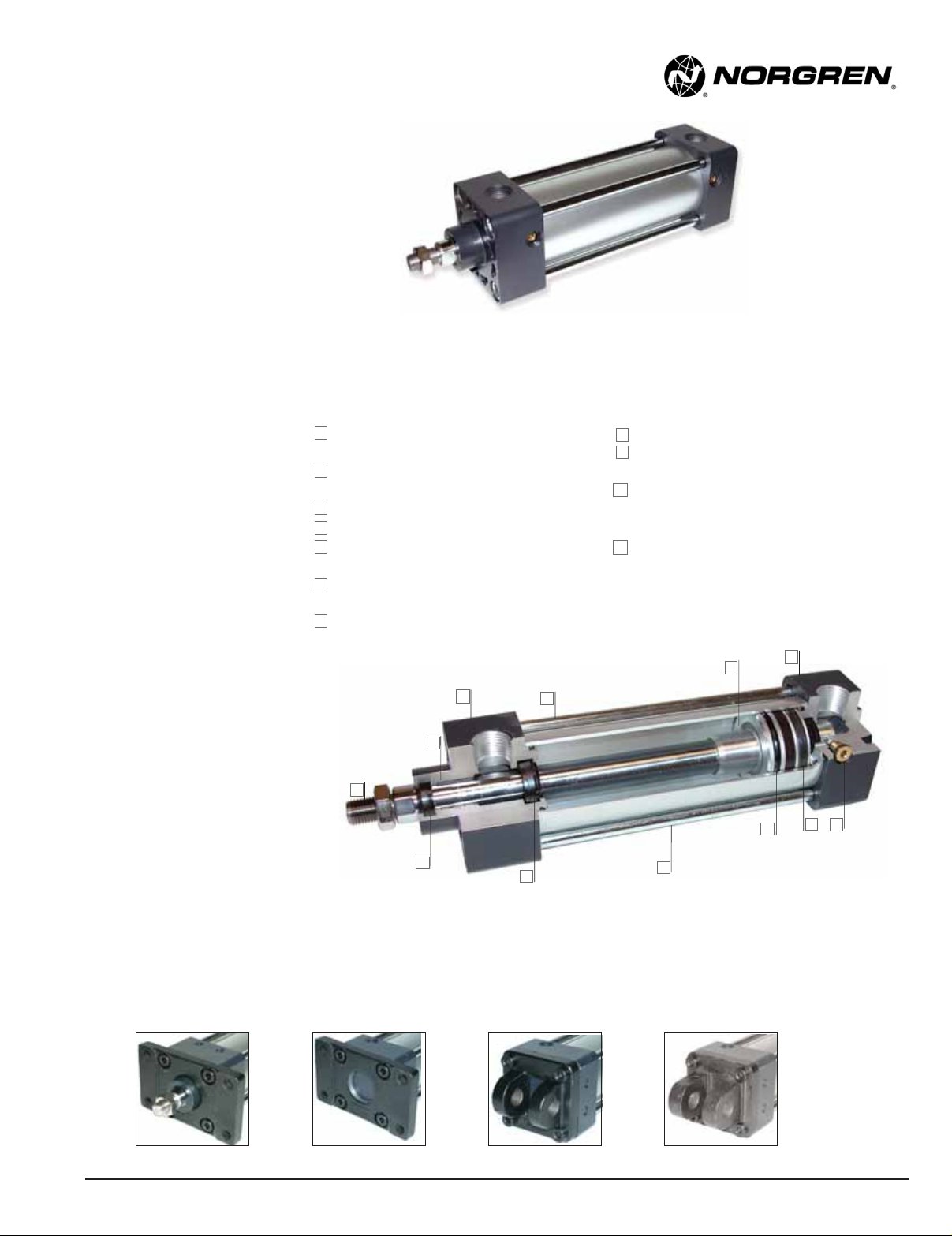
NEN Series NFPA Aluminum Cylinders
1-1/2" to 4" bore sizes
Competitively priced
Magnetic piston standard
Adjustable cushion standard
Sleeve nut construction standard
Stocked strokes
Technical data
Medium:
Filtered compressed air
Operating temperature:
-25°F to 140°F (-5°C to 60°C)
with Viton Seals -23˚F to 300˚F
(-5°C to 150°C)
Operating Pressure:
Minimum 7 psi (.5 bar)
Maximum 140 psi (9.7 bar)
Bore Sizes: 1-1/2", 2", 2-1/2",
3-1/4", 4"
Rod Diameter: 5/8" diameter
piston rod in 1-1/2", 2", 2-1/2"
bore
1" diameter piston rod in 3-1/4"
and 4" bore
Lubrication: None required
Norgren Air Cylinders are rated for
“no lube added” service.
Materials
Head and End Caps:
Die cast aluminum painted for
corrosion protection
Tube: Aluminum alloy, hard coat
anodized
Piston: machined high-strength
aluminum casting.
Rod Bearing: clean metal teflon
composite
Seals: nitrile rod seal/wiper, nitrile
piston seals, nitrile tube end seals
Tie Rods: Nickel plated high-tensile
strength steel, nickel plated
Piston Rod: Hard chrome plated carbon steel,
1
ground and polished.
Head Bearing Housing and cap: Die cast
2
aluminum
Tie-Rods: Nickel plated steel
3
Piston: Machined aluminum .
4
Captive Cushion Needle Adjustment: Provides
5
safe and precise cushion adjustment.
Wear Ring: Teflon® material provides supreme
6
wear and excellent bearing support.
7
Cylinder Tube: Hard anodized aluminum alloy,
with corrosion and score resistant surface finish.
2
11
1
8
10
Piston Rod Wiper/Seal: Abrasion resistant nitrile.
8
Piston Seal: Single Nitrile bi-directional piston
9
seal.
10
Cushion Seal: Nitrile cushion seal is captured
within a precision machined groove allowing for
linear and radial float eliminating misalignment.
Rod Bearing: A composite of Teflon and
11
polyphenylene sulfide and bronze molded to a
steel backing provides low friction and excellent
linear features.
4
3
7
2
6
9
5
NEN “Add-a-mount” flexibility
NEN cylinders allow you to add NFPA mounts shown below when you order the cylinder from the factory, or add the mounts later.
NFPA MF1
N/US 1.5.507.1
NFPA MF2
Our policy is one of continuous research and development.
We reserve the right to amend, without notice, the specifications given in this document.
NFPA MP1
www.norgren.com
NFPA MP2
1/08
Page 2
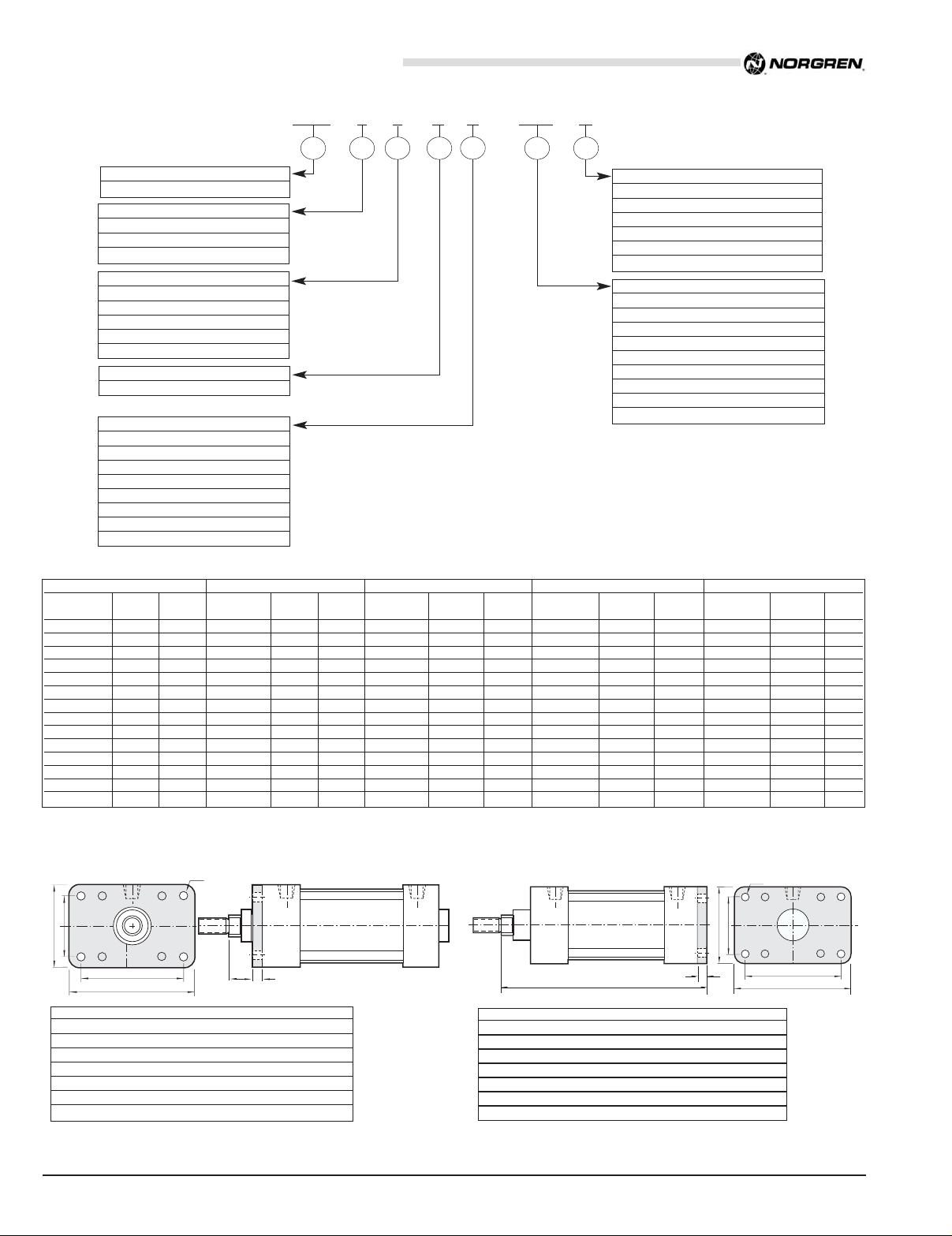
NEN Series NFPA Aluminum Cylinders
F
RE
TF
FB Holes (4)
ZF + Stroke
UF
All Dimensions in Inches (mm)
Cylinder Order Information
NEN 1 C x 4 E – –MP1 V
1 2 3 4
Series
NEN
Piston Rod Threads
Small Male (Solid) (std) 1
Intermediate Thread Male (Solid) 2
Female 3
Bore Single rod
1-1/2" C
2.0" D
2-1/2" E
3-1/4" F
4.0" G
Stroke (whole inches)
All bores 48" max.*
* Conatact factory for strokes longer than 48".
Fraction of Stroke length
0 Blank
0.125" C
0.250 E
0.375 G
0.500 J
0.625 M
0.750 P
0.875 S
5
6 7
Additional Options
Viton® Seals V
Rod Extension RX
Non-standard piston rod thread T
Piston Rod thread extension TX
Stainless steel piston rod S
Stainless steel tie rods SS
Mounting Options**
MS4 (standard) blank
Head Rectangular Flange MF1
Cap Rectangular Flange MF2
Detachable Cap Clevis MP2
Cap Fixed Clevis MP1
Tie Rod Extended both ends MX1
Tie Rod Extended Cap MX2
Tie Rod Extended Head MX3
Side Lug Mount MS2
** For factory installed mounts specify mounting option in
position 6. If no mount required leave position 6 blank.
Mounting kits can be ordered separately
Contact factory for mounting kits, or visit www.norgren.com
Stock Stroke Cylinders
Model Cylinder Stroke Model Cylinder Stroke Model Cylinder Stroke Model Cylinder Stroke Model Cylinder Stroke
Number Bore Number Bore Number Bore Number Bore Number Bore
NEN1C x 1 1-1/2 1.00 NEN1D x 1 2 1.00 NEN1E x 1 2-1/2 1.00 NEN1F x 1 3-1/4 1.00 NEN1G x 1 4 1.00
NEN1C x 2 1-1/2 2.00 NEN1D x 2 2 2.00 NEN1E x 2 2 1/2 2.00 NEN1F x 2 3-1/4 2.00 NEN1G x 2 4 2.00
NEN1C x 3 1-1/2 3.00 NEN1D x 3 2 3.00 NEN1E x 3 2 1/2 3.00 NEN1F x 3 3-1/4 3.00 NEN1G x 3 4 3.00
NEN1C x 4 1-1/2 4.00 NEN1D x 4 2 4.00 NEN1E x 4 2 1/2 4.00 NEN1F x 4 3-1/4 4.00 NEN1G x 4 4 4.00
NEN1C x 5 1-1/2 5.00 NEN1D x 5 2 5.00 NEN1E x 5 2 1/2 5.00 NEN1F x 5 3-1/4 5.00 NEN1G x 5 4 5.00
NEN1C x 6 1-1/2 6.00 NEN1D x 6 2 6.00 NEN1E x 6 2 1/2 6.00 NEN1F x 6 3-1/4 6.00 NEN1G x 6 4 6.00
NEN1C x 8 1-1/2 8.00 NEN1D x 8 2 8.00 NEN1E x 8 2 1/2 8.00 NEN1F x 8 3-1/4 8.00 NEN1G x 8 4 8.00
NEN1C x 10 1-1/2 10.00 NEN1D x 10 2 10.00 NEN1E x 10 2 1/2 10.00 NEN1F x 10 3-1/4 10.00 NEN1G x 10 4 10.00
NEN1C x 12 1-1/2 12.00 NEN1D x 12 2 12.00 NEN1E x 12 2 1/2 12.00 NEN1F x 12 3-1/4 12.00 NEN1G x 12 4 12.00
NEN1C x 14 1-1/2 14.00 NEN1D x 14 2 14.00 NEN1E x 14 2 1/2 14.00 NEN1F x 14 3-1/4 14.00 NEN1G x 14 4 14.00
NEN1C x 16 1-1/2 16.00 NEN1D x 16 2 16.00 NEN1E x 16 2 1/2 16.00 NEN1F x 16 3-1/4 16.00 NEN1G x 16 4 16.00
NEN1C x 18 1-1/2 18.00 NEN1D x 18 2 18.00 NEN1E x 18 2 1/2 18.00 NEN1F x 18 3-1/4 18.00 NEN1G x 18 4 18.00
NEN1C x 20 1-1/2 20.00 NEN1D x 20 2 20.00 NEN1E x 20 2 1/2 20.00 NEN1F x 20 3-1/4 20.00 NEN1G x 20 4 20.00
N/A - 24.00 NEN1D x 24 2 24.00 NEN1E x 24 2 1/2 24.00 NEN1F x 24 3-1/4 24.00 NEN1G x 24 4 24.00
1-1/2" Bore 2.0" Bore 2-1/2" Bore 3-1/4" Bore 4.0" Bore
NFPA (MF1) 03 Head Rectangular Flange Mount
FB Holes (4)
RE
F
TF
UF
Bore 1-1/2" 2" 2-1/2" 3-1/4" 4"
E 2.000 2.500 3.000 3.750 4.500
F .375 .375 .375 .625 .625
FB .313 .375 .375 .438 .438
R 1.428 1.838 2.192 2.758 3.323
TF 2.750 3.375 3.875 4.688 5.438
UF 3.375 4.125 4.625 5.500 6.250
W .625 .625 .625 .750 .750
All dimensions ± .015 unless otherwise noted.
N/US 1.5.507.2
W
We reserve the right to amend, without notice, the specifications given in this document.
NFPA (MF2) 04 Cap Rectangular Flange Mount
Bore 1-1/2" 2" 2-1/2" 3-1/4" 4"
E 2.000 2.500 3.000 3.750 4.500
F .375 .375 .375 .625 .625
FB .313 .375 .375 .438 .438
R 1.428 1.838 2.192 2.758 3.323
TF 2.750 3.375 3.875 4.687 5.438
UF 3.375 4.125 4.625 5.500 6.250
ZF 5.000 5.000 5.125 6.250 6.250
All dimensions ± .015 unless otherwise noted.
Our policy is one of continuous research and development.
www.norgren.com
1/08
Page 3

DD Thds.
4 Places
Both Ends
KK
Thds
NT Tap
ND Depth
XT
SN + Stroke
A
C
VF
LB + Stroke
J
P + StrokeY
øB Bushing
øMM
WF
G
EE NPT (2)
TN
D
(Flats)
R
E Sq.
ZJ + Stroke
AA
NFPA (MS4) Side tap mount standard
NEN Series NFPA Aluminum Cylinders
All Dimensions in Inches (mm)
1/08
øB
KK
Thds.
A Deep
Type 3 Female
C
V
(Optional)
F
øMM
D
Across
Flats
KK
Thds.
ø B
F
øMM
A
C
V
Type 1 Solid
(Small Male)
øB
CC
Thds.
A
C
Type 2 Solid
(Intermediate Thread
Male Optional)
F
øMM
V
Bore 1-1/2" 2" 2-1/2" 3-1/4" 4"
ø Rod 5/8" 5/8" 5/8" 1" 1"
A 0.750 0.750 (19.05) 0.750 (19.05) 1.125 (28.58) 1.125 (28.58)
AA 2.020 2.600 (66.04) 3.100 (78.74) 3.900 (99.06) 4.700 (119.38)
B 1.124 1.124 (28.55) 1.124 (28.55) 1.500 (38.07) 1.499 (38.07)
BA 1.125 (28.58) 1.125 (28.58) 1.125 (28.58) 1.250 (28.58) 1.250 (28.58)
C 0.375 (9.53) 0.375 (9.53) 0.375 (9.53) 0.500 (12.70) 0.500 (12.70)
CC 1/2-20 1/2-20 1/2-20 7/8-14 7/8-14
D 0.562 (14.27) 0.562 (14.27) 0.562 (14.27) 0.875 (22.23) 0.875 (22.23)
DD 1/4-28 5/16-24 5/16-24 3/8-24 3/8-24
E 2.000 (50.80) 2.500 (63.50) 3.000 (76.20) 3.750 (95.25) 4.500 (114.30)
EE 3/8 3/8 3/8 1/2 1/2
G 1.260 (32.00) 1.260 (32.00) 1.300 (33.02) 1.570 (39.88) 1.570 (39.88)
J 1.010 (25.65) 1.060 (26.92) 1.060 (26.92) 1.180 (29.97) 1.180 (29.97)
KK 7/16-20 7/16-20 7/16-20 3/4-16 3/4-16
LB 3.625 (92.08) 3.625 (92.08) 3.750 (95.25) 4.250 (107.95) 4.250 (107.95)
MM 0.625 (15.88) 0.625 (15.88) 0.625 (15.88) 1.000 (25.40) 1.000 (25.40)
NT 1/4-20 5/16-18 3/8-16 1/2-13 1/2-13
ND 0.281 (7.14) 0.438 (11.13) 0.593 (15.06) 0.625 (15.88) 0.625 (15.88)
P 2.360 (59.94) 2.400 (60.96) 2.480 (62.99) 2.720 (69.09) 2.720 (69.09)
R 1.430 (36.32) 1.840 (46.74) 2.190 (55.63) 2.760 (70.10) 3.320 (84.33)
SN 2.250 (57.15) 2.250 (57.15) 2.375 (60.33) 2.625 (66.68) 2.625 (66.68)
TN 0.625 (15.88) 0.875 (22.23) 1.250 (31.75) 1.500 (38.10) 2.063 (52.40)
VF 0.625 (15.88) 0.625 (15.88) 0.625 (15.88) 0.875 (22.23) 0.875 (22.23)
WF 1.000 (25.40) 1.000 (25.40) 1.000 (25.40) 1.375 (34.93) 1.375 (34.93)
XT 1.938 (49.23) 1.938 (49.23) 1.938 (49.23) 2.438 (61.93) 2.438 (61.93)
Y 1.710 (43.43) 1.710 (43.43) 1.750 (44.45) 2.340 (59.44) 2.340 (59.44)
ZJ 4.750 (120.65) 4.750 (120.65) 4.870 (123.95) 5.820 (147.83) 5.820 (147.83)
Our policy is one of continuous research and development.
We reserve the right to amend, without notice, the specifications given in this document.
www.norgren.com
N/US 1.5.507.3
Page 4

NEN Series NFPA Aluminum Cylinders
LB + Stroke
L
øCD
MR
CB
CW CW
Supplied with
Standard Pin
XC + Stroke
LR
XD + Stroke
L
øCD
MR
LR
CB
CW CW
Supplied with
Standard Pin
FL M
All Dimensions in Inches (mm)
MP1 Mount
Bore 1-1/2" 2" 2-1/2" 3-1/4" 4"
CB 0.750 0.750 0.750 1.250 1.250
CD 0.500 0.500 0.500 0.750 0.750
CW 0.500 0.500 0.500 0.625 0.625
L 0.750 0.750 0.750 1.250 1.250
LB 3.625 3.625 3.750 4.250 4.250
LR 0.625 0.625 0.625 0.875 0.875
MR 0.625 0.625 0.625 0.875 0.875
XC 5.375 5.375 5.500 6.875 6.875
MP2 Mount
Bore 1-1/2" 2" 2-1/2" 3-1/4" 4"
CB 0.750 0.750 0.750 1.250 1.250
CD 0.500 0.500 0.500 0.750 0.750
CW 0.500 0.500 0.500 0.625 0.625
FL 1.125 1.125 1.125 1.875 1.875
L 0.750 0.750 0.750 1.250 1.250
LR 0.750 0.750 0.750 1.250 1.250
M 0.500 0.500 0.500 0.875 0.750
MR 0.625 0.625 0.625 0.875 0.875
XD 5.750 5.750 5.875 7.500 7.500
NFPA (MX1) (4) Extended Tie Rods Both Ends Mount
NFPA (MX2) Cap Tie Rods Extended Mount
NFPA (MX3) Head Tie Rods Extended Mount
DD threads
R
C
VF
BB BB
ZB + Stroke
Bore 1-1/2" 2" 2-1/2" 3-1/4" 4"
AA 2.020 2.600 3.100 3.900 4.700
BB 1.000 1.125 1.125 1.375 1.375
C 0.375 0.375 0.375 0.500 0.500
DD 1/4 – 28 5/16 – 24 5/16 – 24 3/8 – 24 3/8 – 24
K 0.250 0.313 0.313 0.375 0.375
R 1.428 1.838 2.192 2.758 3.323
VF 0.625 0.625 0.625 0.875 0.875
ZB 4.875 4.938 5.063 6.000 6.000
All dimensions ± .015 unless otherwise noted.
K
AA
R
N/US 1.5.507.4
We reserve the right to amend, without notice, the specifications given in this document.
Our policy is one of continuous research and development.
www.norgren.com
1/08
Page 5

NEN Series NFPA Aluminum Cylinders
SB thru Dia.
SC - C Bore
SD Deep
XS
C
SU
TS
US
ZB + Stroke
SU
SY
SS + Stroke
SL
SH
ST
ER Radius
L
CE
KK Thds.
CH Across
Hex Flats
CB
CW CW
øCD
RE
TF
UF
F
FB Holes (4)
MS2 Mount
Bore 1-1/2" 2" 2-1/2" 3-1/4" 4"
SB 0.438 0.438 0.438 0.563 0.563
SC 0.690 0.690 0.690 0.800 0.800
SD 0.030 0.030 0.030 0.030 0.030
SH 1.000 1.250 1.500 1.875 2.250
SL 1.875 1.875 1.875 2.500 2.500
SY 0.940 0.940 0.940 1.250 1.250
SS 2.875 2.875 3.000 3.250 3.250
ST 0.620 0.620 0.750 1.000 1.000
SU 0.940 0.940 0.940 1.250 1.250
TS 2.750 3.250 3.750 4.750 5.500
US 3.500 4.000 4.500 5.750 6.500
XS 1.375 1.375 1.375 1.875 1.875
ZB 5.190 5.190 5.310 6.380 6.380
All Dimensions in Inches (mm)
NEN Cylinder Accessories and Kits
RE (rod eye)
RC (rod clevis)
Kit number KK CB CD. CE CH CW ER L
NENC-RC 7/16-20 0.750 0.500 1.500 1.000 0.500 0.500 0.750
NENF-RC 3/4-16 1.250 0.750 2.375 1.250 0.625 0.750 1.250
RC and RE rod accessories come complete with pivot pin and retaining clips.
MS2 Mounting Kit
SB Dia. Thru
SL
ST
SY
SU
Kit number SB SC SD SY ST SU TS US
MK-NENC-MS2 0.41 0.69 0.03 0.94 0.62 0.94 2.75 3.50
MK-NEND-MS2 0.41 0.69 0.03 0.94 0.62 0.94 3.25 4.00
MK-NENE-MS2 0.41 0.69 0.03 0.94 0.75 0.94 3.75 4.50
MK-NENF-MS2 0.52 0.80 0.03 1.25 1.00 1.25 4.75 5.75
MK-NENG-MS2 0.52 0.80 0.03 1.25 1.00 1.25 5.50 6.50
1/08
SC - C bore x SD Deep
TS
US
Our policy is one of continuous research and development.
We reserve the right to amend, without notice, the specifications given in this document.
www.norgren.com
CD
CD
ER Radius
CD
CE
A
KK Thds.
CB
øCD
Kit number KK A CB CD CE ER
NENC-RE 7/16-20 0.750 0.750 0.500 1.500 0.563
NENF-RE 3/4-16 1.125 1.250 0.750 2.063 0.875
NFPA MF1 / MF2 Mounting Kit - MK-NEN-MF1
Kit number UF TF FB E R F
MK-NENC-MF1 3-3/8 2-3/4 5/16 2.00 1.43 3/8
MK-NEND-MF1 4-1/8 3-3/8 3/8 2-1/2 1.84 3/8
MK-NENE-MF1 4-5/8 3-7/8 3/8 3.00 2.19 3/8
MK-NENF-MF1 5-1/2 4-11/16 7/16 3-3/4 2.76 5/8
MK-NENG-MF1 6-1/4 5-7/16 7/16 4-1/2 3.32 5/8
N/US 1.5.507.5
Page 6

NEN Series NFPA Aluminum Cylinders
F
øCD
ER
LR
CB
CW CW
FL
D
G
DD
FL
F
øCD
MR
CB
CW CW
LR
D
G
DD
øCD
LP
LH
E
All Dimensions in Inches (mm)
EB (eye bracket)
LR Radius
F
FL
øCD
M Radius
E
BA
øDD
4 Places
CB
BA
E
NFPA Eye Bracket NENC-EB NENF-EB
BA 1.625 2.563
CB 0.750 1.250
CD 0.500 0.750
DD 0.406 0.531
E 2.500 3.500
F 0.375 0.625
FL 1.125 1.875
LR 0.750 1.250
M 0.500 0.750
All dimensions ± .015 unless otherwise noted.
MP2 Mount kit - MK - NEN - MP2
Kit number CD FL F B CW D ER G DD
MK-NENC-MP2 0.502 1.13 0.38 0.76 0.50 2.00 0.62 1.43 0.28
MK-NEND-MP2 0.502 1.13 0.38 0.76 0.50 2.50 0.62 1.84 0.34
MK-NENE-MP2 0.502 1.13 0.38 0.76 0.50 3.00 0.62 2.19 0.34
MK-NENF-MP2 0.752 1.88 0.63 1.26 0.62 3.75 0.87 2.77 0.41
MK-NENG-MP2 0.752 1.88 0.63 1.26 0.62 4.50 0.87 3.32 0.41
P (pin)
NFPA Pin NEN-5 NEN-7
CD 0.500 0.750
E 0.109 0.125
LH 2.094 2.875
LP 1.875 2.625
MP1 Mount kit - MK-NEN-MP1
Kit number CD FL F B CW D MR G LR DD
MK-NENC-MP1 0.502 0.75 0.38 0.76 0.50 2.00 0.62 1.43 0.62 0.28
MK-NEND-MP1 0.502 0.75 0.38 0.76 0.50 2.50 0.62 1.84 0.62 0.34
MK-NENE-MP1 0.502 0.75 0.38 0.76 0.50 3.00 0.62 2.19 0.62 0.34
MK-NENF-MP1 0.752 1.25 0.63 1.26 0.62 3.75 0.87 2.77 0.87 0.41
MK-NENG-MP1 0.752 1.25 0.63 1.26 0.62 4.50 0.87 3.32 0.87 0.41
MP1 and MP2 kits come complete with mounting hardware, pivot pin and retaining clips.
MX1 Mount kit - MK-NEN-MX1
MX2/MX3 Mount kit-MK-NEN-MX2
DD
A
MX1 Mount Kit-MK-NEN-MX1
Tie Rod extended Both Ends
Kit number DD A B
MK-NENC-MX1 1/4-28 1.375 1.375
MK-NEND-MX1 5/16-24 1.500 1.500
MK-NENE-MX1 5/16-24 1.500 1.500
MK-NENF-MX1 3/8-24 1.812 1.937
MK-NENG-MX1 3/8-24 1.812 1.937
MX2 Mount Kit-MK-NEN-MX2
Tie Rod Extended Cap End
Kit number DD A B
MK-NENC-MX2 1/4-28 N/A 1.375
MK-NEND-MX2 5/16-24 N/A 1.500
MK-NENE-MX2 5/16-24 N/A 1.500
MK-NENF-MX2 3/8-24 N/A 1.937
MK-NENG-MX2 3/8-24 N/A 1.937
MX3 Mount Kit-MK-NEN-MX3
Tie Rod Extended Head End
Kit number DD A B
MK-NENC-MX2 1/4-28 1.375 N/A
MK-NEND-MX2 5/16-24 1.500 N/A
MK-NENE-MX2 5/16-24 1.500 N/A
MK-NENF-MX2 3/8-24 1.812 N/A
MK-NENG-MX2 3/8-24 1.812 N/A
DD
B
WARNING
These products are intended for use in industrial compressed air systems only. Do not use these
products where pressures and temperatures can exceed those listed under
TTeecchhnniiccaall DDaattaa
Before using these products with fluids other than those specified for non-industrial
applications, life-support systems, or other applications not within published specifications,
consult Norgren.
Through misuse, age, or malfunction, components used in fluid power systems can fail in
various modes.
N/US 1.5.507.6
Our policy is one of continuous research and development.
We reserve the right to amend, without notice, the specifications given in this document.
The system designer is warned to consider the failure mode of all component parts used in fluid
.
power systems and to provide adequate safeguards to prevent personal injury or damage to
equipment in the event of such failure.
System designers must provide a warning to end users in the system instructional
manual if protection against a failure mode cannot be adequately provided.
System designers and end users are cautioned to review specific warnings found in instruction
sheets packed and shipped with these products.
www.norgren.com
1/08
 Loading...