

Page 1
Suitable for all cylinder ranges with
A
magnetic piston
Switches can be mounted flush with the
delivered special adaptor
Resistance, reliable switching with a very
fast response time
Particularly suited for use in high levels
of vibration
pnp
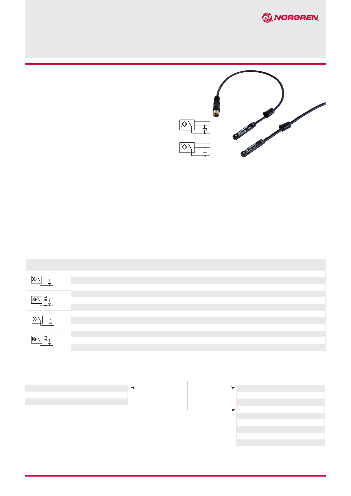
M/50/EAP & M/50/EAN
Magnetically operated switches
Solid state
A
LED indicator as standard
CE verificated
Technical features
Operation:
M/50/EAP (PNP) open collector
output with LED (yellow)
M/50/EAN (NPN) grounded
emitter output with LED (yellow)
Switching voltage (Ub):
10 ... 30 V d.c.
Switching voltage output:
Ub - 2 V
Inducted voltage:
0,5 V
Technical data, standard models
Symbol Voltage
pnp
A
1
3
pnp
A
4
npn
A
3
1
npn
A
4
(V d.c.)
10 ... 30 150 PNP -40 ... +80 • IP67 — 2, 5 or 10 PVC 3 x 0,12 37 M/50/EAP/*V
+
BN
BU
10 ... 30 150 PNP -40 ... +80 • IP68 — 5 PUR 3 x 0,14 37 M/50/EAP/5U
BK
10 ... 30 150 PNP -40 ... +80 • IP67 Plug M8 x 1 0,3 PVC 3 x 0,14 16 M/50/EAP/CP *1)
+
BN
BU
10 ... 30 150 PNP -40 ... +80 • IP67 Plug M12 x 1 0,3 PVC 3 x 0,14 16 M/50/EAP/CC *1)
BK
10 ... 30 150 NPN -40 ... +80 • IP67 — 2, 5 or 10 PVC 3 x 0,12 37 M/50/EAN/*V
BU
+
BN
BK
10 ... 30 150 Closer -40 ... +80 • IP67 Plug M8 x 1 0,3 PVC 3 x 0,14 16 M/50/EAN/CP *1)
+
BU
BN
BK
Switching current (see graph):
150 mA max.
Switching power:
4,5 W max.
Response time:
< 0,5 ms
Operating frequency:
5 kHz
Protection rating (EN 60529):
IP 67 (standard)
IP 68 for type: M/50/EAP/5U
Current
max. (mA)
Function
Temperature
(°C)
npn
Operating temperature:
-40 ... +80°C (IP67 & IP68)
Cable type:
PVC 3 x 0,12 (standard)
PUR 3 x 0,14 (M/50/EAP/5U)
Cable length:
2, 5 and 10 m
Electromagnetic compatibility
according to:
EN 60947-5-2
LED Protection
class
Features Cable length
(m)
Materials:
Body: plastic
Cable: see table below
Cable
type
Weight
(g)
Model
* Insert cable length
*1) Plug-in connector see page 2
Color code: BK = black, BN = brown, BU = blue
Options selector
Function Substitute
PNP
NPN
1/14 1999-4001c
Our policy is one of continued research and development. We therefore reserve the right to amend,
without notice, the specifications given in this document. © 2014 Norgren GmbH
M/50/EA˙/˙˙˙
Cable Substitute
P
N
PVC (standard)
Polyurethan (only for M/50/EAP/5U)
Cable length/plug Substitute
2 m
5 m
10 m
Cable (0,3 m) with plug M8x1
Cable (0,3 m) with plug M12x1
V
U
2
5
10
CP
CC
N/en 4.3.007.01
Page 2
M/50/EAP & M/50/EAN
Switching current and switching voltage
mA
150
0
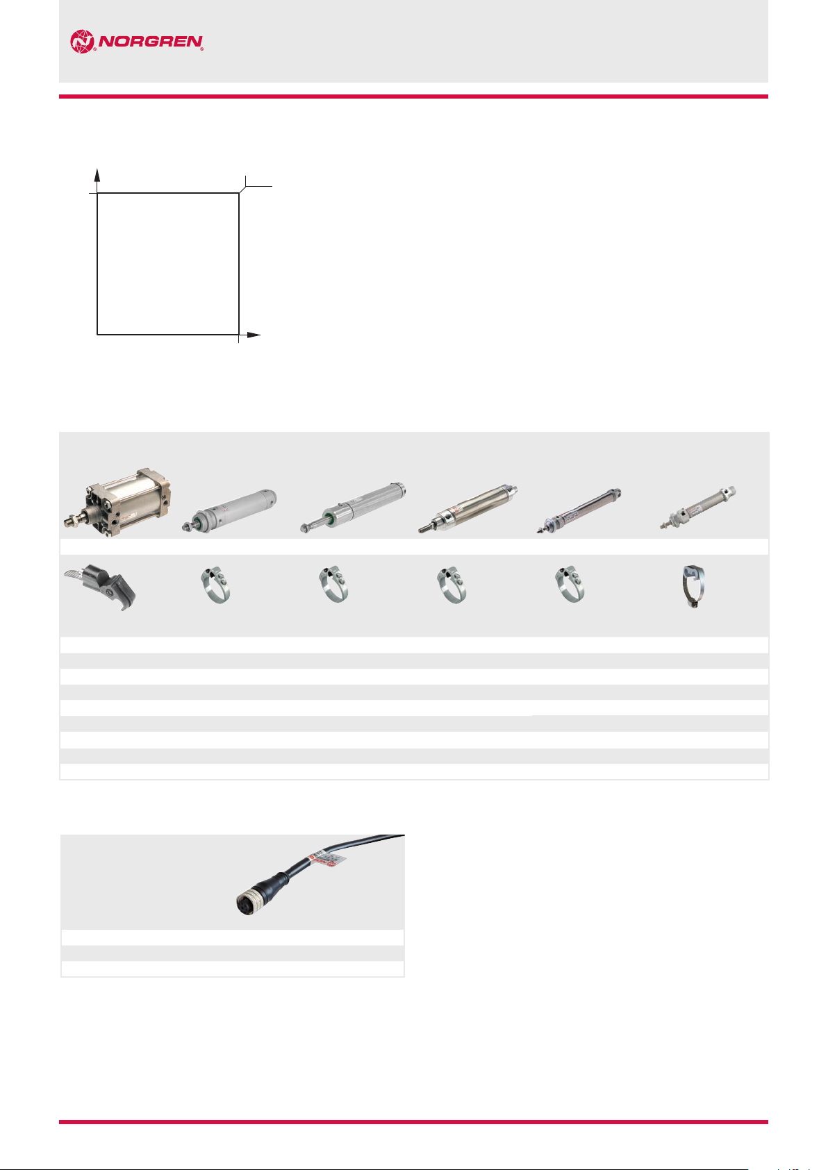
Mounting elements for magnetic switches
Cylinder with external tie rods
RA/8000/M, KA/8000/M
RA/28000/M, RM/900/M
Roundline cylinder
RM/55401/M
4,5 W
V
d.c.
30
Roundline cylinder
KM/55001/M, VSM/55640/N2
Roundline cylinder
R./57100/M, R./57200/M
R./57300/M
Roundline cylinder
< 25 mm stroke
RM/8000/M, KM/8000/M
RM/28000/M
Roundline cylinder
> 25 mm stroke
RM/8000/M, KM/8000/M
RM/28000/M
Mounting elements
Cylinder
Ø(mm) Model
32 ... 200 QM/27/2/1 32 QM/33/432/22 32 QM/33/432/22 10 QM/33/010/22 10 QM/33/010/22 10 QM/33/010/23
Dimensions see relevant cylinder sheets.
Cylinder
Ø(mm) Model
40 QM/33/440/22 40 QM/33/440/22 12 QM/33/012/22 12 QM/33/012/22 12 QM/33/016/23
50 QM/33/450/22 50 QM/33/450/22 16 QM/33/016/22 16 QM/33/016/22 16 QM/33/016/23
63 QM/33/463/22 63 QM/33/463/22 20 QM/33/020/22 20 QM/33/020/22 20 QM/33/020/23
80 QM/33/480/22 80 QM/33/080/22 25 QM/33/025/22 25 QM/33/025/22 25 QM/33/025/23
100 QM/33/410/22 100 QM/33/100/22 32 QM/33/032/22
Cylinder
Ø(mm) Model
125 QM/33/125/22 40 QM/33/040/22
Cylinder
Ø(mm) Model
50 QM/33/050/22
63 QM/33/063/22
Cylinder
Ø(mm) Model
Cylinder
Ø(mm) Model
Accessories
Plug-in connector cable with nut
Outer cover Cable length Weight (kg) Connector Model
PVC 3 x 0,25 5 m 0,18 M8 x 1 M/P73001/5
PUR 3 x 0,25 5 m 0,18 M8 x 1 M/P73002/5
PUR 3 x 0,34 5 m 0,21 M12 x 1 M/P34594/5
N/en 4.3.007.02
Our policy is one of continued research and development. We therefore reserve the right to amend,
without notice, the specifications given in this document. © 2014 Norgren GmbH
1999-4001c 1/14
Page 3

Dimensions
M/50/EAP/*V, M/50/EAN/*V
Cable length L = 2, 5 or 10 m
M/50/EAP & M/50/EAN
A-B
1
5,1
ø 6,4
M/50/EAP/CP, M/50/EAN/CP
A-B
5,1
1
ø 6,4
M/50/EAP/CC
A-B
1
5,1
ø 6,4
+30
L
30
1,5
30
1,5
30 47,5
1,5
A
B
±15
300
A
B
±15
300
A
2
31,5 ... 36
±4
42
X
4 BK
X
3
1 BN
4 BK
X
1 BN
4
3 BU
X
3 BU
1
Fixing screw
2
Color code
BK = black
BN = brown
BU = blue
3
Plug M8 x 1
4
Plug M12 x 1
Warning
These products are intended for use in industrial control systems only.
Do not use these products where values can exceed those listed under
‘Technical Features/Data’.
Before using these products for non-industrial applications, lifesupport systems, or other applications not within published specifications, consult NORGREN.
Through misuse, age, or malfunction, components used in control
systems can fail in various modes.
The system designer is warned to consider the failure modes of all
1/14 1999-4001c
Our policy is one of continued research and development. We therefore reserve the right to amend,
without notice, the specifications given in this document. © 2014 Norgren GmbH
component parts used in control systems and to provide adequate
safeguards to prevent personal injury or damage to equipment in the
event of such failure.
System designers must provide a warning to end users in the system
instructional manual if protection against a failure mode cannot be
adequately provided.
System designers and end users are cautioned to review specific
warnings found in instruction sheets packed and shipped with these
products.
N/en 4.3.007.03
 Loading...