

Page 1
Littleton, CO USA Phone 303-794-2611 Fax 303-795-9487
ALE-14-A
Section 14
Contents
Lubricator Overview . . . . . . . . . . . . . . . . . . . . . . . . . . . . . . . . . . . . ALE-14-B
L07 Miniature Micro-Fog® Lubricator 1/8" and 1/4" Ports . . . . . . . ALE-14-2
L72 Excelon Micro-Fog and Oil-Fog Lubricator
1/4" and 3/8" Ports . . . . . . . . . . . . . . . . . . . . . . . . . . . . . . . . . . . ALE-14-4
L73 Excelon Micro-Fog and Oil-Fog Lubricators
1/4", 3/8", and 1/2" Ports . . . . . . . . . . . . . . . . . . . . . . . . . . . . . . ALE-14-6
L74 Excelon Micro-Fog and Oil-Fog Lubricators
3/8", 1/2", and 3/4" Ports. . . . . . . . . . . . . . . . . . . . . . . . . . . . . . . ALE-14-8
L64 Olympian Plus Micro-Fog and Oil-Fog Lubricators
1/4", 3/8", 1/2", and 3/4" Ports . . . . . . . . . . . . . . . . . . . . . . . . . . ALE-14-10
L68 Olympian Micro-Fog and Oil-Fog Lubricator
3/4", 1, 1-1/4", and 1-1/2" Ports. . . . . . . . . . . . . . . . . . . . . . . . . ALE-14-12
L17 Micro-Fog and Oil-Fog Lubricators
3/4", 1", 1-1/4" and 1-1/2" Ports . . . . . . . . . . . . . . . . . . . . . . . . ALE-14-14
10-028 Oil-Fog Lubricator 1-1/2" Port . . . . . . . . . . . . . . . . . . . . . . ALE-14-16
10-076 Oil-Fog Lubricator 2" Port . . . . . . . . . . . . . . . . . . . . . . . . . ALE-14-18
10-015 Micro-Fog Machine Bearing Lubricator,
8 to 32 Bearing Inch Ratings, 1/4" Port . . . . . . . . . . . . . . . . . . ALE-14-20
Lubricators
Compressed air tool lubricators are
available in modular or inline
models in port sizes from 1/8" to 2".
Machine bearing lubricators are
available in 8 to 32 inch ratings.
L07
L64M/C
L68
L17 10-028
10-076
10-015
L74M/C
L73M/C
L72M/C
Page 2
Lubricator Overview
Littleton, CO USA Phone 303-794-2611 Fax 303-795-9487
ALE-14-B
1.1 GENERAL OVERVIEW
Norgren manufactures two main types of lubricators:
Oil-Fog and Micro-Fog. These units are mounted
directly into the pipe and add small amounts of oil
to the air flowing through them.
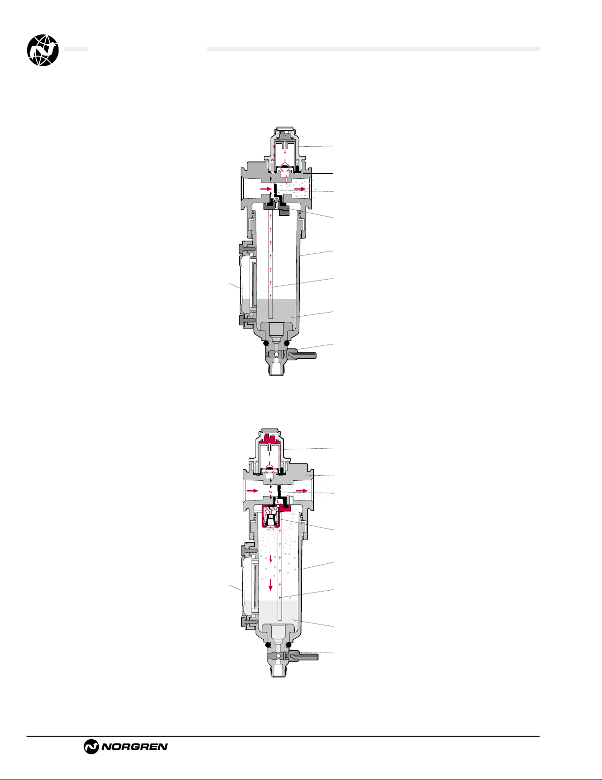
Oil Fog-Lubricators:
All the oil droplets seen in the sight dome are added
directly into the air flow. This results in relatively
large oil droplets passing downstream, suitable for
heavy lubrication applications eg single cylinders
and tools. Most competitive in line lubricators are
of the Oil-Fog type.
Micro-Fog Lubricators:
The oil droplets seen in the sight dome are atomized
and collected in the area above the oil in the bowl.
The smaller lighter particles are drawn into the air
flow and pass downstream.
As a result typically only 10% of the oil
seen as drops in the sight dome is passed
downstream. The remainder falls back into the oil
reservoir. Consequently, drip rate settings are
somewhat higher than their Oil-Fog equivalent. This
makes setting much easier, particularly in low flow
applications.
The fine Micro-Fog oil particles can travel
long distances through complex pipe work making
Micro-Fog lubricators suitable for multiple valve
and cylinder circuits.
1.2 WHAT ARE THE
DIFFERENCES BETWEEN
MICRO-FOG AND OIL-FOG?
1.2.1 Oil-Fog:
• Large oil particles not as fine as micro-fog.
• All oil drips seen in sight domes are
delivered downstream.
• For applications over short distances.
• Should be mounted at same level or higher
than device being lubricated.
• Standard bowls can be filled under
pressure. (Not on rapid cycle units).
• Suitable for heavy lubrication applications
eg single large cylinders and tools.
• Has a flow sensor which provides constant
oil output density for varying flows.
OIL-FOG LUBRICATOR
MICRO-FOG LUBRICATOR
1.2.2 Micro-Fog:
• Small oil particles; less than 2 micron.
• Only 10% of ‘drip rate’ is delivered
downstream as active lubricant (remainder
is returned to main oil reservoir).
• High drip rates make drip setting easier in
low flow applications.
• Can be mounted above or below the point
of application.
• Cannot be filled without shutting off
upstream air (unless a quick fill cap or
remote fill device is used).
• For use with lengthy air lines, multiple
valve and cylinder circuits.
• Has a flow sensor to provide an almost
constant oil output density for varying
flows.
1.2.3 Can Oil-Fog and Micro-Fog Units be
Converted?
Generally not, simply changing a green (Oil-Fog)
sight dome for a red (Micro-Fog) sight dome does
not change the function.
Some lubricators are designed around a
cartridge insert. In this case it may be possible to
swap the cartridge and sight domes to change the
function.
Metal bowl
sight glass
Sight
dome
Body
Flow
sensor
Check
valve
Bowl
Syphon
tube
Oil
Drain
(optional)
Sight
dome
Metal bowl
sight glass
Body
Flow
sensor
Generator
assembly
Bowl
Syphon
tube
Oil
Drain
(optional)
Page 3
Lubricator Overview
Littleton, CO USA Phone 303-794-2611 Fax 303-795-9487
ALE-14-C
1.4 SETTING LUBRICATOR
DRIP RATES
1.4.1 What is the Correct Drip Rate Setting?
The drip rate will depend on the application, the
amount of lubrication required, the flow through the
lubricator and the lubricator type. In Micro-Fog
lubricators only 10% of the droplets in the sight
dome are carried downstream. The drip rate in
Micro-Fog lubricators therefore tends to be much
higher.
The following table can be used to estimate
drip rate for required flow. This is very much a rule
of thumb. In practice it is necessary to fine tune the
oil drip rate in each application.
Typical Drip Rate Typical Drip Rate Approx
per Minute per Minute Flow
Micro-Fog Oil-Fog scfm
(dm3/s)
20 2 10 (5)
40 4 20 (10)
60 6 30 (15)
80 8 40 (20)
100 10 50 (25)
120 12 60 (30)
1.3.2 Can the Drip Rate be Shut Off?
In lubricators with needle valve type sight dome,
yes.
Some Norgren sight domes use a felt pad
which is soaked in oil at the point where the drops
are formed. With this type of sight dome the oil
droplets cease once the felt pad dries out.
With the new style dome (L72/73/74 and
L07) complete shut off is not possible. Minimum
adjustment for the drip rate is around 1 drop per
minute.
1.5 FILLING METHODS
1.5.1 Oil-Fog and Micro-Fog Lubricators:
The standard Oil-Fog lubricators can be filled under
pressure ie without switching off the upstream air.
When a fill plug is removed a check valve in the
lubricator body isolates the inlet pressure from the
bowl and the reservoir will depressurize. The
lubricator can then be filled with oil. When the fill
plug is replaced, the reservoir will re-pressurize.
The standard Micro-Fog unit can only be
filled without isolating the upstream pressure if a
remote fill or quick fill nipple accessory is fitted. To
remove the fill plug of a Micro-Fog lubricator whilse
under pressure can be dangerous. If in doubt shut
off the upstream air!
1.5.2 Remote Fill Devices:
The remote oil fill system provides a means of filling
from a remote fill point, a single lubricator or a bank
of lubricators manifolded together. The remote fill
point may be connected to a portable reservoir or to
a centralized, permanent reservoir. A portable
reservoir permits the use of different lubricants in
different groups of lubricators to suit the
requirements of the machinery being lubricated. The
lubrication oil must be fed in at a higher pressure
than exists in the bowl.
The devices are NOT intended for
connection to an oil feed line which is under
constant pressure from a pump or pressurized
reservoir. The device cannot reset until the pressure
is removed. Such lines are a potential safety hazard
if they should leak or become broken.
1.5.3 Quick Fill Nipples:
The quick fill system is an alternative which allows
ease of filling a single Micro-Fog or Oil-Fog
lubricator without switching off the mains air (on
some units the quick fill nipple replaces the filler
plug).
To fill the lubricator, a quick fill connector
piped to a portable oil reservoir is snapped in place
over the quick fill nipple. The main oil reservoir can
now be pumped (or pressurized) to a pressure
greater than the lubricator bowl and the lubricator
filled.
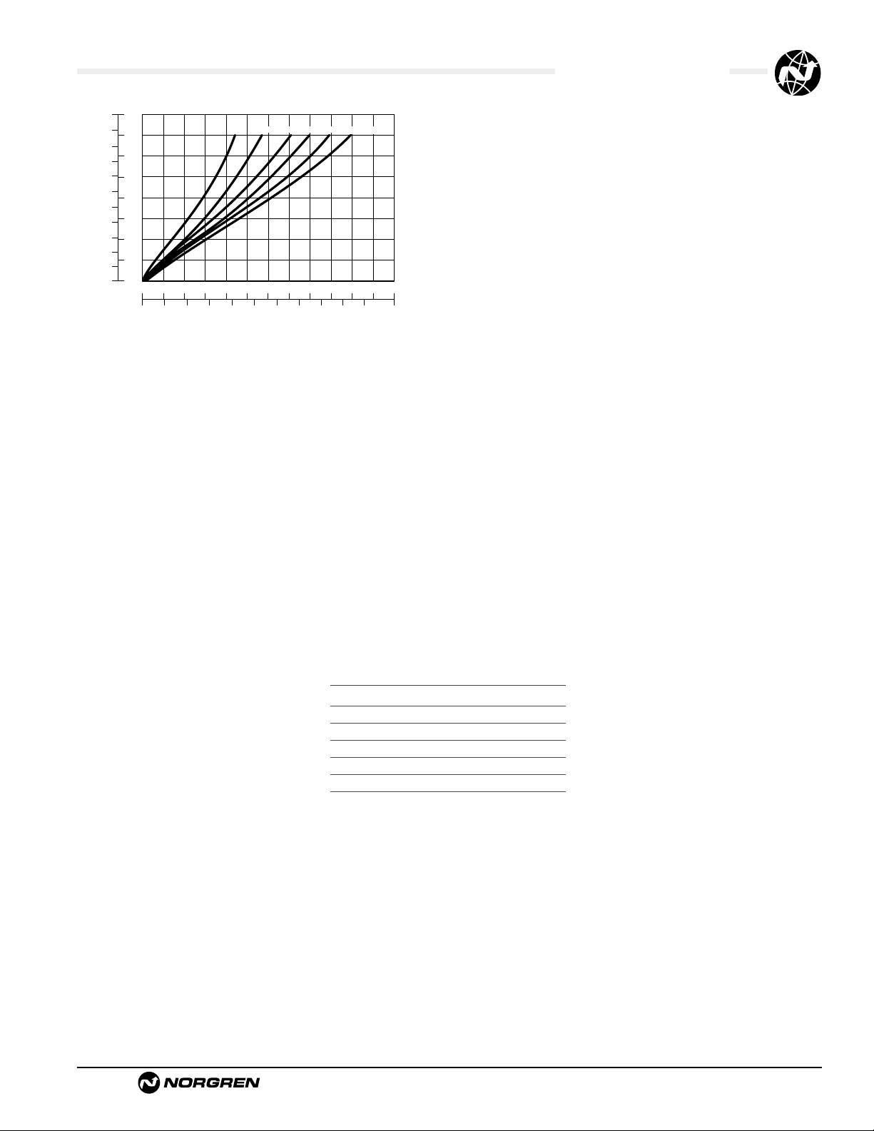
1.3 LUBRICATOR SIZING
Lubricators are sized by downstream flow
requirements. An analysis of air flow use must be
made. After determining how much air flow is
needed, a lubricator can be chosen. Manufacturers’
curves will be like the one shown. For example, 50
scfm of 90 psig lubricated air is required. Enter the
curve on the horizontal axis at the required flow.
Read up to intersect the 90 psig line. Read the
pressure drop on left, vertical axis as approximately
2.3 psid. Pressure drop should be less than 5 psid.
If pressure drop is more than 5 psid, choose a larger
lubricator.
Always be sure that the lubricants in your system are
compatible with the materials in the lubricator you
choose. This is especially important for plastic
lubricator reservoirs. If in doubt, check with the
factory or use a metal reservoir.
Flow Characteristics
bar
psig
.5
7
6
.4
5
.3
4
3
.2
Pressure Drop
2
.1
1
0
0
0
01020304050
20 40 60 80 100 120 140 160 180 200 scfm
35 60 90 120 160 180 psig
60 70 80 90 100
Air Flow
dm 3/s
Page 4

Lubricator Overview
Littleton, CO USA Phone 303-794-2611 Fax 303-795-9487
ALE-14-D
1.6 OPTIONS AND
ACCESSORIES
1.6.1 Where can Liquid Level Switches be
Fitted?
Liquid level detection methods can be attached to
the 1 quart bowl and 2 & 5 gallon tanks.
1.6.2 Where can Remote Fill and Liquid Level
Switches be Fitted?
The smaller bowls, L73 and up, are all capable of
either remote fill or liquid level detection (but not
both at the same time!). The 2 quart and 2 & 5
gallon tanks only can have the liquid level switches
fitted.
1.6.3 How do Liquid Level Switches Work?
Liquid level switches are bipolar reed switches
which change state when the float rises and falls.
Liquid level switches are normally
connected to give an electrical signal when the float
falls (ie when the liquid level is too low). In critical
applications the logic could be reversed. Maximum
and minimum settings are possible too.
1.7 LARGE TANKS/RESERVOIRS
1.7.1 Which Units have Large Tanks/Reservoirs?
All units in basic 1/2” and above have optional
larger bowls/tanks.
Olympian Plus and Excelon 74 are limited
to 1 quart as standard. For 2 and 5 gallon capacity
use 15/17 Series, or the 10-028/-076 (2”)
lubricators.
1.8 APPLICATION SPECIFIC
UNITS
1.8.1 Do we Make Bearing Lubricators?
These are aerosol type lubricators. These
lubricators use air to get the oil to the point of
lubrication, however the tool or application is not
powered by the air. Although produced by Norgren,
systems for their application are designed and sold
by Engineering and General Lubrication Systems.
1.8.2 What is a Fixed Venturi (Bi-Directional)
Lubricator?
Standard Norgren lubricators use a flow sensor to
achieve constant oil density with varying flows. In
some applications high flow is more important than
constant density and a fixed venturi can be used
instead of a flow sensor. It may also be useful in
systems with rapid cycling. Consult Air Line for
more details.
1.9 OILS
1.9.1 What Oils are Recommended?
Recommended oils fall into 2 categories:1 Oils recommended for use with all Norgren
units (valves, cylinders, fittings and FRL’s).
2 Oils which can be used with Norgren
lubricators but not necessarily with other
Norgren equipment.
Refer to ALE-29-2 for recommended lubricants.
1.9.2 Can Non-Recommended Oils be Used?
Some oils can be tested for suitability, but Norgren
cannot be responsible for use of non-recommended
lubricants.
Page 5
Lubricators Overview
Littleton, CO USA Phone 303-794-2611 Fax 303-795-9487
ALE-14-E
Problem
No Drip Rate
Oil Foaming
Oil Emulsified
Drip Rate changes after setting
Possible Cause
Oil adjustment knob fully clockwise.
Low oil level.
Airflow through lubricator too low.
Blocked oil filter screen.
Air leaks.
Over aeration.
Water in lubricator.
Fade.
Remedy
Readjust knob.
Check oil level.
Use smaller size lubricator.
Remove bowl and sight feed adjustment dome and
clear syphon tube.
Remove sight feed adjustment dome and clean or
replace screen located in dome assembly.
Check bowl, filler plug and sight dome seals.
Tighten if necessary.
Check bowl seals for slight leaks.
Fit filter immediately upstream.
Readjust drip rate.
1.10 SIMPLE LUBRICATOR TROUBLESHOOTING
Page 6
See Section ALE-25 for Accessories
Littleton, CO USA Phone 303-794-2611 Fax 303-795-9487
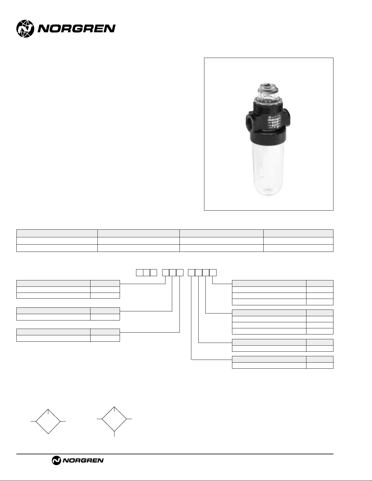
L07
● Compact design
● Provides air line lubrication to one or more air driven
tools or other devices
● Nearly constant oil density output with varying air
flow
● All around (360°) visibility of the sight-feed dome
simplifies installation and adjustment
● Screw-on bowl reduces maintenance time
● Can be disassembled without the use of tools or
removal from the air line
Miniature Series 07 Micro-Fog
Lubricator 1/8" and 1/4" Port Sizes
ALE-14-2
ISO Symbols
No drain Manual drain
Port Size Model Numbers Flow scfm (dm3/s)* Weight lbs (kg)
1/8" L07-100-MPAA 10 (5.0 dm3/s) 0.28 (0.13)
1/4" L07-200-MPAA 14 (6.7 dm3/s) 0.28 (0.13)
Ordering Information. Models listed include PTF threads and transparent bowl with manual drain.
* Approximate flow at 90 psig (6.3 bar) inlet pressure and 7 psig (0.5 bar) pressure drop.
Alternative Models
Port Size Substitute
1/8" 1
1/4" 2
Threads Substitute
PTF A
ISO Rc taper B
ISO G parallel G
Option Substitute
Not applicable 0
Bowl and Drain Substitute
Transparent without drain Q
Metal with drain M
Transparent with drain A
Option Substitute
Not applicable 0
Flow Substitute
Unidirection P
Lubricator Type Substitute
Micro-Fog M
-
★PM★★
★
-
0★L 7
Page 7
L07 Lubricators
Littleton, CO USA Phone 303-794-2611 Fax 303-795-9487
ALE-14-3
All Dimensions in Inches (mm)
Technical Data
Fluid: Compressed air
Maximum pressure
Transparent bowl: 150 psig (10 bar)
Metal bowl: 250 psig (17 bar)
Operating temperature*
Transparent bowl: 0° to 125°F (-20° to 50°C)
Metal bowl: 0° to 175°F (-20° to 80°C)
* Air supply must be dry enough to avoid ice formation at temperatures below
35°F (2°C)
Start point (i.e. minimum flow required for lubricator operation): 0.5 scfm
(0.24 dm3/s) at 90 psig (6.3 bar) inlet pressure
Typical flow at 90 psig (6.3 bar) inlet pressure at 7 psig (0.5 bar) pressure drop:
1/8" ports: 10 scfm (5 dm
3
/s)
1/4" ports: 14 scfm (6.7 dm
3
/s)
Nominal bowl size: 1 fluid ounce (31 ml)
Drain connection:Will fit 1/8-27 and 1/8-28 pipe thread
Recommended lubricants: See Section ALE-29.
Materials
Body: Zinc
Bowl
Transparent: Polycarbonate
Metal: Zinc
Sight-feed dome:Transparent nylon
Elastomers: Neoprene & nitr ile
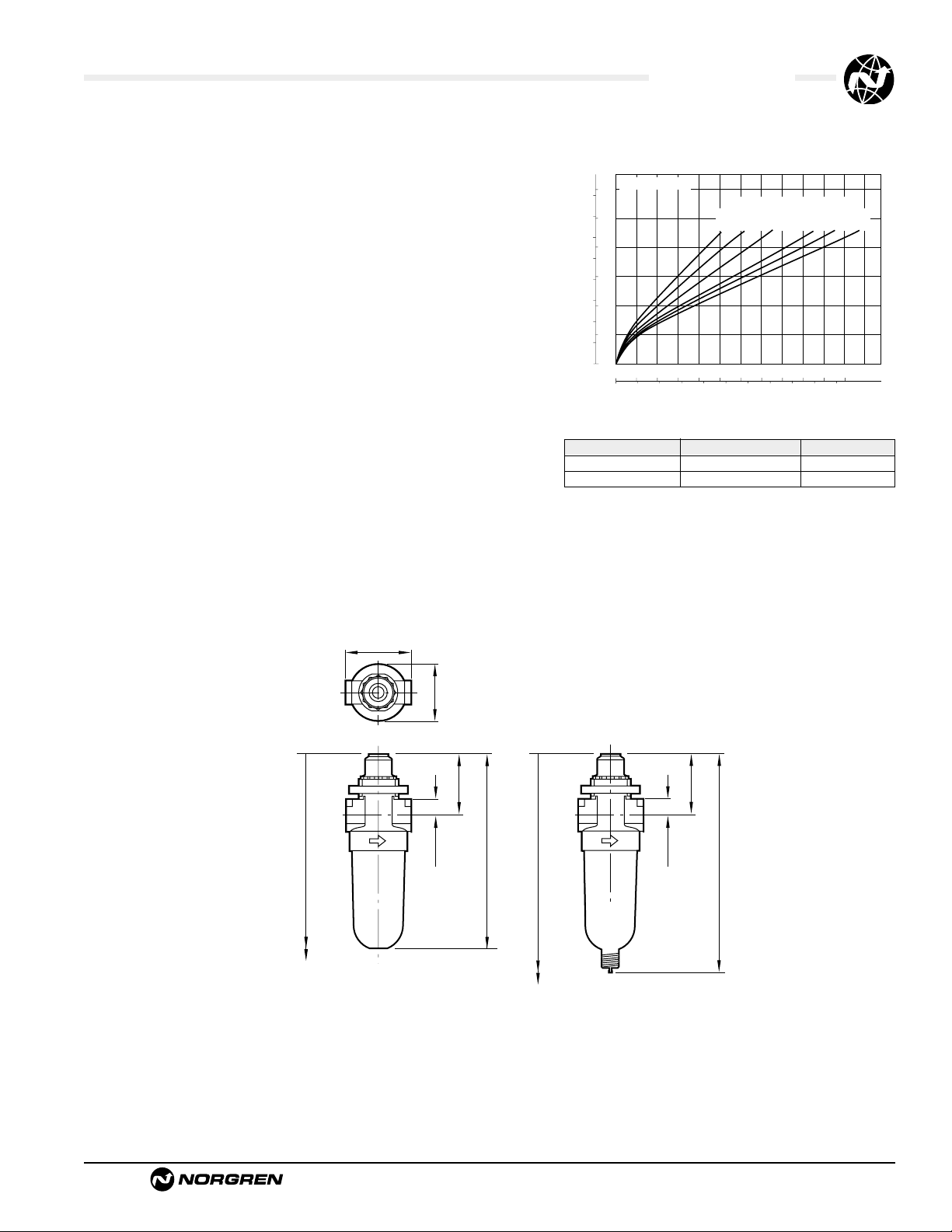
Typical Performance Characteristics
1.63 (41)
1.45 (37)
7.21 (183)†
0.38 (10)
1.65 (42)
4.72 (120)
Manua Drai
Without Drai
7.60 (193)†
0.38 (10)
1.65 (42)
5.12 (130)
† Minimum clearance to remove bowl.
Service Kits
Item Type Part number
Service kit Seal and o-ring 3795-03
Replacement drain Manual 773-03
Service kit includes o-ring, seal, and bowl o-ring.
Panel mounting hole diameter: 1.9" (30 mm)
Maximum panel thickness:0.25” (6 mm)
PORT SIZE: 1/4"
psid
bar d
0.8
10
0.6
8
6
0.4
PRESSURE DROOP
4
0.2
2
0
0
0 4 8 12 16 20 24 scfm
0 2 4 6 8 10 dm3/s
FLOW CHARACTERISTICS
INLET PRESSURE: psig (bar g)
36
23
(1.6)
(2.5)
AIR FLOW
(4.0)
58
91
(6.3)
116
150
(10)
(8)
n
n
Page 8
See Section ALE-25 for Accessories
Littleton, CO USA Phone 303-794-2611 Fax 303-795-9487
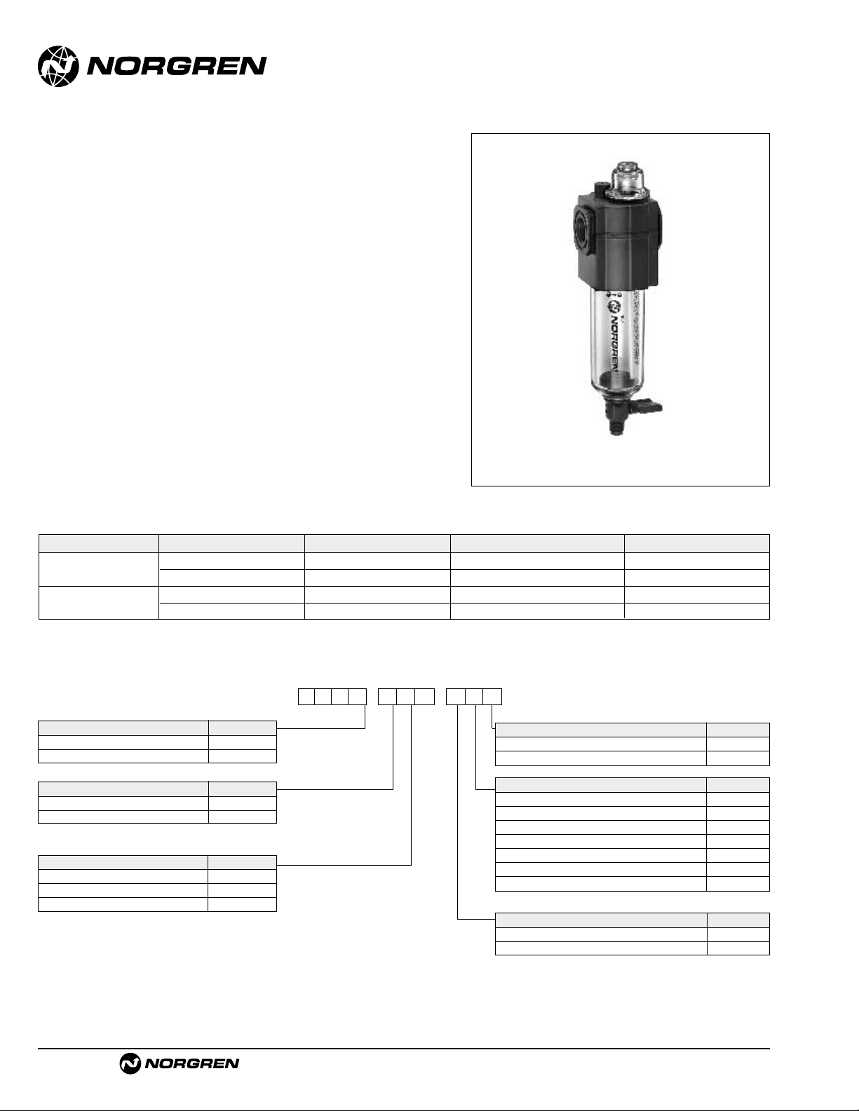
L72M, L72C
● Excelon design allows in-line or modular installation
● Quick release bayonet bowl
● Flow sensor provides a consistent oil/air ratio over a
wide range of flows
● Highly visible, prismatic liquid level indicator lens on
metal bowls
● All round (360°) visibility of sight-feed dome for ease
of drip rate setting
● Modular installations with Excelon 72, 73, and 74
series can be made to suit particular applications
Use Micro-Fog models in applications with one or more points of
lubrication.
Use Oil-Fog models to lubricate a single tool, cylinder or other air
driven device.
Excelon 72 Micro-Fog and Oil-Fog
Lubricator 1/4",3/8" Port S iz es
ALE-14-4
Alternative Models
L 7 2
-
★ ★ ★
-
★
P
★ ★
Type Substitute
Oil-Fog C
Micro-Fog M
Threads Substitute
PTF A
ISO Rc taper B
ISO G parallel G
Port Size Substitute
1/4" 2
3/8" 3
Options Substitute
None N
Pyrex dome P†
Drain Substitute
Closed bottom bowl E
1/4 turn manual Q
† For use with metal bowl with Pyrex sight glass
Bowl Substitute
Short metal with plastic liquid level indicator D
Short metal with Pyrex liquid level indicator R
Long metal with plastic liquid level indicator E
Long metal with Pyrex liquid level indicator U
Short transparent without guard T
Long transparent without guard L
Long transparent with guard W
Ordering Information. Models listed include PTF threads, manual drain, and long transparent bowl without guard.
* Typical flow with 90 psig (6.3 bar) inlet pressure and a pressure drop of 7 psig (0.5 bar).
Type Main Port Size Model Number Flow* scfm (dm3/s) Weight lb (kg)
†
Micro-Fog 1/4" L72M-2AP-QLN 51 (24) 1.1 (0.49)
3/8" L72M-3AP-QLN 51 (24) 1.1 (0.49)
Oil-Fog 1/4" L72C-2AP-QLN 51 (24) 1.1 (0.49)
3/8" L72C-3AP-QLN 51 (24) 1.1 (0.49)
Page 9

L72M/C Lubricators
Littleton, CO USA Phone 303-794-2611 Fax 303-795-9487
ALE-14-5
All Dimensions in Inches (mm)
Technical Data
Fluid: Compressed air
Maximum pressure:
Transparent bowl: 150 psig (10 bar)
Metal bowl: 250 psig (17 bar)
Operating temperature*:
Transparent bowl: 0° to 125°F (-20° to 50°C)
Metal bowl: 0° to 150°F (-20° to 65°C)
* Air supply must be dry enough to avoid ice formation at temperatures below 35°F (2°C).
Start point (i.e. minimum flow required for lubricator operation) at 90 psig (6.3 bar)
inlet pressure:
Micro-Fog: 2.0 scfm (0.94 dm3/s)
Oil-Fog: 1.0 scfm (0.47 dm3/s)
Typical flow at 90 psig (6.3 bar) inlet pressure and 7 psig
(0.5 bar) pressure drop: 51 scfm (24 dm
3
/s)
Nominal reservoir capacity:
Short bowl: 1.9 fluid ounce (56 ml)
Long bowl: 2.2 fluid ounce (65 ml)
Manual drain connection:Will fit 1/8-27 and 1/8-28 pipe thread
Recommended lubricants: See Section ALE-29.
Materials:
Body: Zinc
Reservoir:
Transparent: Polycarbonate
Guard for transparent reservoir: Zinc
Metal: Zinc
Metal reservoir liquid level indicator lens:
Transparent nylon
Sight-feed dome:Transparent nylon
Elastomers: Neoprene, nitrile, and Geolast®
Typical Performance Characteristics
** Minimum clearance required to remove bowl.
† Optional pyrex sight-feed dome.
Service Kits
Item Type Part Number
Service kit Seal and gasket 4382-500
Liquid level lens kit Prismatic 4380-030
Replacement drains 1/4 turn manual 619-50
Service kit includes plug o-ring, sight-feed dome seal, manual drain
o-ring and bowl o-ring.
psid
bar d
0.8
10
0.6
8
6
0.4
PRESSURE DROP
4
0.2
2
0
0
0 10 20 30 40 50 60 scfm
0 5 10 15 20 25 dm3/s
FLOW CHARACTERISTICS
INLET PRESSURE: psig (bar g)
36
(2.5)58(4.0)
AIR FLOW
PORT SIZE 1/4"
116
91
(8.0)
(6.3)
150
(10.0)
1.98 (50)
1.91 (48)
Micro-Fog
0.75 (19)
8.58 (218)**
Short Bowl with
1/4 Turn Manual Drain
2.51 (64) †
1.63 (41)
5.27 (134)
Oil-Fog
**
7.79 (198)
Short Bowl with
Closed Bottom
4.49 (114)
9.13 (232)**
Long Bowl with
1/4 Turn Manual Drain
5.83 (148)
8.35 (212)**
5.04 (128)
Long Bowl with
Closed Bottom
Page 10

See Section ALE-25 for Accessories
Littleton, CO USA Phone 303-794-2611 Fax 303-795-9487
L73M, L73C
● Excelon design allows in-line or modular installation
● Quick release bayonet bowl
● Flow sensor design provides a nearly constant oil/air
ratio over a wide range of air flows
● Highly visible, prismatic liquid level indicator lens
● All around (360°) visibility of the sight-feed dome
simplifies installation and adjustment
● Modular installations with Excelon 72, 73, and 74
series can be made to suit particular applications
Use Micro-Fog models in applications containing one or more
points of lubrication.
Use Oil-Fog models to lubricate a single tool, cylinder, or other air
driven device.
Excelon 73 Micro-Fog and Oil-Fog
Lubricators 1/4",3/8",1/2" Port S i ze s
ALE-14-6
Alternative Models
Ordering Information.
Models listed include PTF threads, manual drain, and metal bowl with plastic liquid level indicator.
* Maximum recommended air flow.Higher flows create excessive air velocity, turbulence, and pressure losses.
Type Main Port Size Model Number Flow*scfm (dm3/s) Weight lb (kg)
Micro-Fog
1/4" L73M-2AP-QDN 60 (28) 1.1 (0.50)
3/8" L73M-3AP-QDN 60 (28) 1.1 (0.50)
1/2" L73M-4AP-QDN 60 (28) 1.1 (0.50)
Oil-Fog
1/4" L73C-2AP-QDN 60 (28) 1.1 (0.50)
3/8" L73C-3AP-QDN 60 (28) 1.1 (0.50)
1/2" L73C-4AP-QDN 60 (28) 1.1 (0.50)
L 7 3
-
★ ★ ★
-
★★ ★ ★
Threads Substitute
PTF A
ISO Rc taper B
ISO G parallel G
Air Flow Direction Substitute
Uni-directional P
Options Substitute
None N
Pyrex sight-feed dome † P
Quick fill nipple Q
Type Substitute
Oil-Fog C
Micro-Fog M
Bowl Substitute
Metal with plastic liquid level indicator D
Transparent with guard P
Metal with Pyrex liquid level indicator
†
R
Transparent T
Drain Substitute
Closed bottom E
Manual 1/4 turn Q
Port Size Substitute
1/4" 2
3/8" 3
1/2" 4
† Order optional Pyrex sight-feed dome when ordering metal bowl with Pyrex liquid level indicator.
Page 11

L73M/C Lubricators
Littleton, CO USA Phone 303-794-2611 Fax 303-795-9487
ALE-14-7
All Dimensions in Inches (mm)
Technical Data
Fluid: Compressed air
Maximum pressure
Transparent bowl: 150 psig (10 bar)
Metal bowl: 250 psig (17 bar)
Operating temperature*
Transparent bowl: 0° to 125°F ( -20° to 50°C)
Metal bowl: 0° to 175°F (-20° to 80°C)
* Air supply must be dry enough to avoid ice formation at temperatures below 35°F (2°C).
Start point (minimum flow required for lubricator operation): 1.5 scfm (0.71 dm3/s)
at 90 psig (6.3 bar) inlet pressure
Typical flow with 90 psig (6.3 bar) inlet pressure and 3.5 psig (0.25 bar) pressure
drop: 80 scfm (38 dm
3
/s)
Maximum recommended flow: 60 scfm (28 dm3/s). Air flows above 60 scfm
(28 dm3/s) create excessive air velocity, turbulence, and pressure losses. In
addition, the fog produced by the lubricator will wet out on the pipe walls and will
not be carried by the compressed air to the point of application.
Nominal bowl size: 3.5 fluid ounce (0.1 liter)
Manual drain connection:Will fit 1/8-27 and 1/8-28 pipe thread
Recommended lubricants: See Section ALE-29.
Materials
Body: Aluminum
Bowl
Transparent: Polycarbonate
Transparent with guard: Polycarbonate, steel guard
Metal: Aluminum
Metal bowl liquid level indicator lens:Transparent nylon
Sight-Feed dome:Transparent nylon
Elastomers: Neoprene and nitr ile
Typical Performance Characteristics
10.04 (255) With Drain †
2.68 (68)
2.45 (62)
1.22 (31)
2.74 (70) **
1.87 (47)
1.00 (25)
5.38 (137) Closed Bottom
6.15 (156) With Drain
9.29 (236) Closed Bottom †
Service kit includes dome seal, drain seal, bowl seal and fill plug
seal.
Service Kits
Item Type Part Number
Service kit Seal & Gasket 4382-600
Liquid level lens kit Prismatic 4380-020
Replacement drain Manual 1/4 turn 619-50
** Optional pyrex sight-feed dome.
† Minimum clearance to remove bowl.
PORT SIZE: 3/8"
psid
bar d
5
0.3
4
3
0.2
PRESSURE DROP
2
0.1
1
0
0
0 20 40 60 80 100 scfm
01020304050dm
PORT SIZE: 3/8"
psid
bar d
5
0.3
4
3
0.2
PRESSURE DROP
2
0.1
1
0
0
0 20 40 60 80 100 scfm
0 10 20 30 40 50 dm3/s
MICRO-FOG FLOW CHARACTERISTICS
OIL-FOG FLOW CHARACTERISTICS
AIR FLOW
AIR FLOW
INLET PRESSURE:
36 (2.5)
58 (4.0)
90 (6.3)
116 (8.0)
150 (10.0)
INLET PRESSURE:
psig (bar)
36 (2.5)
58 (4.0)
90 (6.3)
116 (8.0)
150 (10.0)
psig (bar)
3
/s
Page 12

Littleton, CO USA Phone 303-794-2611 Fax 303-795-9487
L74M, L74C
● Excelon design allows in-line or modular installation
● Quick release bayonet bowl
● Highly visible, prismatic liquid level indicator lens
● Flow sensor design provides a nearly constant oil/air
ratio over a wide range of air flows
● All around (360°) visibility of the sight-feed dome
simplifies installation and adjustment
● Modular installations with Excelon 72, 73, and 74
series can be made to suit particular applications
Use Micro-Fog models in applications with one or more points of
lubrication.
Use Oil-Fog models to lubricate a single tool, cylinder, or other air
driven device.
Excelon 74 Micro-Fog and Oil-Fog
Lubricators 3/8",1/2",3/4" Port S i ze s
ALE-14-8
Alternative Models
L 7 4
-
★ ★ ★
-
★★ ★ ★
Threads Substitute
PTF A
ISO Rc taper B
ISO G parallel G
Air Flow Direction Substitute
Bi-directional (Oil-Fog only) E
Uni-directional P
Options Substitute
Low oil level switch *** L
None N
Pyrex dome *† P
Quick fill nipple Q
Type Substitute
Oil-Fog C
Micro-Fog M
Bowl Substitute
1 quart US (1 liter) metal with
Pyrex liquid level indicator ††
A
7 fluid oz. (0.2 liter) metal with
plastic liquid level indicator
D
7 fluid oz. (0.2 liter)
transparent with guard
P
7 fluid oz. (0.2 liter) metal with
Pyrex liquid level indicator††
R
Drain Substitute
Closed bottom E
Manual 1/4 turn Q
Remote fill device - Use only
with 7 fluid oz. (0.2 liter) bowl.
R
Port Size Substitute
3/8" 3
1/2" 4
3/4" 6
*** Low oil level switch requires 1 litre bowl, type ‘A’ at 9th digit.
*† Pyrex dome used only with bowl type ‘A’or ‘R’ at 9th digit.
†† Pyrex liquid level indicator used only with option ‘P’ at 10th digit.
Ordering Information. Models listed include PTF threads, manual drain, and 7 fluid ounce (0.2 liter) metal bowl with plastic liquid level indicator.
* Models listed in the order table must not be located downstream of frequently cycling directional control valves. Order the optional bi-directional Oil-Fog Lubricator
for use under such conditions.
** Typical flow with 90 psig (6.3 bar) inlet pressure and a pressure drop of 7 psig (0.5 bar).
† Lubricators with 1 quart (1 litre) metal bowl: Add 2.01 lbs (0.91 kg).
Type Main Port Size Model Number * Flow** scfm (dm3/s) Weight lb (kg)
†
Micro-Fog
3/8" L74M-3AP-QDN 114 (54) 1.70 (0.77)
1/2" L74M-4AP-QDN 154 (73) 1.61 (0.73)
3/4" L74M-6AP-QDN 142 (67) 1.55 (0.71)
Oil-Fog
3/8" L74C-3AP-QDN 118 (56) 1.70 (0.77)
1/2" L74C-4AP-QDN 192 (91) 1.61 (0.73)
3/4" L74C-6AP-QDN 186 (88) 1.55 (0.71)
Page 13

See Section ALE-25 for Accessories
L74M/C Lubricators
Littleton, CO USA Phone 303-794-2611 Fax 303-795-9487
ALE-14-9
All Dimensions in Inches (mm)
Technical Data
Fluid: Compressed air
Maximum pressure:
Transparent bowl: 150 psig (10 bar)
Metal bowl: 250 psig (17 bar)
Operating temperature*:
Transparent bowl: 0° to 125°F (-20° to 50°C)
Metal bowl: 0° to 175°F (-20° to 80°C)
* Air supply must be dry enough to avoid ice formation at temperatures below 35°F (2°C).
Start point (i.e. minimum flow required for lubricator operation): 2.5 scfm
(0.94 dm3/s) at 90 psig (6.3 bar) inlet pressure
Typical flow with 90 psig (6.3 bar) inlet pressure and 7 psig (0.5 bar) pressure drop
Micro-fog: 154 scfm (73 dm
3
/s)
Oil-fog: 192 scfm (91 dm
3
/s)
Nominal bowl size:
Standard: 7 fluid ounce (0.2 liter)
Optional: 1 quart US (1 liter)
Manual drain connection:Will fit 1/8-27 and 1/8-28 pipe thread
Recommended lubricants: See Section ALE-29.
Materials
Body: Aluminum
Bowl
Transparent: Polycarbonate with steel bowl guard
Metal: Aluminum
Metal bowl liquid level indicator lens:
7 fluid ounce (0.2 liter):Transparent nylon
1 quart US (1 liter): Pyrex
Sight-feed dome:Transparent nylon
Elastomers: Neoprene and Nitr ile
ISO Symbols
No Drain
With Drain
Typical Performance Characteristics
2.40 (61)
4.32 (110)
3.15 (80)
11.14 (283) Closed Bottom
1.00 (25)
1.86 (47)
20.00 (508) †
2.89 (74)
1.00 (25)
1.45 (37)
3.15 (80)
6.18 (157) Closed Bottom
1.86 (47)
10.87 (276) †
6.95 (177) With Drain
11.93 (303) With Drain
2.69 (68)**
** Optional pyrex sight-feed dome.
† Minimum clearance required to remove bowl.
2.69 (68)**
Service kit includes dome seal, drain seal, bowl seal and
fill plug seal
Service Kits
Item Type Part Number
Service kit Seal & Gasket 4382-700
Liquid level lens kit
7 fluid ounce (0.2 liter) bowl 4380-050
1 quart US (1 liter) bowl 2273-22
Replacement drain Manual 1/4 turn 619-50
MICRO-FOG
psid
PORT SIZE: 1/2"
bar d
10
0.6
8
6
0.4
PRESSURE DROP
4
0.2
2
0
0
0 40 80 120 160 200 scfm
0 20 40 60 80 100 dm3/s
OIL-FOG
psid
PORT SIZE: 1/2"
bar d
10
0.6
8
6
0.4
PRESSURE DROP
4
0.2
2
FLOW CHARACTERISTICS
INLET PRESSURE: psig (bar)
36
(2.5)
FLOW CHARACTERISTICS
90
58
(6.3)
(4.0)
AIR FLOW
INLET PRESSURE: psig (bar)
36
58
(2.5)
(4.0)
116
(8.0)
150
(10.0)
90
(6.3)
116
(8.0)
150
(10.0)
0
0
0 40 80 120 160 200 scfm
0 20 40 60 80 100 dm3/s
AIR FLOW
Page 14

See Section ALE-25 for Accessories
Littleton, CO USA Phone 303-794-2611 Fax 303-795-9487
L64M, L64C
● Olympian Plus plug in design
● Constant oil density output with varying flow
● Easy fill with quick release bayonet bowl
● High visibility prismatic sight glass
Use Micro-Fog models in applications with one or more points of
lubrication.
Use Oil-Fog models to lubricate a single tool, cylinder or other air
driven device.
Olympian Plus Micro-Fog and Oil-Fog
Lubricators 1/4",3/8", 1/2",3/4" Port Sizes
ALE-14-10
ISO Symbol
Ordering Information. Models listed include PTF threads and 7 fluid ounce (0.2 liter) metal reservoir with drain.
Type Port Size Model Weight lb ( kg)
1/4" L64M-2AP-QDN 3.13 (1.42)
Micro-Fog
3/8" L64M-3AP-QDN 3.09 (1.40)
1/2" L64M-4AP-QDN 3.02 (1.37)
3/4" L64M-6AP-QDN 3.81 (1.73)
L 6 4
-
★ ★ ★
-
★
P
★ ★
Type Substitute
Oil-Fog C
Micro-Fog M
Threads Substitute
PTF A
ISO Rc taper B
ISO G parallel G
No yoke N
Port Size Substitute
1/4" 2
3/8" 3
1/2" 4
3/4" 6
No yoke N
Options Substitute
None N
Quick fill device Q
Bowl Substitute
7 oz.Metal with liquid level indicator D
7 oz. Transparent with guard P
1 qt. metal with pyrex liquid level A
indicator
Drain Substitute
Closed bottom bowl E
Manual 1/4 turn Q
Remote fill device R
Use only with 7 oz. (0.2 liter) bowl.
Alternative Models
Page 15

L64M/C Lubricators
Littleton, CO USA Phone 303-794-2611 Fax 303-795-9487
ALE-14-11
Technical Data
Fluid: Compressed air
Maximum pressure:
Guarded transparent bowl: 150 psig (10 bar)
Metal bowll: 250 psig (17 bar)
Operating temperature*
Guarded transparent bowl: 0° to 125°F (-20° to 50°C)
Metal bowl: 0° to 175°F (-20° to 80°C)
* Air supply must be dry enough to avoid ice formation at temperatures below 35°F (2°C).
Start point (i.e. minimum flow required for lubricator operation) at 90 psig (6.3 bar)
inlet pressure
Micro-Fog: 3.2 scfm (1.5 dm3/s)
Oil-Fog: 3.2 scfm (1.5 dm
3
/s)
Typical flow at 90 psig (6.3 bar) inlet pressure and 7 psig (0.5 bar) pressure drop:
153 scfm (72 dm3/s)
Nominal bowl capacity
Transparent bowl without guard: 7 fluid ounce (0.2 liter)
Metal bowl: 7 fluid ounce (0.2 liter) standard, 1 quar t US (1 liter) optional
Manual drain connection:Will fit 1/8-27 and 1/8-28 pipe thread
Recommended lubricants: See Section ALE-29.
Materials
Body: Zinc
Yoke: Zinc
Metal bowl: Aluminium
Standard metal bowl prismatic liquid level indicator lens:Grilamid
Optional metal bowl sight glass [standard on 1 quart (1 liter bowl)]: Pyrex
Optional transparent bowl: Polycarbonate
Sight-feed dome: Polycarbonate
Elastomeric materials: Synthetic rubber
Typical Performance Characteristics
Standard 7 fluid ounce (0.2 liter) bowl
Optional 1 quart US (1 liter) bowl
Service Kits
Item Type Part Number
Service kit All models 4382-200
Prismatic (standard) 4380-042
Replacement sight glass
7 fluid oz. (0.2 liter bowl)
Pyrex (optional) 4380-041
Replacement sight glass
Pyrex 2273-22
1 quart US (1 liter)
Service kit includes all seals, flow sensor, eyelet, dome screen, ball
and spring.
All Dimensions in Inches (mm)
(37)
1.46
4.13 (105)**
2.91 (74)
4.92 (125)
psid
PORT SIZE 1/2"
bar d
0.8
10
0.6
8
6
0.4
PRESSURE DROP
4
0.2
2
0
0
0 40 80 120 160 200 240 scfm
0 20 40 60 80 100 dm3/s
4.13 (105)**
FLOW CHARACTERISTICS
INLET PRESSURE: psig (bar g)
36
(2.5)58(4.0)
AIR FLOW
91
(6.3)
116
(8.0)
150
(10.0)
OPTIONAL
1-QUART
(1-LITER)
BOWL
15.67 (398)†
4.33 (110)
2.76 (70)
2.48 (63)
14.41 (366)
1.46 (37)
2.91 (74)
2.48 (63)
10.16 (258)†
9.53 (242)
** 6.18" (157) for models with 3/4" ports.
† Minimum clearance required to remove unit.
Page 16

See Section ALE-25 for Accessories
ALE-14-12
Littleton, CO USA Phone 303-794-2611 Fax 303-795-9487
L68M, L68C
● Olympian plug-in design
● Built in flow sensor gives almost consistant oil/air
ratio over a wide range of flows
● 1 pint and 1 quart US (0.5 and 1 liter) models can be
filled under pressure
● Simple and accurate drip rate adjustment, snap
action lock
● Ideal for general lubrication applications
Use Micro-Fog models in applications with one or more points of
lubrication.
Use Oil-Fog models to lubricate a single tool, cylinder or other air
driven device.
Use Fixed Venturi for high flow general purpose applications.
Olympian Micro-Fog and Oil-Fog Lubricator
3/4", 1, 1-1/4", 1-1/2" Po rt S i ze s
Ordering Information. Models listed include yoke with PTF threads, 1/4 turn manal drain, and 1 quart bowl with sight glass.
Type Main Port Size Model Number Flow*scfm (dm3/s) Weight lb (kg)
Micro-Fog 3/4 L68M-6AP-QUN 424 (200) 4.63 (2.10)
1 L68M-8AP-QUN 424 (200) 4.49 (2.04)
1-1/4 L68M-AAP-QUN 424 (200) 4.59 (2.08)
1-1/2 L68M-BAP-QUN 424 (200) 4.67 (2.12)
Oil-Fog 3/4 L68C-6AP-QUN 396 (187) 4.63 (2.10)
1 L68C-8AP-QUN 396 (187) 4.49 (2.04)
1-1/4 L68C-AAP-QUN 396 (187) 4.59 (2.08)
1-1/2 L68C-BAP-QUN 396 (187) 4.67 (2.12)
* Typical flow with 90 psig (6.3 bar) inlet pressure and a pressure drop of 7 psig (0.5 bar).
Alternative Models
L 6 8
-
★ ★ ★
-
★★ ★ ★
Type Substitute
Oil-Fog C
Micro-Fog M
Threads Substitute
PTF A
ISO Rc taper B
ISO G parallel G
None N
Type Substitute
Uni directional P
Fixed venturi (Oil-Fog) E
Port Size Substitute
3/4" 6
1" 8
1-1/4" A
1-1/2" B
None N
Options Substitute
None N
Quick fill device Q
Drain Substitute
Closed bottom bowl E
Manual M
No drain N
Manual, 1/4 turn Q
Remote fill R*
Bowl Substitute
1 quart US (1 liter), without sight glass C*
2 gallons US (8 liter) X
5 gallons US (20 liter) Y
1 pint US (0.5 liter), without sight glass M*
1 pint US (0.5 liter) with sight glass R*
1 quart US (1 liter) with sight glass U*
* Remote fill only available with 1 pint and 1 quart US (1/2 and 1 liter bowls)
ISO Symbol
Page 17

L68M/C Lubricators
ALE-14-13
All Dimensions in Inches (mm)
Littleton, CO USA Phone 303-794-2611 Fax 303-795-9487
Typical Performance Characteristics
Technical Data
Fluid: Compressed air
Maximum pressure: 250 psig (17 bar)
Operating temperature*: 0° to +175°F (-20° to +80°C)
* Air supply must be dry enough to avoid ice formation at temperatures below +35°F (+2°C).
Start point (i.e. minimum flow required for lubricator operation) at
90 psig (6.3 bar) inlet pressure:
Micro-Fog: 13 scfm (6 dm3/s)
Oil-Fog: 13 scfm (6 dm3/s)
Fixed venturi: 110 scfm (52 dm3/s)
Typical flow at 90 psig (6.3 bar) inlet pressure and 7 psig
(0.5 bar) pressure drop:
Micro-Fog: 424 scfm (200 dm3/s)
Oil-Fog: 396 scfm (187 dm3/s)
Fixed venturi: 848 scfm (400 dm3/s)
Nominal bowl sizes:
1 pint US (0.5 liter)
1 quart US (1 liter)
2 gallons US (8 liter)
5 gallons US (20 liter)
Recommended lubricants: See page ALE-29-2
Materials:
Body: Aluminum
Yoke: Aluminum
Bowl, 1 pint US (0.5 liter) and 1 quart US (1 liter): Aluminum
Bowl sight glass: Pyrex
Reservoirs, 2 gallons US (8 liter) and 5 gallons US (20 liter):
Steel
Reservoir sight tube: Polythene
Elastomers: Synthetic r ubber
1 Pint US
(0.5 Liter) Bowl
1/4 Turn Manual Drain
8.2 (208)
14.2 (361)†
Closed Bowl
(No Drain)
7.5 (190)
2.91
(74)
2.40
(61)
.
13.5 (343)†
Manual Drain
7.8 (197)
13.8 (350)†
7.48 (190)**
2.13
(54)
** Add 0.39" (10 mm) for 1-1/4" and 1-1/2"models. † Minimum clearance required to remove bowl.
1 Quart US
(1 Liter) Bowl
1/4 Turn Manual Drain
10.6 (269)
18.2 (463)†
Manual Drain
10.2 (258)
17.8 (452)†
Closed Bowl (No Drain)
9.9 (251)
17.5 (445)†
2.40
(61)
.
2.91
(74)
Service Kits
Item Type Part Number
Micro-Fog 4382-301
Service kit Oil-Fog 4382-300
Fixed venturi 4382-302
Replacement
1 pint US (0.5 liter) 4380-060
sight glass
1 quart US (1 liter) 4380-061
2 & 5 gal (8 & 20 liter) 2274-01
Replacement drain
Manual 684-84
Manual, 1/4 turn 619-50
Service kit includes sight dome, screen, filler plug, seals and o-rings.
Oil fog service kit also contains check valve spring.
psid
bar d
0.8
0.6
0.4
PRESSURE DROP
0.2
0
0.8
0.6
0.4
PRESSURE DROP
0.2
0
0.8
0.6
0.4
PRESSURE DROP
0.2
PORT SIZE: 1"
MICRO-FOG
10
8
6
4
2
0
0 80 160 240 320 400 480 scfm
0 40 80 120 160 200 dm3/s
psid
bar d
PORT SIZE: 1"
OIL-FOG
10
8
6
4
2
0
0 80 160 240 320 400 480 scfm
0 40 80 120 160 200 dm3/s
FIXED VENTURI
psid
bar d
PORT SIZE 1 1/2"
10
8
6
4
2
FLOW CHARACTERISTICS
INLET PRESSURE: psig (bar)
36
(2.5)58(4.0)
AIR FLOW
FLOW CHARACTERISTICS
INLET PRESSURE: psig (bar)
36
(2.5)58(4.0)
AIR FLOW
FLOW CHARACTERISTICS
INLET PRESSURE: psig (bar)
36
(2.5)58(4.0)
(6.3)
91
(6.3)
116
91
(8.0)
91
(6.3)
116
(8.0)
150
(10.0)
116
(8.0)
150
(10.0)
150
(10.0)
0
0
0 200 400 600 800 1 000 scfm
0 100 200 300 400 500 dm3/s
Top View
2 and 5 Gallon
(8 and 20 liter)
Reservoirs
AIR FLOW
7.18 (182) 2 gal
11.18 (284) 5 gal
7.81 (198) 2 gal
11.81 (300) 5 gal
Front View
7.48 (190)**
(74)
2.91
21.2 (538) 2 gal Reservoir
24.2 (614) 5 gal Reservoir
Page 18

See Section ALE-25 for Accessories
Littleton, CO USA Phone 303-794-2611 Fax 303-795-9487
L17
● All around (360°) visibility of the sight-feed dome
simplifies installation and adjustment
● Screw-on bowl reduces maintenance time
● Can be serviced without the use of tools or removal
from the air line
● Flow sensor design provides a nearly constant oil/air
ratio over a wide range of air flows
Use Micro-Fog models in applications containing one or more
points of lubrication
Use Oil-Fog models to lubricate a single tool, cylinder, or other air
driven device
17 Series Micro-Fog and Oil-Fog Lubricators
3/4",1", 1-1/4" and 1-1/2" Port S i ze s
ALE-14-14
ISO Symbol
Manual drain
Alternative Models
-
★★★ ★★ ★
-
1★L 7
Threads Substitute
PTF A
ISO Rc taper B
BSPP (1-1/2" ported units) C
ISO G parallel (not available G
with 1-1/2" ported units)
Reservoir Substitute
1 quart US (1 liter) metal, drain, sight glass D
1 quart US (1 liter) metal, remote fill, sight glass 4
2 quart US (2 liter) metal, drain, sight glass H
2 gallon US (8 liter) metal, drain, sight glass J
5 gallon US (20 liter) metal, drain, sight glass K
Lubricator Type Substitute
Micro-Fog M
Oil-Fog O
Port Size Substitute
3/4" 6
1" 8
1-1/4" A
1-1/2" B
Flow Substitute
Bi-directional (Oil-Fog only) E
Uni-directional P
Option Substitute
Not applicable 00
Ordering Information. Models listed are uni-directional and include a 1 quart US (1 liter) metal bowl with drain, sight glass, and PTF threads.
Port Size Micro-Fog Models* Oil-Fog Models* Flow† scfm ( dm3/s) Weight lbs ( kg)
3/4" L17-600-MPDA L17-600-OPDA 160 (76) 3.73 (1.69)
1" L17-800-MPDA L17-800-OPDA 275 (130) 3.56 (1.62)
1-1/4" L17-A00-MPDA L17-A00-OPDA 275 (130) 4.65 (2.11)
1-1/2" L17-B00-MPDA L17-B00-OPDA 275 (130) 3.67 (1.67)
* Models listed in the order table must not be located downstream of frequently cycling directional control valves.Order the optional
bi-directional Oil-Fog Lubricator for use under such conditions.
† Typical flow with 90 psig (6.3 bar) inlet pressure and a pressure drop of 5 psig (0.35 bar).
Page 19

L17 Lubricators
Littleton, CO USA Phone 303-794-2611 Fax 303-795-9487
ALE-14-15
All Dimensions in Inches (mm)
Technical Data
Fluid: Compressed air
Maximum pressure: 250 psig (17 bar)
Operating temperature*: 0° to 175°F (-20° to 80°C)
* Air supply must be dry enough to avoid ice formation at temperatures below 35°F (2°C).
Start point (minimum flow required for lubricator operation): 8 scfm (3.8 dm3/s) at
90 psig (6.3 bar) inlet pressure
Typical flow with 90 psig (6.3 bar) inlet pressure and 5 psig (0.35 bar) pressure
drop:
1" ports: 275 scfm (130 dm
3
/s)
Nominal reservoir size
Standard: 1 quar t US (1 liter)
Optional: 2 quar t US (2 liter)
2 gallon US (8 liter)
5 gallon US (20 liter)
Manual drain connection on 1 quart reservoir: Will fit 1/8-27 and 1/8-28 pipe thread
Recommended lubricants: See Section ALE-29.
Materials
Body: Aluminum
Reservoir:
1 quart US (1 liter): Aluminum
2 quart US (2 liter) and larger: Steel**
Reservoir sight glass: Pyrex
Sight-feed dome
Standard:Transparent nylon
Optional: Pyrex and aluminum
Elastomers: Neoprene and nitr ile
** The 2 and 5 gallon (8 and 20 liter) steel reservoirs are ASME rated according to
the ASME Pressure Vessel Code, Section VIII
Typical Performance Characteristics
Reservoir A B ∅ C
2 quart US (2 liter) 13.1 ( 333) 4.63 (118) 5.38 (137)
2 gallon US (8 liter) 21.2 (538) 6.25 (159) 7.44 (189)
5 gallon US (20 liter) 24.2 (614) 10.3 (260) 11.4 (291)
† Standard dome:2.03" (52 mm)
Pyrex dome: 2.72"(69 mm)
†† Minimum clearance required to remove bowl.
Service kit 5771-02 includes o-rings, seals and gaskets.
Reservoir sight glass kits, include all o-rings, seals, glass,
guard, and sight glass hardware.
Service Kits
Item Type Part Number
Service kit Oil-Fog and Micro-Fog 5771-02
Reservoir sight glass kit
1 quart US (1 liter) 2273-22
2 quart US (2 liter) 2273-04
2/5 gallon US (8/20 liter) 2274-01
Replacement drain 1/4 Turn 619-50
150
INLET PRESSURE:
psid
bar d
psig (bar g)
5
0.3
4
3
0.2
PRESSURE DROP
2
0.1
1
0
0
0 80 160 240 320 400 scfm
0 40 80 120 160 200 dm3/s
36 (2.5 ) 58 (4.0)
AIR FLOW
90 (6.3)
116 (8.0)
PORT SIZE: 1"
(10.0)
180
(12.5)
L17 Micro-Fog
4.50 (114)
L17 Oil-Fog Micro-Fog shown,
Typical of Oil Fog
4.32 (110)
(52)
2.03†
16.9 (429)††
10.4 (265) with drain
10.0 (254) without drain
2.40
(61)
C
1 quart US (1 liter) reservoir
1/4 turn drain 2 quart US (2 liter) reservoir
2 gallon US (8 liter) reservoir
5 gallon US (20 liter) reservoir
A
B
Page 20

See Section ALE-25 for Accessories
Littleton, CO USA Phone 303-794-2611 Fax 303-795-9487
ALE-14-16
10-028
● Designed to lubricate a single tool, valve, cylinder, air
motor,or other air driven device.
● One Oil-Fog lubricator should be provided for each
device requiring lubrication
● All around (360°) visibility of the sight-feed dome
simplifies installation and adjustment
● Lubricators equipped with 1 and 2 quart (1 and 2 liter)
reservoirs can be filled under pressure
● The 2 and 5 U.S. gallon (8 and 20 liter) reservoirs are
rated to ASME Pressure Vessel Code, Section VIII
Oil-Fog Lubricator
1-1/2" Po rt Si ze
ISO Symbol
With Drain
* Models with 1 and 2 quart reservoirs must not be located downstream of frequently cycling directional control valves.Models with the 2 and 5 gallon reser voirs may
be located downstream of frequently cycling directional control valves.
** At 100 psig (6.9 bar) inlet pressure and pressure drop of 5 psid (0.35 bar).
Reservoir Recommended
Reservoir Working Capacity Operating Flow Range** Weight
Model Number Nominal Size Fluid Ounce (Liter) scfm (dm3/s) lbs (kg)
10-028-045 1 quart (1 liter) * 19 (0.56) 110 to 590 (52 to 278) 5 (0.91)
10-028-046 2 quart (2 liter) * 45 (1.33) 110 to 590 (52 to 278) 6 (2.72)
10-028-047 2 U.S. gallon (8 liter) 113 (3.34) 110 to 590 (52 to 278) 16 (7.26)
10-028-048 5 U.S. gallon (20 liter) 316 (9.34) 110 to 590 (52 to 278) 28 (12.70)
Ordering Information. Models listed have 1-1/2" PTF parallel threads.
Alternative Models
2
★
-
★
★★ ★
8
- -
0
1
Option Add
Factory installed quick fill nipple -2J
Factory installed sight feed dome -8W
★
Threads Substitute
PTF 0
ISO G parallel 8
Page 21

10-028 Lubricators
ALE-14-17
All Dimensions in Inches (mm)
Littleton, CO USA Phone 303-794-2611 Fax 303-795-9487
Technical Data
Fluid: Compressed air
Maximum pressure: 250 psig (17 bar)
Operating temperature*: 0° to 175°F (-20° to 80°C)
* Air supply must be dry enough to avoid ice formation at temperatures below 35°F (2°C).
Start point (minimum flow required for lubricator operation) at 90 psig (6.3 bar)
inlet pressure: 103 scfm (49 dm3/s)
Typical flow at 90 psig (6.3 bar) inlet pressure and 5 psig (0.35 bar) pressure drop:
568 scfm (268 dm3/s)
Nominal reservoir sizes:
1 quart (1 liter)
2 quart (2 liter)
2 U.S.gallon (8 liter)
5 U.S.gallon (20 liter)
Recommended lubricants: See Section ALE-29.
Materials
Body: Aluminum
Reservoir: Steel
Reservoir liquid level indicator lens:Pyrex
Sight-feed dome
Standard:Transparent nylon
Optional: Pyrex and aluminum
Elastomers: Neoprene and Nitr ile
Typical Performance Characteristics
Reservoir A B C D
1 quart (1 liter) 4.72 (120) 4.06 (103) 8.27 (210) 15 (376)
2 quart (2 liter) 5.28 (134) 4.63 (118) 10.52 (267) 19 (477)
2 gallon (8 liter) 7.81 (198) 7.18 (182) 18.34 (466) 32 (813)
5 gallon (20 liter) 11.81 (300) 11.18 (284) 21.59 (548) 37 (940)
C
5.25 (133)
2.19
(56)
1 and 2 quart (1 and 2 liter) reservoir 2 and 5 gallon (8 and 20 liter) reservoir
** Optional pyrex sight-feed dome.
† Minimum clearance required to remove bowl.
5.25 (133)
2.19
(56)
C
D †
D †
B
A
A
B
3.03
(77)**
3.03
(77)
**
Liquid level lens kit include sight glass, sight glass guards, seals,
and hardware.
Service Kits
Item Type Part Number
1 quart reservoir 2272-02
Liquid level lens kit 2 quart reservoir 2273-04
2 and 5 gallon reservoir 2274-01
Replacement drain Manual petcock 684-01
bar
psig
200
12
8
INLET PRESSURE
4
0
A: Minimum flow based on oil drip rate of 5 drops per minute.
B: Maximum flow based on pressure drop of 5 psid (0.35 bar).
A
160
120
80
40
0
0 200 400 600 800 1000 scfm
0 100 200 300 400 500 dm3/s
OPERATING RANGE
Oil: SAE 10
Oil Feed Setting: Maximum
B
AIR FLOW
Page 22

See Section ALE-25 for Accessories
ALE-14-18
Littleton, CO USA Phone 303-794-2611 Fax 303-795-9487
10-076
● Designed to lubricate a single tool, valve, cylinder, air
motor,or other air driven device
● One Oil-Fog lubricator should be provided for each
device requiring lubrication
● All around (360°) visibility of the sight-feed dome
simplifies installation and adjustment
● The 2 and 5 U.S. gallon (8 and 20 liter) reservoirs are
rated to ASME Pressure Vessel Code, Section VIII
Oil-Fog Lubricator
2" Po rt Si ze
ISO Symbol
With Drain
* At 100 psig (6.9 bar) inlet pressure and pressure drop of 5 psid (0.35 bar).
Reservoir Recommended
Reservoir Working Capacity Operating Flow Range* Weight
Model Number Nominal Size Fluid Ounce (Liter) scfm (dm3/s) lbs (kg)
10-076-004 2 U.S. gallon (8 liter) 113 (3.34) 250 to 1000 (118 to 472) 19 (8.6)
10-076-005 5 U.S. gallon (20 liter) 316 (9.34) 250 to 1000 (118 to 472) 32 (14.5)
Ordering Information. Models listed have 2" PTF threads.
Alternative Models
7
★
-
★
★★ ★
6
- -
0
1
Option Add
Factory installed pyrex sight feed dome 8W
★
Threads Substitute
PTF 0
ISO G parallel 8
Page 23

10-076 Lubricators
ALE-14-19
All Dimensions in Inches (mm)
Littleton, CO USA Phone 303-794-2611 Fax 303-795-9487
Technical Data
Fluid: Compressed air
Maximum pressure: 250 psig (17 bar)
Operating temperature*: 0° to 175°F (-20° to 80°C)
* Air supply must be dry enough to avoid ice formation at temperatures below 35°F (2°C).
Start point (minimum flow required for lubricator operation) at 90 psig (6.3 bar)
inlet pressure: 240 scfm (123 dm3/s)
Typical flow with 90 psig (6.3 bar) inlet pressure and 5 psig (0.35 bar) pressure
drop: 1300 scfm (614 dm3/s)
Nominal reservoir sizes:
2 U.S.gallon (8 liter)
5 U.S.gallon (20 liter)
Recommended lubricants: See Section ALE-29.
Materials
Body and adapter: Aluminum
Reservoir: Steel
Reservoir liquid level indicator lens:Pyrex
Sight-feed dome
Standard:Transparent nylon
Optional: Pyrex and aluminum
Elastomers: Nitrile
Typical Performance Characteristics
Reservoir A B C D
2 gallon (8 liter) 7.81 (198) 7.18 (182) 21.53 (547) 35 (887)
5 gallon (20 liter) 11.81 (300) 11.18 (284) 24.78 (629) 40 (1014)
C
5.13 (130)
2.31
(59)
2 and 5 gallon (8 and 20 liter) reservoir
** Optional pyrex sight-feed dome.
† Minimum clearance required to remove bowl.
D †
A
B
3.15
(80)**
Reservoir sight glass kits include sight glass, sight glass guards,
seals, and hardware.
Service Kits
Item Type Part Number
Liquid level lens kit 8 and 20 liter reser voir 2274-01
Replacement drain Manual petcock 684-01
bar
psig
240
16
200
12
160
120
8
80
INLET PRESSURE
4
40
0
0
A: Minimum flow based on oil drip rate of 5 drops per minute.
B: Maximum flow based on pressure drop of 5 psid (0.35 bar).
A
0 400 800 1200 1600 2000 scfm
0 200 400 600 800 1000 dm3/s
OPERATING RANGE
Oil: SAE 10
Oil Feed Setting: Maximum
AIR FLOW
B
Page 24

See Section ALE-25 for Accessories
ALE-14-20
Littleton, CO USA Phone 303-794-2611 Fax 303-795-9487
10-015, 10-065
● Provides centralized air-borne lubrication for
machine bearings, gears, chains, slides, ways, etc
● Controls can be installed to start-up and shut-down
the lubricator with the machine
● Delivers a fog of oil to the application points, coating
bearing surfaces with a thin oil film and reducing oil
consumption
● Air carrying the lubricants passes through the
bearing housing, reducing bearing temperature and
contamination, providing longer bearing life
● The 2 and 5 U.S. gallon (8 and 20 liter) reservoirs are
rated to ASME Pressure Vessel Code, Section VIII
● Refer to Norgren Publication NT-1 for system design,
bearing-inch ratings, and reclassifier selection
Micro-Fog® Machine Bearing Lubricator
8 to 32 Bearing Inch Ratings 1/4" Po rt Si ze
ISO Symbol
With Drain
Model Number Reservoir - Nominal Size Reservoir - Working Capacity Weight lbs (kg)
10-015-100 * 1/2 pint (0.25 liter) — 2 (0.91)
10-015-002 1/2 pint (0.25 liter) 5 fluid ounce (0.15 liter) 2 (0.91)
10-015-504 1 quart (1 liter) 19 fluid ounce (0.56 liter) 4.0 (1.8)
10-015-005 2 quart (2 liter) 45 fluid ounce (1.33 liter) 6 (2.72)
10-065-006 2 U.S. gallon (8 liter) 113 fluid ounce (3.34 liter) 15.4 (7.0)
10-065-007 5 U.S. gallon (20 liter) 316 fluid ounce (9.34 liter) 28 (12.7)
Ordering Information. Models listed have 1/4" PTF threads and are rated from 8 to 32 bearing inches.
* Equipped with factory installed remote fill device.
Alternative Models
★
0
-
★
★★ ★★
- -
0
1
Option Add
Wall bracket attached to 10-015 -1B
models
Quick fill -2H
Pyrex sight feed dome -7C
Low oil level switch with 10-015-504 -3A
Low oil level switch with 10-015-005 -3A
Low oil level switch with 10-065-006 -3D
Low oil level switch with 10-065-007 -3E
Bowl guard for 0.5 pint reservoir -2U
★
Page 25

10-015, 10-065 Lubricators
ALE-14-21
All Dimensions in Inches (mm)
Littleton, CO USA Phone 303-794-2611 Fax 303-795-9487
Technical Data
Fluid: Compressed air
Maximum pressure
Transparent bowl: 150 psig (10 bar)
Metal bowl: 250 psig (17 bar)
Operating temperature*
Transparent bowl: 0° to 125°F (-20° to 50°C)
Metal bowl: 0° to 175°F (-20° to 80°C)
* Air supply must be dry enough to avoid ice formation at temperatures below 35°F (2°C).
Nominal reservoir sizes
10-015-002: 1/2 pint (0.25 liter)
10-015-100: 1/2 pint (0.25 liter)
10-015-504: 1 quart (1 liter)
10-015-005: 2 quart (2 liter)
10-065-006: 2 U.S. gallon (8 liter)
10-065-007: 5 U.S. gallon (20 liter)
Recommended lubricants: See Section ALE-29.
Materials
Body: Zinc
Bowl:
Transparent 1/2 pint (0.25 liter): Polycarbonate
Metal
1 quart (1 liter): Aluminum
2 quart, 2 and 5 gallon (2, 8, 20 liter): Steel
Metal bowl liquid level indicator lens:Pyrex
Sight-feed dome
Standard: Polycarbonate
Optional: Pyrex and brass
Elastomers: Neoprene and nitr ile
3.38 (86)
3.81 (97)
1.92
(49)
7.52 (191)
1.91
(49)
9.45 (240) *
5.60 (142)
10-015-002
1/2 pint (0.25 liter) reservoir
* Minimum clearance required to remove bowl.
C
A
D
B
3.38 (86)
1.92
(49)
10-065-006/-007
2 and 5 gallon (8 and 20 liter) reservoir
E *
10-015-504
1 quart (1 liter) reservoir
E *
3.38 (86)
1.92
(49)
D
C
B
A
10-015-005
2 quart (2 liter) reservoir
B
A
3.38 (86)
1.92
(49)
D
C
E *
Reservoir A B C D E
1 quart (1 liter) 4.58 (116) 4.36 (111) 12.73 (323) 10.8 (275) 19 (475)
2 quart (2 liter) 5.28 (134) 4.63 (118) 11.69 (297) 9.77 (248) 18 (457)
2 gallon (8 liter) 7.81 (198) 7.18 (182) 19.51 (496) 17.59 (447) 31 (787)
5 gallon (20 liter) 11.81 (300) 11.18 (284) 22.76 (578) 20.84 (529) 36 (914)
Service kit 714-01 includes dome, o-rings, gaskets, siphon tube
filter, siphon tube check ball.
Reservoir sight glass kits include sight glass, sight glass guards,
seals, and hardware.
Service Kits
Item Type Part Number
Service kit Seal & Gasket 714-01
Liquid level lens kit 1 quart reservoir 2273-22
2 quart reservoir 2273-04
2 and 5 gallon reservoir 2274-01
Replacement drain Manual petcock 684-01
Page 26

10-015, 10-065 Lubricators
Littleton, CO USA Phone 303-794-2611 Fax 303-795-9487
ALE-14-22
Machine Bearing Lubricators
Machine bearing lubricators deliver a fog of small oil particles through a
manifold system to various machine elements (bearings, gears, chains, etc).
At the machine elements a nozzle-like fitting, called a reclassifier, causes the
small oil particles to combine into larger par ticles. The larger particles cover
the bearing surfaces with a protective film of clean oil.An air line filter and
pressure regulator must be installed immediately upstream of the lubricator.
How to Select
Selection requires a careful analysis of the lubrication requirements of the
machine. After the analysis, the proper lubricator, reservoir, and reclassifiers
may be ordered.The following is an abbreviated summary of the steps
required to analysis lubrication requirements of the machine. See Norgren
Publications NT-1, Design Manual for Machine Lubrication, for complete
details.
1. Determine the bearing inch requirement.
a. List and identify the bearing-inch rating of all machine
elements requiring lubrication.
b. List the reclassifier ratings required at each point of
lubrication.
c. Total the reclassifier ratings. This is the bearing-inch
requirement to use in selecting the lubricator.
2. Determine reservoir capacity required.
a. Calculate rate of oil usage based on bearing-inch rating.
b. Determine how often the reservoir can be refilled.
c. Select reser voir capacity.
3. Determine the air flow required. See the Operating
Ranges and Air Flow Requirements char t for air flow
requirements of the lubricator.
4. Determine any accessories required.
Straight, compression tube Elbow, compression tube Pressure jet, compression tube Straight, pipe thread* 1/4 OD copper tube, solder
Model BI Rating Model BI Rating Model BI Rating Model BI Rating Model BI Rating
18-009-003 0 to 1 18-009-008 0 to 1 18-009-030 0 to 1 18-009-001 0 to 1 18-009-029 2 to 4
18-009-010 1 to 2 18-009-011 1 to 2 18-009-031 1 to 2 18-009-002 0 to 1
18-009-012 2 to 4 18-009-013 2 to 4 18-009-032 2 to 4 18-009-005 2 to 4
18-009-014 4 to 8 18-009-015 4 to 8 18-009-006 2 to 4
18-009-007 4 to 8
Reclassifiers with Bearing Inch (BI) Ratings - Dimensions in mm (inches)
0.5
(13)
1.75 (45)
1 (25)
1 (25)
1/8 NPT
1.25 (32)
* 1/4 NPT female x 1/8 NPT male threads all models except 18-009-002 and -006, which have 1/4 NPT female and male threads.
Operating Ranges and Air Flow Requirements
Bearing Lubricator Manifold
Inch Inlet Pressure Air Flow Pressure
Requirement psig (bar) scfm (dm3/s) Inches H2O
16 8 (0.6) 1.6 (0.76) 8
24 17 (1.2) 2.4 (1.13)
32 26 (1.8) 3.1 (1.46)
16 10 (0.7) 1.8 (0.85) 10
24 20 (1.4) 2.7 (1.27)
32 31 (2.2) 3.6 (1.70)
16 12 (0.8) 2.0 (0.94) 12
24 23 (1.7) 3.0 (1.42)
32 35 (2.4) 4.0 (1.89)
8 6 (0.4) 1.1 (0.52) 15
16 15 (1.0) 2.2 (1.04)
24 26 (1.8) 3.3 (1.56)
32 40 (2.8) 4.5 (2.12)
0.5
1.25 (32)
(13)
1/8 NPT
0.5
(13)
1/8 NPT
1.19 (30)
0.69
1.47 (37)
(18)
0.75 (19)
Copper Tube
 Loading...