

Page 1
7-6
KIP Coils
7
www.norgren.com/fluid
U 2 4 0 1 1 5 - 0 2 5 1 - 24VDC*
Coils
All standard KIP valves are supplied with a Class “B” dry tape wound
coil construction with 24" black leads, P/N (01) in the ordering
system, unless otherwise specified.
When using this chart below note the available housing styles and
the series in which coils are available.
The following chart shows all coil options readily available, for other
options in OEM quantities consult KIP. Non-standard voltages,
leadwire lengths, other lead wire types and colors, may require
minimum quantities.
KIP standard voltages:
12VDC, 24VDC, 24/60, 120/60, 110/50, 220/50, 240/60.
Lead wire type -
AWG 20 on Series 1 and 2
AWG 18 on Series 1 and 2 with free standing molded coil
AWG 18 on Series 3 and 6
Coil classification -
Class B = 130° C or 266° F
Class F = 155° C or 311° F
Class H = 180° C or 356° F
* For Class F coils change the second digit to a 2. Consult KIP for minimum order quantities.
** For Class H coils change the second digit to a 3. Consult KIP for minimum order quantities.
*** Full wave rectification
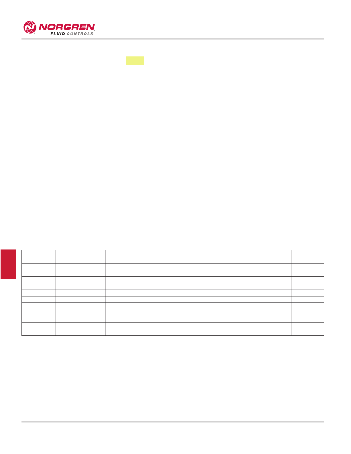
Number Housing Series Type Class
01 1 - Grommet 1, 2, 3, 6 Standard - dry tape wrapped with leads B**
01 2 - Conduit 1, 2, 3, 6 Standard - dry tape wrapped with leads B**
41 9 - Slotted 1 Free standing molded with leads B**
61 9 - Slotted 2, 3, Free standing molded with leads B**
61 3 - Yoke 2, 3 Free standing molded with leads B**
41 2 - Conduit 1, 2, 3 Potted with leads B**
31 9 - Slotted 2, 3 3/16" Vertical spade B**
51 9 - Slotted 2, 3 1/4" Vertical spade B**
51 3 - Yoke 2, 3 1/4" Top spade (Available with FWR option***) B**
41 1 - Grommet 6 Free standing molded with leads B**
41 2 - Conduit 6 Free standing molded with leads B**
51 9 - Slotted 6 1/4" Vertical spade B**
Page 2
7-7
KIP Numbering System
7
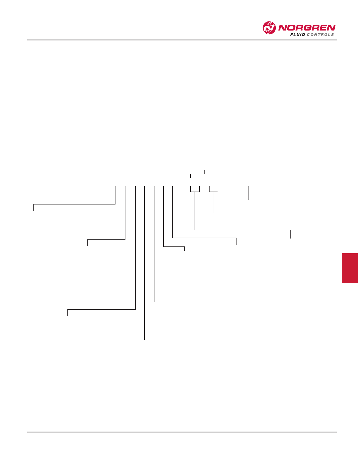
KIP Part Identification Numbering (PIN) System For Valves
The KIP part number provides information about every aspect of the product it represents. The first letter is an optional prefix which identifies
UL recognized, oxygen or low wattage. The following numbers identify series, ports, housing style, material, valve function, orifice, seal, coil
construction and coil temperature, in that order. The numerical value for each respective category represents one of multiple options. Where
possible, the organization of this KIP catalog presents information in the order of the part identification number. You may use the number as a
guide to finding information within the catalog.
The following chart is the key to understanding the KIP Part Identification Number.
PREFIXES
(Optional)
U = UL Recognized
Y = Oxygen Service
A = Low Wattage*
- 1.5 Watt
B = Low Wattage*
-2.0 Watt
C = Low Wattage*
-2.5 Watt
D = Low Wattage*
-3.0 Watt
G = Diaphragm
see page 21-23
for ordering
SERIES
1 = Series 1
2 = Series 2
3 = Series 3
6 = Series 6
PORT
3 = 1/8" NPT Male Bottom (a)
4 = 1/8" NPTF
5 = 1/4" NPTF (b)
6 = Manifold Mount (c)
7 = #10-32 UNF
8 = 3/8" NPT (f)
HOUSING
1 = Grommet
2 = 1/2" NPT Conduit
3 = Yoke (d)
4 = Yoke w/bracket (d)
7 = Grommet w/bracket
9 = Slotted (e)
0 = Slotted w/bracket (e)
BODY MATERIAL
0 = Stainless Steel
1 = Brass
3 = Operator
FUNCTION
1 = 2WNC
2 = 2WNO
3 = 3WNCFV
4 = 3WNCLC
5 = 3WNO
6 = 3WMP
7 = 3WDC (a)
ORIFICE
0 = 1/32"
1 = 3/64"
2 = 1/16"
3 = 5/64"
4 = 3/32"
5 = 1/8"
6 = 5/32"
7 = 3/16" (b)
8 = 1/4" (b)
9 = 3/8" (f)
COIL OPTIONS
See page 7-6
VOLTAGE
See page 7-6
SEAL
01 = Buna
02 = Fluorocarbon
®
03 = Neoprene
®
05 = Low temperature Buna
06 = Polyurethane (2WNC only)
08 = Teflon®(2WNC only)
12 = Neoprene W
®
13 = Ethylene Propylene (EPR
(Food Grade)
(a) = Available in Series 1, 2 & 3.
(b) = Available in Series 3 & 6.
(c) = Available in Series 1, 2 & 6.
(d) = Available in Series 2 & 3 only and must be used
with molded spade coil or free standing molded coil
with lead wires.
(e) = Slotted housing (used with 31 & 51 spade coil
option), available in Series 2, 3 & 6. Used with
molded coil 61 in Series 2 & 3, and 41 in Series 1.
(f) = Available in Series 6, 2WNC only.
(g) = Available in Series 1 & 2 diaphragm only.
U 2 4 0 1 1 5 - 0 2 5 1 - 24VDC
OPTIONAL
® Teflon and Neoprene are registered trademarks of E.I. Dupont De Nemours Co.
*Available in Series 1, 2 & 3 for 2-Way Normally Closed, 3-Way Normally Closed and 3-Way Multi-Purpose functions.
Page 3

7-26
KIP Series 1
7
www.norgren.com/fluid
Series 1
* Larger stop orifice available with reduced pressure ratings; consult KIP.
** Manifold Mount valve has maximum 400 MOPD rating for UL recognition.
Series 1
Orifice
Diameter
Cv Factor
MOPD
(psi)
Standard Valve Body
Grommet
Manifold Mount**
Valve Body-Grommet
LOW WATT Specifications
Cv Factor
1.5 WattA2.0 WattB2.5 WattC3.0 Watt
D
Body Stop Body Stop SS Brass SS Brass Body Stop
2-Way
Normally
Open
1/32 0.035 300 141020 141120 161020 161120
3/64 0.050 200 141021 141121 161021 161121
1/16* 0.095 150 141022 141122 161022 161122
2-Way
Nomally
Closed
1/32 0.035 800 141010 141110 161010 161110 0.030 125 300 500 775
3/64 0.050 500 141011 141111 161011 161111 0.050 30 100 175 300
1/16 0.095 300 141012 141112 161012 161112 0.085 - 30 65 95
5/64 0.135 200 141013 141113 161013 161113 0.125 - 15 40 65
3/32 0.175 175 141014 141114 161014 161114 0.170 - 10 25 40
1/8 0.245 100 141015 141115 161015 161115 0.225 - - - 4
5/32 0.290 50 141016 141116 161016 161116 0.280 - - - -
3-Way
Normally
Open
1/32 1/32 0.035 0.025 160 141050 141150 161050 161150
3/64 3/64 0.050 0.065 125 141051 141151 161051 161151
1/16 1/16* 0.085 0.115 100 141052 141152 161052 161152
5/64 1/16* 0.125 0.115 80 141053 141153 161053 161153
3/32 1/16* 0.165 0.115 60 141054 141154 161054 161154
1/8 1/16* 0.240 0.115 40 141055 141155 161055 161155
5/32 1/16* 0.285 0.115 10 141056 141156 N/A N/A
3-Way
Normally
Closed
(For free vent,
change
fifth digit
from 4 to 3)
1/32 1/32 0.035 0.025 200 141040 141140 161040 161140 0.030 0.025 100 - 150 -
3/64 3/64 0.050 0.065 150 141041 141141 161041 161141 0.050 0.060 - 80 120 -
1/16 1/16* 0.085 0.115 100 141042 141142 161042 161142 0.085 0.105 - 45 650 -
5/64 1/16* 0.125 0.115 80 141043 141143 161043 161143 0.120 0.105 - 25 - 50
3/32 1/16* 0.165 0.115 60 141044 141144 161044 161144 0.150 0.105 - - 20 35
1/8 1/16* 0.240 0.115 40 141045 141145 161045 161145 0.225 0.105 - - 10 20
5/32 1/16* 0.285 0.115 10 141046 141146 161046 161146 0.270 0.105 - 7 - 10
3-Way
Multi-
Purpose
1/32 1/32 0.035 0.025 150 141060 141160 161060 161160 0.030 0.025 - 80 - 95
3/64 3/64 0.050 0.065 100 141061 141161 161061 161161 0.050 0.060 - 25 40 60
1/16 1/16* 0.085 0.115 80 141062 141162 161062 161162 0.085 0.105 - - - 20
5/64 1/16* 0.125 0.115 60 141063 141163 161063 161163 0.120 0.105 - - - 8
3/32 1/16* 0.165 0.115 35 141064 141164 161064 161164 0.150 0.105 - - - -
1/8 1/16* 0.240 0.115 20 141065 141165 161065 161165 0.225 0.105 - - - -
5/32 1/16* 0.285 0.115 10 141066 141166 161066 161166 0.270 0.105 - - - -
3-Way
Directional
Control
1/32 1/32 0.035 0.025 230 141070 141170 161070 161170
3/64 3/64 0.050 0.065 160 141071 141171 161071 161171
1/16 1/16* 0.085 0.115 120 141072 141172 161072 161172
5/64 1/16* 0.125 0.115 80 141073 141173 161073 161173
3/32 1/16* 0.165 0.115 60 141074 141174 161074 161174
1/8 1/16* 0.240 0.115 35 141075 141175 161075 161175
5/32 1/16* 0.285 0.115 20 141076 141176 N/A 161176
Page 4

7-27
KIP Series 1
7
Series 1
Standard Valve
N
H
K
E
D
C
B
FR
A
M
G
D
C
B
FH
G
E
A
D
C
B
HP
FR
N
E
A
M
Hex Male
Valve Standard
Operator Standard
A B C D E F G H K M N R
Series
1
.99
(25)
.28
(7)
1.33
(33)
2.12
(54)
2.47
(63)
1.12
(29)
.64
(16)
32-
1/2°
.73
(19)
1/8-27
NPTF
#8-32 UNC
x 1/4 MFT
1/8-27
NPTF
A B C D E F G H
Series
1
1.02
(26)
.52
(13)
1.32
(34)
1.67
(42)
.64
(16)
1.12
(29)
3/4-32
UNEF
1/8-27
NPTF
A B C D E F H M N P R
Series
1
.94(24)
Hex
.27
(7)
2.12
(54)
2.47
(63)
.64
(16)
1.12
(29)
1.32
(33)
1/8-27
NPTF
1/8-27 NPTF .44 (11)
1/8-27
NPTF
1/4-18 NPTF .56 (14)
Bracket Dimensions
Mounting Brackets
E
F
A
D
C
B
A B C D E F
Series 1
2.13 (54) 1.33 (34) .20 (5) 2.63 (67) 1.45 (37) 1.93 (49)
Manifold Mount Valve
Manifold Mount Interface
D
C
N
B
FR
M
E
A
A B Max
R
40
A B C D E F m n r
Series
1
.99
(25)
1.07
(27)
1.87
(48)
2.22
(56)
.64
(16)
1.12
(29)
5/16 24
UNF
.25
(6)
1/8-27 NPTF
A B R
Series 1 & 2
5/16 - 24 UNF-2B x .26 MFT .09 (2) .31 (8)
NOTE: A is underseat connection** B is overseat connection***
 Loading...