

Page 1
Conform to BS EN 837-1:1998
Back or bottom connecton
Panel mount, stainless steel and Underwriters
Laboratories Inc. listed gauges available
Wide pressure and temperature and range
Technical features
Medium:
Compressed air, oil and
gases or liquids which do
not corrode copper alloys
Port connections:
White face scale
M5, R1/8, G1/8A, G1/4A
Ø 6,5 mm (for model 9273... only)
Black face scale
1/8 NPT, 1/4 NPT, Ø 5/32
(for North America)
Accuracy:
2,5% of full scale
Ambient/Media temperature:
-40 ... +65°C (-40 ... +150°F)
For model 9273... only:
-20 ... +52°C (-4 ... +125°F)
Air supply must be dry enough
to avoid ice formation at
temperatures below +2°C (+35°F)
18-013-..., V70534-..., 9273...
Materials
Body: ABS, steel or stainless steel
Lens: steel or plastic bodies
have plastic lens; stainless steel
bodies has glass lens
Connectors: steel or plastic
bodies have brass connector;
stainless steel bodies has
stainless steel connector
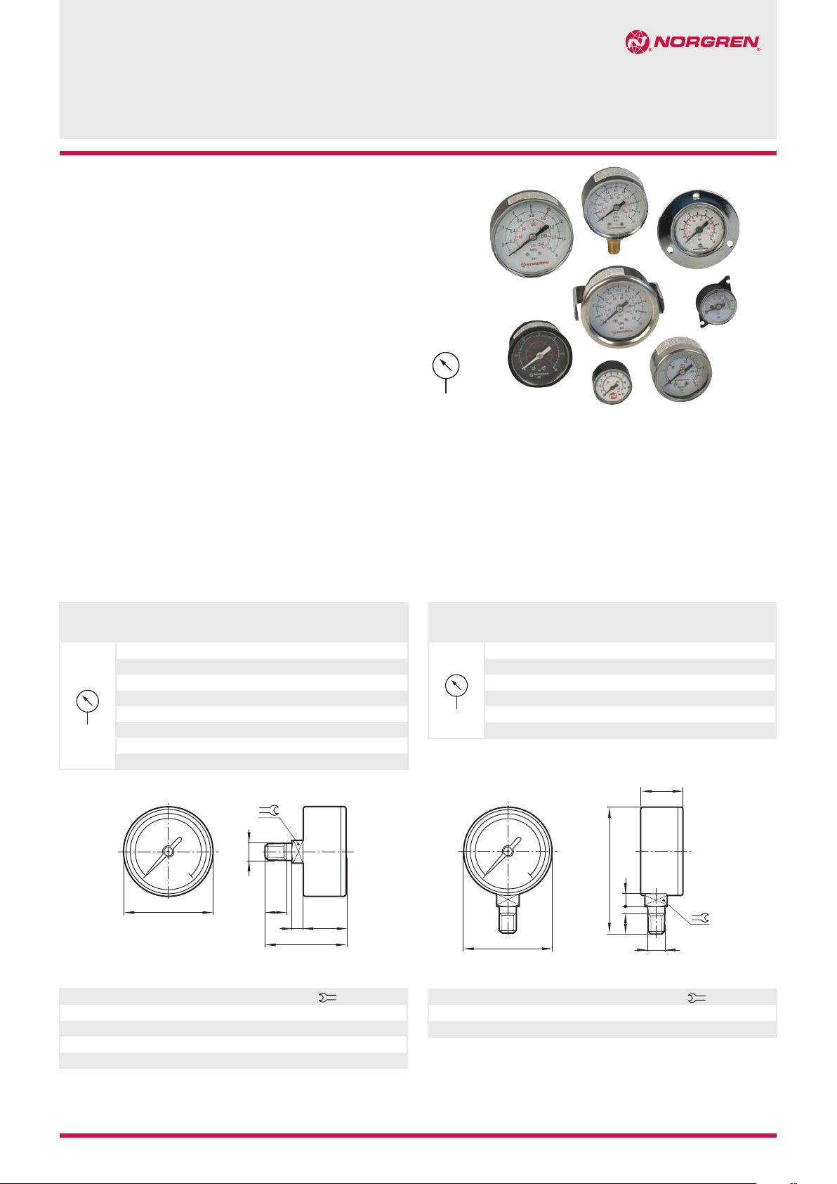
Pressure gauges
M5, 1/8” & 1/4”, Ø 4 mm
For model 9273... only:
Body: PA 66
Lens: Polycarbonate
‘O’ ring: NBR
Center back connection, white face
Symbol Scale range
bar *1) Mpa psi
0 ... 1 — 0 ... 14 — 18-013-887 — 18-013-893
0 ... 1,6 0 ... 0,16 0 ... 23 — 18-013-991 18-013-010 —
0 ... 2,5 — 0 ... 36 — 18-013-886 — 18-013-892
0 ... 4 0 ... 0,4 0 ... 58 — 18-013-990 18-013-011 —
0 ... 6 0 ... 0,6 0 ... 87 — 18-013-885 18-013-012 18-013-891
0 ... 10 0 ... 1 0 ... 145 V70534-500 *2) 18-013-989 18-013-013 18-013-890
0 ... 16 0 ... 1,6 0 ... 232 — 18-013-884 — 18-013-889
0 ... 25 0 ... 2,5 0 ... 362 — 18-013-908 18-013-014 18-013-888
*1) primary scale
*2) bar and psi scale only
A
Model – Diameter & Connection
Ø 25 Ø 40 Ø 50 Ø 63
M5 R1/8 R1/8 R1/8
B
Bottom connection, white face
Symbol Scale range
bar *1) Mpa psi
0 ... 1,6 0 ... 0,16 0 ... 23 18-013-024 —
0 ... 4 0 ... 0,4 0 ... 58 18-013-025 —
0 ... 6 0 ... 0,6 0 ... 87 18-013-026 —
0 ... 10 0 ... 1 0 ... 145 18-013-027 18-013-854
0 ... 16 0 ... 1,6 0 ... 232 — 18-013-853
0 ... 25 0 ... 2,5 0 ... 362 18-013-028 —
*1) primary scale
C
G
FE
C
A
Model – Diameter & Connection
Ø 50 Ø 63
R1/8 G1/4
F
G E
B
Ø A B C E F G Weight (g)
25 M5 28 3,5 16,5 6 12 10
40 R1/8 45 9 26 10 14 49
50 R1/8 50 9 26 14 14 51
63 R1/8 48 6,5 27,5 10 14 90
7/14 2000-8192c
Our policy is one of continued research and development. We therefore reserve the right to amend,
without notice, the specifications given in this document. © 2014 Norgren Americas
Ø A B C E F G Weight (g)
50 R1/8 69 6 28 12,5 14 72
63 R1/4 83 6 28 15 14 104
N/en 8.900.900.01
Page 2
18-013-..., V70534-..., 9273...
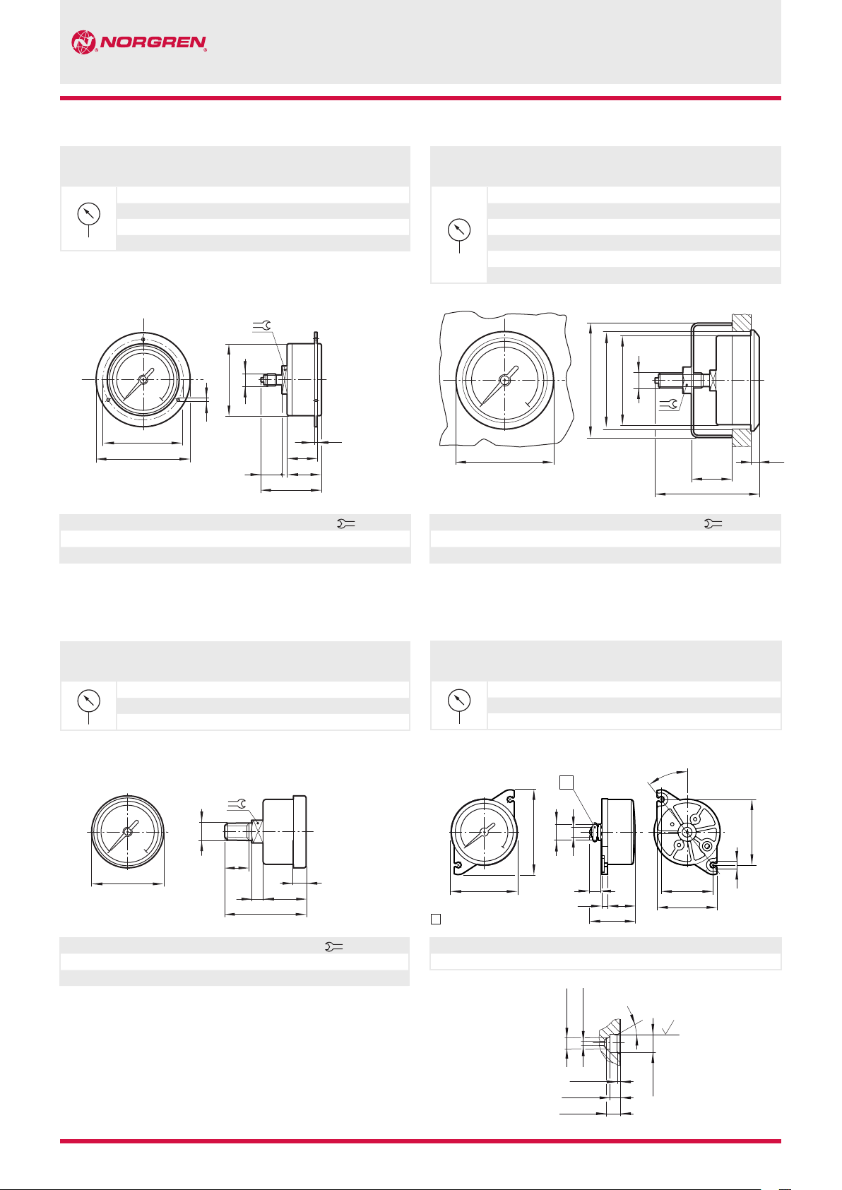
Center back connection, panel mount, white face
(secured from front with screws)
Symbol Scale range
bar *1) Mpa psi
0 ... 1,6 0 ... 0,16 0 ... 23 18-013-879 18-013-883
0 ... 6 0 ... 0,6 0 ... 87 18-013-878 18-013-882
0 ... 10 0 ... 1 0 ... 145 18-013-877 18-013-881
0 ... 16 0 ... 1,6 0 ... 232 — 18-013-880
*1) primary scale
A
D
K
L
Ø A B C Ø D F G Ø K Ø L P R Weight (g)
42 G1/8A 42,5 3,6 25 12 53,5 60,5 23 1 11 81
63 G1/4A 46,5 3,6 29 16 75 85 26 2 14 79
Model - Diameter & Connection
Ø 40 Ø 63
G1/8A G1/4A
B
R
P
F
G
C
Center back connection, panel mount, white face
(secured from rear with clamping bar)
Symbol Scale range
bar *1) Mpa psi
0 ... 1,6 0 ... 0,16 0 ... 23 18-013-996 —
0 ... 4 0 ... 0,4 0 ... 58 18-013-995 —
0 ... 6 0 ... 0,6 0 ... 87 18-013-994 —
0 ... 10 0 ... 1 0 ... 145 18-013-993 18-013-852
0 ... 16 0 ... 1,6 0 ... 232 — 18-013-851
0 ... 25 0 ... 2,5 0 ... 362 18-013-992 —
*1) primary scale
ø K
ø L
A
Ø A B C Ø J Ø K Ø L M P Weight (g)
50 G1/8A 62 48 52 66 0 ... 4,5 30 17 110
63 G1/4A 62 62 65 74 0 ... 4,5 37 17 140
Model - Diameter & Connection
Ø 50 Ø 63
G1/8A G1/4A
B
ø J
P
C
M
Stainless steel gauges
Center back connection, white face
Symbol Scale range
bar *1) Mpa lbf/m
0 ... 6 — 0 ... 87 — 18-013-913
0 ... 10 — 0 ... 145 18-013-844 18-013-909
0 ... 25 — 0 ... 362 — 18-013-905
*1) primary scale
B
G
A
Ø A B C E F G M Weight (g)
40 1/8 PTF 36 6,5 22 6
40 1/4 PTF 46,5 7,5 25 11
Model - Diameter & Connection
Ø 40
2
1/8 PTF 1/4 PTF
M
FE
C
12 58
9
14 74
9
Gauge kit
Center back connection, white face
Symbol Scale range
bar Mpa psi
0 ... 12 *1) — 0 ... 175 9273KIT-01
0 ... 12 0 ... 1,2 *1) — 9273KIT-02
*1) primary scale
*2) part number = pack of 5 gauges, ‘O’ rings and screw driver
1
P
B
R
A
1
‘O’ ring
Ø A B
+0,2 C E F G H +0,2 M N O P R +0,2 Weight (g)
26 6,3 17,5 2,3 10,5 4,7 2,2 20,4 23,5 25,8 33,4 3,8 7
G
F
E
C
Model – Diameter *2)
Ø 26
38,3°
M
N
Interface
4,25 + 0,3
1,68 + 0,17
30°
N7
O
H
N/en 8.900.900.02
1,45 +0,2
3,55 + 0,2
4,85 + 0,3
Our policy is one of continued research and development. We therefore reserve the right to amend,
without notice, the specifications given in this document. © 2014 Norgren Americas
6,75 + 0,2
2000-8192c 7/14
Page 3

18-013-..., V70534-..., 9273...
Center back connection, black face
(for North America)
Symbol Scale range
psig *1) bar
Mpa
0 ... 30 0 ... 2 0 ... 0.2 18-013-214 18-013-201 18-013-207
0 ... 60 0 ... 4 0 ... 0.4 18-013-211 18-013-202 18-013-208
0 ... 100 0 ... 7 0 ... 0.7
0 ... 160 0 ... 11 0 ... 1.1 18-013-212 18-013-204 18-013-209
0 ... 300 0 ... 20 0 ... 2.1 18-013-275 18-013-205 18-013-210
0 ... 400 0 ... 28 0 ... 2.8
*1) primary scale
Dimensions in inches (mm)
Model - Diameter & Connection
Ø 1.5” (Ø 40 mm) Ø 2” (Ø 50 mm) Ø 2” (Ø 50 mm)
1/8 NPT 1/8 NPT 1/4 NPT
–
–
18-013-203 18-013-235
18-013-206
–
B
Bottom back connection, black face
(for North America)
Symbol Scale range
psig *1) bar Mpa *4)
0 ... 15 0 ... 1
0 ... 30 0 ... 2 0 ... 0.2 18-013-224 18-013-030 *2)
0 ... 60 0 ... 4 0 ... 0.4 18-013-225 18-013-083 *2)
0 ... 100 0 ... 7 0 ... 0.7 18-013-265 18-013-084 *2)
0 ... 160 0 ... 11 0 ... 1.1 18-013-273 18-013-085 *2)
0 ... 300 0 ... 20
0 ... 2000 0 ... 135
0 ... 3000 0 ... 205
*1) primary scale
*2) Underwriters Laboratories Inc. listed
*3) Shipped with pulsation dampener installed. Please add -9D
to the end of model number
*4) Mpa scale for Ø 1.5” only
Dimensions in inches (mm)
– –
– –
– –
– –
Model - Diameter & Connection
Ø 1.5” (Ø 40 mm) Ø 2” (Ø 50 mm)
1/8 NPT 1/4 NPT
Projection/Third angleProjection/Third angle
F
C
18-013-082
18-013-086 *2)
18-013-244 *3)
18-013-087 *3)
A
Ø A B C E F (G) Weight (lb)
1.5 (40) 1/8 NPT 1.60 (41) 0.97 (25) 0.23 (6) 0.40 (10) 0.43 (11) 0.12 (54 g)
2 (50) 1/8 NPT 1.73 (44) 1.03 (26) 0.23 (6) 0.47 (12) 0.55 (14) 0.17 (77 g)
2 (50) 1/4 NPT 1.73 (44) 1.03 (26) 0.23 (6) 0.47 (12) 0.55 (14) 0.18 (81 g)
(G)
FE
C
E
G
A
Ø A B C E F G Weight (lb)
1.5 (40) 1/8 NPT 2.2 (56) 0.31 (8) 0.90 (23) 1.11 (28) 0.43 (11) 0.14 (64 g)
2 (50) 1/4 NPT 2.7 (69) 0.31 (8) 1.06 (27) 1.42 (36) 0.55 (14) 0.22 (100 g)
B
7/14 2000-8192c N/en 8.900.900.03
Our policy is one of continued research and development. We therefore reserve the right to amend,
without notice, the specifications given in this document. © 2014 Norgren Americas
Page 4

18-013-..., V70534-..., 9273...
Center back connection, panel mounted, black face
(for North America)
Symbol Scale range
psig *1) bar Mpa
0 ... 30 0 ... 2 0 ... 0.2 5PG-306-000
0 ... 60 0 ... 4 0 ... 0.4 5PG-312-000
0 ... 100 0 ... 7 0 ... 0.7 5PG-320-000
*1) primary scale
Dimensions in inches (mm) Dimensions in inches (mm)
A
Model - Diameter & Connection
Ø 1.5” (Ø 40 mm)
1/8 NPT außen & 10 ... 32 innen
B
ø J
ø K
GM
P
C
ø L
Center back connection, panel mounted, black face
(for North America)
Symbol Scale range
psig *1) bar Mpa
0 ... 100 0 ... 7 0 ... 0.7 18-013-538
*1) primary scale
A
Model
Ø 1.5” (Ø 40 mm)
Ø 5/32” PIF (Ø 4 mm)
M
P
C
Projection/Third angleProjection/Third angle
B
ø J
ø L
ø K
Ø A B C G Ø J Ø K
1.5 (40) 1/8 NPT 1.69 (43) 0.60 (15) 1.61 (41) 1.63 (41)
Ø L M P Weight (lb)
2.1 (53) 0.18 (4,5) 1.04 (27) 0.55 (14) 0.15 (68 g)
Ø A Ø B C Ø J Ø K
1,5 (40) 0.156 (4) 1.71 (43) 1.61 (41) 1.63 (41)
Ø L M P Weight (lb)
2.1 (53) 0.18 (5) 0.86 (22) 0.55 (14) 0.15 (68 g)
Warning
These products are intended for use in industrial compressed air and
fluid systems only. Do not use these products where values can
exceed those listed under »Technical features/data«.
Before using these products with other than those specified, for nonindustrial applications, life-support systems, or other applications
not within published specifications, consult NORGREN.
Through misuse, age, or malfunction, components used in
fluid power systems can fail in various modes.
N/en 8.900.900.04
Our policy is one of continued research and development. We therefore reserve the right to amend,
without notice, the specifications given in this document. © 2014 Norgren Americas
The system designer is warned to consider the failure modes of all
component parts used in fluid power systems and to provide adequate
safeguards to prevent personal injury or damage to equipment in the
event of such failure.
System designers must provide a warning to end users in the system
instructional manual if protection against a failure mode cannot be
adequately provided.
System designers and end users are cautioned to review specific
warnings found in instruction sheets packed and shipped with
these products.
2000-8192c 7/14
 Loading...