

Page 1

Littleton, CO USA Phone 303-794-2611 Fax 303-795-9487
FIT-3-1
Function Fittings,
Flow Controls, and
Accessory Valves
Section 3
12 VA0 Right Angle (Banjo) Flow Control (inch-knob adj.) . .FIT-3-3
12 VB0 Right Angle (Banjo) Flow Control (inch-slot adj.) . . .FIT-3-3
10 TA0 Right Angle (Banjo) Flow Control (metric-knob adj.) FIT-3-4
10 K51 Right Angle (Banjo) Flow Control (metric-slot adj.) . .FIT-3-4
T1000 In-line Flow Control (NPT and ISO G) . . . . . . . . . . . . . .FIT-3-6
T15 Push-In Flow Regulators . . . . . . . . . . . . . . . . . . . . . . . . . .FIT-3-8
M/800, C/800 Heavy Duty In-Line Flow Control . . . . . . . . . . . .FIT-3-10
M/600, C/600 Heavy Duty In-Line Flow Control . . . . . . . . . . . .FIT-3-12
M/650, C/650, M/677, C/677 Precision Flow Controls . . . . . . .FIT-3-14
T51/T52/T53 Series, PIF Non Return Valves . . . . . . . . . . . . . .FIT-3-16
T55, T56 Non-Return Valves . . . . . . . . . . . . . . . . . . . . . . . . . . .FIT-3-16
T60 Air Fuse (Excess Flow Check) (NPT and ISO G) . . . . . . .FIT-3-18
Pressure Reducing Fitting (inch and metric) . . . . . . . . . . . . . .FIT-3-23
Pilot Operated Check Valve (inch and metric) . . . . . . . . . . . .FIT-3-26
T70 Quick Exhaust Valves (NPT and ISO G) . . . . . . . . . . . . . .FIT-3-28
T65 1/8" and 1/4" Shuttle Valves (NPT and ISO G) . . . . . . . . .FIT-3-30
Page 2
FIT-3-2
Littleton, CO USA Phone 303-794-2611 Fax 303-795-9487
Function Fittings and Flow Controls
● 360° rotation of the banjo body around the bolt allows for ideal
positioning of tubing.
● Low profile and reduced physical size provide space saving
installations, while internal configuration provides the flow
capacity of much bulkier designs.
● Tapered adjustment needles with large adjustment ranges
provide linear flows and greater precision.
● Knurled adjustment knobs (w/screw driver slot) and lock nuts on
12 VA0 and 10 TA0 series provide finger tip adjustment. Tamper
resistance on the 12 VBO and 10 K51 is provided by a slotted
adjustment screw covered by a protective plastic cap.
● Direct mounting of flow controls on pneumatic actuators
minimizes the adjustment problems encountered due to the
compressibility of air in long tubing runs between the actuator
and control valving. Additionally, direct mounted flow controls
end the confusion over which actuator in a circuit is being
controlled.
● Metallic components are limited to nickel plated all brass
construction, eliminating the potential problems encountered
with products constructed of dissimilar metals.
● Adjustment needles and banjo bodies are retained, preventing
accidental loss of the needle or lock nut.
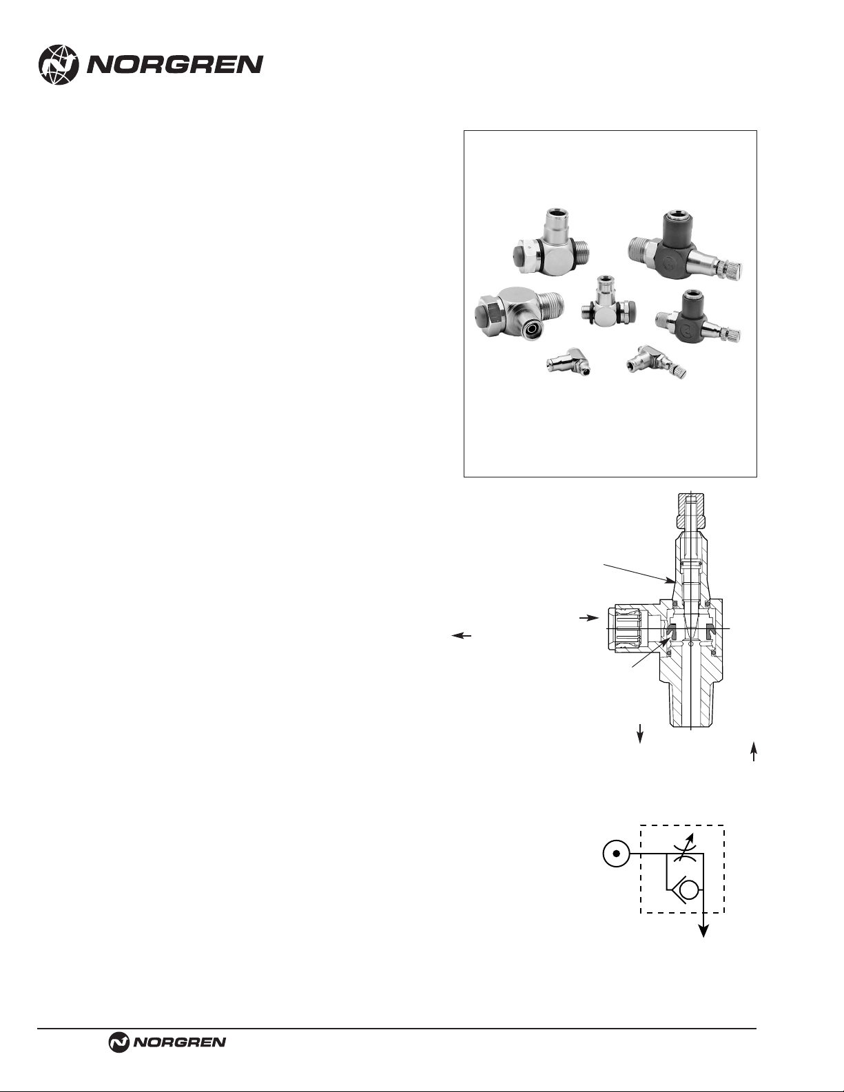
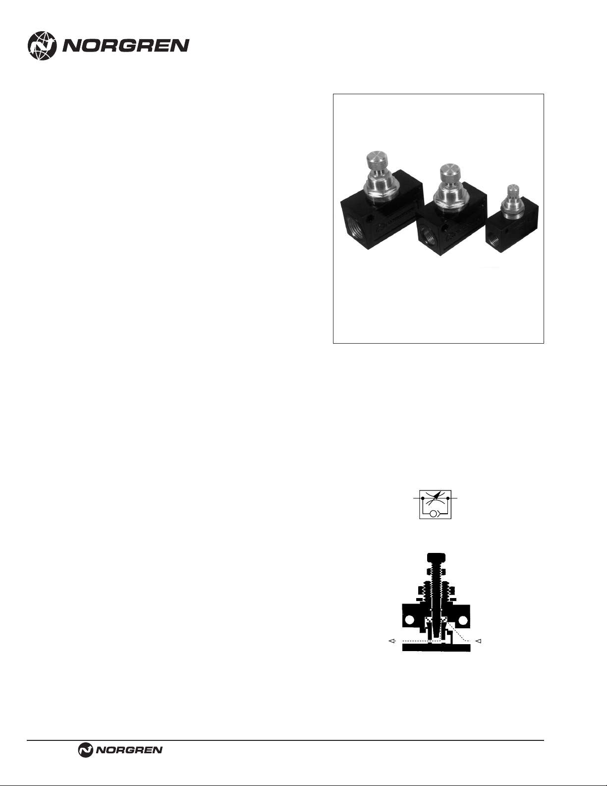
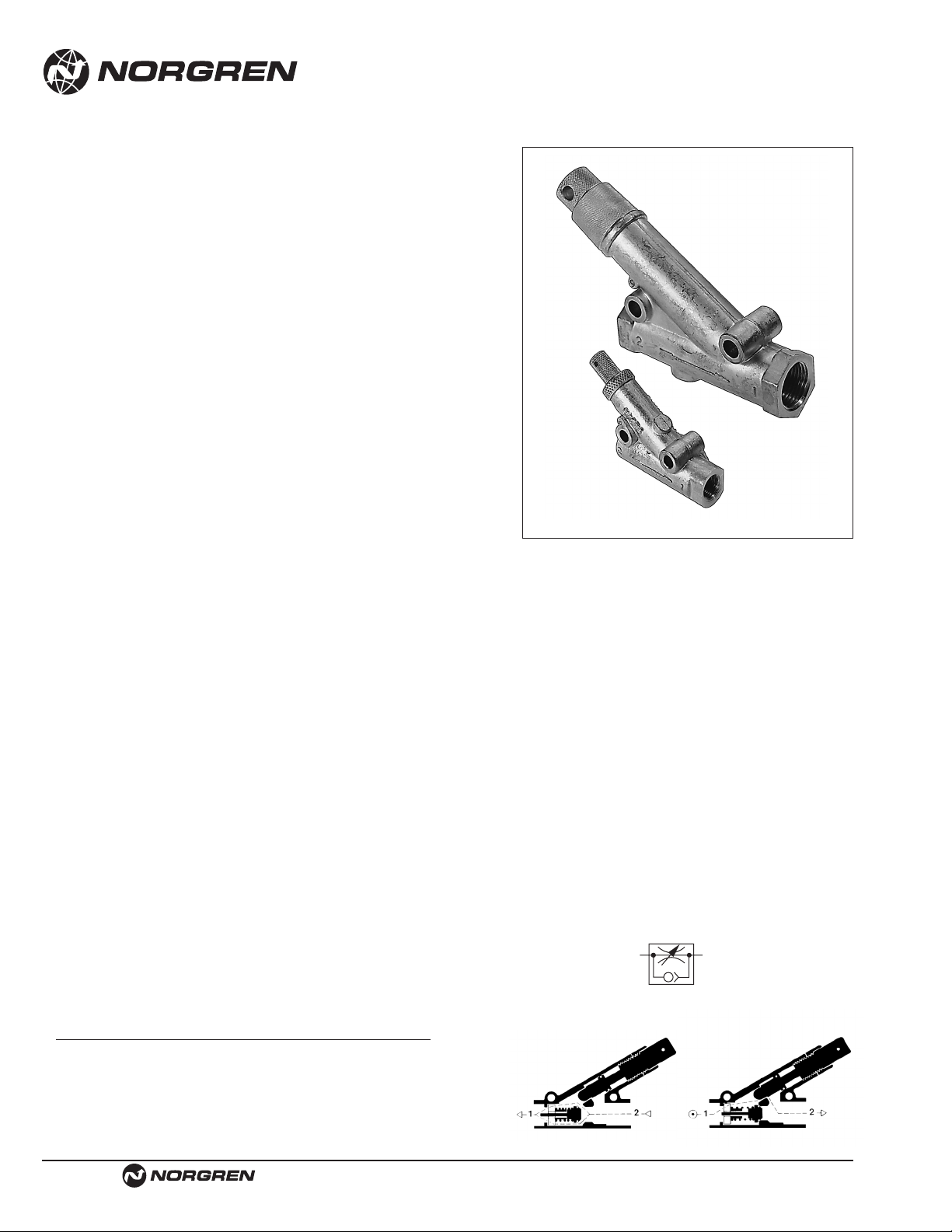
Right Angle (Banjo) Flow Controls
Operation:
Flow Controls are checked adjustable controls of the meter out type.
Compressed air passes freely into the push-in fitting portion of the flow
control, flowing past the check seal and entering the connected
component. In reverse flow conditions, air passes back into the flow
control and energizes the check seal. Air must now flow through the
metered passage controlled by the tapered adjustment needle of the flow
control, and finally exits through the push-in fitting end.
Specifications
Fluid: Compressed air.
Note:
For other types of fluids or compressed gases, please
consult factory.
Working Pressure: 5 to 150 psig (.3 to 10 bar)
Temperature Range: 0° to 175°F (-20° to 80°C)
Materials of Construction:
Banjo bolt, collet, adjustment knob and lock nut: Nickel plated brass
Tapered adjusting needle: Brass
Banjo Body, 12 VA0 XXXX and 10 TA0: Thermoplastic
12 VBO and 10 K51 XXXX: Nickel plated brass
O-rings and check-seal: Silicone free Nitrile
Sealing washer: Thermoplastic (ISO G and 10-32 UNF)
Tubing: Nylon 11 or 12, 95 durometer polyurethane.
Thread Sealant: Thread sealant is applied to the full circumference of
tapered male threads.
Options
Special versions of the flow controls are available, including meter-in
(12 WA0 Series) and bi-directional control configurations.
Please
consult factory with specific quantities and requirements.
Free Flow In
(Metered Flow Out)
Free Flow Out
(Metered Flow In)
Tapered Adjustment
Needle
Check Seal
PneumaticSymbol
Page 3
Detroit, MI USA Phone 800-394-6804 Fax 734-591-1818
FIT-3-3
Function Fittings and Flow Controls
B
A NPT or
Tube UNF KL
O.D. Thread Part Number C D E F G H J A/F Adj
10-32 UNF 12 VA0 0210
0.37 1.04 0.16 0.74 0.38 1.51 0.45
–
0.12
5/32"
(9.5) (26.5) (4.0) (18.7) (9.5) (38.4) (11.4) (3.0)
1/8 12 VA0 0218
0.45 0.87 0.31 0.35 0.63 2.09 0.89
9/16"
0.12
(11.5) (22.0) (8.0) (9.0) (16.0) (53.0) (22.5) (3.0)
1/8 12 VA0 0418
0.51 0.91 0.31 0.35 0.63 2.09 0.89
9/16"
0.12
1/4"
(13.0) (23.0) (8.0) (9.0) (16.0) (53.0) (22.5) (3.0)
1/4 12 VA0 0428
0.53 1.00 0.39 0.43 0.79 2.64 1.16
11/16"
0.24
(13.5) (25.5) (10.0) (11.0) (20.0) (67.0) (29.5) (6.0)
1/4 12 VA0 0628
0.77 1.24 0.39 0.43 0.79 2.64 1.16
11/16"
0.24
3/8"
(19.5) (31.5) (10.0) (11.0) (20.0) (67.0) (29.5) (6.0)
3/8 12 VA0 0638
0.77 1.28 0.47 0.51 0.87 3.07 1.30
3/4"
0.24
(19.5) (32.5) (12.0) (13.0) (22.0) (78.0) (33.0) (6.0)
1/2" 1/2" 12 VA0 0748
0.91 1.50 0.63 0.71 1.06 3.66 1.65
7/8"
0.28
(23.0) (38.0) (16.0) (18.0) (27.0) (93.0) (42.0) (7.0)
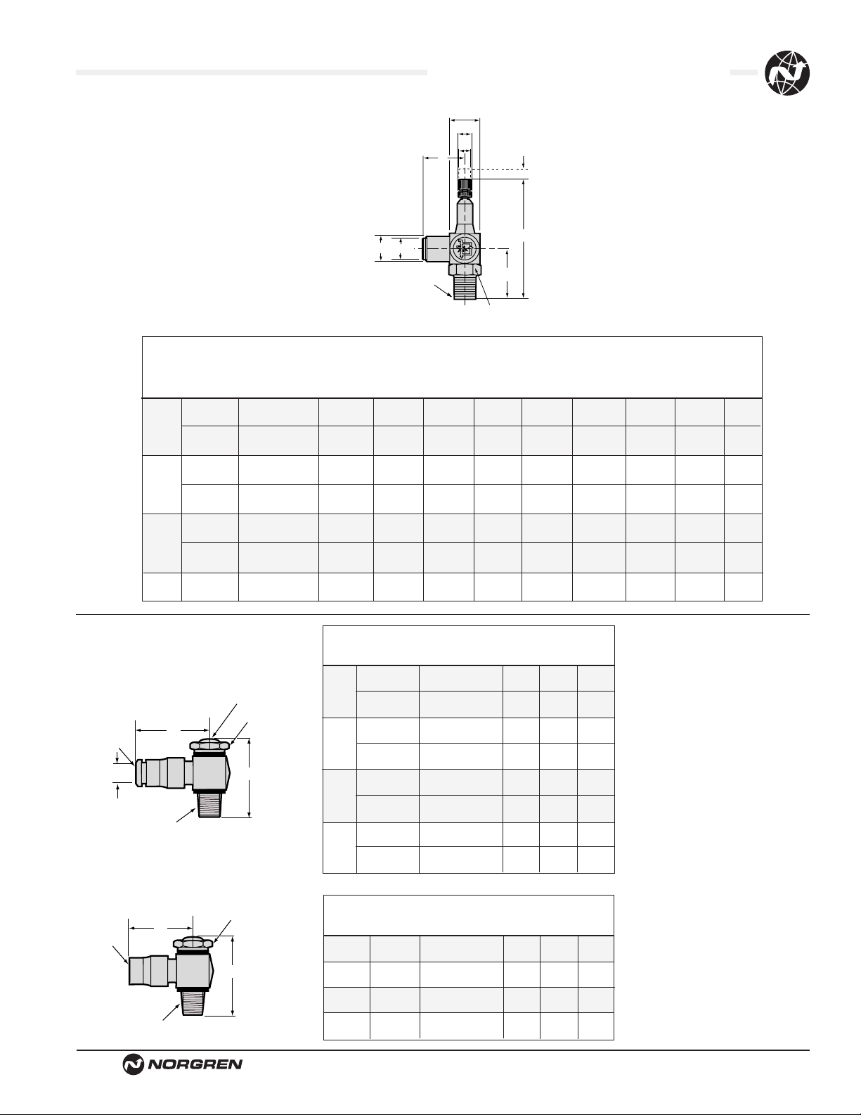
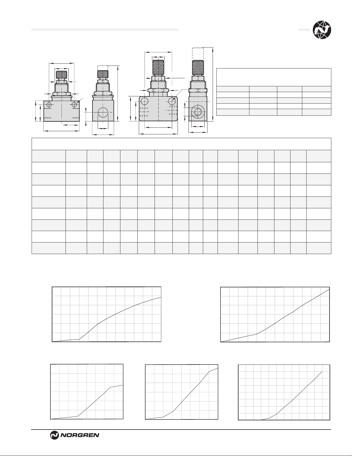
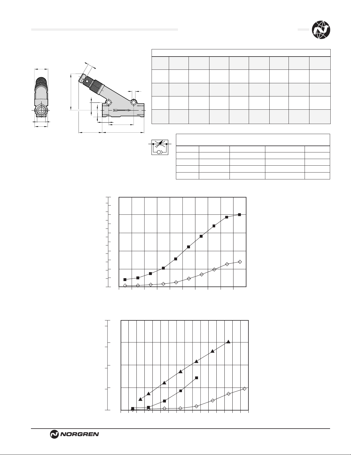
VA0 Series
Dimensions in Inches (mm)
A B NPT
Tube or UNF F
O.D. Thread Part Number C A/F G
10-32 UNF 12 VB0 0210
0.74
-
1.06
5/32"
(19) (27)
1/8 12 VB0 0218
0.88
9/16"
1.57
(22) (40)
1/8 12 VB0 0418
0.91
9/16"
1.57
1/4"
(23) (40)
1/4 12 VB0 0428
0.99
3/4"
1.83
(25) (46)
1/4 12 VB0 0628
1.23
3/4"
1.83
3/8"
(31) (46)
3/8 12 VB0 0638
1.29
7/8"
2.22
(33) (56)
3/8 12 VB0 0738
1.46
7/8"
2.22
1/2"
(37) (56)
1/2 12 VB0 0748
1.56
11/16"
2.55
(40) (65)
VB0 Series
Dimensions in Inches (mm)
AB
NPT NPT
Female Male Part Number C F G
1/8 1/8 12 VB0 1818
0.83
9/16"
1.57
(21) (40)
1/4 1/4 12 VB0 2828
1.14
3/4"
1.83
(29) (46)
3/8 3/8 12 VB0 3838
1.24
7/8"
2.22
(31) (56)
1/2 1/2 12 VB0 4848
1.53
11/16"
2.55
(39) (65)
G Square
Ø F
ØE
D
L
Adjustment
ØA
ØC
B
H (Closed)
J
‘K’ A/F Hex
Protective cap
covering adjustment
C
A
ØA
B
C
A
B
F
A/F
G
F
A/F
G
Page 4
FIT-3-4
Detroit, MI USA Phone 800-394-6804 Fax 734-591-1818
Function Fittings and Flow Controls
B
A ISO G or
Tube Metric C
O.D. Thread Part Number A/F D E G L S
M5 X .8 10 K51 0405
8 9.5 26.5 4.0 18.7 2.5
(.31) (.37) (1.04) (.16) (.74) (.10)
4
1/8 10 K51 0418
14 11.0 34.0 6.5 20.6 5.0
(.55) (.43) (1.34) (.26) (.81) (.20)
M5 X .8 10 K51 0505
8 11.0 26.5 4.0 20.2 2.5
5
(.31) (.43) (1.04) (.16) (.80) (.10)
1/8 10 K51 0518
14 11.5 34.0 6.5 21.7 5.0
(.55) (.45) (1.34) (.26) (.85) (.20)
M5 X .8 10 K51 0605
8 12.5 26.5 4.0 22.2 2.5
(.31) (.49) (1.04) (.16) (.87) (.10)
6 1/8 10 K51 0618
14 12.5 34.0 6.5 23.7 5.0
(.55) (.49) (.1.34) (.26) (.93) (20)
1/4 10 K51 0628
17 13.0 36.5 7.0 24.2 8.5
(.67) (.51) (1.44) (.28) (.95) (.33)
1/8 10 K51 0818
14 13.5 34.0 6.0 23.7
–
(.55) (.53) (1.34) (.26) (.93)
1/4 10 K51 0828
17 14.0 36.5 7.0 24.7 8.5
8
(.67) (.55) (1.44) (.28) (.97) (.33)
3/8 10 K51 0838
22 16.5 51.5 10.0 26.7 10.0
(.87) (.65) (2.03) (.39) (1.05) (.39)
10 3/8 10 K51 1038
22 17.0 51.5 10.0 31.2 10.0
(.87) (.67) (2.03) (.39) (1.23) (.39)
12 1/2 10 K51 1248
27 17.5 57.5 10.0 38.2
–
(1.06) (.69) (2.26) (.39) (1.50)
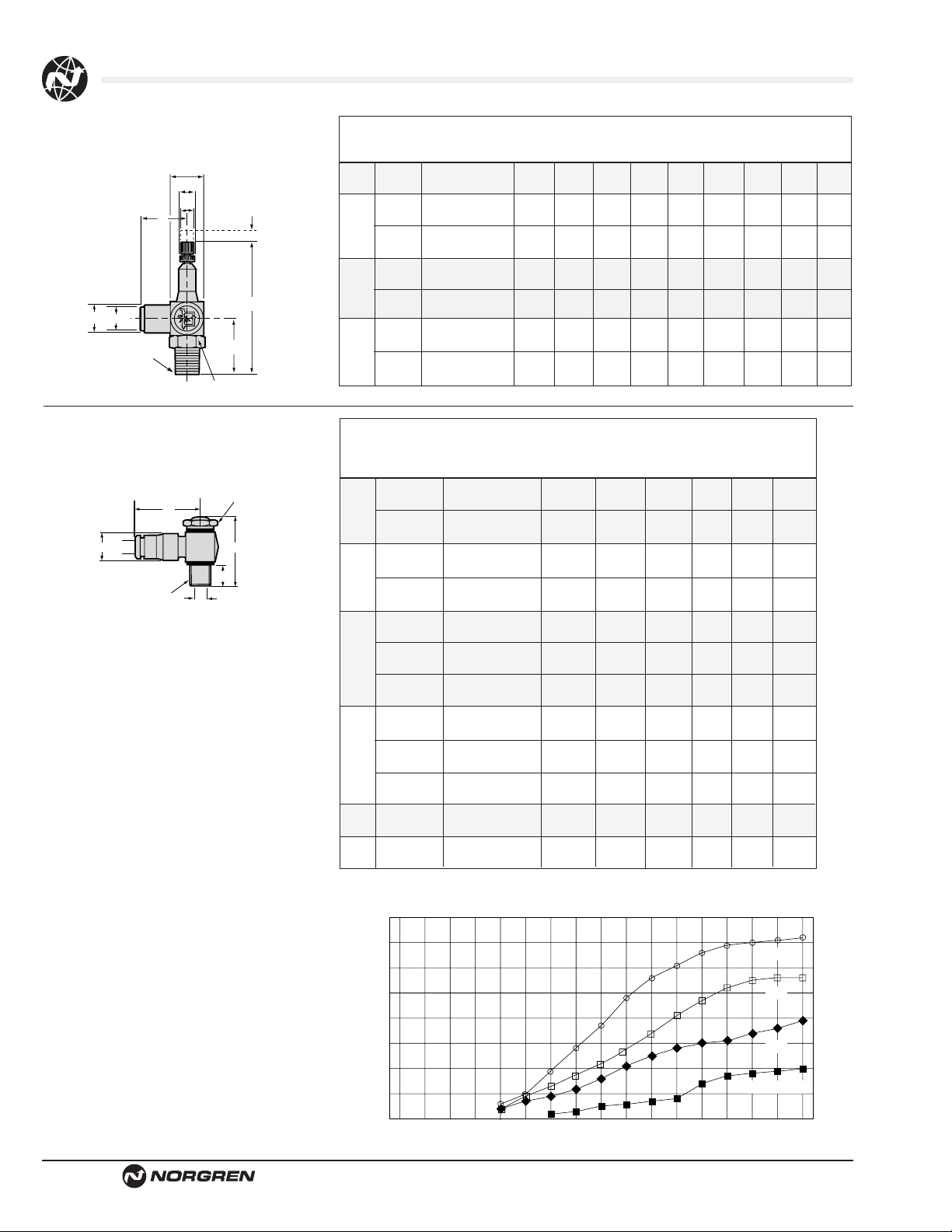
K51 Series
Dimensions in Inches (mm)
AB
Tube ISO R K L
O.D. Thread Part Number C D E F G H J A/F Adj
4 1/8 10 TA0 0418
11.5 22.0 8.0 9.0 16 53 22.5 14 3
(.45) (.87) (.31) (.35) (.63) (2.09) (.89) (.55) (.12)
1/8 10 TA0 0618
13.0 23.0 8.0 9.0 16 53 22.5 14 3
(.51) (.91) (.31) (.35) (.63) (2.09) (.89) (.55) (.12)
6
1/4 10 TA0 0628
13.5 25.5 10.0 11.0 20 67 29.5 17 6
(.53) (1.00) (.39) (.43) (.79) (2.64) (1.16) (.67) (.24)
1/4 10 TA0 0828
15.5 27.0 10.0 11.0 20 67 29.5 17 6
8
(.61) (1.06) (.39) (.43) (.79) (2.64) (1.16) (.67) (.24)
3/8 10 TA0 0838
15.5 28.0 12.0 13.0 22 78 33.0 19 6
(.61) (1.10) (.47) (.51) (.87) (3.07) (1.30) (.75) (.24)
1/4 10 TA0 1028
19.5 31.5 10.0 11.0 20 67 29.5 17 6
(.77) (1.24) (.39) (.43) (.79) (2.64) (1.16) (.67) (.24)
10
3/8 10 TA0 1038
19.5 32.5 12.0 13.0 22 78 33.0 19 6
(.77) (1.28) (.47) (.51) (.87) (3.07) (1.30) (.75) (.24)
G Square
D
Ø F
ØE
J
‘K’ A/F Hex
B
H (Closed)
L
Adjustment
ØC
ØA
TA0 Series
Dimensions in MM (inches)
L
ØD
ØA
B
G
ØS
C
A/F
E
Air Flow
(I/s)
(8)
(7)
(6)
(5)
(4)
(3)
(2)
(1)
scfm
17.0
14.8
12.7
10.0
8.0
6.4
4.2
2.0
0
012345678
Inlet pressure 90 psig (6 bar), flow to atmosphere
12 VA0 and 10 TA0 BANJO FLOW CONTROL
FLOW CHARACTERISTICS
Number of Turns
3/8
1/4
1/8
10-32 UNF/M5
Page 5
Detroit, MI USA Phone 800-394-6804 Fax 734-591-1818
FIT-3-5
Function Fittings and Flow Controls
Air Flow
(I/s)
(40)
(30)
(20)
(10)
Air Flow
(l/s)
(11)
(10)
(9)
(8)
(7)
(6)
(5)
(4)
(3)
(2)
(1)
scfm
84.8
63.6
42.0
21.0
0
01234567891011
Inlet pressure 90 psig (6 bar), flow to atmoshpere
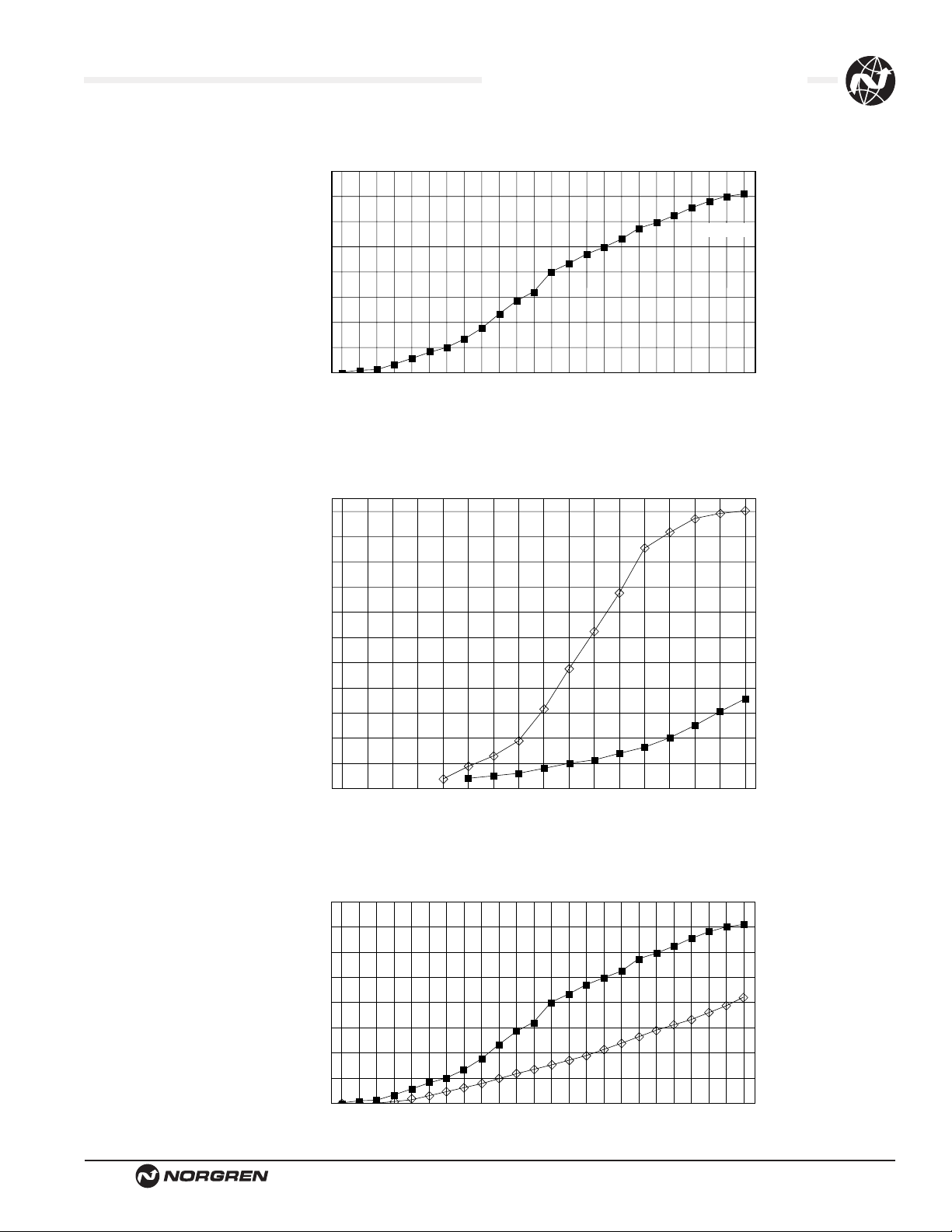
FLOW CHARACTERISTICS
1/2 NPTF
Number of Turns
12 VB0 and 10 K51 BANJO FLOW CONTROL
FLOW CHARACTERISTICS
scfm
23.0
21.0
19.0
17.0
14.8
12.7
10.6
8.5
6.4
4.2
2.1
0
012345678
12 VAO Banjo Flow Control Flow
Inlet pressure 90 psig (6 bar), flow to atmosphere
Number of Turns
1/4
1/8
Air Flow
(l/s)
(40)
(30)
(20)
(10)
12 VB0 and 10 K51 BANJO FLOW CONTROL
scfm
84.8
63.6
42.0
21.0
0
01234567891011
Inlet pressure 90 psig (6 bar), flow to atmosphere
FLOW CHARACTERISTICS
Number of Turns
1/2
3/8
Page 6
FIT-3-6
Littleton, CO USA Phone 303-794-2611 www.norgren.com
Function Fittings and Flow Controls
● Compact size/low weight/In-line units
● High Flow Performance
● Suitable for panel and wall mounting
● Provides linear flow adjustment
● Locking adjustment
● Captive adjustment needle will not blow out
when unscrewed
● Index line on adjusting knob
● Available in M5, 1/8, 1/4, 3/8, and 1/2 porting
T1000 Series In-Line Flow Controls
Technical Data
Fluid: Compressed air, nitrogen, inert and non-combustible gases
compatible with materials of construction.
Note:
For other types of fluids or compressed gases, please
consult factory.
Operation:
Uni-directional flow control.
Mounting:
In-line. Panel mounted by hexagonal mounting nut. Wall mounted via
through-holes in regulator body.
Port size: NPT ISO G
T1000M0500 - M5
1/8 T1000A1800 T1000C1800
1/4 T1000A2800 T1000C2800
3/8 T1000A3800 T1000C3800
1/2 T1000A4800 T1000C4800
Operating pressure:
15 to 145 psig (1-10 bar)
5 to 145 psig (0.3 to 10 bar) -M5
Operating Temperature:
0° to 175°F (-20° to 80°C)
Consult our technical service for use below 35°F (2°C)
Opening Pressure (N-R Valve)
15 psig (1 bar)
Materials
1/8, 1/4: Aluminum alloy body, Nitrile seals, brass needle and
internal parts, external parts in aluminum alloy.
3/8, 1/2: Aluminum alloy body, Nitrile seals, brass needle and
internal parts, external parts in aluminum alloy.
M5: Aluminum alloy body, nitrile seals and brass needle.
Ordering Information
To order, quote product number from table on page
FIT-3-7: i.e. T1000A2800 for 1/4 NPT model.
Alternate Models:
T1100C1800 - 1/8" Bi-directional ISO G
T1100A1800 - 1/8" Bi-directional NPT
T1100C2800 - 1/4" Bi-directional ISO G
T1100A2800 - 1/4" Bi-directional NPT
2
1
ISO Symbol
1
2
Page 7
Littleton, CO USA Phone 303-794-2611 www.norgren.com
FIT-3-7
Function Fittings and Flow Controls
Model T1000A and T1000C
A/F Panel Max Panel
Model A B C D F G H J K L M N P Hole Thickness
T1000M0500 M5
0.98 0.59 1.77 0.47 0.70 0.17 0.47 0.21 M10x.75 0.31 0.47 0.49 0.41 0.15
(25.0) (15.0) (45.0) (12.0) (18.0) (4.5) (12.0) (5.5) – (8) (12) (12.5) (10.5) (4.0)
T1000C1800 G1/8
1.33 0.78 2.0 0.64 0.94 0.17 0.62 0.31 M12 x 1 0.39 0.55 0.66 0.49 0.15
(34.0) (20.0) (51.0) (16.5) (24.0) (4.5) (16.0) (8.0) – (Ø10) (14) (17.0) (12.5) (4.0)
T1000C2800 G1/4
1.77 1.0 2.42 0.82 1.26 0.17 0.74 0.37 M14 x 1 0.39 0.66 0.88 0.57 0.15
(45.0) (25.5) (61.5) (21.0) (32.0) (4.5) (19.0) (9.5) – (Ø10) (17) (22.5) (14.5) (4.0)
T1000C3800 G3/8
2.28 1.27 3.9 1.06 1.69 0.25 1.1 0.51 M20 x 1 0.55 0.94 1.14 0.80 0.15
(58.0) (32.5) (78.5) (27.0) (43.0) (6.5) (28.0) (13.0) – (14) (24) (29.0) (20.5) (4.0)
T1000C4800 G1/2
2.55 1.41 3.22 1.20 1.96 0.25 1.18 0.59 M20 x 1 0.55 0.94 1.27 0.8 0.15
(65.0) (36.0) (82.0) (30.5) (50.0) (6.5) (30.0) (15.0) – (14) (24) (32.5) (20.5) (4.0)
T1000A1800 1/8 NPT
1.33 0.79 2.0 0.65 0.94 0.18 0.63 0.38 M12 x 1 0.39 0.55 0.67 0.49 0.16
(34.0) (20.0) (51.0) (16.5) (24.0) (4.5) (16.0) (8.0) – (Ø10.0) (14.0) (17.0) (12.5) (4.0)
T1000A2800 1/4 NPT
1.77 1.0 2.42 0.82 1.26 0.18 0.75 0.38 M14 x 1 0.39 0.67 0.89 0.57 0.16
(45.0) (25.4) (61.5) (20.8) (32.0) (4.5) (19.0) (9.7) – (Ø10.0) (17.0) (22.5) (14.5) (4.0)
T1000A3800 3/8 NPT
2.28 1.28 3.09 1.06 1.69 0.26 1.10 0.51 M20 x 1 0.39(a/f) 0.94 1.14 0.81 0.16
(58.0) (32.5) (78.5) (27.0) (43.0) (6.5) (28.0) (13.0) – (14.0) (24.0) (29.0) (20.5) (4.0)
T1000A4800 1/2 NPT
2.56 1.42 3.23 1.20 1.97 0.26 1.18 0.29 M20 x 1 0.39 (a/f) 0.94 1.28 0.81 0.16
(65.0) (36.0) (82.0) (30.5) (50.0) (6.5) (30.0) (15.0) – (14.0) (24.0) (32.5) (20.5) (4.0)
Dimensions in Inches (mm)
Flow vs Turns at 90 psi (6 bar)
(500) 17.7
(400) 14.1
(300) 10.6
(200) 7.1
(100) 3.5
1
2
3
4
6
810
5
7
9
11 12
(600) 21.2
(NI/min) scfm
Turns
T1000A2800
T1000A4800
T1000M0500 (M5)
T1000A3800
T1000A1800
(250) 8.8
(200) 7.1
(150) 5.3
(100) 3.5
(50) 1.8
1
2
3
4
6
810
5
7
9
11 12
Turns
(NI/min) scfm
Cv Cv Free Weight
Regulating Flow grams
Model NPT port NPT port oz. (g)
T1000M0500 0.07 0.07 .0007 (.020)
T1000A1800 0.14 0.37 1.1 (31)
T1000A2800 0.32 0.69 2.0 (56)
T1000A3800 1.00 1.45 5.3 (150)
T1000A4800 1.60 1.90 6.3(180)
NPT according to ANSI B 1.20.1
Model T1000M
G
L
M
(a/f or
Ø knurled)
C
F
B
N
ØH
K
P
D
C
F
A
J
G
L
M/SW
N
ø H
D
K
P
B
A
J
sfcm
(NI/min)
(3000)
106.0
(2500)
88.3
(2000)
70.6
53.1
(1500)
(1000)
35.3
(500)
17.7
2468
Turns
10
12
16
14
scfm
(NI/min)
(3000)
106.0
88.3
(2500)
70.6
(2000)
53.1
(1500)
35.3
(1000)
17.7
(500)
2468
Turns
scfm(Nl/min)
1.6
(45)
(40)
1.4
(35)
1.2
(30)
1.0
(20)
0.8
(15)
0.6
(10)
0.4
(5)
0.2
10
12
16
14
1234 6
Turns
810111257
9
Page 8
FIT-3-8
Littleton, CO USA Phone 303-794-2611 www.norgren.com
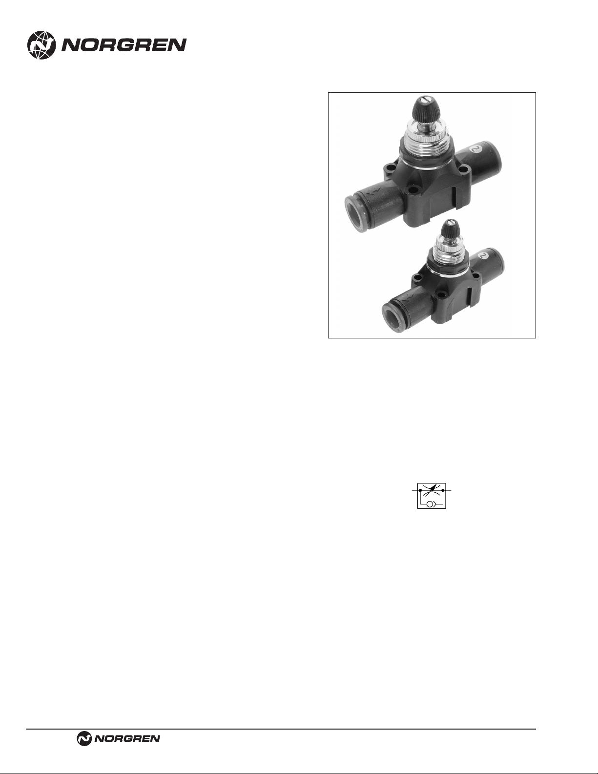
Push-In Flow Regulators
● High flow performance
● Suitable for panel/wall mounting and manifold
● Adjustment can be locked
● Captive regulator needle will not blow out when
unscrewed
● Adjusting knob position
● Releasable grab ring technology combining plastic
and brass components for a compact and superior
fitting design
● Color coding option with tamper-resistant feature
● Red release sleeve indicating metric tube sizes
● Grey release sleeve indicating inch tube sizes
● Reliable and corrosion resistant
T-15 Series
Inch and Metric O/D Tube
Technical Data
Medium: Compressed Air, filtered
Operation: Uni-directional
Operating Pressure:
1.5 to 145 psig (0.1 to 10 bar)
Ambient Temperature:
0° to 175°F (-20˚C* to 80˚C)
Consult our Technical Service for use below 35°F (2°C)
Mounting:
In-line. Panel mounted by hexagonal mounting nut. Wall mounted by
through-holes in regulator body. Manifold by quick connection
Alternative Models
Block form flow regulators, T1000 series
Heavy duty flow regulators, M/800, M/600
Precision flow regulators, M/650, M677 and S/790
Materials
1/8" (3mm), 5/32" (4mm), 3/16" (5mm), 1/4" (6mm),
5/16" (8mm), 3/8" (10mm)
Body: plastic PBT
Seals: silicone free nitrile seal, external metal parts: nickel plated brass
Internal parts: brass
Spring: stainless steel
Grab ring: stainless steel, BS 1440 Pt 2, grade 301.S21
Knob and panel nut: plastic POM
3/16" (5mm), – 1/2" (12mm)
Collet: nickel plated brass
Ordering Information
To order, quote model number from table on page
FIT-3-9, e.g. T15Y0004 to order 1/4" model.
ISO Symbol
1
2
Page 9
Littleton, CO USA Phone 303-794-2611 www.norgren.com
FIT-3-9
Function Fittings and Flow Controls
* Available in collet system
** C measured in dm3/(s.bar) Cv measured in US gal/min
Metric A B C D E F ØG
T15P0003 0.12 (3) 0.51 (13) 0.67 (17) 1.81 (46) 0.51 (13) M10x1 0.09 (2)
T15P0004 0.16(4) 0.51 (13) 0.67 (17) 1.81 (46) 0.51 (13) M10x1 0.09 (2)
T15P0005 0.20(5) 0.75 (19) 0.98 (25) 1.93 (49) 0.59 (15) M12x1 0.14 (4)
T15P0006 0.24(6) 0.75 (19) 0.98 (25) 2.17 (55) 0.59 (15) M12x1 0.14 (4)
T15P0008 0.31(8) 0.83 (21) 1.06 (27) 2.58 (66) 0.71 (18) M14x1.5 0.14 (4)
T15P0010 0.39(10) 1.04 (27) 1.34 (34) 3.02 (77) 0.94 (24) M20x1.5 0.17 (4)
T15P0012 0.47(12) 1.12 (29) 1.42 (36) 3.64 (93) 0.94 (24) M20x1.5 0.17 (4)
Inch A B C D E F ØG
T15Y0001 1/8 0.51 (13) 0.67 (17) 1.81 (46) 0.51 (13) M10x1 0.09 (2)
T15Y0002 5/32 0.51 (13) 0.67 (17) 1.81 (46) 0.51 (13) M10x1 0.09 (2)
T15Y0003 3/16 0.75 (19) 0.98 (25) 1.93 (49) 0.59 (15) M12x1 0.14 (4)
T15Y0004 1/4 0.75 (19) 0.98 (25) 2.17 (55) 0.59 (15) M12x1 0.14 (4)
T15Y0005 5/16 0.83 (21) 1.06 (27) 2.58 (66) 0.71 (18) M14x1.5 0.14 (4)
T15Y0006 3/8 1.04 (27) 1.34 (34) 3.02 (77) 0.94 (24) M20x1.5 0.17 (4)
T15Y0007 1/2 1.12 (29) 1.42 (36) 3.64 (93) 0.94 (24) M20x1.5 0.17 (4)
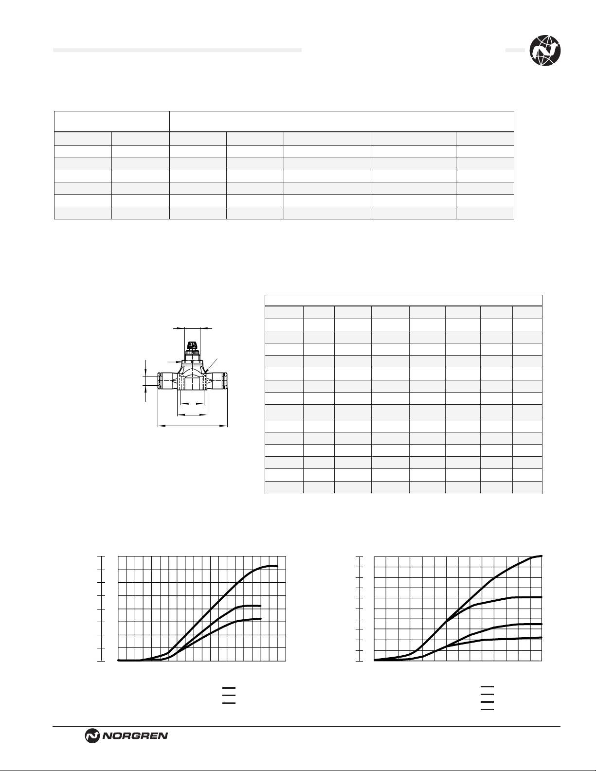
T15
Push-In Flow Regulators
T-15
Inch Metric Maxi regulated Free flow
Tube Model Tube Model flow factor Cv** factorCv** oz (kg)
1/8" T15Y0001 3 mm T15P0003 0.3 0.3 .46 (0.013)
5/32" T15Y0002 4 mm T15P0004 0.45 0.45 .46 (0.013)
3/16" T15Y0003* 5 mm T15P0005* 0.85 0.85 1.13 (0.032)
1/4" T15Y0004 6 mm T15P0006 1.3 1.3 .99 (0.028)
5/16" T15Y0005 8 mm T15P0008 2.2 2.2 1.66 (0.047)
3/8" T15Y0006 10 mm T15P0010 2.9 3.2 3.28 (0.093)
1/2" T15Y0007* 12 mm T15P0012* 5.4 5.4 .50 (0.0143)
Flow
Turns
Flow
Turns
T15-0D12-1/2
T15-0D10-3/8
T15-0D8-5/16
T15-0D6-1/4
T15-0D5-3/16
T15-0D4-5/32
T15-0D3-1/8
Flow vs turns at 6 bar - flow in dm3/s ANR
F
B
C
D
91011
flG
12
13 14 15 16 171819
E o/f
A
84.8
74.2
63.6
53.0
42.4
Flow
31.8
21.2
10.6
0
scfm
/s
3
dm
40
35
30
25
20
15
10
5
0
3456
2
1
0
78
/s
3
dm
scfm
10
21.2
9
19.0
8
17.0
7
14.8
6
12.7
5
10.6
Flow
20
8.5
6.4
4.2
2.1
4
3
2
1
0
0
0
1
3456
2
78
91011
12
13 14
Page 10
FIT-3-10
Littleton, CO USA Phone 303-794-2611 www.norgren.com
Function Fittings and Flow Controls
● In-line general purpose flow controls
● Captive adjustment needle will not blow out
when unscrewed
● Lockable, calibrated adjustment knob
● Suitable for wall mounting
● High operating pressure
C/800, M/800 Series Heavy Duty
In-Line Flow Control
Technical Data
Fluid: Compressed air, nitrogen, inert and non-combustible gases
compatible with materials of construction.
Note:
For other types of fluids or compressed gases, please
consult factory.
Operation:
Uni-directional
Mounting:
Line mounted, concentrically
Port Size:
NPT ISO G Weight lbs. (Kg)
1⁄8 NPT C/836 G1⁄8 S/836 .22 (.10)
1⁄4 NPT C/837 G1⁄4 M/837 .33 (.15)
1⁄2 NPT C/839 G1⁄2 M/839 1.32 (.60)
3⁄4 NPT C/840 G3⁄4 M/840 2.65 (1.20)
1 NPT C/855 G1 M/855 7.72 (3.50)
Operating Pressure:
5 - 230 psig (0.3 - 16 bar)
Operating Temperature:
0°* to 175°F (-20° to +80°C) (Alternative models to 300°F [150°C])
* Consult our Technical Service for use below 35°F (2°C.)
Materials
Brass body, adjusting knob, and locking ring (C/836, C/837, C/839),
aluminum body, adjusting knob and locking ring (C/840, C/855), nitrile
rubber seals.
Repair Kits
Product Number Kit Number
NPT ISO G NPT ISO G
C/836 S/836 QC/520/00 QS/520/00
C/837 M/837 QC/521/00 QS/521/00
C/839 M/839 QC/822/00 QS/522/00
C/840 M/840 QC/523/00 QS/523/00
C/855 M/855 QC/524/00 QS/524/00
Ordering Information
To order, quote model number from table on page
FIT-3-11, e.g. C/837 for the 1/4" NPT model
Alternative models
C/600 range of heavy duty panel mounting Flow
Controls (air & hydraulic), see page FIT-3-12.
T1000 range of Inline Flow Controls, see page
FIT-3-6.
TM, TC/800 High Temperature version (150° C
max.)
12
Page 11
Littleton, CO USA Phone 303-794-2611 www.norgren.com
FIT-3-11
Function Fittings and Flow Controls
Dimensions in Inches (mm)
Flow Control
ØA
Typical Model Number: C/839 1⁄2 NPT
M/839 G1⁄2
Type: Uni-directional
Free flow is from ‘2’ to ‘1’, indicated by arrow
Model Max. Regulating Max. Free
Port NPT ISO G Flow Cv Flow Cv
1/8 C/836 S/836 0.17 0.6
1/4 C/837 M/837 0.49 1.0
1/2 C/839 M/839 2.6 3.6
3/4 C/840 M/840 3.7 6.5
1 C/855 M/855 8.4 8.9
Thread NPT G A L C B M (max) D
1/8 C/836 S/836
.96 1.81 1.06 .33 3.11 .67
(25) (46) (27) (8) (79) (17)
1/4 C/837 M/837
1.63 2.36 .98 .20 1.46 .87
(42) (60) (25) (5) (37) (22)
1/2 C/839 M/839
2.25 3.7 2.09 .33 3.11 1.10
(57) (94) (53) (8) (79) (28)
3/4 C/840 M/840
2.99 4.69 2.60 .34 4.09 1.38
(76) (119) (66) (9) (104) (35)
1 C/855 M/855
3.54 5.90 4.22 .51 5.79 2.04
(90) (150) (107) (13) (147) (52)
12
13579
C/837
17.07 scfm
(6-5 bar)
C/836
5.95 scfm
(6-5 bar)
FLOW CHARACTERISTICS
FLOW
NUMBER OF TURNS
0
2
4
0
8
12
16
20
4
6
8
10
dm
3
/s
scfm
13579111315
00
100
200
300
400
50
100
150
200
dm
3
/s
scfm
C/855
324.36 scfm
(6-5 bar)
C/840
152.64 scfm
(6-5 bar)
C/839
101.97 scfm
(6-5 bar)
FLOW CHARACTERISTICS
NUMBER OF TURNS
FLOW
.51 (13)
1.10 (28)
M (max)
.67
(17)
2
.63
ØA
1.06 (27)
A/F
(16)
.52
(13)
C
A
L
B
1
Page 12

FIT-3-12
Littleton, CO USA Phone 303-794-2611 www.norgren.com
Function Fittings and Flow Controls
● Panel mounted general purpose flow controls
● Captive adjustment needle will not blow out
when unscrewed
● Calibrated adjusting knob, can be locked on 1⁄8
and 1⁄2 models
● Panel mount legend plate indicating direction of
flow control supplied as standard
● High operating pressure
C/600, M/600 Series Heavy Duty
In-Line Flow Control
Technical Data
Fluid: Compressed air, nitrogen, inert and non-combustible gases
compatible with materials of construction.
Note:
For other types of fluids or compressed gases, please
consult factory.
Operation:
Uni-directional
Mounting:
Panel mounted
Port Sizes:
NPT ISO G Weight lbs. (Kg)
1⁄8 NPT C/636 G1⁄ 8 S/636 .29 (.13)
1⁄4 NPT C/637 G1⁄4 M/637 .49 (.22)
1⁄2 NPT C/639 G1⁄2 M/639 1.72 (.78)
Operating Pressure:
5 - 230 psig (0.3 - 16 bar)
Operating Temperature:
0°* to 175°F (-20° to 80°C)
*Consult our Technical Service for use below 35°F (2°C)
Flow
Port Cv Max Cv Max
Product Size Reg Flow Free Flow
C/636 1/8" 0.17 0.51
C/637 1/4" 0.49 1.05
C/639 1/2" 2.94 4.16
Materials
Brass body, chromium plated adjusting knob, locking ring
and panel mounting ring, nitrile rubber seals.
Spares Kits
Product Number Kit Number
NPT ISO G NPT ISO G
C/636 S/636 QC/520/00 QS/520/00
C/637 M/637 QC/521/00 QS/521/00
C/639 M/639 QC/522/00 QS/522/00
Ordering Information
To order, quote model number from table on page
FIT-3-12, e.g. C/637 for the 1/4" model
Alternative models
C/800 range of Heavy duty flow controls,
see page FIT-3-10.
T1000 range of In-Line Flow Controls,
see page FIT-3-6.
TM, TC/800 high temperature version 300°F
(150°C) max.
Page 13

Littleton, CO USA Phone 303-794-2611 www.norgren.com
FIT-3-13
Function Fittings and Flow Controls
Dimensions in Inches (mm)
Panel Mounted Flow Control
ØA
Model Number: C/636 1⁄ 8 NPT
S/636 G1⁄8
Type: Uni-directional
Free flow is from ‘2’ to ‘1’, indicated by arrow
ØA
Model Number: C/637 1⁄ 4 NPT
M/637 G1⁄4
Type: Uni-directional
Free flow is from ‘2’ to ‘1’, indicated by arrow
12
Panel Mounted Flow Control
1
2
12
ØA
Model Number:
C/639 1⁄2 NPT
M/639 G1⁄2
Type: Uni-directional
Free flow is from ‘2’ to ‘1’, indicated by arrow
Panel Mounted Flow Control
1.30 (33) A/F
1.18 (30) A/F
1.18 (30)
1.50 (38)
2.13 (54)
.94 (24)
.79 (20)
1.14 (29)
.35 (9)
2.13 (54)
3.74 (95)
.35 (9)
1
2
.75 (19)
.24 (6) max.
1.75 (45) min.
2.20 (56) max.
.04 (.9)
2.72 (69)
ØA
12
1.38 (35)
0.87 (22)
.55 (14)
.04 (9) (20 SWG)
.51 (13) A/F
.83 (21)
1.54 (39) max.
1.22 (31)
1.50 (38)
.94 (24)
.69 (18)
.24 (6) max.
1.30 (33) min.
ØA
.25(6)
.94(24)
1.81 (46)
.43 (11)
.31 (8)
.55 (14)
.43 (11)
.67 (17)
.37 (10)
12
12
.71 (18) A/F
1.61 (41) max.
.04 (.9)
.91 (23)
.20 (5) max.
1.30 (33) min.
ØA
.34 (9)
1
2.13 (54)
2
1.18 (30)
.79 (20)
1.44 (37)
.50 (13)
Page 14

FIT-3-14
Littleton, CO USA Phone 303-794-2611 www.norgren.com
PIF Check Valves
● Allow free flow in one direction only
● Low cracking pressure
● PIF-PIF, PIF-Male and Male-PIF alternatives
● Non-PTFE based thread sealant on taper threads
● Releasable grab ring technology combining
plastic and brass components for a compact
and superior fitting design
● Molded mounting brackets on tub connector
designs
● Low weight design
● Red release sleeve indicating metric tube sizes
● Grey release sleeve indicating inch tube sizes
● Easy tube insertion for rapid and quick
assembly of pneumatic circuits
● Reliable and corrosion resistant
● Silicon free
● Color coding option with tamper-resistant
feature
T-51, T-52, T-53 Series
Inch and Metric O/D Tube
Technical Data
Medium: Compressed Air, filtered, lubricated or non-lubricated,vacuum
Operating Pressure:
1.5 to 145 psig (0.1 to 10 bar) (T51, T52)
4.4 to 145 psig (0.3 to 10 bar) (T53)
-1.5 to -14.5 psig (-0.1 to -1 bar) vacuum (T51, T52)
Ambient Temperature:
0° to 175°F (-20˚C* to 80˚C)
Consult our Technical Service for use below 35°F (2°C)
Mounting:
Tube/tube PIF
Tube PIF/male thread
Male threaded/tube PIF
Alternative Models
T55, T56 range of aluminum threaded non return valves.
TS/520 range of brass threaded non return valve.
Materials
5/32" – 5/16"
Body: Plastic PBT
Seal: Silicon free nitrile
Valve: Plastic PBT
Insert: Natural brass
Spring: Stainless steel
Grab Ring: Stainless steel - BS 1440
PT 2, grade 301.S21 (4-6-8 sizes)
OD-5 collet system
T-52 and T-53 series, nickel brass threads.
3/8" – 1/2" sizes
Collet: Nickel plated brass
Body: Black anodized aluminum
Valve and Insert: Aluminum
Ordering Information
To order, quote model number from table on page
FIT-3-15, e.g. T51Y0004 for the 1/4" model.
NOTE: T51 and T52 flow is threaded end to push-
in (check is in reverse).
T53 flow is from push-in to threaded end
(check is in reverse).
21
ISO Symbol
Page 15

Metric Flow factor Cracking
Model A B F ØC C/CV* pressure (bar)
T51P0004 48.8 4 15.5 4.3 0.75/0.18 0.03+0.06
T51P0005* 53.1 5 15.2 4.3 1.16/0.28 0.03+0.06
T51P0006 55.3 6 16.9 4.3 1.9/0.47 0.03+0.06
T51P0008 62.5 8 19.0 4.3 3.5/0.86 0.03+0.06
T51P0010* 77.4 10 – – 4.7/1.15 0.03+0.06
T51P0012* 88.4 12 – – 7.5/1.84 0.03+0.06
Inch Flow factor Cracking
Model A B F ØC C/CV* pressure (bar)
T51Y0002 49.8 5/32 15.5 4.3 0.75/0.18 0.03+0.06
T51Y0003* 53.1 3/16 15.2 4.3 1.16/0.28 0.03+0.06
T51Y0004 55.3 1/4 16.9 4.3 1.9/0.47 0.03+0.06
T51Y0005 62.5 5/16 19.0 4.3 3.5/0.86 0.03+0.06
T51Y0006* 77.4 3/8 – – 4.7/1.15 0.03+0.06
T51Y0007* 88.4 1/2 – – 7.5/1.84 0.03+0.06
Littleton, CO USA Phone 303-794-2611 www.norgren.com
FIT-3-15
Function Fittings and Flow Controls
Dimensions in Inches (mm)
* Available only with collet tube connection
T52, T53
T51
Inline Push-in Non Return Valves
T-51. T-52 and T-53 Series. Operating pressure: 10 bar (14 psi)
Inch Metric
PIF/Male Thrd. Model # PIF/ISO Rc Model #
5/32" x 1/8" T52A1802 4 x M5 T52M0504
3/16" x 1/8" T52A1803* 4 x 1/8" T52B1804
3/16" x 1/4" T52A2803* 5 x 1/8" T52B1805*
1/4" x 1/8" T52A1804 5 x 1/4" T52B2805*
1/4" x 1/4" T52A2804 6 x 1/8" T52B1806
5/16" x 1/8" T52A1805* 6 x 1/4" T52B2806
5/16" x 1/4" T52A2805 8 x 1/8" T52B1808
8 x 1/4" T52B2808
Inch Metric
Male Thrd./PIF Model # ISO Rc/PIF Model #
1/8 x 5/32" T53A1802 M5 x 4 T53M0504
1/8 x 3/16" T53A1803* 1/8 x 4 T53B1804
1/4 x 3/16" T53A2803* 1/8 x 5 T53B1805*
1/8 x 1/4" T53A1804 1/4 x 5 T53B2805*
1/4 x 1/4" T53A2804 1/8 x 6 T53B1806
1/8 x 5/16" T53A1805 1/4 x 6 T53B2806
1/4 x 5/16" T53A2805 1/8 x 8 T53B1808
1/4 x 8 T53B2808
Inch Metric
PIF/PIF Model # PIF/PIF Model #
5/32" T51Y0002 4 T51P0004
3/16" T51Y0003* 5 T51P0005*
1/4" T51Y0004 6 T51P0006
5/16" T51Y0005 8 T51P0008
3/8" T51Y0006* 10 T51P0010*
1/2" T51Y0007* 12 T51P0012*
** BSPT
Inch
Model A B C** G H
T52A1802 T53A1802 54.4 5/32 1/8 4 9.5
T52A1803* T53A1803* 57.9 3/16 1/8 4 9.5
T52A2803* T53A2803* 62.7 3/16 1/4 4 14.3
T52A1804 T53A1804 59.2 1/4 1/8 4 9.5
T52A2804 T53A2804 64 1/4 1/4 4 14.3
T52A1805 T53A1805 63.7 1/8 1/8 4 9.5
T52A2805 T53A2805 68.5 1/4 1/4 4 14.3
Metric
Model A B C** G H
T52M0504 T53M0504 49.2 4 M5 4 4.3
T52B1804 T53B1804 54.4 4 1/8 4 9.5
T52B1805* T53B1805* 57.9 5 1/8 4 9.5
T52B2805* T53B2805* 59.4 5 1/4 4 11
T52B1806 T53B1806 59.2 6 1/8 4 9.5
T52B2806 T53B2806 60.7 6 1/4 4 11
T52B1808 T53B1808 63.7 8 1/8 4 9.5
T52B2808 T53B2808 65.2 8 1/4 4 11
** NPTF
F
ØC
B
A
B
B
A
G H
C
Page 16

FIT-3-16
Littleton, CO USA Phone 303-794-2611 www.norgren.com
Ordering Information
To order, quote model number from table on page
FIT-3-17.
Alternative Models
T51 Series in-line push-in non-return valves, see
page FIT-3-14
● Permits free flow of air in one direction only
● Simple, reliable design
● Light weight
● Silicone free
● Low cracking pressure
● T56 male connections have an O-ring inparallel
threads
Technical Data
Medium:
Compressed air, filtered, lubricated and non-lubricated
Operation:
Non-return valve
Mounting:
Line mounted
Port Sizes:
Metric ISO G ISO Rc NPT
M5 T55M0500 G1/8 T55C1800 Rc1/8 T55B1800 1/8 NPT T55A1800
M5 T56M0500 G1/8 T56C1800 Rc1/8 T56B1800 1/8 NPT T56A1800
G1/4 T55C2800 Rc1/4 T55B2800 1/4 NPT T55A2800
G1/4 T56C2800 Rc1/4 T56B2800 1/4 NPT T56A2800
G3/8 T55C3800 Rc3/8 T55B3800 3/8 NPT T55A3800
G1/2 T55C4800 Rc1/2 T55B4800 1/2 NPT T55A4800
G3/4 TS/523 3/4 NPT TC/523
G1 TS/524 1 NPT TC/524
*High temperature viton seals
Operating Pressure:
1.5 - 145 psi (0.1 - 10 bar) T55–T56
5 - 230 psi (0.3 - 16 bar) TC/523-TC/524
Operating Temperature:
0°* to 300°F (-20°* to +150°C)
*Consult our Technical Service for use below 35°F (2˚C). For high
temperature applications (300°F [150˚C] Max) TM, TC/520 Series
version should be ordered
Materials
T55: Aluminum body (T55), brass (T56), silicone free nitrile
rubber ‘O’ ring, POM valve, stainless steel spring.
TC/TS: Brass body, aluminum valve
High temp viton seals
Non-Return Valves T55, T56 Series
In-Line, Non-Return Valves
M5, 1/8", 1/4", 3/8, 1/2" ISO G, ISO R, NPT
ISO Symbol
21
Page 17

Littleton, CO USA Phone 303-794-2611 www.norgren.com
FIT-3-17
Function Fittings and Flow Controls
Dimensions in Inches (mm)
* C measured in dm3/(s.bar) ** Cv measured in US gal/min.
EBG
C
D
D
C
A A/F
ØH
ØF
* Available only with collet tube connection
Model A B C D E F G H
T55MO500 .43 (11) 1.08 (27.5) (M5) .20 (5) .16 (4) .42 (10.7) .12 (3) .47 (12)
T55A1800 .55 (14) 1.67 (42.5) (1/8) – .28 (7) .54 (13.7) .16 (4) .59 (15)
T55B1800 .55 (14) 1.67 (42.5) (1/8) – .28 (7) .54 (13.7) .16 (4) .59 (15)
T55C1800 .55 (14) 1.67 (42.5) (1/8) .28 (7) .28 (7) .54 (13.7) .16 (4) .59 (15)
T55A2800 .67 (17) 2.13 (54) (1/4) – .31 (8) .66 (16.7) .20 (5) .73 (18.5)
T55B2800 .67 (17) 2.13 (54) (1/4) – .31 (8) .66 (16.7) .20 (5) .73 (18.5)
T55C2800 .67 (17) 2.13 (54) (1/4) .41 (10.5) .31 (8) .66 (16.7) .20 (5) .73 (18.5)
T55A3800 .94 (24) 2.48 (63) (3/8) – .35 (9) .93 (23.7) .28 (7) 1.02 (26)
T55B3800 .94 (24) 2.48 (63) (3/8) – .35 (9) .93 (23.7) .28 (7) 1.02 (26)
T55C3800 .94 (24) 2.48 (63) (3/8) .47 (12) .35 (9) .93 (23.7) .28 (7) 1.02 (26)
T55A4800 1.06 (27) 3.03 (77) (1/2) – .47 (12) 1.05 (26.7) .39 (10) 1.18 (30)
T55B4800 1.06 (27) 3.03 (77) (1/2) – .47 (12) 1.05 (26.7) .39 (10) 1.18 (30)
T55C4800 1.06 (27) 3.03 (77) (1/2) .59 (15) .47 (12) 1.05 (26.7) .39 (10) 1.18 (30)
T55 Series
Port Flow Factor Flow Factor Cracking Model
Size Cv** C* pressure (bar) oz (kg) Metric BSPP BSPT NPT
M5 0.19 0.8 0.73 (0.05) 0.35 (0.010) T55MO500
1⁄8 0.59 2.4 0.73 (0.05) 0.53 (0.015) T55C1800 T55B1800 T55A1800
1⁄4 1.35 5.5 0.73 (0.05) 0.88 (0.025) T55C2800 T55B2800 T55A2800
3⁄8 2.20 9.0 0.73 (0.05) 2.12 (0.060) T55C3800 T55B3800 T55A3800
1⁄2 3.70 15.0 0.73 (0.05) 2.82 (0.080) T55C4800 T55B4800 T55A4800
* C measured in dm3/(s.bar) ** Cv measured in US gal/min.
Model A B C D F G H I
T56MO500 .43 (11) 1.25 (31.8) (M5) .20 (5) .42(10.7) .12 (3) .47 (12) .17 (4.3)
T56A1800 .55 (14) 1.93 (49) (1/8) (–) .54 (13.7) .16 (4) .59 (15) .37 (9.5)
T56B1800 .55 (14) 1.93 (49) (1/8) (–) .54 (13.7) .16 (4) .59 (15) .37 (9.5)
T56C1800 .55 (14) 1.77 (45) (1/8) .28 (7) .54 (13.7) .16 (4) .59 (15) .22 (5.5)
T56A2800 .67 (17) 2.46 (62.5) (1/4) (–) .66 (16.7) .20 (5) .73 (18.5) .56 (14.3)
T56B2800 .67 (17) 2.32(59) (1/4) (–) .66 (16.7) .20 (5) .73 (18.5) .43 (11)
T56C2800 .67 (17) 2.21 (56.2) (1/4) .41 (10.5) .66 (16.7) .20 (5) .73 (18.5) .31 (8)
Model A B C D E
C/523 1.42 (36) 3.6 (92) 3⁄4 .71 (18) .71 (18)
S/523 1.42 (36) 3.6 (92) 3⁄4 .71 (18) .71 (18)
C/524 1.93(49) 4.88 (124) (1) .98 (25) .98 (25)
S/524 1.93(49) 4.88 (124) (1) .98 (25) .98 (25)
T56 Series
Port Flow Factor Flow Factor Cracking Model
Size Cv** C* pressure (bar) oz (kg) Metric BSPP BSPT NPT
M5 0.19 0.55 0.73 (0.05) 0.64 (0.018) T56MO500
1⁄8 0.59 2.4 0.73 (0.05) 1.59 (0.045) T56C1800 T56B1800 T56A1800
1⁄4 1.23 5.0 0.73 (0.05) 2.82 (0.080) T56C2800 T56B2800 T56A2800
DE
B
C
C
A
‘1’ ‘2’
Model Port Flow factor Cracking Weight Spares Kit
NPT ISO G Size Cv Pressure psi (bar) lbs. (kg) NPT ISO G
C/523 S/523 3⁄4 6.5 0.9 (0.06) 1.21 (.55) QC/523/00 QS/523/00
C/524 S/524 1 8.9 0.9 (0.06) 2.43 (1.10) QC/524/00 QS/524/00
Note : For high temperature applications a T should be added on spares kit part number (i.e. TQS/520/00)
Initial cracking pressure may be higher if valve has been stored for a long period.
C/523 – C/524 Series
B
I
G
E
A
A/F
C
ØF
C
D
ØH
Page 18

FIT-3-18
Littleton, CO USA Phone 303-794-2611 www.norgren.com
Function Fittings and Flow Controls
● Assists in complying with OSHA and related
safety regulations
● Tamper proof
● Compact
● Low pressure drop
● Automatically resets after failure correction
● High air pressure rating
T60 Air Fuse
1⁄4" to 1-1⁄2" NPT, ISO G
Technical Data
Fluid: Compressed air, nitrogen, inert and non-combustible gases
compatible with materials of construction.
Note:
For other types of fluids or compressed gases, please
consult factory.
Operation:
Fixed uni-directional excess flow automatic shut off valve (air fuse)
Mounting:
In-line two way valve
To be inserted between fixed air supply and flexible air lines
See guidelines for typical installation
Port Size: Female Thread
NPT ISO G
1⁄4 NPT T60A289* G 1⁄4 T60C289*
3⁄8 NPT T60A389* G 3⁄8 T60C389*
1⁄2 NPT T60A489* G 1⁄2 T60C489*
3⁄4 NPT T60A689* G 3⁄4 T60C689*
1 NPT T60A889* G 1 T60C889*
1-1⁄2 NPT T60AB89* G 1-1⁄2 T60CB89*
* Last digit depends on flow range
Operating Pressure:
Maximum 232 psi (16 bar)
Minimum according to hose length
Drop pressure at shut-off flow: 2 to 4.5 psi (0.14 or 0.3 bar)
Operating Temperature:
0°** to 175° F (-20° to 80°C)
**Consult our Technical Service for use below 35°F (2˚C)
At low temperature ensure air fuse is not subjected to freezing
conditions which may prevent its function.
Materials
Aluminium body, brass internal parts, stainless steel spring
Ordering Information
To order, quote appropriate product number
from the tables on the following pages.
i.e. T60A2890 for the 1⁄4 NPT with 2 psi
pressure drop at shut off.
T60A2890
Thread
Type
1
Thread
Size
Flow
Range
2
2
Series
Number
Simplified Symbol
1
ISO Symbol
Page 19

Littleton, CO USA Phone 303-794-2611 www.norgren.com
FIT-3-19
Function Fittings and Flow Controls
Dimensions in Inches (mm)
General Information
Air Fuse
(Excess Flow Check)
Drop pressure at Shut off flow rate Flow at 100 psi (7 bar)
Model shut off flow at ∆P 1 psi (0.07 bar) Weight
NPT ISO G Port size psi (bar) 100 psi (7 bar) scfm (dm3/s) oz. (Kg)
T60A2890 T60C2890
1⁄4
2.0 (.14) 17.6 (8) 13.8 (7) 1.4 (.04)
T60A2891 T60C2891 4.4 (.3) 29.7 (14) 13.8 (7) 1.4 (.04)
T60A3890 T60C3890
3⁄8
2.0 (.14) 41.1 (19) 28.6 (14) 2.3 (.07)
T60A3891 T60C3891 4.4 (.3) 68.2 (32) 28.6 (14) 2.3 (.07)
T60A4890 T60C4890
1⁄2
2.0 (.14) 68.2 (32) 49.2 (23) 5.3 (.15)
T60A4891 T60C4891 4.4 (.3) 102.3 (48) 49.2 (23) 5.3 (.15)
T60A6890 T60C6890
3⁄4
2.0 (.14) 102.3 (48) 91.1 (43) 4.6 (.13)
T60A6891 T60C6891 4.4 (.3) 169.5 (80) 91.1 (43) 4.6 (.13)
T60A8890 T60C8890
1
2.0 (.14) 195.0 (92) 144 (68) 19.0 (.54)
T60A8891 T60C8891 4.4 (.3) 271.0 (128) 144 (68) 19.0 (.54)
T60AB890 T60CB890
1-1⁄2
2.0 (.14) 394.0 (186) 307 (145) 38.8 (1)
T60AB891 T60CB891 4.4 (.3) 568.0 (268) 307 (145) 38.8 (1)
NPT : according to ANSI-B1.20.1.
ISO G : according to BS2779 and ISO-228/1
Flow and pressure test conducted according to ISO-6358 test circuit. Mean measured flow values are provided at
standard reference conditions.
B
C
D
D
C
A A/F
F
E
Model T60A289* T60C289* T60A389* T60C389* T60A489* T60C489* T60A689* T60C689* T60A889* T60C889* T60AB89* T60CB89*
NPT ISO G NPT ISO G NPT ISO G NPT ISO G NPT ISO G NPT ISO G
A
0.81 0.81 0.94 0.94 1.25 1.25 1.25 1.25 2.00 2.00 2.50 2.50
(21) (21) (24) (24) (32) (32) (32) (32) (51) (51) (64) (64)
B
2.01 2.01 2.44 2.44 3.07 3.07 3.54 3.54 4.65 4.65 5.71 5.71
(51) (51) (62) (62) (78) (78) (90) (90) (118) (118) (145) (145)
C 1/4 1/4 3/8 3/8 1/2 1/2 3/4 3/4 1.0 1.0 1.5 1.5
D
0.39 0.43 0.41 0.55 0.59 0.54 0.56 0.75 0.66 1.00 0.68 1.00
(10) (11) (10) (14) (15) (14) (14) (19) (17) (26) (17) (26)
E
0.12 0.12 0.20 0.20 0.20 0.20 0.20 0.20 0.20 0.20 0.20 0.20
(3) (3) (5) (5) (5) (5) (5) (5) (5) (5) (5) (5)
F
0.81 0.81 0.94 0.94 1.25 1.25 1.25 1.25 2.00 2.00 2.50 2.50
(21) (21) (24) (24) (32) (32) (32) (32) (51) (51) (64) (64)
Page 20

FIT-3-20
Littleton, CO USA Phone 303-794-2611 www.norgren.com
Function Fittings and Flow Controls
Guidelines for Typical Installation
The air fuse should be installed directly between fixed or rigid pipework and the flexible tube to protect the whole
length of the flexible tube. Only tubing after the air fuse is protected. The air fuse must be installed in the correct
orientation. Failure to do this will render it ineffective. When a shut off valve is located before the air fuse, the
valve must be opened slowly in order to control initial air flow and avoid decompression effects which may trip the
air fuse.
It should be noted that the OSHA standard (29 CFR ChXVII Para 1926.302-b7) relating to pneumatic power tools
states “All hoses exceeding 1/2" inside diameter shall have a safety device at the source of supply or branch
line to reduce pressure in the case of hose failure.”
Choosing an Air Fuse*
a) The port size of the air fuse should be nominally equal to that of the supply lines - e.g. a 1⁄2 (12.7 mm) air fuse
should be used with a 1⁄2'' (12.7mm) ID hose.
b) Always select the high flow model (91) if there is sufficient system pressure for the length of hose to be
protected. See tables hose length vs. minimum supply pressure.
c) If there is insufficient system pressure, or long hose lengths are to be protected, use model 90.
d) After installation always test each valve for proper function. See section below on how to check an air fuse.
e) The pneumatic system must be capable of delivering the flow required to activate the air fuse. For this reason,
the air fuse is not suitable for use with the Norgren R07 miniature range in certain installations.
f) For use with spring coils consult table. See table flow vs. pressure supply.
Verifying Operation of an air fuse
● Install the air fuse following the instructions supplied
● Connect tool or complete circuit to the air line
● Switch on operation to ensure a complete cycle is performed
● If tool or complete circuit starts and runs satisfactorily, stop operation and drain air line. Disconnect hose from
tool or circuit and secure hose end. Turn on air supply progressively (to avoid decompression effect). Prior to
fully reaching operation conditions, the air fuse should suddenly activate and cut off the flow. A slight air flow
will remain as part of the automatic re-set function. If the air fuse is not activated the unit should be
disconnected and the lower flow range air fuse should be used.
* Consult factory for the availability of Excel™ based sizing program.
AIR SUPPLY
TOOL
TOOL
TOOL
TOOL
TOOL
TOOL
RIGID LINE FLEXIBLE LINE
Air Fuse
Air Fuse
Air Fuse
Air Fuse
Air Fuse
Air Fuse
Page 21

Littleton, CO USA Phone 303-794-2611 www.norgren.com
FIT-3-21
Function Fittings and Flow Controls
Flow (±10%) vs pressure supply (1⁄4 to 1⁄2)
Hose length vs
minimum pressure supply
(1⁄4 to 3⁄8)
Hose length vs
pressure supply
(1 to 1-1⁄2)
Hose length vs
minimum pressure supply
(1⁄2 to 3⁄4)
Flow (±10%) vs pressure supply (3⁄4 to 1-1⁄2)
KEY
— 6 - T60 * 6890
— 7 - T60 * 6891
— 8 - T60 * 8890
— 9 - T60 * 8891
— 10 - T60 * B890
— 11 - T60 * B891
KEY
— 1 - T60 * 2890
— 2 - T60 * 2891
— 3 - T60 * 3890
— 4 - T60 * 3891
— 4 - T60 * 4890
— 5 - T60 * 4891
KEY
1 - T60 * 2890 ID = 0.30'' (7.5mm)
2 - T60 * 2891 ID = 0.30'' (7.5mm)
3 - T60 * 3890 ID = 0.35'' (9.0mm)
4 - T60 * 3891 ID = 0.35'' (9.0mm)
KEY
— 9 - T60 * 8890 ID = 1.00'' (25.0mm)
— 10 - T60 * 8891 ID = 1.00'' (25.4mm)
— 11 - T60 * B890 ID = 1.50'' (38.1mm)
— 12 - T60 * B891 ID = 1.50'' (38.1mm)
KEY
5 - T60 * 4890 ID = 0.51'' (13mm)
6 - T60 * 4891 ID = 0.51'' (13mm)
7 - T60 * 6890 ID = 0.75'' (19mm)
8 - T60 * 6891 ID = 0.75'' (19mm)
(12) 174
(11) 160
(10) 145
(9) 131
(8) 116
(7) 102
(6) 87
(5) 73
(4) 58
(3) 44
(2) 29
(1) 15
0
(13) 189
(14) 203
(bar) psi
1
2
3
4
(1)
(2) (3) (4) (5) (6) (7) (8) (9) (10) meters
3
7101316 202326
30 33 feet
Hose Length
Pressure Supply
0
Hose Length
Pressure Supply
7
5
8
6
(6) 87.0
(5.5) 79.8
(5) 72.5
(4.5) 65.3
(4) 58.0
(3.5) 50.8
(3) 43.5
(2.5) 36.3
(2) 29.0
(1.5) 21.8
(1) 14.5
(6.5) 94.3
(7) 101.5
(7.5) 108.8
(8) 116.0
(2) (4) (6) (8) (10) (12) (14) (16) (18) (20)
7 132026333946535966
feet
meters
(0.5) 7.3
(bar) psi
Measurements
- Flow and pressure tests conducted according to
ISO-6358 test circuit
- Mean measured flow values are provided at standard
reference condition 68°F, 15 psi, (20°C, 1.01 bar)
- Indicated pressure values are relative pressure in bar.
Hose Lengths
- Graphs are for indicated hose internal diameter in key.
- Consult our Technical Service for hose lengths and
Internal diameters different from the recommended one.
Pressure Supply
(bar) psi
(3.5) 50.8
(3.0) 43.5
(2.5) 36.3
(2.0) 29.0
(1.5) 21.8
(1.0) 14.5
(0.5) 7.3
0
7 132026333946535966
(2) (4) (6) (8) (10) (12) (14) (16) (18) (20)
Hose length
10
12
9
11
feet
meters
Shut Off Flow
(dm3/s) scfm
(75) 159
(70) 148
(65) 138
(60) 127
(55) 117
(50) 106
(45) 95
(40) 85
(35) 74
(30) 64
(25) 53
(20) 42
(15) 32
(10) 21
(5) 10.6
0
29 58 87 116 145 174 203 232
(2)
(6)
(4)
Pressure Supply
(8)
(10)
(12) (14) (16)
5
4
3
2
1
psi
(bar)
Shut Off Flow
(dm3/s) scfm
(600) 1272
(550) 1166
(500) 1060
(450) 954
(400) 848
(350) 742
(300) 636
(250) 530
(200) 424
(150) 318
(100) 212
(50) 106
0
29 58 87 116 145 174 203 232
(2)
(6)
(4)
(10)
(8)
Pressure Supply
(12) (14) (16)
11
10
9
8
7
6
psi
(bar)
Page 22

FIT-3-22
Littleton, CO USA Phone 303-794-2611 www.norgren.com
Function Fittings and Flow Controls
Valve Thread Hose length Internal Hose Diamter (inch)
Model Size Feet 0.125 0.188 0.215 0.250 0.313 0.370 0.470 0.500 0.590 0.750 1.000 1.250 1.500
T60*2890 1/4 12 124 64 29 16 11 8 8 8 7777
T60*2890 1/4 25 126 52 25 14 9 9 8 7777
T60*2890 1/4 50 244 97 42 21 11 10 8 8777
T60*2890 1/4 100 187 76 35 15 13 10 8777
T60*2891 1/4 12 70 31 17 10 9 8 7777
T60*2891 1/4 25 137 57 27 13 11 9 8777
T60*2891 1/4 50 107 47 19 15 11 8777
T60*2891 1/4 100 207 87 30 23 14 9877
T60*3890 3/8 12 125 52 25 12 11 9 8777
T60*3890 3/8 25 102 45 18 15 10 8777
T60*3890 3/8 50 196 82 29 22 14 9877
T60*3890 3/8 100 157 50 38 20 11 8 7 7
T60*3891 3/8 12 132 57 21 17 11 8877
T60*3891 3/8 25 111 37 28 16 10 8 7 7
T60*3891 3/8 50 215 67 49 25 12 8 8 7
T60*3891 3/8 100 126 91 42 17 9 8 7
T60*4890 1/2 12 132 57 21 17 11 8877
T60*4890 1/2 25 111 37 28 16 10 8 7 7
T60*4890 1/2 50 215 67 49 25 12 8 8 7
T60*4890 1/2 100 126 91 42 17 9 8 7
T60*4891 1/2 12 119 39 30 17 10 8 7 7
T60*4891 1/2 25 74 54 27 13 8 8 7
T60*4891 1/2 50 141 102 46 18 10 8 8
T60*4891 1/2 100 196 85 29 12 9 8
T60*6890 3/4 12 119 39 30 17 10 8 7 7
T60*6890 3/4 25 74 54 27 13 8 8 7
T60*6890 3/4 50 141 102 46 18 10 8 8
T60*6890 3/4 100 196 85 29 12 9 8
T60*6891 3/4 12 96 70 33 15 9 8 7
T60*6891 3/4 25 193 139 62 23 11 8 8
T60*6891 3/4 50 116 38 14 9 8
T60*6891 3/4 100 224 69 20 11 9
T60*8890 1 12 123 89 41 17 9 8 7
T60*8890 1 25 178 78 27 12 9 8
T60*8890 1 50 148 47 16 10 8
T60*8890 1 100 88 24 13 9
T60*8891 1 12 231 166 73 26 11 8 8
T60*8891 1 25 144 46 16 10 8
T60*8891 1 50 85 24 12 9
T60*8891 1 100 163 41 17 11
T60*B890 1-1/2 12 147 47 16 10 8
T60*B890 1-1/2 25 90 25 13 9
T60*B890 1-1/2 50 173 43 18 11
T60*B890 1-1/2 100 78 29 16
T60*B891 1-1/2 12 89 25 13 9
T60*B891 1-1/2 25 179 44 18 12
T60*B891 1-1/2 50 81 30 16
T60*B891 1-1/2 100 154 52 24
Coiled hose selection table
Selection procedure for coiled hose:
Chose the thread size of your hose, the hose internal diameter in inches and the hose length in feet. The minimum
supply pressure in psi is shown in the table below and the appropriate air fuse is shown in the left column. The “*” in
the middle of the part number represents the thread type - put an “A” for NPT and a “C” for ISO G threads. If no
value is shown, it may not be possible to protect your hose with an air fuse. If in doubt, consult a Norgren distributor
or Norgren.
Page 23

Littleton, CO USA Phone 303-794-2611 www.norgren.com
FIT-3-23
● Compact size
● Easy tube insertion for rapid assembly of
pneumatic circuits
● Push-in and threaded ports
● Optimum pressure utilization
● Safer pneumatic systems
● Hex key adjustment and locking ring
● Relieving
Technical Data
Fluid: Compressed air, nitrogen, inert and non-combustible gases
compatible with materials of construction.
Note:
For other types of fluids or compressed gases, please
consult factory.
Operating Pressure:
Primary (inlet) pressure 0 to 150 psi (0 - 10 bar)
Maximum secondary (regulated) pressure 115 psi (8 bar)
Operating Temperature:
0° to 175°F (-20° to +80°C)
Outlet Port:
5/32'', 1⁄4'', 5/16'', 3⁄8'', 1/2” O.D. tube Push-in Fittings
1/8, 1⁄4, 3⁄8, 1/2 NPTF Threaded Ports
4, 6, 8, 10mm O.D. tube Push-in Fittings
Inlet Port:
1/8, 1⁄4, 3⁄8, 1/2 NPTF Thread
1/8, 1⁄4, 3⁄8, 1/2 ISO G Thread
Tubing Types:
Nylon 11 or 12, polyurethane (95 durometer or above)
LDPE (Low Density Polyethylene)
Materials
Nickel plated brass body
Nickel plated brass collet
Plastic sealing washer
Nitrile and polyurethane elastomeric parts
Zinc plated brass banjo bolt
Function Fittings and Flow Controls
Pressure Reducing Fitting
Inch and Metric
Ordering Information
To order, quote appropriate product number
from the tables on the following pages.
Product numbering system is designed to
make identification and selection simple:
12_______
Series
Number
Type
Shape
Tube Size/
Thread Size
Thread Size/
Tube Size
124GB
124GB
Port 1
Port 2
2
1
Page 24

FIT-3-24
Littleton, CO USA Phone 303-794-2611 www.norgren.com
Function Fittings and Flow Controls
Dimensions in Inches (mm)
C
A
H
E
B
G
I
D
2
1
J
O.D. Tube
Pressure Reducing Fitting - 124GB
AB
Part O/D NPT D E H SQ J
Number Tube Thread C (max) A/F G A/F I A/F
12 4GB 0218 5⁄32 1⁄8
0.89 2.87 0.67
–
0.63 0.78 0.20
(23) (73) (17) (16) (20) (5)
12 4GB 0418 1⁄4 1⁄8
0.91 2.87 0.67
–
0.63 0.78 0.20
(23) (73) (17) (16) (20) (5)
12 4GB 0428 1⁄4 1⁄4
1.0 3.10 0.67 0.64 0.79 1.02 0.20
(25) (79) (17) (16) (20) (26) (5)
12 4GB 0528 5⁄16 1⁄4
1.03 3.10 0.67 0.64 0.79 1.02 0.20
(26) (79) (17) (16) (20) (26) (5)
12 4GB 0538 5⁄16 3⁄8
1.11 3.35 0.87 0.69 0.94 1.14 0.34
(28) (85) (22) (18) (24) (29) (6)
12 4GB 0638 3⁄8 3⁄8
1.29 3.35 0.87 0.69 0.94 1.14 0.34
(33) (85) (22) (18) (24) (29) (6)
12 4GB 0748 1⁄2 1⁄2
1.56 3.54 1.06
–
1.18 1.38 0.24
(40) (90) (27) (30) (35) (6)
1) Inlet Port
2) Outlet Port
Note: For mounting in ports 2 & 4 of a pneumatic directional control valve
C
A
H
E
B
G
I
D
2
1
J
Pressure Reducing Fitting - 124GB
AB
Part NPT NPT D E H SQ J
Number Thread Thread C (max) A/F G A/F I A/F
12 4GB 1818 1⁄8 1⁄8
0.83 2.87 0.67
–
0.64 0.78 0.20
(21) (73) (17) (16) (20) (5)
12 4GB 2828 1⁄4 1⁄4
1.14 3.10 0.67 0.64 0.79 1.02 0.20
(29) (79) (17) (16) (20) (26) (5)
12 4GB 3838 3⁄8 3⁄8
1.20 3.35 0.87 0.69 0.94 1.14 0.24
(31) (85) (22) (18) (24) (29) (6)
12 4GB 4848 1⁄2 1⁄2
1.54 3.54 1.06
–
1.18 0.98 0.24
(39) (90) (27) (30) (35) (6)
1) Inlet Port
2) Outlet Port
Note: For mounting in ports 2 & 4 of a pneumatic directional control valve
C
A
H
E
B
G
I
D
2
1
J
Pressure Reducing Fitting - 102GB
AB
Part O/D ISO G D E H SQ J
Number tube Thread C (max) A/F G A/F I A/F
10 2GB 0418 4 1⁄8
0.89 2.87 0.67 0.25 0.64 0.78 0.20
(22) (73) (17) (6) (16) (20) (5)
10 2GB 0628 61⁄4
1.00 3.54 0.67 0.41 0.79 1.02 0.20
(25) (90) (17) (11) (20) (26) (5)
10 2GB 0828 81⁄4
1.03 3.54 0.67 0.41 0.79 1.02 0.20
(26) (90) (17) (11) (20) (26) (5)
10 2GB 0838 83⁄8
1.11 3.78 0.87 0.43 0.94 1.14 0.24
(28) (96) (22) (11) (24) (29) (6)
10 2GB 1038 10 3⁄8
1.29 3.78 0.87 0.43 0.94 1.14 0.24
(33) (96) (22) (11) (24) (29) (6)
AB
Part ISO G ISO G D E H SQ J
Number Thread Thread C (max) A/F G A/F I A/F
10 2GB 1818 1⁄8 1⁄8
0.69 2.87 0.67 0.25 0.64 0.78 0.20
(18) (73) (17) (6) (16) (20) (5)
10 2GB 2828 1⁄4 1⁄4
0.96 3.19 0.37 0.41 0.79 1.02 0.20
(25) (81) (17) (11) (20) (26) (5)
10 2GB 3838 3⁄8 3⁄8
1.06 3.46 0.87 0.43 0.94 1.14 0.24
(27) (88) (22) (11) (24) (29) (6)
10 2GB 4848 1⁄2 1⁄2
1.34 3.50 1.06 0.37 1.18 1.42 0.24
(34) (89) (27) (10) (30) (36) (6)
1) Inlet Port
2) Outlet Port
Note: For mounting in ports 2 & 4 of a pneumatic directional control valve
Page 25

Littleton, CO USA Phone 303-794-2611 www.norgren.com
FIT-3-25
Function Fittings and Flow Controls
Flow characteristics at primary pressure of 100 psi (7 bar)
Inch and Metric Versions
(bar) psi
(6) 87.0
(5) 72.5
(4) 58.0
(3) 43.5
(2) 29.0
(1) 14.5
1/8 Pipe
Secondary pressure
0
0
7
(200)
Flow
14
(400)
21
(600)
scfm
(l/min)
(bar) psi
(6) 87.0
(5) 72.5
(4) 58.0
(3) 43.5
(2) 29.0
(1) 14.5
1/4 Pipe
Secondary pressure
0
0 10 20 30 40
(283)
(566) (850) (1132)
Flow
50
(1415)
scfm
(l/min)
(bar) psi
(6) 87.0
(5) 72.5
(4) 58.0
(3) 43.5
(2) 29.0
(1) 14.5
3/8 and 1/2 Pipe
Secondary pressure
0
0 20 40
(566) (1132)
Flow
60
(1699)
scfm
(l/min)
Page 26

FIT-3-26
Littleton, CO USA Phone 303-794-2611 www.norgren.com
Function Fittings and Flow Controls
● Compact size
● Easy tube insertion for rapid assembly of
pneumatic circuits
● Positive tube retention
● Safer pneumatic systems
● Push-in and threaded ports
Pilot Operated Check Valve
Inch and Metric
Technical Data
Fluid: Compressed air, nitrogen, inert and non-combustible gases
compatible with materials of construction.
Note:
For other types of fluids or compressed gases, please
consult factory.
Operating Pressure:
15-150 psi (1 - 10 bar)
Operating Temperature:
0° to 175°F (-20° to +80°C)
Inlet Port:
1⁄4'', 3⁄8'', 1⁄2'' O.D. tube Push-in Fittings
1⁄8, 1⁄4, 3⁄8, 1⁄2 NPTF Threaded Ports
6, 8, 10, 12mm O.D. tube Push-in Fittings
Outlet Port:
1⁄8, 1⁄4, 3⁄8, 1⁄2 NPTF Thread*
1⁄4, 3⁄8, 1⁄2 ISO G Thread
Signal Port:
10-32 UNF on NPT ported models
M5 on metric models
Tube Sizes
1⁄4'', 3⁄8'', 1⁄2'' O/D
6, 8, 10, 12mm O/D
Tubing Types:
Nylon 11 or 12, polyurethane (95 durometer or above), and
LDPE (Low Density Polyethylene)
Materials
Nickel plated brass body
Nickel plated brass collet
Plastic sealing washer (ISO G)
Nitrile and polyurethane elastomeric parts
Zinc plated brass banjo bolts
Ordering Information
To order, quote appropriate product number
from the tables on the following pages.
Product numbering system is designed to
make identification and selection simple:
12_______
Series
Number
Type
Shape
Tube Size/
Thread Size
Thread Size/
Tube Size
124GA
124GA
Flow Rates (scfm)
Port Size 1/8 1/4 3/8 1/2
From 2 to 1
10.2 23.9 40.8 67.4
P12 = 88 psi
From 1 to 2
4.5 21.8 41.3 66.7
P12 = 0 psi
Pilot
Port 2
Port 1
NPTF Maximum
Thread TIghtening Torque
(male) ft lbs (Nm)
1/8 5 (7)
1/4 11 (15)
3/8 14 (20)
1/2 14 (20)
* Male NPTF threads (port 2) should be assembled hand tight and then
wrenched no more than 1/2 to 3/4 turn.
2
12
1
Page 27

Littleton, CO USA Phone 303-794-2611 www.norgren.com
FIT-3-27
Function Fittings and Flow Controls
E
A
J
G
I
D
H
C
12
1
2
B
Inch O.D. Tube x NPTF thread
Pilot Operated Check Valve - 124GA
AB
Product O.D. NPT E H SQ
Number Tube Thread C D A/F G A/F I J
12 4GA 0418 1⁄4" 1⁄8
0.91 1.61 0.51 0.48 0.63 0.78
10-32 UNF
(23) (41) (13) (12) (16) (20)
12 4GA 0428 1⁄4" 1⁄4
0.99 1.89 0.67 0.64 0.79 1.02
10-32 UNF
(25) (48) (17) (16) (20) (26)
12 4GA 0638 3/8" 3/8
1.29 2.16 0.87 0.69 0.94 1.14
10-32 UNF
(33) (55) (22) (18) (24) (29)
12 4GA 0748 1⁄2" 1⁄2
1.56 2.58 1.06 0.87 1.18 1.42
10-32 UNF
(40) (66) (27) (22) (30) (36)
1) Inlet Port
2) Outlet Port
12) Signal Port
Note: For mounting in pairs on a cylinder
1) Inlet Port
2) Outlet Port
12) Signal Port
Note: For mounting in pairs on a cylinder
E
A
J
G
I
D
H
C
12
1
2
B
Pilot Operated Check Valve - 124GA
AB
Product NPT NPT G HSQ
Number Thread Thread C D E A/F A/F I J
12 4GA 1818
1⁄8
1⁄8
0.87 1.61 0.51 0.48 0.63 0.78
10-32 UNF
(22) (41) (13) (12) (16) (20)
12 4GA 2828
1⁄4
1⁄4
1.14 1.89 0.67 0.64 0.79 1.02
10-32 UNF
(29) (48) (17) (16) (20) (26)
12 4GA 3838
3⁄8
3⁄8
1.20 2.17 0.87 0.69 0.94 1.14
10-32 UNF
(31) (55) (22) (18) (24) (29)
12 4GA 4848
1⁄2
1⁄2
1.54 2.58 1.06 0.87 1.18 1.42
10-32 UNF
(39) (66) (27) (22) (30) (36)
Dimensions in Inches (mm)
E
A
J
G
I
D
H
C
12
1
2
B
mm O.D. tube x ISO G thread
Pilot Operated Check Valve - 102GA
AB
Product O/D ISO G E HSQ
Number tube Thread C D A/F G A/F I J
10 2GA 0628 1⁄4
0.99 1.87 0.67 0.41 0.79 1.02
M5
6
(25) (48) (170) (11) (20) (26)
10 2GA 0828 1⁄4
1.03 1.87 0.67 0.41 0.79 1.02
M5
8
(26) (48) (17) (11) (20) (26)
10 2GA 0838 3⁄8
1.11 2.15 0.87 0.43 0.94 1.14
M5
8
(28) (55) (22) (11) (24) (29)
10 2GA 1038 3⁄8
1.29 2.15 0.87 0.43 0.94 1.14
M5
10
(33) (55) (22) (11) (24) (29)
10 2GA 1248 1⁄2
1.56 2.56 1.06 0.50 1.18 1.42
M5
12
(40) (65) (27) (13) (30) (36)
1) Inlet Port
2) Outlet Port
12) Signal Port
Note: For mounting in pairs on a cylinder
Signal Pressure
Secondary Pressure
(1) (4) (5) (6) (7) (8) (9)(2) (3)
1/2"
3/8"
(bar) psi
(6) 87.0
(5) 72.5
(4) 58.0
(3) 43.5
(2) 29.0
(1) 14.5
0
87.0
72.5
58.0
43.529.014.5
101.5
116.0 130.5
(bar)
psi
1/8" & 1/4"
Page 28

FIT-3-28
Littleton, CO USA Phone 303-794-2611 www.norgren.com
Function Fittings and Flow Controls
● Compact units
● Easy tube insertion for rapid assembly of
pneumatic circuits
● Positive tube retention
● Simplifies pneumatic systems
● Eliminates need for electrical reed switches
● Exhausts on signal side (port 2)
Pressure Sensor Fitting
Inch and Metric
Technical Data
Fluid: Compressed air, nitrogen, inert and non-combustible gases
compatible with materials of construction.
Note:
For other types of fluids or compressed gases, please
consult factory.
Operating Pressure:
Cylinder pressure (Pc) 145 psi (10 bar) max
Sensor supply pressure 43 to 145 psi (3 - 10 bar)
Sensor switch pressure 14.5 psi (1.0 bar) typical
Operating Temperature:
0° to 175°F (–20° to +80°C)
Body Ports
5⁄32'' O.D. tube Push-in
4mm O.D. tube Push-in
1⁄8, 1⁄4 NPTF Banjo Bolt
1⁄8, 1⁄4 ISO G Banjo Bolt
Tube Sizes
5⁄32'' O/D
4mm O/D
Tubing Types:
Nylon 11 or 12, polyurethane (95 durometer or above)
and LPDE (Low Density Polyethylene)
Materials
Body, swivel fitting and collet: Nickel plated brass
O-ring: Silicone free Nitrile
Sealing washer (parallel male threads): Thermoplastic
Tubing: Nylon 11 or 12, Polyurethane (95 durometer or above) and LDPE
(Low Density Polyethylene).
Note: Lower durometer polyurethane may be used, however, an internal
tube support is required to prevent internal collapse of the tube wall.
Ordering Information
To order, quote appropriate product number from
the tables on the following pages.
Product numbering system is designed to make
identification and selection simple:
124GD
124GD
12_______
Series
Number
Type
Shape
Tube Size/
Thread Size
Thread Size/
Tube Size
2
1
Page 29

Littleton, CO USA Phone 303-794-2611 www.norgren.com
FIT-3-29
Function Fittings and Flow Controls
Dimensions in Inches (mm)
mm O.D. tube x ISO G Banjo Bolt
Pressure Sensor Fitting- 102GD
This sensor fitting produces an end of stroke signal when exhaust back pressure in a cylinder
decays below a set value. It should be mounted directly on the cylinder and can be used with a
flow control device mounted into the top port.
It is recommended that the sensor supply pressure to port 1 be the same as the nominal working
pressure of the cylinder.
J 13.220
D BSPP
ØG
H
Inch O.D. tube x NPTF Banjo Bolt
Pressure Sensor Fitting- 124GD
This sensor fitting produces an end of stroke signal when exhaust back pressure in a
cylinder decays below a set value. It should be mounted directly on the cylinder and
can be used with a flow control device mounted into the top port.
It is recommended that the sensor supply pressure to port 1 be the same as the
nominal working pressure of the cylinder.
J 13.220
D BSPP
ØG
H
I
AB E
Product Tube
NPT
NPT J
Number O/D Thread C D Thread F G H I A/F
12 4GD 0218 5/32" 1⁄8
0.35 1.77
1⁄8
0.39 0.39 0.83 1.12
9/16''
(9) (45) (10) (10) (21) (29)
12 4GD 0228 5/32" 1⁄4
0.43 1.85
1⁄4
0.39 0.56 0.83 1.33
3/4''
(11) (47) (10) (14) (21) (34)
AB E
Product Tube
ISO G
ISO G J
Number O/D Thrd C D thread F G H I A/F
10 2GD 0418 41⁄8
0.35 1.77
1⁄8
0.39 0.24 0.83 0.98 0.59
(9) (45) (10) (6) (21) (25) (15)
10 2GD 0428 41⁄4
0.43 1.85
1⁄4
0.39 0.28 0.83 1.14 0.75
(11) (47) (10) (7) (21) (29) (19)
J
E
G
B
C
D
2
A
H
F
1
A
J
I
E
G
B
C
D
2
A
H
F
1
A
Page 30

FIT-3-30
Littleton, CO USA Phone 303-794-2611 www.norgren.com
Function Fittings and Flow Controls
● Enables air to be exhausted quickly from air
reservoirs and cylinders
● Allows higher cylinder speeds to be achieved
● Simple, compact design and construction
● Reliable operation
T70 Series Quick Exhaust Valves
Technical Data
Fluid:
Compressed air, filtered, lubricated and non-lubricated
Operation:
Diaphragm
Mounting:
Line mounted
Port Size:
Female Thread
(Inlet, outlet and exhaust ports)
NPT ISO G
1⁄8 NPT T70A1800 G1⁄8 T70C1800
1⁄4 NPT T70A2800 G1⁄4 T70C2800
3⁄8 NPT T70A3800 G3⁄8 T70C3800
1⁄2 NPT T70A4800 G1⁄2 T70C4800
3/4 NPT C/511*
* Note: C/511 has 1/2" NPT inlet port and 3/4" NPT outlet ports.
Operating Pressure:
7 - 145 psi (0.5 - 10 bar)
Operating Temperature:
0° to 175°F (-20°** to +80°C)
**Consult our Technical Service for use below 35°F (2˚C)
Materials
Zinc or aluminum alloy body and cover, nitrile seals (PU seal on C/511).
Ordering Information
To order, quote model number from page FIT-3-21,
e.g. T70A2800 for the NPT ported version. This
range replaces the C/510 and S/510 models.
Quick Exhaust Valve
Typical Fill and Exhaust Times (seconds)
Model Port Volume Fill Exhaust
size time time
T70A1800 1/8'' NPT 150 cc 0.036 0.021
T70A2800 1/4'' NPT 150 cc 0.023 0.017
T70A3800 3/8'' NPT 1500 cc 0.110 0.080
T70A4800 1/2'' NPT 15,000 cc 0.460 0.480
C/511 3/4'' NPT 15,000 cc 0.480 0.250
Note: Fill time is 0 to 80 psig (0 to 5.5 bar), and exhaust
time is 101 to 20 psig (7.0 to 1.4 bar)
1
2
3
Page 31

Littleton, CO USA Phone 303-794-2611 www.norgren.com
FIT-3-31
Function Fittings and Flow Controls
Dimensions in Inches (mm)
Model T70A1800 T70C1800 T70A2800 T70C2800 T70A3800 T70C3800 T70A4800 T70C4800 C/511*
A 1⁄8 NPT G1/8 1⁄4 NPT G1/4 3⁄8 NPT G3/8 1⁄ 2 NPT G1/2 1/20 - 3/4
ØB 0.75 (19) 0.75 (19) 0.75 (19) 0.75 (19) 1.18 (30) 1.18 (30) 1.18 (30) 1.18 (30) –
C A/F 0.75 (19) 0.75 (19) 0.75 (19) 0.75 (19) 1.18 (30) 1.18 (30) 1.18 (30) 1.18 (30) –
D 1.10 (28) 1.10 (28) 1.10 (28) 1.10 (28) 1.57 (40) 1.57 (40) 1.57 (40) 1.57 (40) 2.0 (50)
E A/F 1.18 (30) 1.18 (30) 1.18 (30) 1.18 (30) 1.81 (46) 1.81 (46) 1.81 (46) 1.81 (46) 1.87 (47.5)
F 0.60 (15.3) 0.60 (15.3) 0.60 (15.3) 0.60 (15.3) 0.61 (15.5) 0.61 (15.5) 0.61 (15.5) 0.61 (15.5) –
G 0.14 (3.5) 0.14 (3.5) 0.14 (3.5) 0.14 (3.5) 0.16 (4) 0.16 (4) 0.16 (4) 0.16 (4) –
H 2.09 (53) 2.09 (53) 2.09 (53) 2.09 (53) 2.89 (73.5) 2.89 (73.5) 2.89 (73.5) 2.89 (73.5) 3.38 (86)
ØJ 1.14 (29) 1.14 (29) 1.14 (29) 1.14 (29) 1.81 (46) 1.81 (46) 1.81 (46) 1.81 (46) –
K 1.40 (35.5) 1.40 (35.5) 1.40 (35.5) 1.40 (35.5) 1.89 (48) 1.89 (48) 1.89 (48) 1.89 (48) 2.72 (69)
General Information
Quick Exhaust Valve
Model Inlet port Outlet port Exhaust port Cv Flow Factor Cv Flow Factor Weight Repair kit
NPT ISO G Direction 1 - 2* Direction 2 - 3 oz (kg) (seals only)
T70A 1800 T70C 1800 1⁄8 1⁄8 1⁄8 0.9 1.8 5.3 (0.15) T70C1800K0
T70A 2800 T70C 2800 1⁄4 1⁄4 1⁄4 1.9 2.5 4.6 (0.13) T70C2800K0
T70A 3800 T70C 3800 3⁄8 3⁄8 3⁄8 3.8 5.5 7.4 (0.21) T70C3800K0
T70A 4800 T70C 4800 1⁄2 1⁄2 1⁄2 5.3 5.9 6.7 (0.19) T70C4800K0
C/511 S/511 1/2 3/4 3/4 **1.9/5.1 10.8 11.0 (0.31) QS/511/00
* Flow factor measured at 87 psi (6 bar) (inlet) guideline direction
** Alternative Cv shown for 14.5 psi (1 bar). For T70 Series, Cv approximately the same as at 6 bar.
NPT threads per ANSI B1.20.1
E A/F
ØB
C A/F
C A/F
ØJ
K
F
A
H
D
A
A
G
Por t 2
Por t 1
Por t 3
T70 Series Flowrate
Choked flow versus inlet pressure
(1 - 2) + (2 - 3)
* Note the shape of the C/511 is different. Consult our technical department for the exact specifications.
(dm3/s)
(280)
(240)
(200)
(160)
Choked Flow
(120)
(80)
(40)
scfm
588
504
420
336
252
168
84
2-3 Way 3/4"
2-3 Way
1-2 Way
2-3 Way
1-2 Way
2-3 Way
1-2 Way
2-3 Way
1-2 Way
}
}
}
}
1/2"
3/8"
1/4"
1/8"
0
14.5
(1)
29
44 73
(3)
(2)
58
(5) (6) (7) (8) (9) (10)
(4)
Inlet Pressure
102 131
87 116
145
psi
(bar)
Page 32

FIT-3-32
Littleton, CO USA Phone 303-794-2611 www.norgren.com
Function Fittings and Flow Controls
● Allow two independent signal sources to be
connected to a common pilot line
● Can be used to perform an ‘OR’ logic function
● Selects the highest of two applied pressures
● Can be combined to operate from three or more
sources
● Valves can be ganged together
T65 Series 1/8" and 1/4"
NPT and ISO G Shuttle Valves
Technical Data
Fluid:
Compressed air, filtered, lubricated and non-lubricated, inert gases
Operation:
Shuttle valve
Mounting:
Through holes in valve body
Port Size:
Female Thread
NPT ISO G
1⁄8 NPT T65A1800 G1⁄8 T65C1800
1⁄4 NPT T65A2800 G1⁄4 T65C2800
Operating Pressure:
10 to 145 psi (0.7 - 10 bar)
Operating Temperature:
0° to 175°F (-20°* to +80°C)
*Consult our Technical Service for use below 35°F (2˚C)
Materials
Body: Zinc
Ball: Nitrile
Seat: Brass
Ordering Information
To order, quote model number from table on page.
FIT-3-19, e.g. T65A1800 for the 1/8" NPT.
111
2
2
1
Page 33

Littleton, CO USA Phone 303-794-2611 www.norgren.com
FIT-3-33
Function Fittings and Flow Controls
K
ØF G
DE
J
IH B
C
A
Shuttle Valve
Product Number Port Flow Factor Weight
NPT ISO G Size Cv oz. (kg)
T65A1800 T65C1800 1/8 0.42 1.9 (.055)
T65A2800 T65C2800 1/4 0.64 4.6 (.130)
NPT according to ANSI B1.20.1
G according to BS 2779/ISO 228/1
NPT according to ANSI B1.20.1
Dimensions in Inches (mm)
Model ABCDEFGHIJK
T65A 1800 1/8 NPT 0.30 (8) 0.59 (15) 0.79 (20) 0.3 (8) 0.21 (5) 0.39 (10) 0.24 (6) 0.39 (10) 1.00 (25) 1.42 (36)
T65C 1800 G1/8 0.30 (8) 0.59 (15) 0.79 (20) 0.3 (8) 0.21 (5) 0.39 (10) 0.24 (6) 0.39 (10) 1.00 (25) 1.42 (36)
T65A 2800 NPT1/4 0.39 (10) 0.79 (20) 0.98 (25) 0.49 (13) 0.21 (5) 0.49 (13) 0.31 (8) 0.47 (12) 1.18 (30) 2.00 (50)
T65C 2800 G1/4 0.39 (10) 0.79 (20) 0.98 (25) 0.49 (13) 0.21 (5) 0.49 (13) 0.31 (8) 0.47 (12) 1.18 (30) 2.00 (50)
Page 34

Littleton, CO USA Phone 303-794-2611 www.norgren.com
FIT-3-34
 Loading...