

Page 1
Littleton, CO USA Phone 303-794-2611 www.norgren.com
ALE-12-1
Section 12
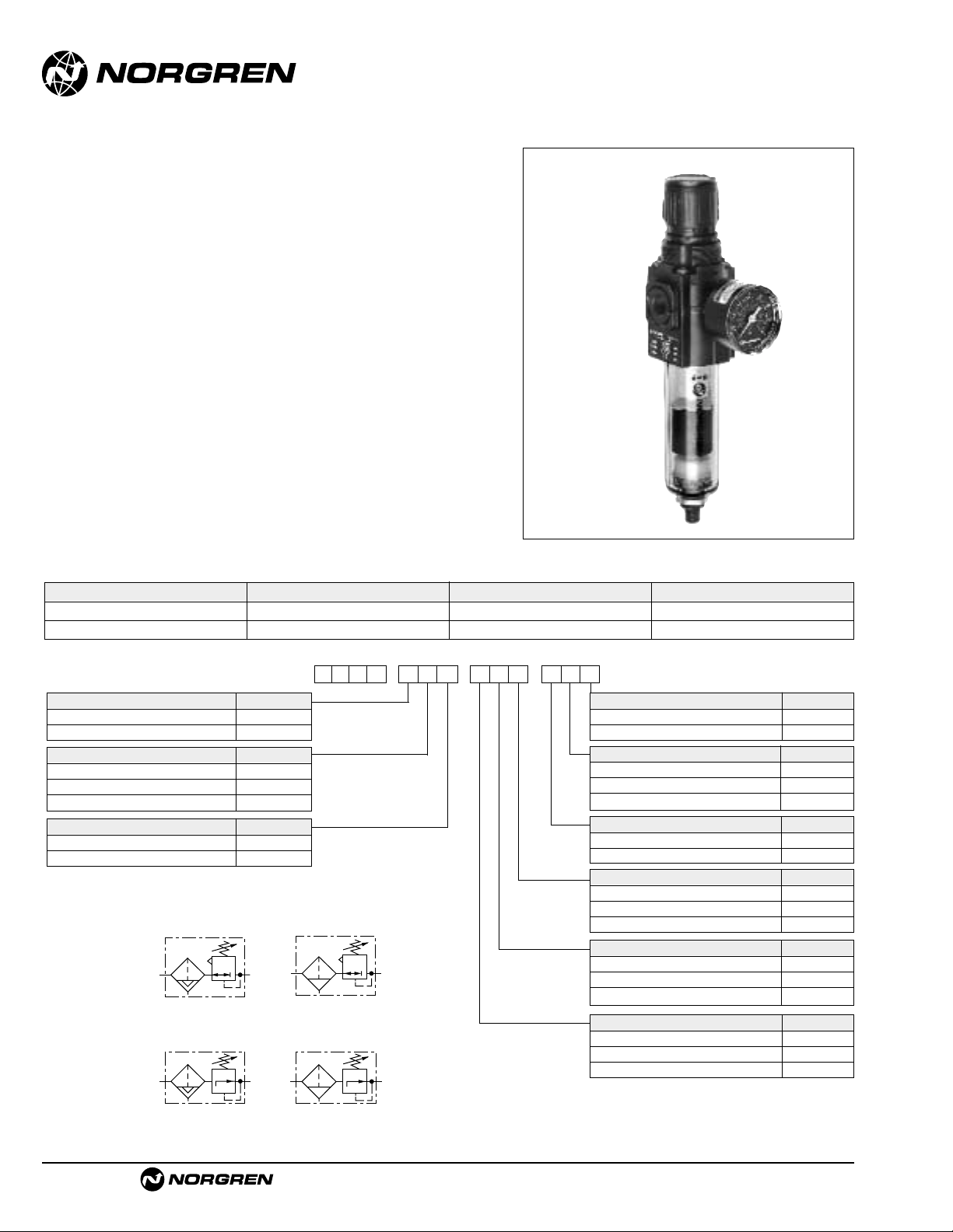
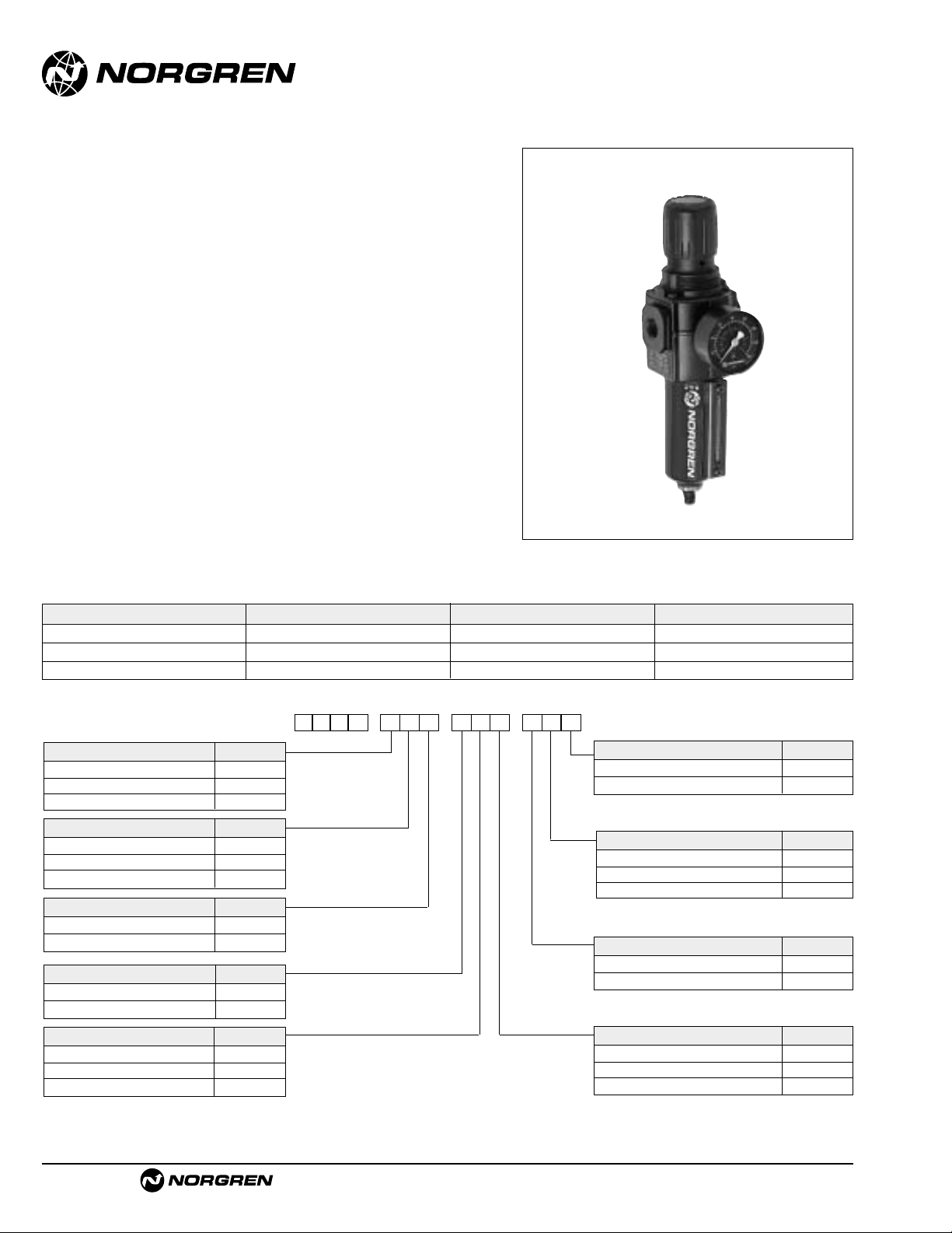
B07 Miniature General Purpose Filter/Regulator
1/8" and 1/4" ports . . . . . . . . . . . . . . . . . . . . . . . . . . . . . . . . . . .ALE-12-2
B72G Excelon General Purpose Filter/Regulator
1/4" and 3/8" ports . . . . . . . . . . . . . . . . . . . . . . . . . . . . . . . . . . .ALE-12-4
B73G Excelon General Purpose Filter/Regulator
1/4", 3/8", and 1/2" ports . . . . . . . . . . . . . . . . . . . . . . . . . . . . . .ALE-12-6
B74G Excelon General Purpose Filter/Regulator
3/8", 1/2", and 3/4" ports . . . . . . . . . . . . . . . . . . . . . . . . . . . . . .ALE-12-8
B64G Olympian Plus General Purpose Filter/Regulator
1/4", 3/8", 1/2", and 3/4" ports . . . . . . . . . . . . . . . . . . . . . . . . .ALE-12-10
B68G Olympian Plus General Purpose Filter/Regulator
3/4",1", 1-1/4", and 1-1/2" ports . . . . . . . . . . . . . . . . . . . . . . . .ALE-12-12
B39 Miniature Oil Removal Filter/Regulator
1/8" and 1/4" ports . . . . . . . . . . . . . . . . . . . . . . . . . . . . . . . . . .ALE-12-14
B38 Instrument Filter/Regulator Aluminum 1/4" ports . . . . . . . . .ALE-12-16
Filter/Regulator Overview and FAQ’s . . . . . . . . . . . . . . . . . . . . . .ALE-12-18
Filter/Regulators
Compressed air, general purpose,
and Instrument Filter/Regulators
1/8" to 1-1/2" port sizes
B07
B72G
B73G
B74G
B64G
B39
B38
B68G
Page 2

See Section ALE-24 for Accessories
Littleton, CO USA Phone 303-794-2611 www.norgren.com
B07
● Compact design
● Full flow gauge ports
● Low torque, non-rising adjusting knob
● Snap action knob locks pressure setting when
pushed in
● Standard relieving models allow reduction of outlet
pressure even when the system is dead-ended
● Protects air operated devices by removing liquid and
solids contaminants
● Screw-on bowl reduces maintenance time
● Can be disassembled without the use of tools or
removal from the air line
Series 07 General Purpose Filter/Regulator
1/8" and 1/4" Port S ize s
ALE-12-2
ISO Symbols
Automatic Drain
Relieving
Manual Drain
Relieving
Automatic Drain
Non Relieving
Manual Drain
Non Relieving
Alternative Models
-
★★★ ★★ ★
-
0★B 7
Threads Substitute
PTF A
ISO Rc taper B
ISO G parallel G
Drain Substitute
Automatic A
Manual M
Port Size Substitute
1/8" 1
1/4" 2
Element Substitute
5 µm 1
Bowl Relief Type Gauge Substitute
Transparent Relieving Without 01
Transparent Relieving With 02
Transparent Non-relieving Without 03
Transparent Non-relieving With 23
Metal Relieving Without 33
Metal Relieving With 34
Metal Non-relieving Without 35
Metal Non-relieving With 36
Outlet Pressure Adjustment Ranges* Substitute
1 to 10 psig (0.1 to 0.7 bar) A
5 to 50 psig (0.3 to 3.5 bar) E
5 to 100 psig (0.3 to 7 bar) K
5 to 125 psig (0.3 to 8.6 bar) L
Ordering Information. Models listed include PTF threads, transparent bowl, relieving diaphragm, gauge, automatic drain, 5 µm element, 5 to
100 psig (0.3 to 7 bar) outlet pressure adjustment range* .
Port Size Model Number Flow† scfm (dm3/s) Weight lbs (kg)
1/8" B07-102-A1KA 13 (6.2 dm3/s) 0.57 (0.26)
1/4" B07-202-A1KA 14 (6.5 dm3/s) 0.57 (0.26)
* Outlet pressure can be adjusted to pressures in excess of, and less than, those specified. Do not use these units to control pressures outside of the specified
ranges.
† Typical flow with 100 psig (7 bar) inlet pressure, 90 psig (6.3 bar) set pressure and a 15 psig (1 bar) droop from set.
Page 3
B07 Filter/Regulators
Littleton, CO USA Phone 303-794-2611 www.norgren.com
ALE-12-3
All Dimensions in Inches (mm)
n
n
** Minimum clearance to remove bowl
Panel mounting hole diameter 1.19" (30 mm)
Panel thickness:0.25" (6 mm)
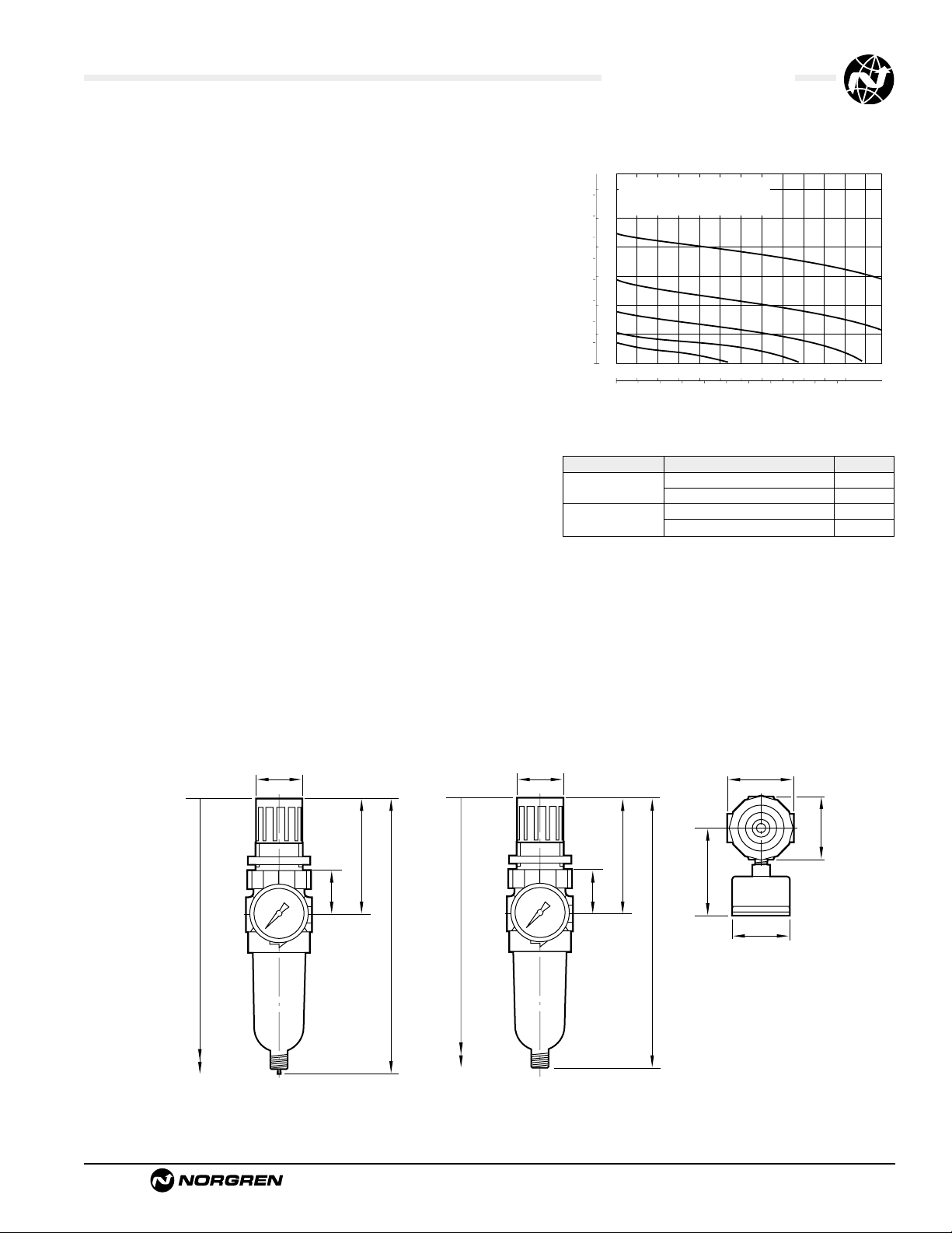
Typical Performance Characteristics
Service Kits
Item Type Part number
Service kit
Relieving models, 5 µm element 3820-12
Non relieving models, 5 µm element 3820-11
Replacement drains
Manual 773-03
Automatic 3654-02
Service kit includes slip ring, diaphragm, valve seat with o-ring,
valve, valve spring, element, element gasket, and bowl o-ring.
Technical Data
Fluid: Compressed air
Maximum pressure
Transparent bowl: 150 psig (10 bar)
Metal bowl: 250 psig (17 bar)
Operating temperature*
Transparent bowl: 30° to 125°F (-34° to 50°C)
Metal bowl: -30° to 150°F (-34° to 65°C)
* Air supply must be dry enough to avoid ice formation at temperatures below 35°F (2°C)
Particle removal: 5 µm or 40 µm filter element
Air quality: Within ISO 8573-1, Class 3 and Class 5 (par ticulates)
Typical flow at 100 psig (7 bar) inlet pressure, 90 psig (6.3 bar) set pressure and a
droop of 15 psig (1 bar) from set
1/8" Ports: 13 scfm (6.2 dm
3
/s) with 5 µm element
1/4" Ports: 14 scfm (6.5 dm3/s) with 5 µm element
Nominal bowl size: 1 fluid ounce (31 ml)
Gauge ports:
1/8" PTF with PTF main por ts
1/8" ISO Rc with ISO Rc main ports
1/8" ISO Rc with ISO G main ports
Drain connection:Will fit 1/8-27 and 1/8-28 pipe thread
Automatic drain operation:Spitter type drain operates momentarily when a rapid
change in air flow occurs or when the supply pressure is reduced.
Materials:
Body: Zinc
Bonnet: Acetal
Valve: Brass/nitrile
Valve seat: Acetal
Bowl
Transparent: Polycarbonate
Metal: Zinc
Element: Sintered polypropylene
Elastomers: Nitrile
PORT SIZE: 1/4"
psig
bar g
ELEMENT: 40 µm
8
INLET PRESSURE: 150 psig (10 bar g)
RANGE: 5 to 100 psig (0.3 to 7 bar)
100
6
80
60
4
OUTLET PRESSURE
40
2
20
0
0
0 4 8 12 16 20 24 scfm
0 2 4 6 8 10 dm3/s
FLOW CHARACTERISTICS
AIR FLOW
1.1 (28)
2.67 (68)
1.12 (28)
8.41 (214)**
Manual Drai
6.44 (164)
8.26 (210)**
1.1 (28)
Automatic Drai
1.63 (41)
1.50 (38)
2.67 (68)
2.13 (54)
1.12 (28)
1.50 (38)
6.29 (160)
Page 4
See Section ALE-24 for Accessories
Littleton, CO USA Phone 303-794-2611 www.norgren.com
B72G
● EXCELON design allows in-line or modular
installation
● High efficiency water and particle removal
● Quick release bayonet bowl
● Highly visible, prismatic liquid level indicator lens on
metal bowls
● Full flow gauge ports
● Balanced valve design for optimum pressure control
● Push to lock adjusting knob with tamper resistant
accessory
● Modular installations with EXCELON 72, 73, and 74
series can be made to suit particular applications
Excelon®72 Series Filter/Regulator
1/4" and 3/8" Port S ize s
ALE-12-4
ISO Symbols
Automatic and
Semi Automatic Drain
Relieving
Manual Drain
Relieving
Automatic and
Semi Automatic Drain
Non Relieving
Manual Drain
Non Relieving
Alternative Models
Ordering Information. Models listed include PTF threads, knob adjustment, automatic drain, transparent bo wl without guard,
40 µm element, relieving diaphragm, 5 to 150 psig (0.3 to 10 bar) outlet pressure adjustment rang*, with gauge.
† Typical flow with 150 psig (10 bar) inlet pressure, 90 psig (6.3 bar) set pressure and a 15 psig (1 bar) droop from set.
Port Size Model Flow†scfm (dm3/s) Weight lb (kg)
1/4" B72G-2AK-AL3-RMG 80 (38) 1.3 (0.59)
3/8" B72G-3AK-AL3-RMG 80 (38) 1.3 (0.59)
B 7 2-G
★ ★
-
★★ ★ ★
Port Size Substitute
1/4" 2
3/8" 3
Threads Substitute
PTF A
ISO Rc taper B
ISO G parallel G
Diaphragm Substitute
Relieving R
Non relieving N
Element Substitute
5 µm 1
25 µm 2
40 µm 3
Adjustment Substitute
Knob K
T-bar T
-
★★ ★
Drain Substitute
1/4 turn manual Q
Semi automatic S
Auto drain A
Gauge Substitute
With G
Without N
Outlet Pressure Adjustment Range* Substitute
5 to 30 psig (0.3 to 2 bar) C
5 to 60 psig (0.3 to 4 bar) F
5 to 150 psig (0.3 to 10 bar) M
* Outlet pressure can be adjusted to pressures in excess of, and less than, those
specified. Do not use these units to control pressures outside of the specified ranges.
Bowl Substitute
Long metal with liquid level indicator E
Long transparent without guard L
Long transparent with guard W
Page 5
B72G Filter/Regulators
Littleton, CO USA Phone 303-794-2611 www.norgren.com
ALE-12-5
All Dimensions in Inches (mm)
Technical Data
Fluid: Compressed air
Maximum pressure:Transparent bowl: 150 psig (10 bar)
Metal bowl: Manual or semi automatic drain: 250 psig (17 bar)
Automatic drain: 150 psig (10 bar)
Operating temperature*:Transparent bowl: -30° to 125°F (-34° to 50°C)
Metal bowl: -30° to 150°F (-34° to 65°C)
* Air supply must be dry enough to avoid ice formation at temperatures below 35°F (2°C ).
Particle removal: 5 µm, 25 µm or 40 µm. Within ISO 8573-1, Class 3 and Class 5
Typical flow at 150 psig (10 bar) inlet pressure, 90 psig (6.3 bar) set pressure and
a droop of 1 bar (15 psig) from set: 80 scfm (38 dm
3
/s)
Manual drain connection:Will fit 1/8-27 and 1/8-28 pipe thread
Semi automatic drain connection: Push on 5/16" (8 mm) ID tube
Semi automatic drain operating conditions (pressure operated):
Bowl pressure required to close drain: Greater than 1.5 psig (0.1 bar)
Bowl pressure required to open drain: Less than 1.5 psig (0.1 bar)
Minimum air flow required to close drain: 1 scfm (0.5 dm
3
/s)
Manual operation: Lift stem to drain bowl
Automatic drain connection:Will fit 1/8-27 and 1/8-28 pipe thread - Flexible tube
with 3/16" (5mm) minimum I.D.can be connected to the automatic drain. Drain
may fail to operate if the tube I.D. is less than 3/16" (5mm). Avoid restrictions in
the tube.
Automatic drain operating conditions (float operated):
Bowl pressure required to close drain: Greater than 5 psig (0.3 bar)
Bowl pressure required to open drain: Less than 3 psig (0.2 bar)
Minimum air flow required to close drain: 0.2 scfm (0.1 dm
3
/s)
Manual operation: Depress pin inside drain outlet to drain bowl
Gauge ports: 1/8"PTF with PTF main por ts
1/8" ISO Rc with ISO Rc main ports
1/8" ISO Rc with ISO G main ports
Nominal bowl size: Bowl: 2.2 fluid ounce (65 ml)
Materials
Body: Zinc
Bonnet: Acetal
Valve: Brass
Bowl
Transparent: Polycarbonate
Guard for transparent bowl:Zinc
Metal bowl liquid level indicator lens:
Transparent nylon
Element: Sintered polypropylene
Elastomers: Neoprene and nitrile
An automatic drain is a two-way valve, which will close when the system is
pressurized.The drain opens when the float rises due to accumulated liquid
and on depressurization.
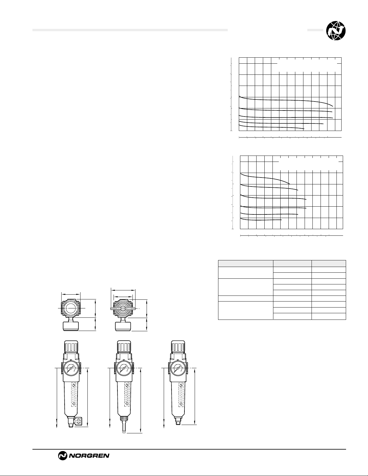
Typical Performance Characteristics
s
m
† Minimum clearance required to remove bowl.
Service Kits
Item Type Part Number
Service kit
Relieving 4383-500
Non relieving 4383-501
5 µm 5925-03
Replacement elements 25 µm 5925-01
40 µm 5925-02
Liquid level lens kit Prismatic 4380-030
1/4 turn manual 619-50
Replacement drains Semi automatic 5379-RK
Automatic 4000-50R
Service kit includes diaphragm assembly, valve assembly,
valve spring, louvre o-ring, bowl o-ring, drain seal.
Panel mounting hole diameter 1.57" (40 mm)
Panel thickness:0.16 (4 mm)
1.97 (50)
1.89 (48)
(35)
1.38
Knob Adjustment T-bar Adjustment
2.48 (63)
1.97 (50)
1.89 (48)
(35)
1.38
psig
bar g
12
150
9
120
90
6
OUTLET PRESSURE
60
3
30
0
0
0 10 20 30 40 50 60 scfm
0 5 10 15 20 25 dm3/s
psig
bar g
12
150
9
120
90
6
OUTLET PRESSURE
60
3
30
0
0
0 20 40 60 80 100 120 scf
0 10 20 30 40 50 dm3/
FLOW CHARACTERISTICS
PORT SIZE: 1/4" ELEMENT: 40 µm
INLET PRESSURE: 100 psig (7 bar g)
RANGE:
5 to 150 psig (0.3 to 10 bar)
AIR FLOW
FLOW CHARACTERISTICS
PORT SIZE: 1/4" ELEMENT: 40 µm
INLET PRESSURE: 150 psig (10 bar g)
RANGE:
5 to 150 psig (0.3 to 10 bar)
AIR FLOW
7.83 (199) †
5.83 (148)
Bowl with
1/4 Turn Manual Drain
9.84 (250) †
Bowl with
Semi auto Drain
7.48 (190)
7.52 (191) †
Bowl with
Automatic Drain
5.51 (140)
Page 6
See Section ALE-24 for Accessories
Littleton, CO USA Phone 303-794-2611 www.norgren.com
B73G
● Excelon design allows in-line or modular installation
● Quick release bayonet bowl
● Highly visible, prismatic liquid level indicator lens
● Full flow gauge ports
● Balanced valve design minimizes effect of variation
in the inlet pressure on the outlet pressure
● Modular installations with Excelon 72, 73, and 74
series can be made to suit particular applications
Excelon®73 Series Filter/Regulator
1/4",3/8",1/2" Por t Si zes
ALE-12-6
Ordering Information. Models listed include PTF threads, knob adjustment, automatic drain, metal bowl with liquid level indicator, 40 µm element,
relieving diaphragm, 5 to 150 psig (0.3 to 10 bar) outlet pressure adjustment range* with gauge.
† Typical flow with 150 psig (10 bar) inlet pressure, 90 psig (6.3 bar) set pressure and 15 psig (1 bar) droop from set.
Main Port Size Model Number Flow†scfm (dm3/s) Weight lb (kg)
1/4" B73G-2AK-AD3-RMG 78 (37) 1.76 (0.82)
3/8" B73G-3AK-AD3-RMG 123 (58) 1.76 (0.82)
1/2" B73G-4AK-AD3-RMG 123 (58) 1.76 (0.82)
Alternative Models
B 7 3-G
★ ★
-
★★ ★ ★
Threads Substitute
PTF A
ISO Rc taper B
ISO G parallel G
Adjustment Substitute
Knob K
T-bar T
Diaphragm Substitute
Relieving R
Non relieving N
Gauge Substitute
With G
Without N
Bowl Substitute
Metal with liquid level indicator D
Transparent with guard P
Transparent T
Element Substitute
5 µm 1
25 µm 2
40 µm 3
-
★★ ★
*Outlet pressure can be adjusted to pressures in excess of, and less than, those
specified.Do not use these units to control pressures outside of the specified ranges.
**Units with 250 psig (17 bar) outlet pressure range are available only with the
standard metal bowl.
Drain Substitute
Automatic A
Manual, 1/4 turn Q
Port Size Substitute
1/4" 2
3/8" 3
1/2" 4
Outlet Pressure Adjustment Range* Substitute
5 to 60 psig (0.3 to 4 bar) F
5 to 150 psig (0.3 to 10 bar) M
10 to 250 psig (0.7 to 17 bar)** S
Page 7

B73G Filter/Regulators
Littleton, CO USA Phone 303-794-2611 www.norgren.com
ALE-12-7
All Dimensions in Inches (mm)
Technical Data
Fluid: Compressed air
Maximum pressure
Transparent bowl: 150 psig (10 bar)
Metal bowl: 250 psig (17 bar)
Operating temperature*
Transparent bowl: -30° to 125°F (-34° to 50°C)
Metal bowl: -30° to 175°F (-34° to 80°C)
* Air supply must be dry enough to avoid ice formation at temperatures below 35°F (2°C).
Particle removal: 5 µm, 25 µm or 40 µm filter element
Air quality: Within ISO 8573-1, Class 3 and Class 5 (par ticulates)
Typical flow with 150 psig (10 bar) inlet pressure, 90 psig (6.3 bar) set pressure
and 15 psig (1 bar) droop from set: 123 scfm (58 dm
3
/s)
Manual drain connection:Will fit 1/8-27 and 1/8-28 pipe thread
Automatic drain connection:Will fit 1/8-27 and 1/8-28 pipe thread - Flexible tube
with 3/16" (5mm) minimum I.D.can be connected to the automatic drain. Drain
may fail to operate if the tube I.D. is less than 3/16" (5mm). Avoid restrictions in
the tube.
Automatic drain operating conditions (float operated):
Bowl pressure required to close drain: Greater than 5 psig (0.3 bar)
Bowl pressure required to open drain: Less than 3 psig (0.2 bar)
Minimum air flow required to close drain: 0.2 scfm (0.1 dm
3
/s)
Manual operation: Depress pin inside drain outlet to drain bowl
Nominal bowl size: 3.5 fluid ounce (0.1 liter)
Gauge ports:
1⁄4" PTF with PTF main ports
Rc1/4 with ISO Rc main ports
Rc1/8 with ISO G main ports
Materials
Body: Aluminum
Bonnet: Aluminum or Zinc
Valve: Brass
Bowl:
Transparent: Polycarbonate
Transparent with guard: Polycarbonate, steel guard
Metal: Aluminum
Metal bowl liquid level indicator lens:Transparent nylon
Element: Sintered polypropylene
Elastomers: Neoprene and nitrile
An automatic drain is a two-way valve, which will close when the system is
pressurized.The drain opens when the float rises due to accumulated liquid and
on depressurization.
Automatic Drain, Non-Relieving
Manual Drain, Non-Relieving
ISO Symbols
Automatic Drain, Relieving
Manual Drain, Relieving
Typical Performance Characteristics
** Minimum clearance to remove bowl.
Service kit includes diaphragm assembly, valve assembly, valve
spring, bowl o-ring, and automatic drain seal.
Service Kits
Item Type Part Number
Service kit Relieving 4383-600
Non-relieving 4383-601
Replacement elements
5 µm 4438-01
25 µm 4438-02
40 µm 4438-03
Liquid level lens kit Prismatic 4380-020
Replacement drains
Automatic 4000-51R
Manual quarter turn 619-50
Panel mounting hole diameter 1.89" (48 mm)
Panel thickness:0.25 (6 mm)
1.22 (31)
2.68 (68)
2.00 (50)
2.45 (62)
2.20 (56)3.80 (96)5.80 (147)
bar
psig
8
100
6
80
60
4
OUTLET PRESSURE
40
2
20
0
0
0 40 80 120 160 200 scfm
0 20 40 60 80 100 dm3/s
PORT SIZE: 3/8"
bar
ELEMENT: 40 µm
psig
INLET PRESSURE: 100 psig (7 bar)
RANGE: 5 to 150 psig (0.3 to 10 bar)
100
6
80
60
4
OUTLET PRESSURE
40
2
20
0
0
0 20 40 60 80 100 scfm
01020304050dm
FLOW CHARACTERISTICS
INLET PRESSURE: 150 psig (10 bar)
RANGE: 5 to 150 psig (0.3 to 10 bar)
AIR FLOW
FLOW CHARACTERISTICS
AIR FLOW
PORT SIZE: 3/8"
ELEMENT: 40 µm
3
/s
0.45 (12)
(31)
1.22
8.15 (207)**
Automatic Drain
4.04 (103)6.15 (156)
8.50 (216)**
1/4 Turn Manual Drain
Page 8

See Section ALE-24 for Accessories
Littleton, CO USA Phone 303-794-2611 www.norgren.com
B74G
● EXCELON design allows in-line or modular
installation
● Quick release bayonet bowl
● Highly visible, prismatic liquid level indicator lens
● Full flow gauge ports
● Balanced valve design minimizes effect of variation
in the inlet pressure on the outlet pressure
● Modular installations with EXCELON 72, 73, and 74
series can be made to suit particular applications
Excelon®74 Series Filter/Regulator
3/8",1/2",3/4" Por t Si zes
ALE-12-8
Ordering Information. Models listed include PTF threads, knob adjustment, automatic drain, metal bowl with liquid level indicator, 40 µm element,
relieving diaphragm, 5 to 150 psig (0.3 to 10 bar) outlet pressure adjustment range*, with gauge.
† Typical flow with 150 psig (10 bar) inlet pressure, 90 psig (6.3 bar) set pressure and a 15 psig (1 bar) droop from set.
Main Port Size Model Number Flow†scfm (dm3/s) Weight lb (kg)
3/8" B74G-3AK-AD3-RMG 163 (77) 2.62 (1.19)
1/2" B74G-4AK-AD3-RMG 212 (100) 2.59 (1.17)
3/4" B74G-6AK-AD3-RMG 212 (100) 2.55 (1.16)
Alternative Models
B 7 4-G
★ ★
-
★★ ★ ★
Threads Substitute
PTF A
ISO Rc taper B
ISO G parallel G
Adjustment Substitute
Knob K
T-bar T
Diaphragm Substitute
Relieving R
Non relieving N
Gauge Substitute
With G
Without N
Outlet Pressure
Adjustment Range* Substitute
5 to 60 psig (0.3 to 4 bar) F
5 to 150 psig(0.3 to 10 bar ) M
10 to 250 psig (0.7 to 17 bar )** S
Bowl Substitute
Metal with liquid level indicator D
Transparent with guard P
Element Substitute
5 µm 1
25 µm 2
40 µm 3
-
★★ ★
* Outlet pressure can be adjusted to pressures in excess of, and less than, those
specified. Do not use these units to control pressures outside of the specified
ranges.
** Units with 250 psig (17 bar) outlet pressure range are available only with the Tbar adjustment; therefore substitute T at the 7th digit and S at the 12th position.
Drain Substitute
Automatic A
Manual, 1/4 turn Q
Port Size Substitute
3/8" 3
1/2" 4
3/4" 6
Page 9

B74G Filter/Regulators
Littleton, CO USA Phone 303-794-2611 www.norgren.com
ALE-12-9
All Dimensions in Inches (mm)
Technical Data
Fluid: Compressed air
Maximum pressure:
Transparent bowl: 150 psig (10 bar)
Metal bowl: 250 psig (17 bar)
Operating temperature*:
Transparent bowl: -30° to 125°F (-34° to 50°C)
Metal bowl: -30° to 175°F (-34° to 80°C)
* Air supply must be dry enough to avoid ice formation at temperatures below 35°F (2°C).
Particle removal: 5, 25 or 40 µm filter element
Air quality: Within ISO 8573-1, Class 3 and Class 5 (par ticulates)
Typical flow with 150 psig (10 bar) inlet pressure, 6.3 (90 psig) set pressure and a
droop of 15 psig (1 bar) from set: 212 scfm (100 dm
3
/s)
Manual drain connection:Will fit 1/8-27 and 1/8-28 pipe thread
Automatic drain connection:Will fit 1/8-27 and 1/8-28 pipe thread
Automatic drain operating conditions (float operated):
Bowl pressure required to close drain: Greater than 5 psig (0.3 bar)
Bowl pressure required to open drain: Less than 3 psig (0.2 bar)
Minimum air flow required to close drain: 2 scfm (1 dm
3
/s)
Manual operation: Depress pin inside drain outlet to drain bowl
Nominal bowl size: 7 fluid ounce(0.2 liter )
Gauge ports:
1⁄4" PTF with PTF main ports
Rc1⁄4 with ISO Rc main ports
Rc1⁄8 with ISO G main ports
Materials
Body: Aluminum
Bonnet: Aluminum
Valve: Brass
Bowl
Transparent: Polycarbonate with steel bowl guard
Metal: Aluminum
Metal bowl liquid level indicator lens:Transparent nylon
Element: Sintered plastic
Elastomers: Neoprene and Nitrile
An automatic drain is a two-way valve, which will close when the system is
pressurized.The drain opens when the float rises due to accumulated liquid
and on depressurization.
Automatic Drain, Non Relieving Manual Drain, Non Relieving
ISO Symbols
Automatic Drain, Relieving
Manual Drain, Relieving
Typical Performance Characteristics
Panel mounting hole diameter: 2.06" (52 mm)
Panel thickness:0.06" to 0.25" (2 to 6 mm)
Service kit includes diaphragm assembly, valve assembly, valve
spring, louvre o-ring, bowl o-ring, drain seal.
Service Kits
Item Type Part Number
Service kit Relieving 4383-700
Non relieving 4383-701
Replacement elements
5 µm 4338-04
25 µm 4338-07
40 µm 4338-05
Liquid level lens kit Prismatic 4380-050
Replacement drains
Automatic (1/8 NPT outlet) 3000-10
Manual quarter turn 619-50
** Minimum clearance to remove bowl.
3.15 (80)
psig
bar g
100
6
80
60
4
OUTLET PRESSURE
40
2
20
0
0
0 40 80 120 160 200 scfm
0 20 40 60 80 100 dm3/s
psig
bar g
100
6
80
60
4
OUTLET PRESSURE
40
2
20
0
0
0 40 80 120 160 200 scfm
0 20 40 60 80 100 dm3/s
FLOW CHARACTERISTICS
PORT SIZE: 1/2",
INLET PRESSURE: 150 psig (10 bar g)
RANGE: 5 to 150 psig (0.3 to 10 bar)
AIR FLOW
FLOW CHARACTERISTICS
PORT SIZE: 1/2",
INLET PRESSURE: 100 psig (7 bar g)
RANGE: 5 to 150 psig (0.3 to 10 bar)
AIR FLOW
ELEMENT: 40 µm
ELEMENT: 40 µm
2.89 (74)2.20 (56)
1.45 (37)
2.00 (50)
9.06 (230)**
Automatic Drain
1.24 (31)
1.69 (43)
4.98 (127)
5.95 (151)
6.35 (161)
9.69 (246)**
6.95 (177)
Manual Drain
Page 10

See Section ALE-24 for Accessories
Littleton, CO USA Phone 303-794-2611 www.norgren.com
B64G
● Olympian Plus plug in design
● High Efficiency water and particle removal
● Quick release bayonet bowl
● High visibility prismatic sight glass
● Push to lock adjusting knob with tamper resistant
option
Olympian Plus Filter/Regulator
1/4",3/8", 1/2",3/4" Port Sizes
ALE-12-10
Ordering Information.
Models listed include PTF threads, knob adjustment, automatic drain, metal bowl, 40 µm element, relieving diaphragm, 5 to 150
psig (0.3 to 10 bar) outlet pressure adjustment range* with gauge.
† Typical flow with 150 psig (10 bar) inlet pressure, 90 psig (6.3 bar) set pressure and a 15 psig (1 bar) droop from set.
Port Size Model Flow†scfm (dm3/s) Weight lb (kg)
1/4" B64G-2AK-AD3-RMG 64 (30) 3.80 (1.71)
3/8" B64G-3AK-AD3-RMG 161 (76) 3.76 (1.69)
1/2" B64G-4AK-AD3-RMG 225 (106) 3.69 (1.66)
3/4" B64G-6AK-AD3-RMG 225 (106) 4.49 (2.02)
Alternative Models
B 6 4-G
★ ★
-
★★ ★ ★
Port Size Substitute
1/4" 2
3/8" 3
1/2" 4
3/4" 6
No Yoke N
Threads Substitute
PTF A
ISO Rc taper B
ISO G parallel G
Diaphragm Substitute
Relieving R
Non relieving N
Element Substitute
5 µm 1
25 µm 2
40 µm 3
Adjustment Substitute
Knob K
T-bar T
Bowl Substitute
Metal with liquid level indicator D
Guarded Transparent P
-
★★ ★
Drain Substitute
1/4 turn manual Q
Automatic A
Gauge Substitute
With G
Without N
Outlet Pressure Adjustment Range* Substitute
5 to 60 psig (0.3 to 4 bar) F
5 to 150 psig (0.3 to 10 bar) M
10 to 250 psig (0.7 to 17 bar) S**
* Outlet pressure can be adjusted to pressures in excess of, and less than, those
specified. Do not use these units to control pressures outside of the specified ranges.
** Units with 250 psig (17 bar) adjustment range are available only with the T-bar
adjustment; therefore substitute T at the 7th digit and S at the 12th position.
Page 11

B64G Filter/Regulators
Littleton, CO USA Phone 303-794-2611 www.norgren.com
ALE-12-11
All Dimensions in Inches (mm)
ISO Symbols
Automatic Drain
Relieving
Manual Drain
Relieving
Automatic Drain
Non Relieving
Manual Drain
Non Relieving
Technical Data
Fluid: Compressed air
Maximum pressure
Guarded transparent bowl: 150 psig (10 bar)
Metal bowl: 250 psig (17 bar)
Operating temperature*
Guarded transparent bowl: -30° to 125°F (-34° to 50°C)
Metal bowl: -30° to 175°F (-34° to 80°C)
* Air supply must be dry enough to avoid ice formation at temperatures below 35°F (2°C).
Particle removal: 5, 25 or 40 µm. Within ISO 8573-1, Class 3 and Class 5
Typical flow at 90 psig (6.3 bar) inlet pressure:
225 scfm (106 dm
3
/s)
Manual drain connection:Will fit 1/8-27 and 1/8-28 pipe thread
Automatic drain connection:Will fit 1/8-27 and 1/8-28 pipe thread
Automatic drain operating conditions:
Minimum pressure: 10 psig (0.7 bar).
Drain opens when bowl pressure drops below 3 psig (0.2 bar).
Minimum air flow: 2 scfm (1 dm
3
/s) required to close drain.
Gauge Ports:
1/8" PTF with PTF main ports
1/8" ISO Rc with ISO Rc main por ts
1/8" ISO Rc with ISO G main por ts
Nominal bowl size:
7 fluid ounce (0.2 liter)
Materials:
Body: Zinc
Bonnet: Aluminum
Valve: Brass
Yoke: Zinc
Metal bowl: Aluminum
Standard metal bowl prismatic liquid level indicator lens:Grilamid
Optional metal bowl sight glass: Pyrex
Optional transparent bowl: Polycarbonate
Element: Sintered plastic
Elastomers: Synthetic rubber
An automatic drain is a two-way valve, which will close when the system is
pressurized.The drain opens when the float rises due to accumulated liquid
and on depressurization.
Typical Performance Characteristics
Service Kits
Item Type Part Number
Service kit
Relieving 4383-200
Non relieving 4383-201
5 µm 4338-01
Replacement elements 25 µm 4338-99
40 µm 4338-02
Replacement Sight Glass
Prismatic (standard) 4380-040
Pyrex 4380-041
Replacement Drains
Automatic 3000-10
Manual 684-84
Service kit includes diaphragm assembly, valve assembly,
valve spring, louver o-ring, bowl o-ring, drain seal.
** 4.13 (105) for 1/4", 3/8", and 1/2" ported yokes.
6.18" (157) for 3/4" ported yokes.
† Add 1.46 (37) for units with T-handle adjustment.
†† Minimum clearance required to remove unit.
Add 1.46 (37) for units with T-handle adjustment.
4.92 (125)†
11.30 (287)†
11.99 (303)††
12.60 (320)††
11.97 (304)†
4.13 (105)**
1.46
(37)
2.91 (74)
psig
bar g
8
100
6
80
60
4
OUTLET PRESSURE
40
2
20
0
0
0 40 80 120 160 200 240 scfm
0 20 40 60 80 100 dm3/s
FLOW CHARACTERISTICS
PORT SIZE: 1/2" 40 µm ELEMENT
INLET PRESSURE: 150 psig (10 bar)
RANGE: 5 to 150 psig (0.3 to 10 bar)
AIR FLOW
Page 12

Littleton, CO USA Phone 303-794-2611 www.norgren.com
B68E/G
● Olympian Plus plug in system
● Effective liquid removal and positive solid particle
filtration
● Large filter element area provides minimum pressure
drop
● High flow unit with large valve and diaphragm
● Push to lock adjusting knob with tamper resistant
option
● Excellent flow and regulation characteristics
Olympian Plus Filter/Regulator
3/4",1", 1-1/4", 1-1/2" Port Sizes
ALE-12-12
Ordering Information.
Models listed include a 1 quart w/long element, yoke with PTF threads, knob adjustment, automatic drain, 40 µm element, relieving
diaphragm, and a 5 to 120 psig (0.4 to 8 bar) outlet pressure adjustment range*.A gauge is not included.
Port Size Model Flow**scfm (dm3/s) Weight lb (kg)
3/4 B68E-6AK-AU3-RLN 509 (240) 6.47 (2.94)
1 B68E-8AK-AU3-RLN 509 (240) 6.20 (2.82)
1-1/4 B68E-AAK-AU3-RLN 509 (240) 6.42 (2.92)
1-1/2 B68E-BAK-AU3-RLN 509 (240) 6.07 (2.76)
Alternative Models
B 6 8-E
★ ★
-
★★ ★ ★
Diaphragm Substitute
Relieving R
Non relieving N
Element Substitute
5 µm 1
25 µm 2
40 µm 3
Adjustment Substitute
Knob K
T-bar T
Bowl Substitute
1 quart (1 liter) without liquid level
indicator C††
1 pint (0.5 liter) without liquid level
indicator M†
1 pint (0.5 liter) with liquid level
indicator R†
1 quart (1 liter) with liquid level
indicator U
††
-
★★ ★
Gauge Substitute
With G
Without N
Outlet Pressure Adjustment Range* Substitute
0 to 60 psig(0 to 4 bar) F
5 to 120 psig (0.4 to 8 bar) L
10 to 250 psig (0.7 to 17 bar) S***
* Outlet pressure can be adjusted to pressures in excess of, and less than, those specified. Do not use these units to control pressures outside of the specified ranges.
** Typical flow with 150 psig (10 bar) inlet pressure, 90 psig (6.3 bar) set pressure and a 15 psig (1 bar) droop from set.
*** Units with 250 psig (17 bar) adjustment range are available only with the T-bar adjustment; therefore substitute T at the 7th digit and S at the 12th position.
† Only available with B68G.
†† Only availab le with B68EE
Port Size Substitute
3/4" 6
1" 8
1-1/4" A
1-1/2" B
No Yoke N
Threads Substitute
PTF A
ISO Rc taper B
ISO G parallel G
No Yoke (N in 5th position) N
Rc threaded gauge ports
No Yoke (N in 5th position) A
PTF threaded gauge ports
Bowl/Element Type Substitute
1 quart (1 liter) bowl w/long element E
1 pint (0.5 liter) bowl w/short element G
Drain Substitute
Automatic A
No drain (Closed bowl) E
Manual M
Manual, 1/4 turn Q
Page 13

1 Pint US
(0.5 Liter) Bowl
† Add 1.46" (37 mm) for unit with T-bar adjustment. * Dimension also applies to closed bottom bowl.
** For 1-1/4" and 1-1/2" ported yokes, add 0.39" (10 mm). ¶ Minimum clearance required to remove bowl.
Manual Drain
1/4 Turn Manual Drain
1 Quart US
(1 Liter) Bowl
1/4 Turn Manual Drain
13.5 (343) ¶ *
7.5 (190)*
5.32 (135) †
2.40
(61)
Automatic Drain
.
13.8 (350) ¶
7.8 (197)
Manual Drain
14.2 (361) ¶
8.2 (208)
10.6 (269)
18.2 (463) ¶
10.2 (258)
17.8 (452) ¶
17.5 (445) ¶ *
Automatic Drain
.
9.9 (251)*
5.32 (135) †
2.40
(61)
7.48 (190)**
2.13
(54)
B68E/G Filter/Regulators
Littleton, CO USA Phone 303-794-2611 www.norgren.com
ALE-12-13
All Dimensions in Inches (mm)
Technical Data
Fluid: Compressed air
Maximum pressure: 250 psig (17 bar)
Operating temperature*: 0° to +175°F (-20° to +80°C)
* Air supply must be dry enough to avoid ice formation at temperatures below +35°F (+2°C).
Partical removal: 5, 25 or 40 µm
Air quality: Within ISO 8573-1, Class 3 and Class 5 (particulates)
Typical flow at 150 psig (10 bar) inlet pressure, 90 psig (6.3 bar) set pressure and
a droop of 15 psig (1 bar) from set: 509 scfm (240 dm3/s)
1/4 turn manual drain connection: 1/8" pipe thread
Automatic drain connection: 1/8" pipe thread
Automatic drain operating conditions (float operated):
Bowl pressure required to close drain: Greater than 5 psig (0.3 bar)
Bowl pressure required to open drain: Less than 3 psig (0.2 bar)
Minimum air flow required to close drain: 2 scfm (1 dm3/s)
Manual operation: Depress pin inside drain outlet to drain bowl
Nominal bowl size:
1 pint U.S.(0.5 liter)
1 quart U.S. (1 liter)
Gauge ports:
1/8 PTF with PTF yoke ports
Rc1/8 with ISO Rc yoke ports
Rc1/8 with ISO G yoke ports
Materials:
Body: Aluminum
Yoke: Aluminum
Bonnet: Aluminum
Adjusting knob: Acetal resin
Optional T-bar adjusting screw: Steel
Valve: Aluminum
Bowl: Aluminum
Sight glass: Pyrex
Element: Sintered bronze or polypropylene
Elastomers: Synthetic rubber
An automatic drain is a two-way valve, which will close when the system is
pressurized.The drain opens when the float rises due to accumulated liquid
and on depressurization.
Typical Performance Characteristics
Service Kits
Item Type Part Number
Service kit
Relieving 4383-300
Non relieving 4383-301
5 µm (1 pint bowl) 5576-97
25 µm (1 pint bowl) 5576-98
Replacement 40 µm (1 pint bowl) 5576-99
elements 5 µm (1 quart bowl) 5311-01
25 µm (1 quart bowl) 5511-02
40 µm (1 quart bowl) 5511-03
Replacement 1 pint bowl 4380-060
sight glass kit 1 quart bowl 4380-061
Replacement Automatic (G 1/8 outlet) 3000-97
Drains Automatic (1/8 NPT outlet) 3000-10
Manual 684-84
Manual quarter turn 619-50
Service kit includes, valve spring, slip ring, valve assembly,
diaphragm assembly and necessary seals and ‘o’rings.
Automatic Drain
Relieving
Manual Drain
Relieving
Automatic Drain
Non Relieving
Manual Drain
Non Relieving
See Section ALE-24 for Accessories
psig
bar g
120
8
100
6
80
60
4
OUTLET PRESSURE
40
2
20
0
0
0 80 160 240 320 400 480 scfm
0 40 80 120 160 200 dm3/s
FLOW CHARACTERISTICS
PORT SIZE: 1", ELEMENT: 40 µm
INLET PRESSURE: 150 psig (10 bar)
RANGE: 5 to 120 psig (0.4 to 8 bar)
AIR FLOW
Page 14

See Section ALE-24 for Accessories
ALE-12-14
Littleton, CO USA Phone 303-794-2611 www.norgren.com
B39
● Compact design
● High efficiency oil and particle removal
● Low torque, non-rising adjusting knob
● Snap action knob locks pressure setting when
pushed in
● Standard relieving models allow reduction of outlet
pressure even when the system is dead-ended
Miniature Series 07 Oil Removal
Filter/Regulator 1/8" and 1/4" Port S ize s
ISO Symbols
Automatic Drain
Relieving
Manual Drain
Relieving
Automatic Drain
Non Relieving
Manual Drain
Non Relieving
Ordering Information. Models listed include PTF threads, transparent bowl, relieving diaphragm, gauge, automatic drain, 5 to 100 psig (0.3 to 7
bar) outlet pressure adjustment range* .
Port Size Model Number Flow† scfm (dm3/s) Weight lbs (kg)
1/8" B39-102-A0KA 4.0 (1.9) 0.57 (0.26)
1/4" B39-202-A0KA 4.0 (1.9) 0.57 (0.26)
† Maximum flow with 90 psig (6.3 bar) inlet pressure to maintain stated oil removal performance.
Alternative Models
-
★★★ ★★ ★
-
3★B 9
Threads Substitute
PTF A
ISO Rc taper B
ISO G parallel G
Drain Substitute
Automatic A
Manual M
Element Substitute
Coalescing 0
Bowl Relief T ype Gauge Substitute
Transparent Relieving Without 01
Transparent Relieving With 02
Transparent Non-relieving Without 03
Transparent Non-relieving With 23
Metal Relieving Without 33
Metal Relieving With 34
Metal Non-relieving Without 35
Metal Non-relieving With 36
Outlet Pressure Adjustment Ranges* Substitute
1 to 10 psig (0.1 to 0.7 bar) A
5 to 50 psig (0.3 to 3.5 bar) E
5 to 100 psig (0.3 to 7 bar) K
5 to 125 psig (0.3 to 8.6 bar) L
* Do not use these units to control pressures outside of the specified ranges.
Port Size Substitute
1/8" 1
1/4" 2
Page 15

ALE-12-15
All Dimensions in Inches (mm)
B39 Oil Removal Filter/Regulator
Littleton, CO USA Phone 303-794-2611 www.norgren.com
Technical Data
Fluid: Compressed air
Maximum pressure
Transparent bowl: 150 psig (10 bar)
Metal bowl: 250 psig (17 bar)
Operating temperature*
Transparent bowl: -30° to 125°F (-34° to 50°C)
Metal bowl: -30° to 150°F (-34° to 65°C)
* Air supply must be dry enough to avoid ice formation at temperatures below 35°F (2°C)
Particle removal: Down to 0.01 µm
Air quality: Within ISO 8573-1, Class 1 (par ticulates) and Class 2 (oil content)
Maximum remaining oil content in outlet air: 0.01 ppm at 70°F (21°C) with an inlet
concentration of 17 ppm.
Maximum flow with 90 psig (6.3 bar) inlet pressure
†
:
4.0 scfm (1.9 dm
3
/s)
† Maximum flow to maintain stated oil removal performance.
Nominal bowl size: 1 fluid ounce (31 ml)
Gauge ports:
1/8" PTF with PTF main por ts
1/8" ISO Rc with ISO Rc main ports
1/8" ISO Rc with ISO G main ports
Drain connection:Will fit 1/8-27 and 1/8-28 pipe thread
Automatic drain operation:Spitter type drain operates momentarily when a rapid
change in air flow occurs or when the supply pressure is reduced.
Materials
Body: Zinc
Bonnet: Acetal
Valve: Brass/nitrile
Valve seat: Acetal
Bowl
Transparent: Polycarbonate
Metal: Zinc
Element: Synthetic fiber and polyurethane foam
Elastomers: Nitrile
Typical Performance Characteristics
n
n
2.13 (54)
1.63 (41)
1.50 (38)
1.50 (38)
8.41 (214)**
1.12 (28)
2.67 (68)
6.44 (164)
1.1 (28)
8.26 (210)**
1.12 (28)
2.67 (68)
6.29 (160)
1.1 (28)
Panel mounting hole diameter: 1.19" (30 mm)
Maximum panel thickness: 0.25" (6 mm)
** Minimum clearance to remove bowl
Service Kits
Item Type Part number
Service kit
Relieving models 3407-66
Non relieving models 3407-65
Element 4141-10
Replacement drains
Manual 773-03
Automatic 3654-02
Relieving and non-relieving service kits include slip ring,
diaphragm, valve seat with o-ring, valve, and valve spring. Element
kit contains element, element gasket, and bowl o-ring.
FLOW CHARACTERISTICS
PORT SIZE: 1/8
psig
bar g
INLET PRESSURE: 150 psig (10 bar g)
8
RANGE: 5 to 100 psig (0.3 to 7 bar)
100
6
80
60
4
OUTLET PRESSURE
40
2
20
0
0
0 1 2 3 4 5 6 scfm
0 0.5 1 1.5 2 2.5 dm3/s
"
AIR FLOW
Manual Drai
Automatic Drai
Page 16

See Section ALE-24 for Accessories
Littleton, CO USA Phone 303-794-2611 www.norgren.com
B38
● Compact instrument units with high performance
● Stable regulation and temperature compensation
● Excellent flow and regulation characteristics
Instrument Filter/Regulator
Aluminum Model 1/4" PTF
ALE-12-16
ISO Symbols
Automatic Drain, Relieving
Automatic Drain,
Non Relieving
Manual Drain, Relieving
Manual Drain,
Non Relieving
Alternative Models
Port Size Substitute
1/4” PTF 2
Type Substitute
Aluminum 0
Diaphragm Substitute
Relieving 0
Non relieving 1
Relieving, bracket and nut 2
Non relieving, bracket and nut 3
Relieving with nut 4
Non relieving with nut 5
Threads Substitute
PTF A
ISO Rc taper B
ISO G parallel D
API.LP.INT K
Port Size Model Number Flow†scfm (dm3/s) Weight lbs (kg)
1/4" PTF B38-200-B2CA 17 (8) 1.18 (0.53)
Ordering Information. Models listed are relieving type with PTF threads, manual drain, 25 µm element, screw adjustment, 0.6 to 30 psig
(0.04 to 2 bar) outlet pressure adjustment range and without gauge.
Outlet Pressure Adjustment Ranges* Substitute
0.6 to 30 psig (0.04 to 2 bar) C
1 to 60 psig (0.07 to 4 bar) F
3.6 to 100 psig (0.25 to 7 bar) K
Element Substitute
5 µm 1
25 µm 2
83B
★ ★ ★ ★ ★ ★ ★
--
Drain Substitute
Manual B
* Outlet pressure can be adjusted to pressures in excess of, and less than, those
specified. Do not use these units to control pressures outside of the specified ranges.
† Typical flow 100 psig (7bar) inlet pressure, 15 psig (1 bar) set pressure, and a droop of 1 psig (0.05 bar) from set.
Page 17

B38 Instrument Filter/Regulators
Littleton, CO USA Phone 303-794-2611 www.norgren.com
ALE-12-17
All Dimensions in Inches (mm)
Technical Data
Fluid: Compressed air
Maximum pressure
Manual drain: 300 psig (20 bar)
Operating temperature: -40° to 175°F (-40° to 80°C) *
* Air supply must be dry enough to avoid ice formation at temperatures below 35°F (2°C).
Particle removal: 5 µm or 25 µm filter element
Air quality: Within ISO 8573-1, Class 3 and Class 5 (par ticulates)
Typical flow with 100 psig (7 bar) inlet pressure, 15 psig (1 bar) set pressure and a
droop of 1 psig (0.05 bar) from set:
17 scfm (8 dm
3
/s)
Manual Drain
Nominal bowl size:
2.4 fluid ounce (70 ml)
Gauge ports:
1/4" PTF
Materials
Body: Aluminum
Bonnet: Aluminum
Bowl: Aluminum
Adjusting screw: Steel
Elements
25 µm: High density polyethylene
5 µm: Ceramic pyrolith
Elastomeric materials: Synthetic rubber
Typical Performance Characteristics
INLET PRESSURE - 100 psig (7 bar g)
FLOW CHARACTERISTICS -
PORT SIZE: 1/4"
0 2 4 6 8 10 dm3/s
AIR FLOW
0 4 8 12 16 20 24 scfm
OUTLET PRESSURE
4
3
2
1
0
bar g
50
40
30
20
10
0
psig
** Minimum clearance required to remove bowl.
Panel mounting hole diameter: 1.65" (42 mm)
Maximum panel thickness: 0.24" (6 mm)
Service Kits
Item Type Part number
30 psig (2 bar) range Relieving R38-100R
Non relieving R38-100NR
60 and 100 psig Relieving R38-101R
(4 bar and 7 bar) range Non relieving R38-101NR
5 micron element B38-100A (5)
25 micron element B38-100A (25)
Service kits includes diaphragm assembly, o-ring, valve, valve
spring and 8 pan head screws.
2.52 (64)
1.26 (32)
REGULATION CHARACTERISTICS - PORT SIZE: 1/4"
MAXIMUM RECOMMENDED
psig
FLOW THROUGH 1/4
bar g
10%
60
100%
4
200%
50
3
40
30
2
OUTLET PRESSURE
20
1
10
"
PIPE
100% FLOW
scfm dm3/s
7.9 3.7
5 2.4
3.6 1.7
2.5 1.2
2.52 (64)
9.17 (233)**
0.51 (13)
1/8" PTF
2.09 (53)
3.11 (79)
2.95 (75)
5.71 (194)
0
0
0 20 40 60 80 100 psig
0 2 4 6 8 bar g
INLET PRESSURE
Page 18

Filter/Regulator Overview and FAQ’s
Littleton, CO USA Phone 303-794-2611 www.norgren.com
ALE-12-18
GENERAL PURPOSE FILTER/REGULATOR
1.1 GENERAL OVERVIEW
Filter/regulators combine the features of a filter and
regulator with a single compact body.
Air passes through the filter section first
removing water and particle contaminants, and is
then regulated by the top regulator section.
See individual filter and regulator sections
for details.
1.2 PERFORMANCE
CHARACTERISTICS
The regulator section of the filter/regulator
determines the flow and regulation characteristics of
the unit.
Flow is therefore measured in terms of
pressure droop from set pressure (see regulators)
and not flow versus pressure drop as in a filter.
Regulation characteristics are determined
in the same way as regulators.
1.3 SPECIALS
1.3.1 Can we do a Coalescing Filter/Regulator?
Yes. We have a B39 unit in the 07 Series. Other
sizes could be considered for volume customers.
1.3.2 Can we do special materials?
Units are available in stainless steel (B05 and B38)
for harsh environments and process applications.
Spring rest
Relief seat
Bowl
Baffle
Knob
Adjusting screw
Adjusting nut
Control spring
Diaphragm
Valve pin
Valve
Valve spring
Center post
Element
Metal bowl
sight glass
Collected
condensate
Drain
 Loading...