

Page 1

Littleton, CO USA Phone 303-794-2611 www.norgren.com
ALE-Filter
Filter Contents
Filter Overview . . . . . . . . . . . . . . . . . . . . . . . . . . . . . .ALE-Filter
General Purpose Filters . . . . . . . . . . . . . . . . . . . . . . . .ALE-1-1
Oil Removal (Coalescing) Filters . . . . . . . . . . . . . . . . . .ALE-2-1
Oil Vapor Removal (Adsorbing) Filters . . . . . . . . . . . . .ALE-3-1
Filters
General Purpose Filters, Oil
Removal (Coalescing) Filters, Oil
Vapor Removal (Adsorbing)
Filters, and Compressed Air
Membrane Dryers
Page 2
Filters
Littleton, CO USA Phone 303-794-2611 www.norgren.com
ALE-Filter
GENERAL PURPOSE FILTER
COALESCING FILTER
1.1 GENERAL OVERVIEW
Three main types of filters exist: The general
purpose filter for water and particles, the coalescing
oil removal filter for oil aerosols and the activated
carbon filter for the removal of oil vapors.
The general purpose filter is used for most
filter applications and is available from 1/8" to 2"
pipe sizes. Uses are main headers, branch lines,
tools, cylinders, valves and valve circuits, air
agitators etc. Oil removal filters are used where very
clean, oil-free air is required, such as for the supply
to fluidic devices, instrumentation, air gauging
equipment and air bearings.
Activated Carbon filters are used for
systems where the oil vapors in the air are not
acceptable; such as instrumentation and paint
spraying.
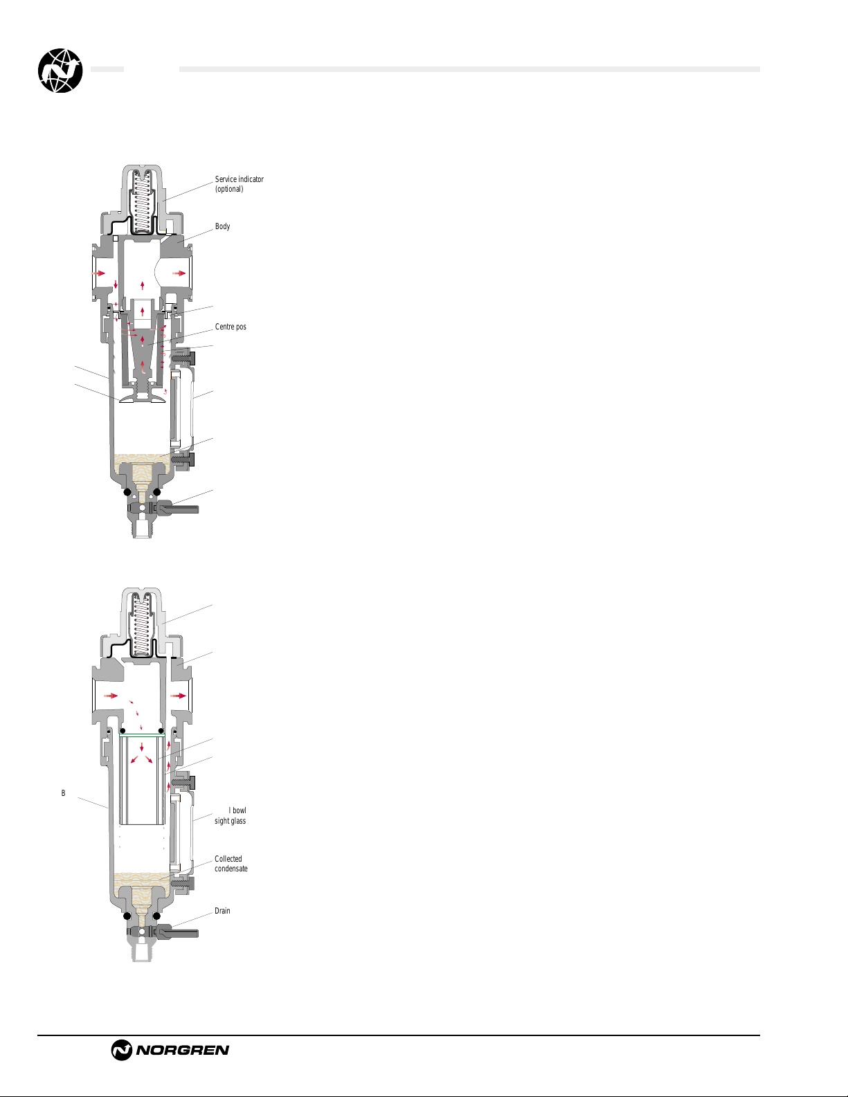
1.1.1 How Do General Purpose Filters Work?
The dirt and moisture-laden air enters the inlet port
and is directed into the louvers which centrifugally
separate the entrained liquids and dirt which fall to
the bottom of the bowl. Near the bottom of the bowl
a baffle creates a quiet zone, preventing the
turbulent air re-entraining the contaminants. The air,
now free of water droplets and large dirt particles,
passes through the filter element which removes
small dirt particles. Solid particles eventually plug
the element necessitating replacement.
1.1.2 How Do Oil Removal Filters Work?
Air enters the filter and passes through the
element from inside to outside, where oil aerosols
impinge on the borosilicate micro-fibers and are
coalesced into larger drops. The drops are carried
through the element until they reach the outer
porous sock. The outer sock, because of its cellular
construction, retains these liquids and allows them
to drain by gravity to the bottom of the bowl.
Solid partilces are retained in the element
and cause the pressure drop to slowly increase
throught the working life of the element. When the
pressure drop across the element reaches 10 psid,
the service life indicator on top of the filter will
show more red than green and the element should
be replaced.
1.1.3 How do Vapor removal Filters Work?
Carbon filters are used to remove oil vapors and
odors. The activated carbon has a porous structure
which results in a large surface area. The oil vapors
are attracted and adhere to this surface. There is
usually a small sintered medium included in an
activated carbon element to prevent the carbon
particles from migrating downstream. The carbon
filter reduces the maximum oil content of air leaving
the filter to 0.003ppm at 70°F, i.e. To ISO 8573 class
1.7.1. If protected upstream by general and oil
removal filters life is between 400 and 1000 hours.
1.1.4 Why use a Pre-Filter?
A pre-filter is simply a general purpose filter placed
upstream of a higher grade filter to remove the
majority of the water and larger particle
contaminants and thus lengthen the life of the higher
grade filter element.
A 5 micron pre-filter should always be used
ahead of an oil removal filter.
An oil removal (coalescing) filter must be
used ahead of a vapor removal adsorbing filter.
1.2 AIR QUALITY
1.2.1 What is ISO 8573?
(See ALE-1-G for specification)
This is an international standard on air quality. It
covers compressed air for general industrial use.
The air quality is specified using a 3 digit
code expressing the remaining content of a specific
contaminant after the filter (or dryer).
1.2.2 Air Classes for Norgren Filters:
Particulate filters condition compressed air to
different degrees, dependent on the micron rating of
the filter. The finer filter, 5 µm, will achieve ISO 8573
class 3.7. or class 3. Applying a 40 µm filter will
result in ISO 8573 class 5.7. or class 5 air.
Coalescing filters improve the quality of
downstream air to ISO 8573 class 1.7.2, the particle
size is reduced down to 0.01µm, with a remaining
oil content of less than 0.01ppm. Coalescing filters
cannot remove oil which is in the vapor state in the
supply air. One way to remove vapor is to reduce the
temperature of the air flow allowing the vapor to
condense, alternatively remove the vapor chemically
using an activated carbon filter.
Bowl
Baffle
Bowl
Service indicator
(optional)
Body
Louvre
Centre post
Element
Metal bowl
sight glass
Collected
condensate
Drain
Service indicator
Body
Element
Outer sock
Metal bowl
sight glass
Collected
condensate
Drain
Page 3
Filters
Littleton, CO USA Phone 303-794-2611 www.norgren.com
ALE-Filter
Figure 1. (See “Rating Filter Elements and ISO
Standard 8573-1” in this section.
RECOMMENDED FILTRATION LEVELS.
Application
Typical Quality Classes
Oil Dirt
Air agitation 1 3
Air bearings 2 2
Air gauging 2 2
Air motors 4 4
Brick and glass machines 5 4
Cleaning of machine parts 3 4
Construction 4 5
Conveying, granular products 2 4
Conveying, powder products 1 3
Fluidics, power circuits 2 5
Fluidics, sensors 2 3
Foundry machines 4 5
Food and beverages 1 1
Hand operated air tools 5 5
Machine tools 5 4
Mining 5 5
Micro-electronics manufacture 1 1
Packaging and textile machines5 3
Photographic film processing 1 2
Pneumatic cylinders 3 5
Pneumatic tools 5 4
Pneumatic tools (high speed) 4 3
Process control instruments 2 3
Paint spraying 1 1
Sand Blasting 4 5
Welding macines 5 5
General Workshop air 5 4
1.2.3 What Micron Ratings are Available?
The standard Norgren general purpose elements are
40 and 5 microns, with 40 microns being suitable
for most industrial applications. Certain industries
have 25 or 75 micron as a standard and some
product ranges have these options available.
For a given element size, the smaller the
micron rating the higher the pressure drop across
the filter. The service life between cleaning is also
less for the smaller micron filters, as small holes
plug more quickly than bigger holes.
1.2.4 How do Service Life Indicators Work?
The service life (pressure drop) indicator found on
top of coalescing or general purpose filters is green
when the filter is new. As a pressure differential
develops across the filter element with use, a spring
biased red outer sleeve is pushed up. When more
red is visible than green, then the pressure
differential across the element is in excess of 10 psi
(0.7 bar) and the element should be replaced.
1.2.5 When does the Carbon Pack Indicator Turn
Pink?
The white ring around the base of the vapor
removal carbon pack turns pink in the presence of
liquid oil. Therefore if the ring turns pink the
coalescing filter is passing liquid oil and needs
replacing. If this occurs soon after the filter has
been installed then it usually indicates a seal failure
in the coalescing filter. Remember that visual
detection is a not a substitute for scheduled
maintenance.
1.2.6 How Long does an Element Last?
This depends entirely on the quality of the inlet air.
If it is very poor the elements will need replacing
more frequently.
In general, air service equipment should
be maintained annually. Use, quality of air and
condition at examination may indicate adjustment
of the maintenance interval.
The following guidelines can be given:
General Purpose Replace/maintain annually. The
Filter: element can lose 15% efficiency
each time it is cleaned. Elements
are low cost, so it is advisable to
replace them.
Coalescing: Evaluate after 12 months of
servicing. If the pressure drop
across the element exceeds 10
psig (0.7bar) then the element
requires changing.
Activated Carbon Should be changed every 1,000
Packs: hours usage or when odor is
detected. The life depends
significantly on ambient
temperature.
1.3 PLASTIC BOWLS
Norgren transparent plastic bowls are made from
polycarbonate. Some competitors use other
materials such as Grilamid.
Both these materials are extremely resilient and have
an excellent safety record. However these
transparent plastics will degrade when subjected to
excessive heat, solvents and some chemicals, which
can lead to crazing and finally bowl failure.
Over the last few years metal bowls and
guarded plastic bowls have become increasingly
popular driven by the emergence of guidelines
recommending the use of guards.
Some organizations have their own internal
standards which call for guarded plastic or metal
bowl and the general market trend is away from
plastic bowls in the 1/2” or above port size units.
This trend is reflected in our latest Excelon 74 and
Olympian Plus product ranges. Plastic bowls remain
the most common option for 1/4” and smaller units.
Never use polycarbonate bowls at
conditions which exceed the maximum rated
pressure and temperature of 150 psig (10 bar) and
125°F (50°C).
Certain chemicals, common in some oils
and solvents, can attack polycarbonate and cause
the bowl to burst. If the compressor intake is located
in an area containing incompatible vapors, these
contaminants can be drawn into the compressor and
conveyed to the bowl in the compressed air. This
can result in bowl failure.
Synthetic compressor oils may be drawn in
from the compressor and can also result in bowl
failure.
If doubt exists as to the compatibility of
certain fluids with polycarbonate, please contact
Applications Engineering.
Metal bowls should be used where
temperatures exceed 125°F (50°C) and/or pressures
exceed 150 psig (10 bar), or when materials are
present which are incompatible with polycarbonate.
Maximum rated operating conditions for metal
bowls depend on the range; check APC-104.
Page 4

Filters
Littleton, CO USA Phone 303-794-2611 www.norgren.com
ALE-Filter
1.4 DRAINS
1.4.1 Semi Automatic:
A semi-auto drain is one which operates when the
air-line is depressurized eg at the end of a shift. It is
a normally open two-way valve which is held closed
by 7-10 psig (0.7-0.8 bar). When the filter is
pressurized, the drain may be operated manually by
pushing the tube, which protrudes outside the bowl,
upwards.
1.4.2 Automatic:
An automatic drain is a two-way valve, which will
close when the system is pressurized. The drain
opens when the float rises due to accumulated liquid
and on depressurization.
1.4.3 Where should an Automatic Drain be Used?
Automatic Drains should be used where the filter
location may make servicing difficult, where filters
may be hidden from view and consequently be
overlooked or where equipment is in continual use.
Areas where large quantities of liquid may
accumulate over a short period of time should also
be equipped with auto-drain filters. High labor costs
for draining a large number of filters manually will
generally justify the use of auto-drains.
Machines which have been shut down for a
long period of time, such as over a weekend, can
draw slugs of water during start-up which can
overload a filter unless drained immediately. (This
situation can normally be handled by a drip leg
drain, see.)
Norgren float type automatic drains are
‘normally open’ type drains. During periods when
the air line pressure is shut off, the automatic drain
will open allowing liquids to drain rather than flood
the air line piping system. When re-pressurizing the
air line, the automatic drain valve will close when
pressure reaches approximately 10 psig (0.7bar).
This results in a flow through the drain to
atmosphere of about 1.77 scfm (0.84dm3/s) until
the valve automatically closes. (See 1.4.4 below.)
1.4.4 Where should a Low Flow Automatic Drain
be used?
In systems where the compressor capacity is
insufficient to close a number of standard auto
drains a ‘low flow’ drain is available which requires
only 0.5 scfm flow before closing. An ultra low flow
auto drain is also available. ‘Low flow’ drains have
less clearance around the valve for expelling
contaminants, so should only be used where the
standard unit cannot be used. ‘Low flow’ drains can
be identified by red plastic parts.
1.4.5 07 Automatic (spitter) Drain:
When a rapid increase in flow occurs through the
filter it results in the pressure above the drain’s
diaphragm being less than that below it. This
differential pressure causes the drain to
momentarily lift and ‘spit’ out the condensate
collected underneath the drain.
1.4.6 Where should a Drip Leg Drain be Used?
The drip leg drain is a system protection device.
Most compressed air distribution systems have
varying flows and/or are shut down at the end of a
working day. As the system cools, water in the
compressed air condenses and collects in the
distribution pipe work. This water will run along the
pipe work and settle at the low point(s). On start up
of the plant this water can be pushed under
pressure into the nearest device or process and
cause malfunction or damage.
By running a vertical pipe down from
these low points water will flow into the drip leg
drain where the automatic drain will expel it.
A filter screen within the drip leg drain
prevents particles interfering with the auto-drain
operation. A ball valve should be included above
the drip leg drain to allow for maintenance when
the system is running.
1.5 PERFORMANCE
1.5.1 Performance of General Purpose Filters
Filters have their flow measured in terms of the
pressure drop across them. As the flow increases
then the pressure drop also increases. These
pressure drops are energy losses in the system.
A well designed filter not only removes
water and particles efficiently, but also has a low
pressure drop at a given flow. The flow figures
quoted in Norgren catalogues for general purpose
filters are at a pressure drop of 5 psig (0.3 bar),
from a 100 psig (7 bar) inlet pressure.
Beware! not all competitors quote their
flows under the same conditions. If a higher inlet
pressure is used or a higher pressure drop is quoted
then the apparent flow will be higher. This does not
mean it is a better unit , simply that a different point
on the curve has been selected. Often the only way
to compare units is to test them under the same
laboratory conditions.
1.5.2 Performance of Coalescing Filters:
The maximum flow of an oil removal filter is usually
determined by the oil removal efficiency under
saturated conditions. In the catalog there are
maximum flows quoted ‘to maintain stated oil
removal characteristics.’ These are the steady state
flows which should not be exceeded to guarantee
that the oil in the outlet air remains below the
0.01ppm (parts per million) quoted. Cyclic or
pulsating flows will result in oil carry over, as will
elevated temperatures.
If a higher oil carry over is acceptable (or
there is no oil in the air-line) then higher flows are
achievable, and will be determined by the
‘acceptable’ pressure drop. For a new (dry) element
a flow which gives a pressure drop of less than 5
psid (0.3 bar) is recommended.
Page 5
Filters
Littleton, CO USA Phone 303-794-2611 www.norgren.com
ALE-Filter
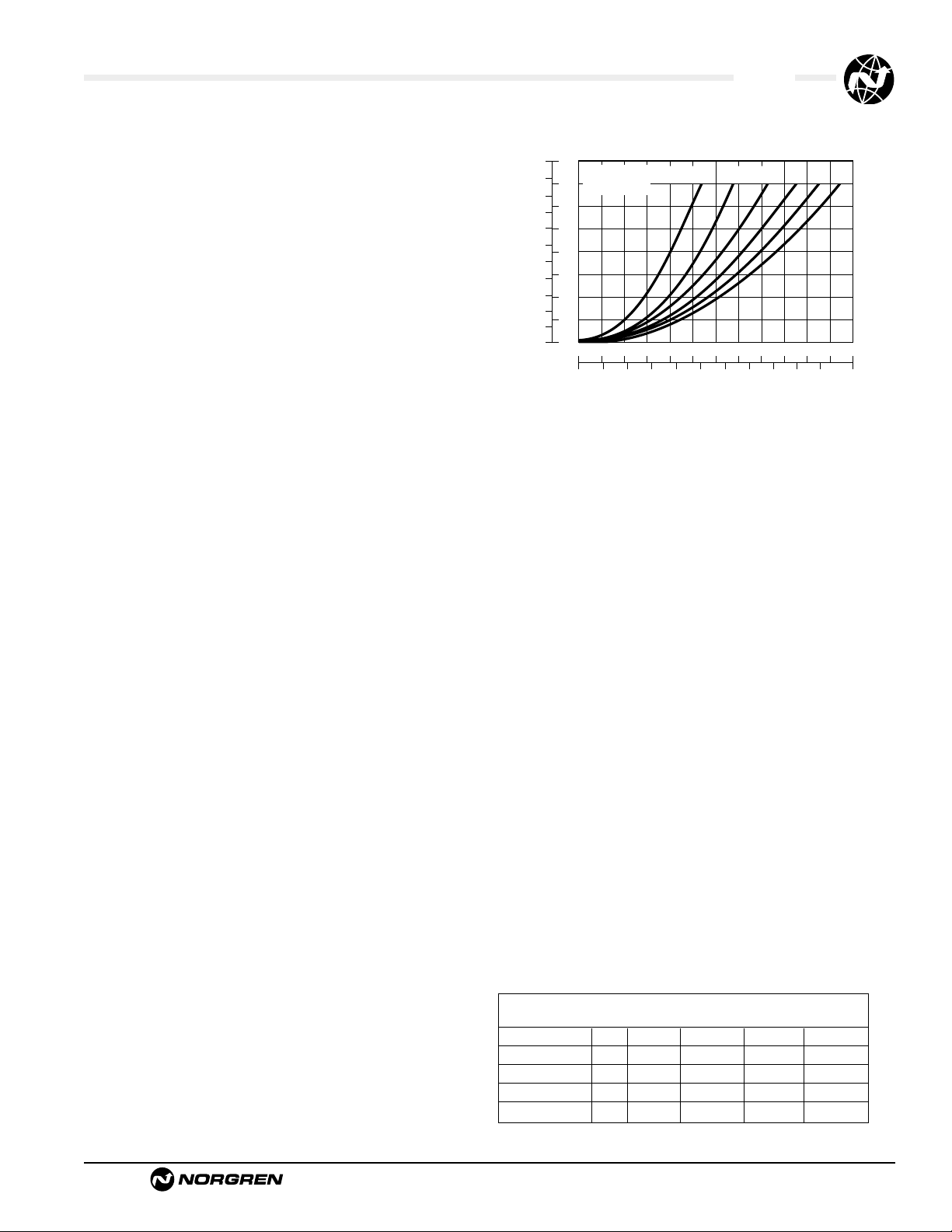
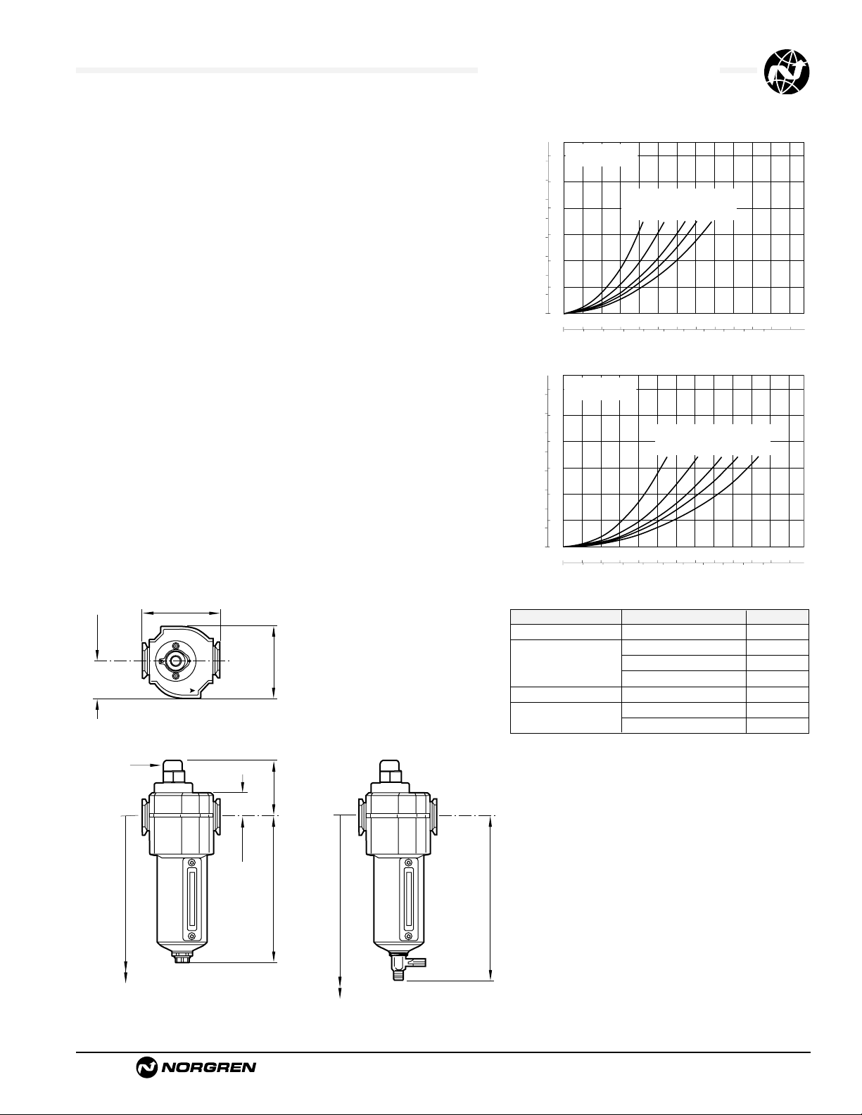
1.6 FILTER SIZING
Selecting the proper size of filter for any
application should be done by determining the
maximum allowable pressure drop which can
be caused by the filter. The pressure drop can
be determined by referring to flow curves
provided by the manufacturer.
The flow characteristic curves should relate to
the fluid used, pressure, pipe port size and
micron rating of the filter element. Often the
parameters of pressure and flow are labeled in
metric and imperial units. The vertical axis is
the pressure drop across the filter, and the
horizontal axis is the air flow through the filter.
Each curved line represents the filter flow and
pressure drop characteristics for different
operating pressures.
Example Find the pressure drop across the
filter when operating at 90 psig (6.2 bar) and
when 50 scfm (24 dm
3
/s) is flowing through
the filter.
Answer Locate 50 scfm (24 dm3/s) on the
horizontal axis. Read up to the intersecting
point on the 90 psig (6.2 bar)operating curve.
The pressure drop (or ∆ p) is approximately .6
psid (.04bar) on the vertical axis on the left of
the graph. (See graph)
1.7 MEMBRANE DRYERS
For those applications where a low-pressure
dewpoint and low installation/operational cost
are required, Norgren provides an Excelon®
Membrane Dryer. This new product can
provide dewpoint suppression up to 80°F
(26°C) below ambient temperature and is
available with nominal flows of 2, 5, 10, 20,
and 30 scfm.
The Membrane Dryer is a variable dew point
suppression device constructed of an anodized
aluminum body with end caps. Inside the
body are bundles of special hollow fibers
(membranes) which are semi-permeable.
Moisture-laden air enters the fibers and water
vapor permeates through the walls to the
outside of the fibers. Dry air exits the device
through the outlet port. A small percentage of
dry air is diverted across the outside of the
fibers to sweep away and vent water vapor to
atmosphere.
This device provides variable dew point
suppression inversely related to flow. Lower
flows through a unit will increase contact time
with the membrane fibers, resulting in greater
dew point suppression. Higher flows will
result in a decreased level of dew point
suppression. Additionally, dew point
suppression is directly related to operating
pressure. Increasing the pressure applied will
result in a greater level of dew point
suppression. Therefore, it is always
recommend placing regulators downstream of
a membrane dryer to ensure the highest
pressure possible through the membrane dryer.
Model Port Outlet Inlet Purge Press.
Flow Flow Flow Drop
W07M2ANNNA 1/4" 2 scfm 2.2 scfm 0.2 scfm 0.4 psid
W72M2ANNNB 1/4" 5 scfm 5.6 scfm 0.6 scfm 0.32 psid
W72M2ANNNC 1/4" 10 scfm 11.2 scfm 1.2 scfm 0.90 psid
W74M4ANNND 1/2" 20 scfm 22.2 scfm 2.2 scfm 0.65 psid
W74M4ANNNE 1/2" 30 scfm 33.4 scfm 3.4 scfm 1.35 psid
Typical Flows for Membrane Dryers
bar d
psid
7
45
6
40
35
5
30
4
25
3
20
Pressure Drop
15
2
10
1
05
0
0
0
0 1020304050
Flow Characteristics
180
150
120
90
60
35
INLET
PRESSURE
20 40 60 80 100 120 140 160 180 200 220 scfm
psig
(bar)
(4.1)
(2.4)
60 70 80 90 100
Air Flow
(6.2
(8.3)
(10.4)
(12.5)
dm 3/s
Page 6
Filters
Littleton, CO USA Phone 303-794-2611 www.norgren.com
ALE-Filter
Malfunction Possible cause Remedy
Excessive pressure drop. Micron rating of element to small Use larger micron element size for application.
Filter element blocked. 1. Clean element (not
coalescing element). Note: Some residual
contamination will remain.
2. Replace with new element.
Flow requirement greater than Use larger filter.
filter capacity.
Dirt passing through filter. Element seals missing or Replace seal
defective. (N.B. Seals not 2. Tighten element.
required on some units).
Damaged element. Replace element.
Water passing through filter. Water level in bowl above Drain water.
baffle.
Flow capacity of filter Maintain flow within capacity
exceeded. of filter or change to filter
capable of handling desired flows.
Crazing of Polycarbonate bowl Bowl has been cleaned with Replace bowl.
or milky appearance. incompatible fluid. (Clean only in clean warm water and soap.)
Bowl is being used in an area Replace bowl.
containing fumes or vapors Eliminate source of problem or
incompatible with polycarbonate. convert from plastic to metal bowls.
Compressor oil vapor may be Replace bowl.
causing problem. Eliminate source of problem or
convert from plastic to metal bowls.
Air intake to compressor may Replace bowl.
contain fumes or vapor Eliminate source of problem or
incompatible with polycarbonate.convert from
plastic to metal bowls.
Water beyond the filter Inlet air has a high temperature Fit dryer, pre-cool air or fit
and as it cools downstream, filter immediately prior to application.
moisture condenses to water.
1.7 SIMPLE FILTER TROUBLESHOOTING
Page 7
Rating Filter Elements and ISO Standard 8573-1
Littleton, CO USA Phone 303-794-2611 www.norgren.com
ALE-Filter
Absence of an Industrial Standard for Rating
Pneumatic Filter Elements
There is not an industry wide standard for establishing the micron
rating of pneumatic filter elements. Standards by various industry
associations, including the National Fluid Power Association
(NFPA) and Inter national Standard Organization (ISO), are in
discussion. In the absence of an industr y standard, some
manufacturers of pneumatic filters make claims concerning the
micron rating of their so called “standard” element which can not
be substantiated and are probably not valid.
Norgren’s Method of Rating and Testing
Pneumatic Filter Elements
Norgren particle removal filter elements are rated by the size of
the particle they will trap (i.e., a 40-micron element will remove
particles 40-microns and larger). Norgren tests filter elements by
using standard coarse and fine test dusts of known particle size
distribution. Coarse dust consists of 12% par ticles smaller than
5-microns; fine grain dust consists of 39% particles smaller than
5-microns.Test results show that a Norgren filter element rated at
40-microns actually removes over 98% of particles 5-microns and
larger.
How to Size a Filter Element
The downstream equipment being protected determines the
micron rating of the filter element. Industrial tools, such as air
hammers and drills, typically require only a 40-micron element.
Air operated instruments and small, high speed tools typically
require a 5-micron element. Always consult the equipment
manufacturer for filtration requirements.
Generally, the smaller the micron rating of the element,
● the higher the pressure drop across the filter,
● the shor ter the element ser vice life.
Therefore, the use of a 5-micron element where a 40-micron is
adequate penalizes the customer in increased pressure losses
and frequent down time for changing or cleaning the filter element.
ISO Standard 8573-1. Compressed Air
for General Use
Contaminant’s found in industrial compressed
air systems include solid particles, water, and
oil. ISO 8573-1:1991 provides a simple method
of classifying these contaminant’s.A quality
class required for a particular application can
be defined by listing, in order, the class
required for solids, water, and oil.
Examples:
Air of Quality Class 2.2.2 is filtered to 1µm
solid particle size, dried to -40°F (-40°C)
pressure dewpoint, and filtered to an oil
concentration of 0.1mg/m
3
.
Air of Quality Class 5.3.4 is filtered to 40µm
solid particle size, dried to -4°F (-20°C)
pressure dewpoint, and filtered to an oil
concentration of 5mg/m
3
.
When a class for a particular contaminant
solid, water, or oil is not specified, the number
designating the class is replaced with a
hyphen.
Example: Air of Quality Class 1.–.1 does not
specify the pressure dewpoint.
Table 1. Summary of ISO 8573-1:1991 Air
Quality Classes *
Solid Water Oil
Particle Maximum Maximum
Maximum Pressure Remaining
Quality Size Dewpoint Oil Content
Class µm °F (°C) mg/m
3
** (ppm)
1 0.1 -94 (-70) 0.01 (.0084)
2 1 -40 (-40) 0.1 (.084)
3 5 -4 (-20) 1 (.84)
4 15 38 (3) 5 (4.2)
5 40 45 (7) 25 (21)
6 — 50 (10) —
* See ISO standard 8573-1 for complete
information.
** At 1 bar absolute pressure.
Page 8
Littleton, CO USA Phone 303-794-2611 www.norgren.com
ALE-1-1
Section 1
F07 Miniature General Purpose Filter 1/8" and 1/4" Ports . . . . . . . . .ALE-1-2
F72G Excelon General Purpose Filter 1/4" and 3/8" Ports . . . . . . . .ALE-1-4
F73G Excelon General Purpose Filter 1/4" to 1/2" Ports . . . . . . . . . .ALE-1-6
F74G Excelon General Purpose Filter 1/4" to 3/4" Ports . . . . . . . . . .ALE-1-8
F64G Olympian Plus General Purpose Filter 1/4" to 3/4" Ports . . . .ALE-1-10
F68G Olympian Plus General Purpose Filter 3/4" to 1-1/2" Ports . .ALE-1-12
F17 General Purpose Filter 3/4" to 1-1/2" Ports . . . . . . . . . . . . . . . .ALE-1-14
F18 General Purpose Filter 1-1/2" and 2" Ports . . . . . . . . . . . . . . . .ALE-1-16
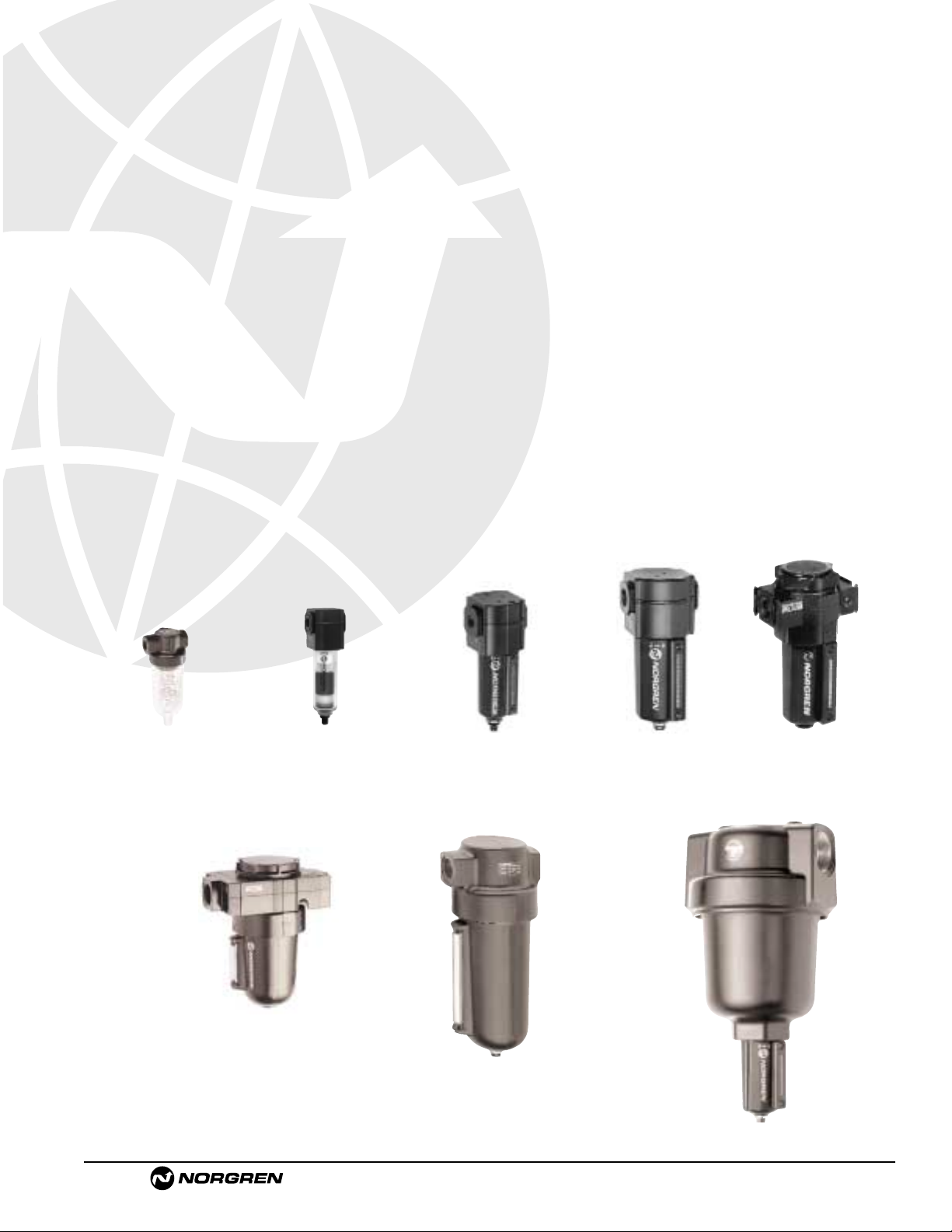
General Purpose Filters
Compressed air, general
purpose filters are available in
modular or inline models, in port
sizes from 1/8" to 2".
F07
F72G
F73G F74G F64G
F17
F68
F
18
Page 9
See Section ALE-24 for Accessories
Littleton, CO USA Phone 303-794-2611 www.norgren.com
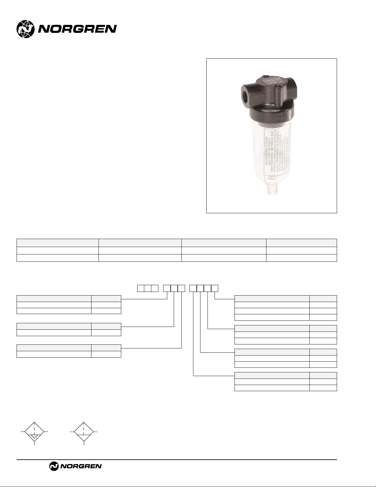
F07
● Compact design
● Protects air operated devices by removing liquid and
solid contaminants
● Screw-on bowl reduces maintenance time
● Can be disassembled without the use of tools or
removal from the air line
Miniature Series 07 General Purpose Filter
1/8" and 1/4" Port Sizes
ALE-1-2
Port Size Model Numbers Flow scfm (dm3/s) * Weight lbs (kg)
1/8" F07-100-A1TA 19 (9) 0.28 (0.13)
1/4" F07-200-A1TA 24 (11.5) 0.28 (0.13)
Ordering Information. Models listed include PTF threads, automatic drain, transparent bowl and 5 µm element.
* Approximate flow at 90 psig (6.3 bar) inlet pressure and 5 psig (0.35 bar) pressure drop.
Alternative Models
Port Size Substitute
1/8" 1
1/4" 2
Threads Substitute
PTF A
ISO Rc taper B
ISO G parallel G
Option Substitute
Not applicable 0
Bowl Substitute
Transparent T
Metal M
Option Substitute
Not applicable 0
Element Substitute
5 µm 1
40 µm 3
Drain Substitute
Automatic A
Manual M
-
★★★★★
★
-
0★F 7
ISO Symbols
Auto Drain
Manual Drain
Page 10
F07 General Purpose Filters
Littleton, CO USA Phone 303-794-2611 www.norgren.com
ALE-1-3
Technical Data
Fluid: Compressed air
Maximum pressure:
Transparent bowl: 150 psig (10 bar)
Metal bowl: 250 psig (17 bar)
Operating temperature:*
Transparent bowl: -30° to 125°F (-34° to 50°C)
Metal bowl: -30° to 175°F (-34° to 80°C)
* Air supply must be dry enough to avoid ice formation at temperatures below
35°F (2°C)
Particle removal: 5 µm or 40 µm filter element
Air quality: Within ISO 8573-1, Class 3 and Class 5 (particulates)
Typical flow at 90 psig (6.3 bar) inlet pressure at 5 psig (0.35 bar) pressure drop:
1/8" Ports, 5 µm element: 19 scfm (9 dm3/s)
1/4" Ports, 5 µm element: 24 scfm (11.5 dm
3
/s)
Nominal bowl size: 1 fluid ounce (31 ml)
Drain connection: 1/8" pipe thread
Automatic drain operation:Spitter type drain operates momentarily when a rapid
change in air flow occurs or when the supply pressure is reduced.
Materials
Body: Zinc
Bowl
Transparent: Polycarbonate
Metal: Zinc (without sight glass)
Element: Sintered polypropylene
Elastomers: Neoprene & nitrile
For water extraction information please contact Applications Engineering.
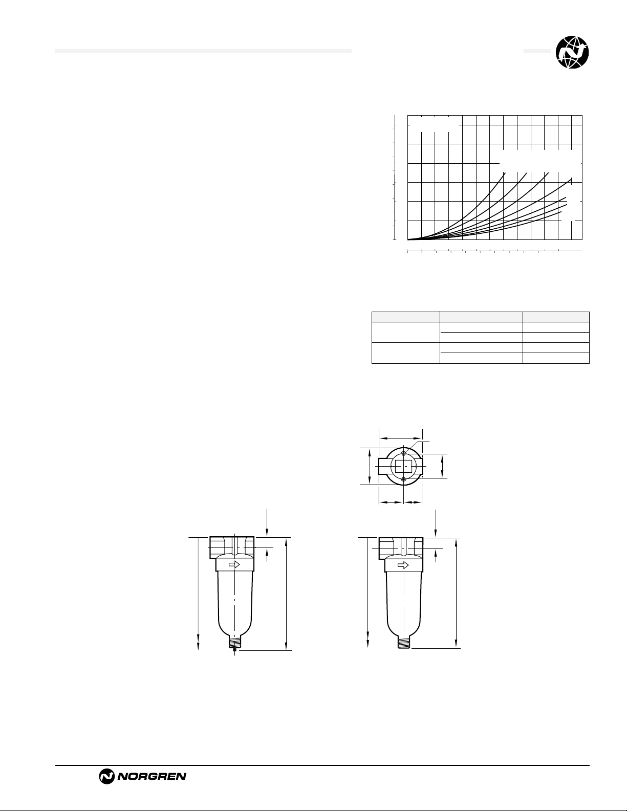
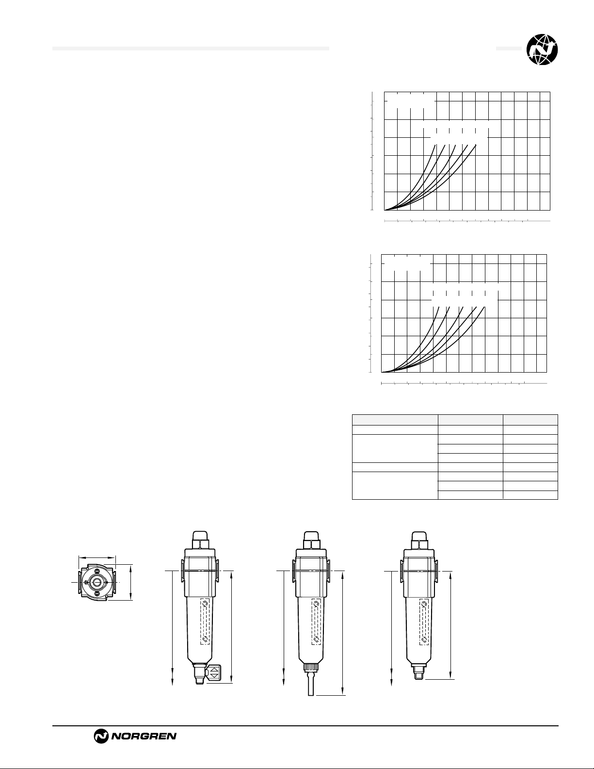
Typical Performance Characteristics
FLOW CHARACTERISTICS
0 2 4 6 8 10 dm3/s
AIR FLOW
0 4 8 12 16 20 scfm
0.8
0.6
0.4
0.2
0
PRESSURE DROP
bar d
10
8
6
4
2
0
psid
PORT SIZE: 1/4"
5 µm ELEMENT
INLET PRESSURE: psig (bar)
25
(1.8)
60
(4.0)
40
(2.8)
90
(6.3)
120
(8)
180
(12)
150
(10)
0.157 (4) Dia †
0.5 (13) Deep †
n
n
1.45 (37)
0.91
(23)
0.73
(19)
0.91
(23)
1.63 (42)
6.07 (154) *
0.38 (10)
4.10 (104)
6.22 (158) **
4.25 (108)
0.38 (10)
** Minimum clearance to remove bowl.
† Mounting holes.
Service Kits
Item Type Part number
Service kit
5 µm element 3652-17
40 µm element 3652-18
Replacement drains
Manual 773-03
Automatic 3654-02
Service kit includes element, element gasket, and bowl o-ring.
All Dimensions in Inches (mm)
Manual Drai
Automatic Drai
Page 11
See Section ALE-24 for Accessories
Littleton, CO USA Phone 303-794-2611 www.norgren.com
F72G
● Excelon design allows in-line or modular installation
● High efficiency water and particle removal
● Quick release bayonet bowl
● Highly visible, prismatic liquid level indicator lens on
metal bowls
● Optional service indicator turns from green to red
when the filter element needs to be replaced
● Optional electrical service indicator also available
● Modular installations with Excelon 72, 73, and 74
series can be made to suit particular applications
Excelon 72 General Purpose Filter
1/4" and 3/8" Port Sizes
ALE-1-4
Ordering Information. Models listed include PTF threads, automatic drain, long transparent bowl without guard, 40 µm element.Models do not
include the service life indicator.
† Typical flow with a 40µm element at 90 psig (6.3 bar) inlet pressure and 5 psig (0.35 bar) pressure drop.
Port Size Model Flow†scfm (dm3/s) Weight lb (kg)
1/4" F72G-2AN-AL3 55 (26) 1.15 (0.52)
3/8" F72G-3AN-AL3 55 (26) 1.15 (0.52)
F 7 2-G
★ ★
-
★★ ★ ★
Port Size Substitute
1/4" 2
3/8" 3
Threads Substitute
PTF A
ISO Rc taper B
ISO G parallel G
Drain Substitute
1/4 turn manual Q
Semi automatic S
Auto drain* A
Element Substitute
5 µm 1
25 µm 2
40 µm 3
Service Life Indicator Substitute
With (visual) D
With (electrical) E
Without N
Alternative Models
Bowl Substitute
Metal with liquid level indicator E
Transparent without guard L
Transparent with guard W
ISO Symbols
Auto Drain
Manual Drain
Page 12
F72G General Purpose Filters
Littleton, CO USA Phone 303-794-2611 www.norgren.com
ALE-1-5
Technical Data
Fluid: Compressed air
Maximum pressure:
Transparent bowl: 150 psig (10 bar)
Metal bowl:
Manual or semi automatic drain: 250 psig (17 bar)
Automatic drain: 150 psig (10 bar)
Operating temperature*:
Transparent bowl: -30° to 125°F (-34° to 50°C)
Metal bowl: -30° to 150°F (-34° to 65°C)
*
Air supply must be dry enough to avoid ice formation at temperatures below 35°F (2°C).
Particle removal: 5 µm, 25 µm or 40 µm.Within ISO 8573-1, Class 3 and Class 5
Typical flow at 90 psig (6.3 bar) inlet pressure and 5 psig (0.35 bar) pressure drop:
5 µm element: 47 scfm (22 dm
3
/s)
40 µm element: 55 scfm (26 dm3/s)
Manual drain connection:Will fit 1/8-27 and 1/8-28 pipe thread.
Semi automatic drain connection: Push on 5/16" (8 mm) ID tube
Semi automatic drain operating conditions (pressure operated):
Bowl pressure required to close drain: Greater than 1.5 psig (0.1 bar)
Bowl pressure required to open drain: Less than 1.5 psig (0.1 bar)
Minimum air flow required to close drain: 1 scfm (0.5 dm
3
/s)
Manual operation: Lift stem to drain bowl
Automatic drain connection:Will fit 1/8-27 and 1/8-28 pipe thread. - Flexible tube
with 3/16" (5mm) minimum I.D.can be connected to the automatic drain. Drain
may fail to operate if the tube I.D. is less than 3/16" (5mm). Avoid restrictions in
the tube.
Automatic drain operating conditions (float operated):
Bowl pressure required to close drain: Greater than 5 psig (0.35 bar)
Bowl pressure required to open drain: Less than 3 psig (0.2 bar)
Minimum air flow required to close drain: 0.2 scfm (0.1 dm
3
/s)
Manual operation: Depress pin inside drain outlet to drain bowl
Nominal bowl size:
Long bowl: 2.2 fluid ounce (65 ml)
Materials
Body: Zinc
Bowl
Transparent: Polycarbonate
Guard for transparent bowl:Zinc
Metal: Zinc
Metal bowl liquid level indicator lens:
Transparent nylon
Element: Sintered polypropylene
Elastomers: Neoprene and nitrile
An automatic drain is a two-way valve, which will close when the system is
pressurized.The drain opens when the float rises due to accumulated liquid
and on depressurization.
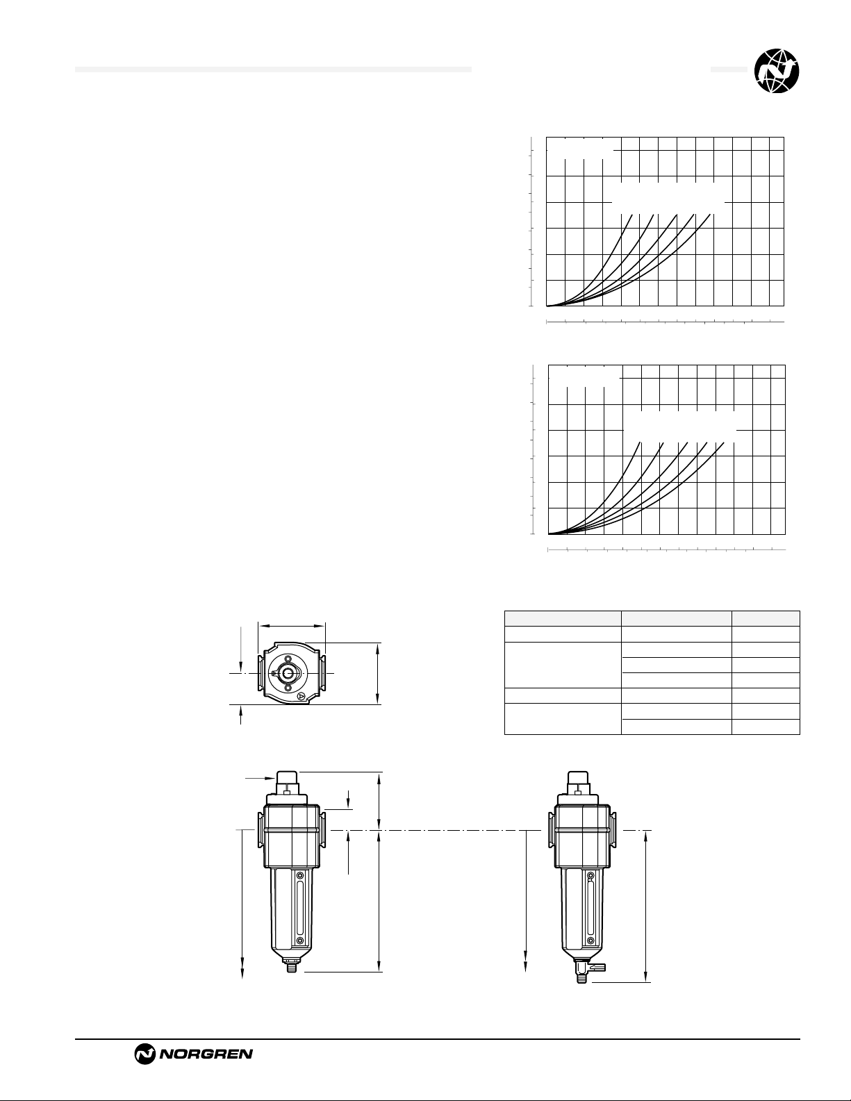
Typical Performance Characteristics
Service Kits
Item Type Part Number
Service kit Seal and gasket 4380-500
5 µm 5925-03
Elements 25 µm 5925-01
40 µm 5925-02
Liquid level lens kit Prismatic 4380-030
1/4 turn manual 619-50
Replacement drains Semi automatic 5379-RK
Automatic 4000-50R
Service kit includes drain and bowl o-rings.
† Minimum clearance required to remove bowl.
All Dimensions in Inches (mm)
PORT SIZE: 1/4"
psid
bar d
5 µm ELEMENT
0.8
10
0.6
8
6
0.4
PRESSURE DROP
4
0.2
2
0
0
0 20 40 60 80 100 120 scfm
0 10 20 30 40 50 dm3/s
PORT SIZE: 1/4"
psid
bar d
40 µm ELEMENT
0.8
10
0.6
8
6
0.4
PRESSURE DROP
4
0.2
2
0
0
0 20 40 60 80 100 120 scfm
0 10 20 30 40 50 dm3/s
FLOW CHARACTERISTICS
INLET PRESSURE - psig (bar g)
36
(2.5)58(4.0)91(6.3)
FLOW CHARACTERISTICS
INLET PRESSURE - psig (bar g)
36
(2.5)58(4.0)91(6.3)
116
(8.0)
AIR FLOW
AIR FLOW
116
(8.0)
150
(10.0)
150
(10.0)
1.97 (50)
1.89 (48)
(Top)
7.83 (199) †
Bowl with
1/4 Turn Manual Drain
5.83 (148)
9.84 (250) †
Bowl with
Semi auto Drain
7.48 (190)
7.52 (191) †
Bowl with
Automatic Drain
5.51 (140)
Page 13

See Section ALE-24 for Accessories
Littleton, CO USA Phone 303-794-2611 www.norgren.com
F73G
● Excelon design allows in-line or modular installation
● Quick release bayonet bowl
● Highly visible, prismatic liquid level indicator lens
● Optional mechanical service indicator turns from
green to red when the filter element needs to be
replaced
● Optional electrical service indicator provides
electrical output when the filter element needs to be
replaced
● Modular installations with Excelon 72, 73, and 74
series can be made to suit particular applications
Excelon 73 General Purpose Filter
1/4", 3/8", 1/2" Port Sizes
ALE-1-6
Ordering information.
Models listed include PTF threads, automatic drain, metal bowl with liquid level indicator, and a 40 µm element.
* Typical flow with a 40 µm element at 90 psig (6.3 bar) inlet pressure and 5 psig (0.35 bar) pressure drop.
Alternative Models
F 7 3-G
★ ★
-
★★ ★ ★
Threads Substitute
PTF A
ISO Rc taper B
ISO G parallel G
Service Indicator Substitute
With electrical service indicator * E
With mechanical service indicator D
Without N
Drain Substitute
Automatic A
Manual, 1⁄4 turn Q
Element Substitute
5 µm 1
25 µm 2
40 µm 3
Bowl Substitute
Metal with liquid level indicator D
Transparent with guard P
Transparent T
Port Size Substitute
1/4" 2
3/8" 3
1/2" 4
Port Size Model Flow* scfm (dm3/s) Weight lb (kg)
1/4" F73G-2AN-AD3 53 (25) 1.1 (0.50)
3/8" F73G-3AN-AD3 65 (31) 1.1 (0.50)
1/2" F73G-4AN-AD3 69 (33) 1.1 (0.50)
ISO Symbols
Auto Drain
Manual Drain
Page 14
F73G General Purpose Filters
Littleton, CO USA Phone 303-794-2611 www.norgren.com
ALE-1-7
All Dimensions in Inches (mm)
Technical Data
Fluid: Compressed air
Maximum pressure:
Transparent bowl: 150 psig (10 bar)
Metal bowl: 250 psig (17 bar)
Operating temperature*:
Transparent bowl: -30° to 125°F (-34° to 50°C)
Metal bowl: -30° to 175°F (-34° to 80°C)
* Air supply must be dry enough to avoid ice formation at temperatures below 35°F (2°C).
Particle removal: 5 µm, 25 µm, or 40 µm filter element
Air quality: Within ISO 8573-1, Class 3 and Class 5 (particulates)
Typical flow with a 40 µm element at 90 psig (6.3 bar) inlet pressure and 5 psig
(0.35 bar) pressure drop: 65 scfm (31 dm
3
/s)
Manual drain connection:Will fit 1/8-27 and 1/8-28 pipe thread.
Automatic drain connection:Will fit 1/8-27 and 1/8-28 pipe thread. - Flexible tube
with 3/16" (5mm) minimum I.D.can be connected to the automatic drain. Drain
may fail to operate if the tube I.D. is less than 3/16" (5mm). Avoid restrictions in
the tube.
Automatic drain operating conditions (float operated):
Bowl pressure required to close drain: Greater than 5 psig (0.3 bar)
Bowl pressure required to open drain: Less than 3 psig (0.2 bar)
Minimum air flow required to close drain: 0.2 scfm (0.1 dm
3
/s)
Manual operation: Depress pin inside drain outlet to drain bowl
Nominal bowl size: 3.5 fluid ounce (0.1 liter)
Materials
Body: Aluminum
Bowl
Transparent: Polycarbonate
Transparent with guard: Polycarbonate, steel guard
Metal: Aluminum
Metal bowl liquid level indicator lens:Transparent nylon
Element: Sintered polypropylene
Elastomers: Neoprene and nitrile
An automatic drain is a two-way valve, which will close when the system is
pressurized.The drain opens when the float rises due to accumulated liquid
and on depressurization.
PRESSURE DROP
0.6
0.4
0.2
0
bar d
10
8
6
4
2
0
psid
PORT SIZE: 3/8"
ELEMENT: 5 µm
36
(2.5)
58
(4.0)
150
(10.0)
90
(6.3)
116
(8.0)
INLET PRESSURE: psig (bar)
01020304050dm
3
/s
AIR FLOW
0 20 40 60 80 100 scfm
FLOW CHARACTERISTICS
Typical Performance Characteristics
** Minimum clearance required to remove bowl.
6.15 (156)
1/4 Turn Manual Drain
8.50 (216) **
1.00 (25)
2.36 (60)
Automatic Drain
Optional
Mechanical
Service
Indicator
5.80 (147)
8.15 (207) **
2.68 (68)
2.45 (62)
1.22 (31)
Service kit includes automatic drain seal and bowl seal.
Service Kits
Item Type Part Number
Service kit Seal & Gasket 4380-600
Replacement elements
5 µm 4438-01
25 µm 4438-02
40 µm 4438-03
Liquid level lens kit Prismatic 4380-020
Replacement drains
Automatic 4000-51R
Manual quarter turn 619-50
PORT SIZE: 3/8"
psid
bar d
ELEMENT: 40 µm
10
0.6
8
6
0.4
PRESSURE DROP
4
0.2
2
0
0
0 20 40 60 80 100 scfm
01020304050dm
FLOW CHARACTERISTICS
INLET PRESSURE: psig (bar)
58
36
(2.5)
(4.0)
AIR FLOW
(6.3)
90
(8.0)
116
150
(10.0)
3
/s
Page 15
See Section ALE-24 for Accessories
Littleton, CO USA Phone 303-794-2611 www.norgren.com
F74G
● Excelon design allows in-line or modular installation
● Quick release bayonet bowl
● Highly visible, prismatic liquid level indicator lens
● Optional mechanical service indicator turns from
green to red when the filter element needs to be
replaced
● Optional electrical service indicator provides
electrical output when the filter element needs to be
replaced
● Modular installations with Excelon 72, 73, and 74
series can be made to suit particular applications
Excelon 74 General Purpose Filter
3/8",1/2",3/4" Po rt S ize s
ALE-1-8
Ordering information.
Models listed include PTF threads, automatic drain, metal bowl with liquid level indicator, and a 40 µm element.
* Typical flow with a 40 µm element at 90 psig (6.3 bar) inlet pressure and 5 psig (0.35 bar) pressure drop.
Alternative Models
F 7 4-G
★ ★
-
★★ ★ ★
Threads Substitute
PTF A
ISO Rc taper B
ISO G parallel G
Service Life Indicator Substitute
With (visual) D
With (electrical) E
Without N
Drain Substitute
Automatic A
Manual, 1⁄4 turn Q
Element Substitute
5 µm 1
25 µm 2
40 µm 3
Bowl Substitute
Metal with liquid level indicator D
Transparent with guard P
Port Size Substitute
3/8" 3
1/2" 4
3/4" 6
Port Size Model Flow* scfm (dm3/s) Weight lb (kg)
3/8" F74G-3AN-AD3 112 (53) 1.82 (0.83)
1/2" F74G-4AN-AD3 140 (66) 1.79 (0.81)
3/4" F74G-6AN-AD3 140 (66) 1.75 (0.79)
ISO Symbols
Auto Drain
Manual Drain
Page 16
F74G General Purpose Filters
Littleton, CO USA Phone 303-794-2611 www.norgren.com
ALE-1-9
Technical Data
Fluid: Compressed air
Maximum pressure
Transparent bowl: 150 psig (10 bar)
Metal bowl: 250 psig (17 bar)
Operating temperature*:
Transparent bowl: -34° to 125°F (-30° to 50°C)
Metal bowl: -34° to 175°F (-30° to 80°C)
* Air supply must be dry enough to avoid ice formation at temperatures below 35°F (2°C).
Particle removal: 5, 25, or 40 µm filter element
Air quality: Within ISO 8573-1, Class 3 and Class 5 (particulates)
Typical flow with a 40 µm element at 90 psig (6.3 bar) inlet pressure and 5 psig
(0.35 bar) pressure drop: 140 scfm (66 dm3/s)
Manual drain connection:Will fit 1/8-27 and 1/8-28 pipe thread
Automatic drain connection:Will fit 1/8-27 and 1/8-28 pipe thread. - Flexible tube
with 3/16" (5mm) minimum I.D.can be connected to the automatic drain. Drain
may fail to operate if the tube I.D. is less than 3/16" (5mm). Avoid restrictions in
the tube.
Automatic drain operating conditions (float operated):
Bowl pressure required to close drain: Greater than 5 psig (0.3 bar)
Bowl pressure required to open drain: Less than 3 psig (0.2 bar)
Minimum air flow required to close drain: 2 scfm (1 dm
3
/s)
Manual operation: Depress pin inside drain outlet to drain bowl
Nominal bowl size: 7 fluid ounce (0.2 liter)
Materials
Body: Aluminum
Bowl
Transparent: Polycarbonate with steel bowl guard
Metal: Aluminum
Metal bowl liquid level indicator lens:Transparent nylon
Element: Sintered polypropylene
Elastomers: Neoprene and Nitrile
An automatic drain is a two-way valve, which will close when the system is
pressurized.The drain opens when the float rises due to accumulated liquid
and on depressurization.
Typical Performance Characteristics
PRESSURE DROP
0.6
0.4
0.2
0
bar d
10
8
6
4
2
0
psid
36
(2.5)
58
(4.0)
150
(10.0)
90
(6.3)
116
(8.0)
INLET PRESSURE: psig (bar g)
0 20 40 60 80 100 dm3/s
AIR FLOW
0 40 80 120 160 200 scfm
PORT SIZE: 1/2"
ELEMENT: 5 µm
FLOW CHARACTERISTICS
PRESSURE DROP
0.6
0.4
0.2
0
bar d
10
8
6
4
2
0
psid
PORT SIZE: 1/2"
ELEMENT: 40 µm
36
(2.5)
58
(4.0)
150
(10.0)
90
(6.3)
116
(8.0)
INLET PRESSURE: psig (bar g)
0 20 40 60 80 100 dm3/s
AIR FLOW
0 40 80 120 160 200 scfm
FLOW CHARACTERISTICS
6.95 (177)
1/4 Turn Manual Drain
9.69 (246) **
3.15 (80)
2.36 (60)
†
1.00 (25)
2.89 (74)
1.45 (37)
Automatic Drain
Optional
Service
Indicator
6.35 (161)
9.06 (230) **
* Minimum clearance required to remove bowl.
† Dimension for alternative electrical service indicator is 1.98" (50.4 mm)
Item
Type Part Number
Service kit Seal & gasket 4380-700
Replacement elements
5 µm 4338-04
25 µm 4338-07
40 µm 4338-05
Liquid level lens kit Prismatic 4380-050
Replacement drains
Automatic (1/8 NPT outlet) 3000-10
Manual quarter turn 619-50
Service kit includes louvre/element seal, drain seal, bowl seal.
Service Kits
All Dimensions in Inches (mm)
Page 17

See Section ALE-24 for Accessories
Littleton, CO USA Phone 303-794-2611 www.norgren.com
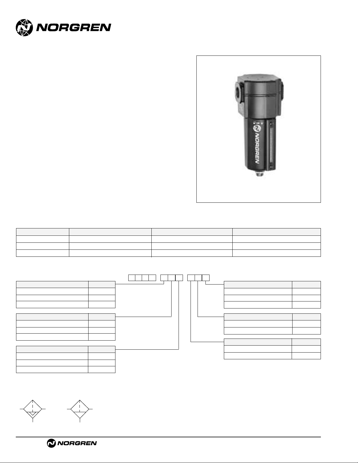
F64G
● Olympian Plus plug in design
● High efficiency water and particle removal
● Quick release bayonet bowl
● High visibility prismatic sight glass
● Optional service indicator
Olympian Plus General Purpose Filter
1/4", 3/8", 1/2", 3/4" Port Sizes
ALE-1-10
Ordering Information. Models listed include PTF threads, yoke, automatic drain, metal bo wl, 40 µm element.Models do not include the service life indicator.
† Typical flow with a 40 µm element at 90 psig (6.3 bar) inlet pressure and a 5 psig (0.35 bar) pressure drop.
Port Size Model Flow†scfm (dm3/s) Weight lb (kg)
1/4" F64G-2AN-AD3 59 (28) 3.13 (1.42)
3/8" F64G-3AN-AD3 118 (56) 3.13 (1.42)
1/2" F64G-4AN-AD3 125 (59) 2.91 (1.32)
3/4" F64G-6AN-AD3 125 (59) 3.79 (1.72)
F 6 4-G
★ ★
-
★★ ★ ★
Port Size Substitute
1/4" 2
3/8" 3
1/2" 4
3/4" 6
No yoke N
Threads Substitute
PTF A
ISO Rc taper B
ISO G parallel G
No yoke N
Drain Substitute
Auto drain A
Manual, 1/4 turn Q
Element Substitute
5 µm 1
25 µm 2
40 µm 3
Service Life Indicator Substitute
With (visual) D
With (electrical) E
Without N
Alternative Models
Bowl Substitute
Metal with liquid level indicator D
Transparent with guard P
ISO Symbols
Auto Drain
Manual Drain
Page 18

F64G General Purpose Filters
Littleton, CO USA Phone 303-794-2611 www.norgren.com
ALE-1-11
Technical Data
Fluid: Compressed air
Maximum pressure
Guarded transparent bowl: 150 psig (10 bar)
Metal bowl: 250 psig (17 bar)
Operating temperature*:
Guarded transparent bowl: -30° to 125°F (-34° to 50°C)
Metal bowl: -30° to 175°F (-34° to 80°C)
* Air supply must be dry enough to avoid ice formation at temperatures below 35°F (2°C).
Partical removal: 5 µm, 25 µm or 40 µm.Within ISO 8573-1, Class 3 and Class 5
Typical flow with 40 µm element at 90 psig (6.3 bar) inlet pressure and 5 psig
(0.35 bar) pressure drop: 125 scfm (59 dm
3
/s)
Manual drain connection:Will fit 1/8-27 and 1/8-28 pipe thread.
Automatic drain connection:Will fit 1/8-27 and 1/8-28 pipe thread. - Flexible tube
with 3/16" (5mm) minimum I.D.can be connected to the automatic drain. Drain
may fail to operate if the tube I.D. is less than 3/16" (5mm). Avoid restrictions in
the tube.
Automatic drain operating conditions (float operated):
Bowl pressure required to close drain: Greater than 5 psig (0.3 bar)
Bowl pressure required to open drain: Less than 3 psig (0.2 bar)
Minimum air flow required to close drain: 2 scfm (1 dm
3
/s)
Manual operation: Depress pin inside drain outlet to drain bowl
Nominal bowl size: 7 fluid ounce (0.2 liter)
Materials
Body: Zinc
Yoke: Zinc
Metal bowl: Aluminum
Standard metal bowl prismatic liquid level indicator lens:Gr ilamid
Optional metal bowl sight glass: Pyrex
Optional transparent bowl: Polycarbonate
Element: Polypropylene
Elastomers: Nitrile
An automatic drain is a two-way valve, which will close when the system is
pressurized.The drain opens when the float rises due to accumulated liquid
and on depressurization.
Typical Performance Characteristics
* 6.18" (157 mm) for 3/4" models
† Minimum clearance required to remove bowl.
Automatic Drain
8.54 (217)†
4.13 (105)*
1.46
(37)
2.91
(74)
Optional
Service
Indicator
1.46
(37)
6.45 (164)
2.32 (59)
7.05 (179)
1/4 Turn Manual Drain
9.14 (232)†
Service Kits
Item Type Part Number
Service kit Seal and gasket 4380-200
5 µm 4338-01
Elements 25 µm 4338-99
40 µm 4338-02
Liquid level lens kit
Prismatic 4380-040
Pyrex 4380-041
Replacement drains
Automatic 3000-10
Manual 684-84
Service kit includes port seals, louver o-ring, bowl o-ring and
drain gasket.
All Dimensions in Inches (mm)
PORT SIZE: 1/2"
psid
bar d
40 µm ELEMENT
0.8
10
0.6
8
6
0.4
PRESSURE DROP
4
0.2
2
0
0
0 40 80 120 160 200 240 scfm
0 20 40 60 80 100 dm3/s
FLOW CHARACTERISTICS
INLET PRESSURE - psig (bar g)
36
(2.5)58(4.0)91(6.3)
AIR FLOW
116
(8.0)
150
(10.0)
Page 19

Littleton, CO USA Phone 303-794-2611 www.norgren.com
F68E/G
● Olympian Plus plug in system
● Effective liquid removal and positive solid particle
filtration
● Large filter element area provides minimum pressure
drop
● Optional visual service indicator turns from green to
red when the filter element needs to be replaced
● Factory option electrical service life indicator
provides electrical output when the filter element
needs to be replaced - see page ALE-25-23.
Olympian Plus General Purpose Filter
3/4",1", 1-1/4", 1-1/2" Port Sizes
ALE-1-12
Ordering Information.
Models listed include a 1 quart bowl with 40 µm long element, automatic drain, and yoke with PTF threads.
ISO Symbols
Auto Drain
Manual Drain
Port Size Model Flow†scfm (dm3/s) Weight lb (kg)
3/4 F68E-6AN-AU3 339 (160) 2.45 (5.3)
1 F68E-8AN-AU3 403 (190) 2.33 (5.1)
1-1/4 F68E-AAN-AU3 424 (200) 2.43 (5.3)
1-1/2 F68E-BAN-AU3 424 (200) 2.30 (5.0)
F 6 8-E
★ ★
-
★★ ★ ★
Drain Substitute
Automatic A
No drain (Closed bowl) E
Manual M
Manual, 1/4 turn Q
Element Substitute
5 µm 1
25 µm 2
40 µm 3
Service Life Indicator Substitute
Visual D
Electrical E
Without N
Alternative Models
Bowl Substitute
1 quart (1 liter) without liquid level
indicator C**
1 pint (0.5 liter) without liquid level
indicator M*
1 pint (0.5 liter) with liquid level
indicator R*
1 quart (1 liter) with liquid level
indicator U**
Threads Substitute
PTF A
ISO Rc taper B
ISO G parallel G
None N
Port Size Substitute
3/4" 6
1" 8
1-1/4" A
1-1/2" B
None N
Bowl/Element Type Substitute
1 pint (0.5 liter) bowl w/short element G
1 quart (1 liter) bowl w/long element E
† Typical flow with a 40µm element at 90 psig (6.3 bar) inlet pressure and 7 psig (0.5 bar) pressure drop.
* Only available with F68G
** Only available with F68E
Page 20

13.5 (343) ¶ *
7.5 (190)*
3.11 (79) †
1.73 (44)
Optional Visual
Service Indicator
2.40
(61)
14.2 (361) ¶
8.2 (208)
13.8 (350) ¶
7.8 (197)
Manual Drain
1 Pint US
(0.5 Liter) Bowl
† For optional electrical service life indicator add 0.20" (5 mm) . *Dimension also applies to closed bottom bowl.
** For 1-1/4" and 1-1/2" ported yokes, add 0.39" (10 mm). ¶ Minimum clearance required to remove bowl.
18.2 (463) ¶
10.6 (269)
Manual Drain
17.8 (452) ¶
10.2 (258)
1/4 Turn Manual Drain
1 Quart US (1 Liter) Bowl
17.5 (445) ¶ *
Automatic Drain
.
2.40
(61)
9.9 (251)*
3.11 (79) †
1.73 (44)
Optional Visual
Service Indicator
.
1/4 Turn Manual Drain
Automatic Drain
7.48 (190)**
2.13
(54)
F68E/G General Purpose Filters
Littleton, CO USA Phone 303-794-2611 www.norgren.com
ALE-1-13
All Dimensions in Inches (mm)
Technical Data
Fluid: Compressed air
Maximum pressure: 250 psig (17 bar)
Operating temperature*: 0° to +175°F (-20° to +80°C)
* Air supply must be dry enough to avoid ice formation at temperatures below +35°F (+2°C).
Particle removal: 5, 25 or 40 µm
Air quality: Within ISO 8573-1, Class 3 and Class 5 (particulates)
Typical flow with a 40 µm element at 90 psig (6.3 bar) inlet pressure and a 7 psig
(0.5 bar) pressure drop:
403 scfm (190 dm3/s)
1/4 turn manual drain connection: 1/8" pipe thread
Automatic drain connection: 1/8" pipe thread
Automatic drain operating conditions (float operated):
Bowl pressure required to close drain: Greater than 5 psig
(0.3 bar)
Bowl pressure required to open drain: Less than 3 psig (0.2 bar)
Minimum air flow required to close drain: 2 scfm (1 dm3/s)
Manual operation: Depress pin inside drain outlet to drain bowl
Nominal bowl size:
1 pint U.S.(0.5 liter)
1 quart U.S. (1 liter)
Materials:
Body: Aluminum
Yoke: Aluminum
Bowl: Aluminum
Liquid level indicator: Pyrex
Element: Sintered bronze or polypropylene
Elastomers: Synthetic rubber
An automatic drain is a two-way valve, which will close when the system is
pressurized.The drain opens when the float rises due to accumulated liquid
and on depressurization.
s
Service Kits
Item Type Part Number
Service Kit Seal and gasket 4380-300
5 µm (1 pint bowl) 5576-97
25 µm (1pint bowl) 5576-98
Replacement 40 µm (1 pint bowl) 5576-99
Elements 5 µm (1 quart bowl) 5311-01
25 µm (1 quart bowl) 5311-02
40 µm (1 quart bowl) 5311-03
Replacement 1 pint bowl 4380-060
Sight Glass 1 quart bowl 4380-061
Automatic (G 1/8 outlet) 3000-97
Replacement Automatic (1/8 NPT outlet) 3000-10
Drains Manual 684-84
Manual, 1/4 turn 619-50
Service kit includes: Louver/element seals, drain seal, bowl seal.
Typical Performance Characteristics
PORT SIZE: 1"
psid
bar d
40 µm ELEMENT
0.8
10
0.6
8
6
0.4
PRESSURE DROP
4
0.2
2
0
0
0 80 160 240 320 400 480 scfm
0 40 80 120 160 200 dm3/
FLOW CHARACTERISTICS
INLET PRESSURE - psig (bar)
36
(2.5)58(4.0)
AIR FLOW
(6.3)
116
91
(8.0)
150
(10.0)
Page 21

See Section ALE-24 for Accessories
Littleton, CO USA Phone 303-794-2611 www.norgren.com
F17
● Protects air operated devices by removing liquid and
solid contaminants from compressed air
● Screw-on bowl reduces maintenance time
● Can be serviced without the use of tools or removal
from the air line
● Optional visual service indicator turns from green to
red when the filter element needs to be cleaned or
replaced
● Optional electrical service indicator also available
17 Series General Purpose Filter
3/4", 1", 1-1/4", 1-1/2" Port Sizes
ALE-1-14
Ordering Information. Models listed include automatic drain, 40 µm element, metal bowl with sight glass, and PTF threads.
Port Size Model Numbers Flow scfm (dm3/s)* Weight lbs (kg)
3/4" F17-600-A3DA 325 (153) 4.26 (1.93)
1" F17-800-A3DA 425 (201) 4.15 (1.88)
1-1/4" F17-A00-A3DA 425 (201) 4.39 (1.99)
1-1/2" F17-B00-A3DA 425 (201) 4.30 (1.95)
* Typical flow with a 40 µm element at 90 psig (6.3 bar) inlet pressure and 5 psig (0.35 bar) pressure drop.
Alternative Models
-
★★★ ★★ ★
-
1★F 7
Drain Substitute
Automatic A
Manual M
Bowl Substitute
1 quart (1 liter) metal with sight glass D
1 quart (1 liter) metal M
Port Size Substitute
3/4" 6
1" 8
1-1/4" A
1-1/2" B
Element Substitute
5 µm 1
25 µm 2
40 µm 3
75 µm 4
Option Substitute
Not applicable 0
Service Indicator Substitute
With (visual) 1
With (electrical) 4
Without 0
Threads Substitute
PTF A
ISO Rc taper B
BSPP (1-1/2" ported units only) C
ISO G parallel (not available with G
1-1/2" ported units)
ISO Symbols
Auto Drain
Manual Drain
Page 22

F17 General Purpose Filters
Littleton, CO USA Phone 303-794-2611 www.norgren.com
ALE-1-15
All Dimensions in Inches (mm)
Technical Data
Fluid: Compressed air
Maximum pressure: 250 psig (17 bar)
Operating temperature:* -30° to 175°F (-34° to 80°C)
* Air supply must be dry enough to avoid ice formation at temperatures below 35°F (2°C)
Particle removal: 5 µm, 25 µm, 40 µm, or 75 µm filter element
Air quality: Within ISO 8573-1, Class 3 and Class 5 (particulates)
Typical flow with a 40 µm element at 90 psig (6.3 bar) inlet pressure and 5 psig
(0.35 bar) pressure drop: 425 scfm (201 dm
3
/s)
Nominal bowl size: 1 quart (1 liter)
Manual drain connection:Will fit 1/8-27 and 1/8-28 pipe thread.
Automatic drain connection:Will fit 1/8-27 and 1/8-28 pipe thread. - Flexible tube
with 3/16" (5mm) minimum I.D.can be connected to the automatic drain. Drain
may fail to operate if the tube I.D. is less than 3/16" (5mm). Avoid restrictions in
the tube.
Automatic drain operating conditions (float operated):
Bowl pressure required to close drain: Greater than 5 psig (0.3 bar)
Bowl pressure required to open drain: Less than 3 psig (0.2 bar)
Minimum air flow required to close drain: 2 scfm (1 dm
3
/s)
Manual operation: Depress pin inside drain outlet to drain bowl
Materials
Body: Aluminum
Bowl: Aluminum
Bowl sight glass: Pyrex
Elastomers: Neoprene and nitrile
Filter element
5 µm: Sintered bronze
25 µm: Sintered bronze
40 µm: Sintered bronze
75 µm: Stainless steel screen
An automatic drain is a two-way valve, which will close when the system is
pressurized.The drain opens when the float rises due to accumulated liquid
and on depressurization.
Typical Performance Characteristics
** Minimum clearance required to remove bowl
Service Kits
Item Type Part number
Service kits All filters 5578-05
5 µm 5311-01
Replacement elements
25 µm 5311-02
40 µm 5311-03
75 µm 5656-01
Replacement drain
Automatic 3000-10
Manual (1/4 turn) 619-50
Service kit 5778-05 includes bowl o-ring, drain gasket, and element
gasket.
PORT SIZE: 1-1/4"
psid
bar d
ELEMENT: 40 µm
10
0.6
8
6
0.4
PRESSURE DROP
4
0.2
2
0
0
0 100 200 300 400 500 scfm
0 50 100 150 200 250 dm3/s
INLET PRESSURE: psig (bar g)
23
36
(2.5)
AIR FLOW
58
(4.0)72(5.0)91(6.3)
(1.6)
116
(8.0)
45
(10.0)
4.75 (121)
4.32 (110)
Optional
Service Indicator
2.61
(32)
1.25
17.29 (439)**
1/4 Turn
Manual
Drain
2.40
(61)
(66)
10.63 (270)
Optional
Service Indicator
16.71 (424)**
Automatic
Drain
2.40
(61)
(66)
2.61
1.25 (32)
10.06 (256)
Page 23

See Section ALE-24 for Accessories
Littleton, CO USA Phone 303-794-2611 www.norgren.com
F18
● Protects air operated devices by removing liquid and
solid contaminants
● Highly visible, prismatic liquid level indicator lens
● Can be disassembled without removal from the air
line
● Optional visual service indicator turns from green to
red when the filter element needs to be cleaned or
replaced
● Optional electrical service indicator also available
18 Series General Purpose Filter
1-1/2" and 2" Port Sizes
ALE-1-16
Alternative Models
-
★★★ ★★ ★
-
1★F 8
Drain Substitute
Automatic A
Manual 1/4 turn M
Bowl Substitute
Metal with sight glass D
Metal M
Port Size Substitute
1-1/2" B
2" C
Element Substitute
5 µm 1
25 µm 2
40 µm 3
100 µm 4
Option Substitute
Not applicable 0
Service Indicator Substitute
Without 0
With pneumatic 1
With electrical 4
Ordering Information. Models listed include automatic drain, 40 µm element, metal bowl with sight glass, and PTF threads.
Port Size Model Numbers Flow scfm (dm3/s) * Weight lbs (kg)
1-1/2" F18-B00-A3DA 1400 (661) 14.90 (6.76)
2" F18-C00-A3DA 1400 (661) 14.65 (6.65)
* Typical flow with a 40 µm element at 90 psig (6.3 bar) inlet pressure and 5 psig (0.35 bar) pressure drop.
Threads Substitute
PTF A
ISO Rc taper B
ISO G parallel G
ISO Symbols
Auto Drain
Manual Drain
Page 24

F18 General Purpose Filters
Littleton, CO USA Phone 303-794-2611 www.norgren.com
ALE-1-17
Technical Data
Fluid: Compressed air
Maximum pressure: 250 psig (17 bar)
Operating temperature*: -30° to 175°F (-34° to 80°C)
* Air supply must be dry enough to avoid ice formation at temperatures below 35°F (2°C).
Particle removal: 5 µm, 25 µm, 40 µm or 100 µm filter element
Air quality: Within ISO 8573-1, Class 3 and Class 5 (particulates)
Typical flow with a 40 µm element at 90 psig (6.3 bar) inlet pressure and 5 psig
(0.35 bar) pressure drop: 1300 scfm (614 dm
3
/s)Nominal bowl size: 7 fluid
ounce (0.2 liter)
Manual drain connection: Will fit 1/8-27 and 1/8-28 pipe thread.
Automatic drain connection:Will fit 1/8-27 and 1/8-28 pipe thread. - Flexible tube
with 3/16" (5mm) minimum I.D.can be connected to the automatic drain. Drain
may fail to operate if the tube I.D. is less than 3/16" (5mm). Avoid restrictions in
the tube.
Automatic drain operating conditions (float operated):
Bowl pressure required to close drain: Greater than 5 psig (0.3 bar)
Bowl pressure required to open drain: Less than 3 psig (0.2 bar)
Minimum air flow required to close drain: 2 scfm (1 dm
3
/s)
Manual operation: Depress pin inside drain outlet to drain bowl
Materials
Body: Aluminum
Intermediate body: Aluminum
Bowl: Aluminum
Metal bowl liquid level indicator:Transparent nylon
Filter element: Sintered bronze
Elastomers: Neoprene and nitrile
An automatic drain is a two-way valve, which will close when the system is
pressurized.The drain opens when the float rises due to accumulated liquid
and on depressurization.
Typical Performance Characteristics
Service kit contains body o-ring, element gasket, automatic drain
gasket, and bowl o-ring.
Service Kits
Item Type Part Number
Service kit Seal & Gasket 5945-50
5 µm 5882-11
Replacement elements
25 µm 5882-12
40 µm 5882-13
100 µm 5882-14
Liquid level lens kit Prismatic 4380-050
Automatic 3000-10
Replacement drains
Manual quarter turn 619-50
** Minimum clearance required to remove intermediate body and bowl.
All Dimensions in Inches (mm)
8.22 (209)
INLET PRESSURE: psig (bar g)
psid
bar d
PORT SIZE: 2
10
ELEMENT: 40 µm
0.6
8
6
0.4
PRESSURE DROP
4
0.2
2
0
0
0 400 800 1200 1600 2000 scfm
0 200 400 600 800 1000 dm3/s
"
36 (2.5) 58 (4.0)
AIR FLOW
90 (6.3)
116
(8.0)
150
(10.0)
180
(12.5)
Body
22.99 (584) **
Intermediate
Body
Bowl
8.16 (207)
1.86 (47)
Optional
Service
Indicator
15.10 (384)
3.16 (80)
23.58 (599) **
15.70 (399)
Automatic Drain
1/4 Turn Manual Drain
Page 25

Littleton, CO USA Phone 303-794-2611 www.norgren.com
ALE-2-1
Section 2
F39 Miniature Oil Removal Filter 1/8" and 1/4" Ports . . . . . . .ALE-2-2
F72C Excelon Oil Removal Filter 1/4" and 3/8" Ports . . . . . . .ALE-2-4
F73C Excelon Oil Removal Filter 1/4", 3/8", and 1/2" Ports . .ALE-2-6
F74C/H Excelon Oil Removal Filter
3/8", 1/2", and 3/4" Ports . . . . . . . . . . . . . . . . . . . . . . . . . . .ALE-2-8
F64C/H Olympian Plus Oil Removal Filter
1/4", 3/8", 1/2, and 3/4" Ports . . . . . . . . . . . . . . . . . . . . . . . .ALE-2-10
F68C/H Olympian Plus Oil Removal Filter
1/2", 3/4", and 1" Ports . . . . . . . . . . . . . . . . . . . . . . . . . . . . .ALE-2-12
F46 Oil Removal Filter 3/4", 1", and 1-1/4" Ports . . . . . . . . . .ALE-2-14
F47 Oil Removal Filter 1-1/2" and 2"Ports . . . . . . . . . . . . . . .ALE-2-16
Oil Removal
(Coalescing) Filters
Port sizes from 1/8" to 2"
F39
F72C
F73C F74C/H
F64C/H
F68
F46
F47
Page 26

See Section ALE-24 for Accessories
Littleton, CO USA Phone 303-794-2611 www.norgren.com
F39
● Compact design
● High efficiency oil and particle removal
● Screw-on bowl reduces maintenance time
● Can be disassembled without the use of tools or
removal from the air line
Miniature Series 07 Oil Removal
(Coalescing) Filter 1/8" and 1/4" Port Sizes
ALE-2-2
Saturated Flow* Dry Flow
Port Size Model Numbers Flow scfm (dm3/s) Flow scfm (dm3/s) Weight lbs (kg)
1/8" F39-100-A0TA 6.0 (2.8) 11.2 (5.3) 0.28 (0.13)
1/4" F39-200-A0TA 6.4 (3.0) 12.2 (5.8) 0.28 (0.13)
Ordering Information. Models listed include PTF threads, automatic drain and transparent bowl.
* Maximum flow at 90 psig (6.3 bar) inlet pressure to maintain stated oil removal performance.
Alternative Models
Port Size Substitute
1/8" 1
1/4" 2
Threads Substitute
PTF A
ISO Rc taper B
ISO G parallel G
Option Substitute
Not applicable 0
Bowl Substitute
Transparent T
Metal M
Option Substitute
Not applicable 0
Element Substitute
Coalescing 0
Drain Substitute
Automatic A
Manual M
-
★★★ ★★
★
-
3★F 9
Automatic and
Semi Automatic Drain
Manual Drain
ISO Symbols
Page 27

F39 Oil Removal (Coalescing) Filters
Littleton, CO USA Phone 303-794-2611 www.norgren.com
ALE-2-3
Technical Data
Fluid: Compressed air
Maximum pressure:
Transparent bowl: 150 psig (10 bar)
Metal bowl: 250 psig (17 bar)
Operating temperature:*
Transparent bowl: -30° to 125°F (-34° to 50°C)
Metal bowl: -30° to 150°F (-34° to 65°C)
* Air supply must be dry enough to avoid ice formation at temperatures below
2°C (35°F)
Particle removal: Down to 0.01 µm
Air quality: Within ISO 8573-1, Class 1 (particulates) and Class 2 (oil content)
Maximum remaining oil content of air leaving the filter: 0.01ppm at 70°F (21°C)
with an inlet oil concentration of 17 ppm.
Maximum flow with 90 psig (6.3 bar) inlet pressure†:
1/8 ports, 6.0 scfm (2.8 dm
3
/s)
1/4 ports, 6.4 scfm (3 dm3/s)
† Maximum flow to maintain stated oil removal performance.
Nominal bowl size: 1 fluid ounce (31 ml)
Drain connection: 1/8" pipe thread
Automatic drain operation:Spitter type drain operates momentarily when a rapid
change in air flow occurs or when the supply pressure is reduced.
Materials:
Body: Zinc
Bowl:
Transparent: Polycarbonate
Metal: Zinc
Element: Synthetic fiber and polyurethane foam
Elastomers: Neoprene & nitrile
0.157 (4) Dia **
0.5 (13) Deep **
n
n
1.45 (37)
0.91
(23)
0.73
(19)
0.91
(23)
6.07 (154) †
0.38 (10)
4.10 (104)
6.22 (158) †
0.38 (10)
4.25 (108)
1.63 (42)
** Mounting holes
† Minimum clearance to remove bowl
Service Kits
Item Type Part number
Service kit All models 4141-10
Replacement drains
Manual 773-03
Automatic 3654-02
Service kit includes element, element o-ring, and bowl o-ring.
Typical Performance Characteristics
All Dimensions in Inches (mm)
PORT SIZE: 1/4"
psid
bar d
ELEMENT: SATURATED
0.8
10
0.6
8
6
0.4
PRESSURE DROP
4
0.2
2
0
0
0 2 4 6 8 10 scfm
0 1 2 3 4 5 dm3/s
PORT SIZE: 1/4"
psid
bar d
0.8
0.6
0.4
PRESSURE DROP
0.2
ELEMENT: DRY
10
8
6
4
2
FLOW CHARACTERISTICS
INLET PRESSURE: psig (bar)
36
23
(1.6)
FLOW CHARACTERISTICS
23
(1.6)
58
(2.5)
(4.0)
AIR FLOW
INLET PRESSURE: psig (bar)
36
(2.5)
58
(4.0)
91
(6.3)
91
116
(6.3)
(8)
Maximum flow to
maintain stated oil
removal performance
150
116
(10)
(8)
150
(10)
180
(12)
180
(12)
0
0
0 4 8 12 16 20 scfm
0 2 4 6 8 10 dm3/s
AIR FLOW
Manual Drai
Automatic Drai
Page 28

See Section ALE-24 for Accessories
Littleton, CO USA Phone 303-794-2611 www.norgren.com
F72C
● Excelon design allows in-line or modular installation
● High efficiency oil and particle removal
● Quick release bayonet bowl
● Highly visible, prismatic liquid level indicator lens on
metal bowls
● Standard visual service life indicator turns from
green to red when the filter element needs to be
replaced
● Optional electrical service indicator also available
● Modular installations with Excelon 72, 73, and 74
series can be made to suit particular applications
Install an F72G filter with a 5 µm filter element upstream of the F72C filter for
optimum coalescing element life.
Excelon F72C Oil Removal Filter
(Coalescing) 1/4" and 3/8" Port Sizes
ALE-2-4
Ordering Information. Models listed include PTF threads, service life indicator, automatic drain, transparent bowl without guard.
† Maximum flow with 90 psig (6.3 bar) inlet pressure, to maintain stated oil removal performance.
Port Size Model Flow†scfm (dm3/s) Weight lb (kg)
1/4" F72C-2AD-AL0 9.5 (4.5) 1.2 (0.54)
3/8" F72C-3AD-AL0 9.5 (4.5) 1.2 (0.54)
Element Substitute
Coalescing 0
Alternative Models
F 7 2-C
★ ★
-
★★ ★ ★
Port Size Substitute
1/4" 2
3/8" 3
Threads Substitute
PTF A
ISO Rc taper B
ISO G parallel G
Drain Substitute
1/4 turn manual Q
Semi automatic S
Auto drain* A
Service Life Indicator Substitute
With (visual) D
With (electrical) E
Without N
Bowl Substitute
Metal with liquid level indicator E
Transparent without guard L
Transparent with guard W
Automatic and
Semi Automatic Drain
Manual Drain
ISO Symbols
Page 29

F72C Oil Removal (Coalescing) Filters
Littleton, CO USA Phone 303-794-2611 www.norgren.com
ALE-2-5
† Minimum clearance required to remove bowl.
Service Kits
Item Type Part Number
Service kit Seal and gasket 4380-500
Element Coalescing 5925-09
Liquid level lens kit Prismatic 4380-030
1/4 turn manual 619-50
Replacement drains Semi automatic 5379-RK
Automatic 4000-50R
Service kit includes bowl o-rings.
Technical Data
Fluid: Compressed air
Maximum pressure:
Transparent bowl: Manual or semi automatic drain: 150 psig (10 bar)
Automatic drain: 116 psig (8 bar)
Metal bowl: Manual or semi automatic drain: 250 psig (17 bar)
Automatic drain: 116 psig (8 bar)
Operating temperature*:Transparent bowl: -30° to 125°F (-34° to 50°C)
Metal bowl: -30° to 150°F (-34° to 65°C)
* Air supply must be dry enough to avoid ice formation at temperatures below 35°F (2°C).
Particle removal: 0.01 µm
Air quality: Within ISO 8573-1, Class 1 (particulates) and Class 2 (oil content)
Maximum remaining oil content in outlet air:
0.01 ppm at 70°F (21°C) with an inlet concentration of 17 ppm.
Maximum flow with 90 psig (6.3 bar) inlet pressure**: 9.5 scfm (4.5 dm
3
/s)
** Maximum flow to maintain stated oil removal performance.
Manual drain connection:Will fit 1/8-27 and 1/8-28 pipe thread.
Semi automatic drain connection: Push on 5/16" (8 mm) ID tube
Semi automatic drain operating conditions (pressure operated):
Bowl pressure required to close drain: Greater than 1.5 psig (0.1 bar)
Bowl pressure required to open drain: Less than 1.5 psig (0.1 bar)
Minimum air flow required to close drain: 1 scfm (0.5 dm
3
/s)
Manual operation: Lift stem to drain bowl
Automatic drain connection:Will fit 1/8-27 and 1/8-28 pipe thread. - Flexible tube
with 3/16" (5mm) minimum I.D.can be connected to the automatic drain. Drain
may fail to operate if the tube I.D. is less than 3/16" (5mm). Avoid restrictions in
the tube.
Automatic drain operating conditions (float operated):
Bowl pressure required to close drain: Greater than 5 psig (0.3 bar)
Bowl pressure required to open drain: Less than 3 psig (0.2 bar)
Minimum air flow required to close drain: 0.2 scfm (0.1 dm
3
/s)
Manual operation: Depress pin inside drain outlet to drain bowl
Nominal bowl size
Long bowl: 2.2 fluid ounce (65 ml)
Materials
Body: Zinc
Bowl
Transparent: Polycarbonate
Guard for transparent bowl:Zinc
Metal: Zinc
Metal bowl liquid level indicator lens:Transparent nylon
Element: Synthetic fiber and polyurethane foam
Elastomers: Neoprene and nitrile
Service life indicator
Body: transparent nylon.
Internal parts: acetal.
Spring: stainless steel.
Elastomers nitrile
An automatic drain is a two-way valve, which will close when the system is
pressurized.The drain opens when the float rises due to accumulated liquid
and on depressurization.
Typical Performance Characteristics
All Dimensions in Inches (mm)
1.97 (50)
psid
bar d
0.4
Maximum flow to
5
maintain stated oil
0.3
0.2
PRESSURE DROP
0.1
PRESSURE DROP
removal performance
4
3
2
1
0
0
0 2 4 6 8 10 scfm
0 1 2 3 4 5 dm3/s
psid
bar d
0.4
5
0.3
4
3
0.2
2
0.1
1
0
0
0 8 16 24 32 40 scfm
0 4 8 12 16 20 dm3/s
FLOW CHARACTERISTICS
23
(1.6)
FLOW CHARACTERISTICS
58
36
23
(4.0)
(2.5)
(1.6)
INLET PRESSURE: psig (bar)
36
(2.5)
AIR FLOW
91
(6.3)
58
(4.0)91(6.3)
PORT SIZE: 1/4"
SATURATED ELEMENT
116
INLET PRESSURE:
(8.0)
psig (bar)
PORT SIZE: 1/4"
DRY ELEMENT
(8.0)
116
1.89 (48)
(Top)
7.83 (199) †
5.83 (148)
Bowl with
1/4 Turn Manual Drain
9.84 (250) †
7.48 (190)
Bowl with
Semi auto Drain
7.52 (191) †
5.51 (140)
Bowl with
Automatic Drain
Page 30

See Section ALE-24 for Accessories
Littleton, CO USA Phone 303-794-2611 www.norgren.com
F73C
● Excelon design allows in-line or modular installation
● Quick release bayonet bowl
● Highly visible, prismatic liquid level indicator lens
● Standard mechanical service indicator turns from
green to red when the filter element needs to be
replaced
● Optional electrical service indicator provides
electrical output when the filter element needs to be
replaced
● Modular installations with Excelon 72, 73, and 74
series can be made to suit particular applications
Excelon 73C Oil Removal Filter
(Coalescing) 1/4",3/8", and 1/2" Port Sizes
ALE-2-6
Install an F73G pre-filter with a 5 µm filter element upstream of the F73C filter
for optimum coalescing element life.
Ordering Information. Models listed include PTF threads, service indicator, automatic drain, and a metal bowl with liquid level indicator.
† Maximum flow with 90 psig (6.3 bar) inlet pressure to maintain stated oil removal performance.
Port Size Model Flow† scfm (dm3/s) Weight lb (kg)
1/4" F73C-2AD-AD0 21.2 (10.0) 1.2 (0.54)
3/8" F73C-3AD-AD0 21.2 (10.0) 1.2 (0.54)
1/2" F73C-4AD-AD0 21.2 (10.0) 1.2 (0.54)
Alternative Models
F 7 3-C
★ ★
-
★★ ★ ★
Threads Substitute
PTF A
ISO Rc taper B
ISO G parallel G
Drain Substitute
Automatic A
Manual, 1⁄4 turn Q
Bowl Substitute
Metal with liquid level indicator D
Transparent with guard P
Transparent T
Port Size Substitute
1/4" 2
3/8" 3
1/2" 4
Element Substitute
Coalescing 0
Service Indicator Substitute
With electrical service indicator E
With mechanical service indicator D
Without N
Automatic and
Semi Automatic Drain
Manual Drain
ISO Symbols
Page 31

F73C Oil Removal (Coalescing) Filters
Littleton, CO USA Phone 303-794-2611 www.norgren.com
ALE-2-7
All Dimensions in Inches (mm)
Technical Data
Fluid: Compressed air
Maximum pressure
Transparent bowl: 150 psig (10 bar)
Metal bowl: 250 psig (17 bar)
Operating temperature*
Transparent bowl: -30° to 125°F (-34° to 50°C)
Metal bowl: -30° to 150°F (-34° to 65°C)
* Air supply must be dry enough to avoid ice formation at temperatures below 35°F (2°C).
Particle removal: Down to 0.01 µm
Air quality: Within ISO 8573-1, Class 1 (particulates) and Class 2 (oil content)
Maximum remaining oil content in outlet air: 0.01 ppm at 70°F (20°C) with an inlet
concentration of 17 ppm
Maximum flow at 90 psig (6.3 bar) inlet pressure to maintain stated oil removal
performance: 21.2 scfm (10 dm3/s)
Manual drain connection:Will fit 1/8-27 and 1/8-28 pipe thread.
Automatic drain connection:Will fit 1/8-27 and 1/8-28 pipe thread. - Flexible tube
with 3/16" (5mm) minimum I.D.can be connected to the automatic drain. Drain
may fail to operate if the tube I.D. is less than 3/16" (5mm). Avoid restrictions in
the tube.
Automatic drain operating conditions (float operated)
Bowl pressure required to close drain: Greater than 5 psig (0.3 bar)
Bowl pressure required to open drain: Less than 3 psig (0.2 bar)
Minimum air flow required to close drain: 0.2 scfm (0.1 dm3/s)
Manual operation: Depress pin inside drain outlet to drain bowl
Nominal bowl size: 3.5 fluid ounce (0.1 liter)
Filter materials
Body: Aluminum
Bowl
Transparent: Polycarbonate
Transparent with guard: Polycarbonate, steel guard
Metal: Aluminum
Metal bowl liquid level indicator lens:Transparent nylon
Element: Synthetic fiber and polyurethane foam
Elastomers: Neoprene and nitrile
Mechanical service indicator materials
Body:Transparent nylon
Internal parts: Acetal
Spring: Stainless steel
Elastomers: Nitrile
An automatic drain is a two-way valve, which will close when the system is
pressurized.The drain opens when the float rises due to accumulated liquid
and on depressurization.
Typical Performance Characteristics
Service kit includes element o-ring, automatic drain seal and bowl o-ring.
Service Kits
Item Type Part Number
Service kit Seal & Gasket 4380-602
Replacement elements Coalescing 4444-01
Liquid level lens kit Prismatic 4380-020
Replacement drains
Automatic 4000-51R
Manual quarter turn 619-50
** Minimum clearance required to remove bowl.
2.68 (68)
1.22 (31)
INLET PRESSURE:
psid
bar d
0.4
0.3
0.2
PRESSURE DROP
0.1
0
bar d
0.4
0.3
0.2
PRESSURE DROP
0.1
0
psig (bar)
5
4
3
2
1
0
0 4 8 12 16 20 scfm
0 2 4 6 8 10 dm3/s
PORT SIZE: 3/8"
psid
ELEMENT: DRY
INLET
PRESSURE:
5
psig (bar)
4
3
2
1
0
0 8 16 24 32 40 scfm
0 4 8 12 16 20 dm3/s
FLOW CHARACTERISTICS
15
(1.0)
AIR FLOW
FLOW CHARACTERISTICS
15
(1.0)36(2.5)
36
(2.5)
Maximum flow to
maintain stated oil
removal performance
PORT SIZE: 3/8"
ELEMENT: SATURATED
90
(6.3)
116
(8.0)
(6.3)
90
116
(8.0)
Mechanical
Service
Indicator
8.15 (207) **
Automatic Drain
1.00 (25)
2.45 (62)
2.36 (60)
5.80 (147)
8.50 (216) **
1/4 Turn Manual Drain
6.15 (156)
Page 32

See Section ALE-24 for Accessories
Littleton, CO USA Phone 303-794-2611 www.norgren.com
F74C/H
● Excelon design allows in-line or modular installation
● Quick release bayonet bowl
● Highly visible, prismatic liquid level indicator lens
● Standard visual service indicator turns from green to
red when the filter element needs to be replaced
● Optional electrical service indicator provides
electrical output when the filter element needs to be
replaced
● Modular installations with Excelon 72, 73, and 74
series can be made to suit particular applications
Excelon 74 Oil Removal Filters
(Coalescing) 3/8",1/2", and 3/4" Port Si zes
ALE-2-8
Install an F74G pre-filter with a 5 µm filter element upstream of the F74C
and F74H filters for optimum coalescing element life.
Ordering Information.Models listed include PTF threads, service indicator, automatic drain, and a metal bowl with liquid level indicator.
* Maximum flow with 90 psig (6.3 bar) inlet pressure to maintain stated oil removal performance.
Main Port Size Body and Element Model Number Maximum Flow* Weight
scfm ( dm3/s) lb (kg)
3/8" Standard F74C-3AD-AD0 33.9 (16.0) 1.88 (0.85)
1/2" Standard F74C-4AD-AD0 33.9 (16.0) 1.84 (0.83)
1/2" High Flow F74H-4AD-AD0 59.3 (28.0) 2.45 (1.11)
3/4" High Flow F74H-6AD-AD0 59.3 (28.0) 2.40 (1.10)
Alternative Models
F 7 4
-
★ ★ ★
-
★★ ★ ★
Threads Substitute
PTF A
ISO Rc taper B
ISO G parallel G
Service Life Indicator Substitute
With (visual) D
With (electrical) E
Without N
Drain Substitute
Automatic A
Manual 1⁄4 turn Q
Element Substitute
Coalescing 0
Bowl Substitute
Metal with liquid level indicator D
Transparent with guard P
Port Size Substitute
3/8" 3
1/2" 4
3/4" 6
Body and Element Substitute
Standard* C
High Flow** H
* available with 3/8" or 1/2" ports
** available with 1/2" or 3/4" ports
Service Kits
Item Type Part Number
Service kit Seal and gasket 4380-730
Replacement elements
Standard 4344-01
High flow 4344-02
Liquid level kit Prismatic 4380-050
Replacement drains
Automatic (1/8 NPT outlet) 3000-10
Manual quarter turn 619-50
Service kits include element seal, bowl seal and drain seal.
Page 33

F74C/H Oil Removal (Coalescing) Filters
Littleton, CO USA Phone 303-794-2611 www.norgren.com
ALE-2-9
All Dimensions in Inches (mm)
Technical Data
Fluid: Compressed air
Maximum pressure
Transparent bowl: 150 psig (10 bar)
Metal bowl: 250 psig (17 bar)
Operating temperature*
Transparent bowl: -30° to 125°F (-34° to 50°C)
Metal bowl: -30° to 150°F (-34° to 65°C)
* Air supply must be dry enough to avoid ice formation at temperatures below 35°F (2°C).
Particle removal: Down to 0.01 µm
Air quality: Within ISO 8573-1, Class 1 (particulates) and Class 2 (oil content)
Maximum remaining oil content in outlet air: 0.01 ppm at 70°F (20°C) with an inlet
concentration of 17 ppm
Maximum flow at 90 psig (6.3 bar) inlet pressure to maintain stated oil removal
performance
F74C: 33.9 scfm (16 dm3/s)
F74H: 59.3 scfm (28 dm3/s)
Manual drain connection:Will fit 1/8-27 and 1/8-28 pipe thread.
Automatic drain connection:Will fit 1/8-27 and 1/8-28 pipe thread. - Flexible tube
with 3/16" (5mm) minimum I.D.can be connected to the automatic drain. Drain
may fail to operate if the tube I.D. is less than 3/16" (5mm). Avoid restrictions in
the tube.
Automatic drain operating conditions (float operated)
Bowl pressure required to close drain: Greater than 5 psig (0.3 bar)
Bowl pressure required to open drain: Less than 3 psig (0.2 bar)
Minimum air flow required to close drain: 2 scfm (1 dm3/s)
Manual operation: Depress pin inside drain outlet to drain bowl
Nominal bowl size: 7 fluid ounce (0.2 liter)
Materials
Body: Aluminum
Bowl
Transparent: Polycarbonate with steel bowl guard
Metal: Aluminum
Metal bowl liquid level indicator lens:Transparent nylon
Element: Synthetic fiber and polyurethane foam
Elastomers: Neoprene and Nitrile
Service indicator
Body:Transparent nylon
Internal parts: Acetal
Spring: Stainless steel
Elastomers: Nitrile
An automatic drain is a two-way valve, which will close when the system is
pressurized.The drain opens when the float rises due to accumulated liquid
and on depressurization.
Typical Performance Characteristics
0 5 10 15 20 25 dm3/s
AIR FLOW
0 10 20 30 40 50 scfm
0.6
0.4
0.2
0
PRESSURE DROP
bar d
10
8
6
4
2
0
psid
PORT SIZE: 1/2"
ELEMENT: SATURATED (F74C)
36
(2.5)
90
(6.3)
58
(4.0)
150
(10.0)
116
(8.0)
INLET PRESSURE: psig (bar g)
FLOW CHARACTERISTICS
Maximum flow to
maintain stated oil
removal performance
** Minimum clearance required to remove bowl.
† Dimension for alternative electrical service indicator is 1.98" (50.4 mm)
Automatic and Semi Automatic Drain
Manual Drain
ISO Symbols
3.15 (80)
1.45 (37)
Service
Indicator
9.17 (233) **
F74C, Automatic Drain
1.00 (25)
2.89 (74)
†
2.36 (60)
6.35 (161)
9.80 (249) **
F74C, 1/4
Turn Manual Drain
FLOW CHARACTERISTICS
F74C
PORT SIZE: 1/2"
psid
bar d
ELEMENT: DRY (F74C)
10
0.6
8
6
0.4
PRESSURE DROP
4
0.2
2
0
0
0 20 40 60 80 100 scfm
0 10 20 30 40 50 dm
PORT SIZE: 1/2"
psid
ELEMENT: SATURATED (F74H)
bar d
10
0.6
8
6
0.4
PRESSURE DROP
4
0.2
2
0
0
0 20 40 60 80 100 scfm
0 10 20 30 40 50 dm
PORT SIZE: 1/2"
6.95 (177)
11.18 (284) **
8.44 (215)
F74H, Automatic Drain
11.81 (300)**
F74H, 1/4
Turn Manual Drain
9.04 (230)
psid
ELEMENT: DRY (F74H)
bar d
10
0.6
8
6
0.4
PRESSURE DROP
4
0.2
2
0
0
0 40 80 120 160 200 scfm
0 20 40 60 80 100 dm3/s
FLOW CHARACTERISTICS
INLET PRESSURE: psig (bar g)
36
(2.5)
FLOW CHARACTERISTICS
INLET PRESSURE: psig (bar g)
36
(4.0)
(2.5)
INLET PRESSURE: psig (bar g)
58
(4.0)
58
58
36
(2.5)
AIR FLOW
(6.3)
AIR FLOW
90
AIR FLOW
(4.0)
(6.3)
90
116
(8.0)
116
(8.0)
150
(10.0)
90
(6.3)
150
116
(10.0)
(8.0)
Maximum flow to
maintain stated oil
removal performance
3
/s
3
/s
Page 34

See Section ALE-24 for Accessories
Littleton, CO USA Phone 303-794-2611 www.norgren.com
F64C/H
● Olympian Plus plug in design
● High efficiency oil and particle removal
● Quick release bayonet bowl
● High visibility prismatic sight glass
● Coalescing element service indicator
Install an F64G pre-filter with a 5 µm filter element upstream of the F64C filter
for optimum coalescing element life.
Olympian Plus Puraire High Efficiency
Oil Removal Filter 1/4",3/8", 1/2", and 3/4" Port Sizes
ALE-2-10
Ordering Information. Models listed include PTF threads, service indicator, automatic drain, and metal bo wl.
For replacement Filter (without yoke or pre-filter) substitute ‘N’ at the 5th and 6th digits eg: F64H-NND-AD0.
* Maximum flow with 90 psig (6.3 bar) inlet pressure to maintain stated oil removal performance.
Drain Type Port Size F64C/H (only) Maximum Flow*
Model scfm ( dm3/s) Weight lb (kg)
1⁄4" F64C-2AD-AD0 34 (16) 3.26 (1.48)
Automatic
3⁄8" F64H-3AD-AD0 60 (28) 3.75 (1.70)
1⁄2" F64H-4AD-AD0 60 (28) 3.68 (1.67)
3⁄4" F64H-6AD-AD0 60 (28) 4.43 (2.01)
F 6 4
-
★ ★ ★
-
★★ ★ ★
Port Size Substitute
1/4" 2
3/8" 3
1/2" 4
3/4" 6
Threads Substitute
PTF A
ISO Rc taper B
ISO G parallel G
Drain Substitute
Manual, 1/4 turn Q
Auto drain A
Element Substitute
Coalescing 0
Body type Substitute
For 1/4 C
For 3/8, 1/2, 3/4 H
Service Life Indicator Substitute
With (visual) D
Without N
With (electrical)† E
Alternative Models
Bowl Substitute
Metal with liquid level indicator D
Transparent with guard P
Automatic and
Semi Automatic Drain
Manual Drain
ISO Symbols
Page 35

F64C/H Oil Removal (Coalescing) Filters
Littleton, CO USA Phone 303-794-2611 www.norgren.com
ALE-2-11
Typical Performance Characteristics
Inlet Pressure Maximum Flow
†
F64C F64H
psig (bar) scfm (dm3/s) scfm (dm3/s)
15 (1) 14 (6.4) 24 (11.2)
45 (3) 23 (11.0) 41 (19.3)
70 (5) 30 (14.3) 53 (24.9)
90 (6.3) 34 (16.0) 59 (28.0)
100 (7) 36 (16.9) 63 (29.5)
130 (9) 40 (19.1) 71 (33.5)
†
Maximum flow to maintain stated oil removal performance.
Service Kits
Item Type Part Number
Service kit F64C/H 4380-200
Service kit (pre-filter) F64G 4380-200
Element F64G (pre-filter) 5 µm 4338-01
Element F64C Coalescing 4344-01
Element F64H Coalescing 4344-02
Replacement sight glass
Prismatic (standard) 4380-040
Pyrex 4380-041
Replacement drains
Automatic 3000-97
Manual 684-84
Service kit includes port seals, louver o-ring, bowl o-ring and drain gasket.
4.13 (105)†
1.46
(37)
2.91
(74)
F64C, Automatic Drain
9.40 (239)††
1.46
(37)
6.45 (164)
2.32 (59)
7.05 (179)
F64C, 1/4 Turn Manual Drain
10.00 (254)††
† 6.18" (157) for 3/4" ports.
†† Minimum clearance required to remove unit.
11.57 (294)††
8.58 (218)
F64H, Automatic Drain
F64H, 1/4 Turn Manual Drain
12.20 (310)††
9.21 (234)
Service
Indicator
Technical Data
Fluid: Compressed air
Maximum pressure: 250 psig (17 bar)
Operating temperature*: 0° to +150°F (-20° to +65°C)
* Air supply must be dry enough to avoid ice formation at temperatures below +35°F (+2°C).
Particle removal: 0.01 µm
Air quality: Within ISO 8573-1, Class 1 (particulates) and Class 2 (oil content).
Maximum remaining oil content: 0.01 mg/m3at +70°F (+20°C) with an inlet
concentration of 17 mg/m3.
Maximum flow at 90 psig (6.3 bar) inlet pressure to maintain stated oil removal
performance:
1/2" por ts: 74 scfm (35 dm3/s)
3/4" por ts: 74 scfm (35 dm3/s)
1" por ts: 127 scfm (60 dm3/s)
1/4 turn manual drain connection: 1/8" pipe thread
Automatic drain connection: 1/8" pipe thread
Automatic drain operating conditions (float operated):
Bowl pressure required to close drain: Greater than 5 psig (0.3 bar)
Bowl pressure required to open drain: Less than 3 psig (0.2 bar)
Minimum air flow required to close drain: 2 scfm (1 dm3/s)
Manual operation: Depress pin inside drain outlet to drain bowl
Nominal bowl size:
1 pint U.S.(0.5 liter)
1 quart U.S. (1 liter)
Materials:
Body: Aluminum
Yoke: Aluminum
Bowl: Aluminum
Liquid level indicator: Pyrex
Element: Synthetic fibre and polyurethane foam
Elastomers: Synthetic rubber
Service life indicator:
Body:Transparent nylon
Internal parts: Acetal
Spring: Stainless steel
Elastomers Nitrile
An automatic drain is a two-way valve, which will close when the system is
pressurized.The drain opens when the float rises due to accumulated liquid
and on depressurization.
Page 36

Littleton, CO USA Phone 303-794-2611 www.norgren.com
F68C/H
● Olympian Plus plug-in system
● Coalescing element provides high efficiency oil and
particle removal
● Standard visual service indicator turns from green to
red when the filter element needs to be replaced
● Oil and dirt contamination in outlet air within ISO
8573-1: Quality Class 1.7.2
● Factory optional electrical service life indicator
provides electrical output when the filter element
needs to be replaced - see page ALE-25-23
68 Series Oil Removal (Coalescing) Filter
1/2",3/4", and 1" Port Sizes
ALE-2-12
Automatic and
Semi Automatic Drain
Manual Drain
ISO Symbols
Port Size Type Model Weight lb (kg)
1/2 Standard flow (short element) F68C-4AD-AR0 5.19 (2.36)
3/4 High flow (long element) F68H-6AD-AU0 5.85 (2.66)
1 High flow (long element) F68H-8AD-AU0 5.72 (2.60)
Element Substitute
Coalescing 0
Service Life Indicator Substitute
Visual D
Electrical E
Without N
Flow Substitute
Standard, 1 pint (0.5 liter bowl) C
High, 1 quart (1 liter) bowl H
Alternative Models
Ordering Information. Models listed include a yoke with PTF threads, filter with service life indicator, automatic drain, and bowl with liquid le vel indicator .
Threads Substitute
PTF A
ISO Rc taper B
ISO G parallel G
None N
Port Size Substitute
1/2" 4*
3/4" 6
1" 8
None N
Bowl Substitute
1 quart (1 liter) without liquid level
indicator C**
1 pint (0.5 liter) without liquid level
indicator M*
1 pint (0.5 liter) with liquid level
indicator R*
1 quart (1 liter) with liquid level
indicator U**
F 6 8
-
★ ★ ★
-
★★ ★ ★
* Only available with F68C.
** Only available with F68H.
Drain Substitute
Automatic A
No drain (Closed bowl) E
Manual M
Manual, 1/4 turn Q
Install an F68G pre-filter with a 5 µm filter element upstream of
the F68C/H filter for optimum coalescing element life.
Page 37

F68C, F68H Oil Removal (Coalescing) Filters
Littleton, CO USA Phone 303-794-2611 www.norgren.com
ALE-2-13
Technical Data
Fluid: Compressed air
Maximum pressure: 250 psig (17 bar)
Operating temperature*: 0° to +150°F (-20° to +65°C)
* Air supply must be dry enough to avoid ice formation at temperatures below +35°F (+2°C).
Particle removal: 0.01 µm
Air quality: Within ISO 8573-1, Class 1 (particulates) and Class 2 (oil content).
Maximum remaining oil content: 0.01 mg/m3at +70°F (+20°C) with an inlet
concentration of 17 mg/m3.
Maximum flow at 90 psig (6.3 bar) inlet pressure to maintain stated oil removal
performance:
1/2" por ts: 74 scfm (35 dm3/s)
3/4" por ts: 74 scfm (35 dm3/s)
1" por ts: 127 scfm (60 dm3/s)
1/4 turn manual drain connection: 1/8" pipe thread
Automatic drain connection: 1/8" pipe thread
Automatic drain operating conditions (float operated):
Bowl pressure required to close drain: Greater than 5 psig (0.3 bar)
Bowl pressure required to open drain: Less than 3 psig (0.2 bar)
Minimum air flow required to close drain: 2 scfm (1 dm3/s)
Manual operation: Depress pin inside drain outlet to drain bowl
Nominal bowl size:
1 pint U.S.(0.5 liter)
1 quart U.S. (1 liter)
Materials:
Body: Aluminum
Yoke: Aluminum
Bowl: Aluminum
Liquid level indicator: Pyrex
Element: Synthetic fibre and polyurethane foam
Elastomers: Synthetic rubber
Service life indicator:
Body:Transparent nylon
Internal parts: Acetal
Spring: Stainless steel
Elastomers Nitrile
An automatic drain is a two-way valve, which will close when the system is
pressurized.The drain opens when the float rises due to accumulated liquid
and on depressurization.
Typical Performance Characteristics
Inlet Pressure Maximum Flow
*
F68C F68H F68H
1/2" Ports 3/4" Ports 1" Ports
psig (bar) scfm (dm3/s) scfm (dm3/s) scfm(dm3/s)
15 (1) 30 (14) 30 (14) 51 (24)
45 (3) 51 (24) 51 (24) 87 (41)
70 (5) 66 (31) 66 (31) 112 (53)
90 (6.3) 74 (35) 74 (35) 127 (60)
100 (7) 78 (36.7) 78 (36.7) 133 (63)
130 (9) 89 (42) 89 (42) 153 (72)
* Maximum flow to maintain stated oil removal performance.
Service Kits
Service kit Includes element seal, bowl seal, drain seal.
Item Type Part Number
Service Kit Seal and gasket 4380-301
Replacement Standard flow (F68C) 5351-08
Elements High flow (F68H) 5351-03
Replacement 1 pint US (0.5 liter) 4380-060
Sight Glass 1 quart US (1 liter) 4380-061
Replacement Automatic (G 1/8 outlet) 3000-04
Drains Automatic (1/8 NPT outlet) 3000-03
Manual 684-84
Manual, 1/4 turn 619-50
Standard Visual
Service Indicator
1 Pint US
(0.5 Liter) Bowl
13.5 (343) ¶*
2.40
(61)
.
Automatic Drain
7.48 (190)
(54)
2.13
Standard Visual
Service Indicator
1 Quart US
(1 Liter) Bowl
17.5 (445) ¶ *
2.40
(61)
.
† For optional electrical service life indicator, add 0.02" (5 mm). * Dimension also applies to closed bottom bowl.
¶ Minimum clearance required to remove bowl.
Automatic Drain
3.11 (79) †
1.73 (44)
7.5 (190)*
3.11 (79) †
1.73 (44)
9.9 (251)*
13.8 (350) ¶
Manual Drain
17.8 (452) ¶
Manual Drain
7.8 (197)
10.2 (258)
14.2 (361) ¶
1/4 Turn Manual Drain
18.2 (463) ¶
1/4 Turn Manual Drain
PORT SIZE: 1/2"
psid
bar d
DRY ELEMENT
0.8
10
0.6
8
6
0.4
PRESSURE DROP
4
0.2
2
0
0
0 40 80 120 160 200 240 scfm
0 20 40 60 80 100 dm3/s
PORT SIZE: 1"
psid
bar d
0.8
0.6
0.4
PRESSURE DROP
0.2
8.2 (208)
DRY ELEMENT
10
8
6
4
2
0
0
0 80 160 240 320 400 480 scfm
0 40 80 120 160 200 dm3/s
FLOW CHARACTERISTICS
INLET PRESSURE - psig (bar)
36
(2.5)58(4.0)91(6.3)
AIR FLOW
FLOW CHARACTERISTICS
INLET PRESSURE - psig (bar)
36
(2.5)
AIR FLOW
10.6 (269)
(4.0)
116
150
(8.0)
(10.0)
58
(6.3)
116
(8.0)
150
(10.0)
91
Page 38

See Section ALE-24 for Accessories
Littleton, CO USA Phone 303-794-2611 www.norgren.com
F46
● High efficiency oil and particle removal
● Screw-on bowl reduces maintenance time
● Can be disassembled without the use of tools or
removal from the air line
● Standard service indicator turns from green to red
when the filter element needs to be replaced
NOTE: Install an F17 filter with a 5 µm filter element upstream of the
F46 filter for maximum service life.
F46 Oil Removal (Coalescing)
Filter 3/4",1", and 1-1/4" Port Si zes
ALE-2-14
Ordering Information. Models listed include service indicator, automatic drain, metal bowl with sight glass, and PTF threads.
Port Size Model Numbers Maximum Flow* scfm (dm3/s) Weight lbs (kg)
3/4" F46-601-A0DA 90 (42) 4.11 (1.86)
1" F46-801-A0DA 125 (59) 4.05 (1.84)
1-1/4" F46-A01-A0DA 125 (59) 4.29 (1.95)
Alternative Models
-
★★★ ★★ ★
-
4★F 6
Threads Substitute
PTF A
ISO Rc taper B
ISO G parallel G
Drain Substitute
Automatic A
Manual M
Bowl Substitute
Metal with sight glass D
Metal M
Port Size Substitute
3/4" 6
1" 8
1-1/4" A
Element Substitute
Coalescing 0
Option Substitute
Not applicable 0
Service Life Indicator Substitute
Without 0
With (visual) 1
With (electrical) 4
* Maximum flow for oil-saturated element at 90 psig (6.3 bar) inlet pressure to maintain stated oil removal performance.
Automatic and
Semi Automatic Drain
Manual Drain
ISO Symbols
Page 39

F46 Oil Removal (Coalescing) Filters
Littleton, CO USA Phone 303-794-2611 www.norgren.com
ALE-2-15
All Dimensions in Inches (mm)
** Minimum clearance required to remove bowl.
Technical Data
Fluid: Compressed air
Maximum pressure: 250 psig (17 bar )
Operating temperature:* -30° to 150°F (-34° to 65°C )
* Air supply must be dry enough to avoid ice formation at temperatures below 35°F (2°C)
Particle removal: Down to 0.01 µm
Air quality: Within ISO 8573-1, Class 1 (particulates) and Class 2 (oil content)
Maximum remaining oil content in outlet air: 0.01ppm at 70°F (20°C) with an inlet
oil concentration of 17 ppm.
Maximum flow at 90 psig (6.3 bar) inlet pressure to maintain stated oil removal
performance:
3/4" ports: 90 scfm (42 dm
3
/s)
1" ports: 125 scfm (59 dm3/s)
1-1/4" ports: 125 scfm (59 dm
3
/s)
Nominal bowl size: 1 quart US (1 liter)
Manual drain connection:Will fit 1/8-27 and 1/8-28 pipe thread.
Automatic drain connection:Will fit 1/8-27 and 1/8-28 pipe thread. - Flexible tube
with 3/16" (5mm) minimum I.D.can be connected to the automatic drain. Drain
may fail to operate if the tube I.D. is less than 3/16" (5mm). Avoid restrictions in
the tube.
Automatic drain operating conditions (float operated)
Bowl pressure required to close drain: Greater than 5 psig (0.3 bar)
Bowl pressure required to open drain: Less than 3 psig (0.2 bar)
Minimum air flow required to close drain: 2 scfm (1 dm
3
/s)
Manual operation: Depress pin inside drain outlet to drain bowl
Materials
Body: Aluminum
Bowl: Aluminum
Bowl sight glass: Pyrex
Elastomers: Neoprene and nitrile
Filter element: Synthetic fiber and polyurethane foam
An automatic drain is a two-way valve, which will close when the system is
pressurized.The drain opens when the float rises due to accumulated liquid
and on depressurization.
Typical Performance Characteristic
Service Kits
Item Type Part number
Service kit O-ring, gaskets & element 5351-04
Automatic (1/8 NPT outlet) 3000-18
Replacement drains
Manual (1/4 Turn) 619-50
Service kit contains coalescing element, element o-ring, bowl
o-ring, and drain gasket.
58 (4.0)36 (2.5)
INLET PRESSURE:
psid
bar d
psig (bar g)
5
0.3
4
3
0.2
PRESSURE DROP
2
0.1
1
0
0
0 100 200 300 400 500 scfm
0 50 100 150 200 250 dm3/s
INLET
psid
PRESSURE:
bar d
psig (bar g)
5
0.3
4
3
0.2
PRESSURE DROP
2
0.1
1
0
0
0 50 100 150 200 250 scfm
0 25 50 75 100 125 dm3/s
AIR FLOW
58 (4.0)36 (2.5)
PORT SIZE: 1"
ELEMENT: COALESCING, OIL SATURATED
AIR FLOW
90 (6.3) 116 (8.0)
PORT SIZE: 1"
ELEMENT: COALESCING, DRY
90 (6.3) 116 (8.0) 150 (10.0)
Maximum flow to
maintain stated oil
removal performance
150
(10.0)
4.75 (121)
Service Indicator
17.29 (439)**
Manual
Drain
2.40
(61)
4.32 (110)
2.61
(32)
1.25
Service Indicator
(66)
10.63 (270)
Automatic
Drain
16.71 (424)**
2.40
(61)
1.25
(66)
2.61
(32)
10.06 (256)
Page 40

See Section ALE-24 for Accessories
Littleton, CO USA Phone 303-794-2611 www.norgren.com
F47
● High efficiency oil and particle removal
● Highly visible, prismatic liquid level indicator lens
● Patented quarter turn manual drain
● Can be disassembled without removal from the air
line
● Standard service indicator turns from green to red
when the filter element needs to be replaced
● Optional electrical service indicator also available
18 Series Oil Removal Filter
(Coalescing) 1-1/2" and 2" Port Sizes
ALE-2-16
Alternative Models
-
★★★ ★★ ★
-
4★F 7
Drain Substitute
Automatic A
Manual, 1/4 turn M
Bowl Substitute
Metal with sight glass D
Metal M
Port Size Substitute
1-1/2" B
2" C
Element Substitute
Coalescing 0
Option Substitute
Standard body and element 0
High flow body and element (use only with 2
2" ports)
Service Indicator Substitute
Without 0
With (visual) 1
With (electrical) 4
Ordering Information. Models listed include service indicator, automatic drain, metal bowl with sight glass, and PTF threads.
Port Size Body and Element Model Numbers Flow scfm (dm3/s)* Weight lbs (kg)
1-1/2" Standard F47-B01-A0DA 250 (118) 15.51 (7.04)
2" Standard F47-C01-A0DA 300 (142) 14.26 (6.47)
2" High Flow F47-C21-A0DA 600 (283) 22.17 (10.06)
* Maximum flow at 90 psig (6.3 bar) inlet pressure to maintain stated oil removal performance.
Threads Substitute
PTF A
ISO Rc taper B
ISO G parallel G
Automatic and
Semi Automatic Drain
Manual Drain
ISO Symbols
Page 41

F47 Oil Removal (Coalescing) Filters
Littleton, CO USA Phone 303-794-2611 www.norgren.com
ALE-2-17
Technical Data
Fluid: Compressed air
Maximum pressure: 250 psig (17 bar)
Operating temperature:* -30° to 150°F (-34° to 65°C)
* Air supply must be dry enough to avoid ice formation at temperatures below 35°F (2°C).
Particle removal: Down to 0.01 µm
Air quality: Within ISO 8573-1, Class 1 (particulates) and Class 2 (oil content)
Maximum remaining oil content in outlet air: 0.01 ppm at 70°F (20°C) with an inlet
concentration of 17 ppm
Maximum flow for oil-saturated element at 90 psig (6.3 bar) inlet pressure to
maintain stated oil removal performance
1-1/2" Ports: 250 scfm (118 dm
3
/s)
2" Ports: 300 scfm (142 dm3/s)
2" Ports, high flow element: 600 scfm (283 dm3/s)
Typical flow for dry element at 90 psig (6.3 bar) inlet pressure and 5 psid (0.3 bar)
pressure drop
1-1/2" Ports: 780 scfm (368 dm
3
/s)
2" Ports: 830 scfm (392 dm3/s)
2" Ports, high flow element: 2300 scfm (1086 dm3/s)
Nominal bowl size: 7 fluid ounce (0.2 liter)
Manual drain connection:Will fit 1/8-27 and 1/8-28 pipe thread.
Automatic drain connection:Will fit 1/8-27 and 1/8-28 pipe thread. - Flexible tube
with 3/16" (5mm) minimum I.D.can be connected to the automatic drain. Drain
may fail to operate if the tube I.D. is less than 3/16" (5mm). Avoid restrictions in
the tube.
Automatic drain operating conditions (float operated)
Bowl pressure required to close drain: Greater than 5 psig (0.3 bar)
Bowl pressure required to open drain: Less than 3 psig (0.2 bar)
Minimum air flow required to close drain: 2 scfm (1 dm
3
/s)
Manual operation: Depress pin inside drain outlet to drain bowl
Materials
Body, intermediate body, bowl:Aluminum
Metal bowl liquid level indicator lens:Transparent nylon
Filter element: Synthetic fiber and polyurethane foam
Elastomers: Neoprene and nitrile
Service indicator
Body:Transparent nylon
Internal parts: Acetal
Spring: Stainless steel
Elastomers: Nitrile
An automatic drain is a two-way valve, which will close
when the system is pressurized.The drain opens
when the float rises due to accumulated liquid and
on depressurization.
Typical Performance Characteristics
** Minimum clearance required to remove intermediate body and bowl. Add 0.59" (15 mm) for 1/4 turn manual drain.
† Minimum clearance required to remove intermediate body and bowl.
All Dimensions in Inches (mm)
Service Kits
Item Type Part number
Element kit
Standard 3203-02
High flow 3203-05
Sightglass kit All 2273-08
0.15
0.10
PRESSURE DROP
0.05
PRESSURE DROP
INLET PRESSURE:
psid
psig (bar g)
bar d
2.5
2.0
1.5
1.0
0.5
0
0
0 200 400 600 800 1000 scfm
0 100 200 300 400 500 dm3/s
INLET PRESSURE:
psid
psig (bar g)
bar d
Maximum
flow to
5
maintain
stated oil
0.3
removal
4
performance
3
0.2
2
0.1
1
0
0
0 100 200 300 400 500 scfm
0 50 100 150 200 250 dm3/s
36
(2.5)
36
(2.5)
(4.0)
(4.0)
58
58
90 (6.3)
AIR FLOW
90 (6.3)
AIR FLOW
116 (8.0)
150 (10.0)
175 (12.0)
PORT SIZE: 2"
ELEMENT: SATURATED
150 (10.0)
116 (8.0)
High Flow
PORT SIZE: 2"
ELEMENT: DRY
High Flow
Element
90 (6.3)
Element
90 (6.3)
8.22 (209)
175
(12)
39.25 (997) **
Intermediate
Body
Bowl
High Flow Filter
with Automatic Drain
23.58 (599) †
23.55 (598)**
1/4 Turn Manual Drain
Service
Indicator
Body
15.70 (399)
22.99 (584) †
Intermediate
Body
Bowl
8.16 (207)
3.16 (80)
1.86 (47)
15.10 (384)
Automatic Drain
Page 42

Littleton, CO USA Phone 303-794-2611 www.norgren.com
ALE-3-1
Section 3
Oil V apor Removal
(Adsorbing) Filters
available in port sizes 1/4" to 1".
F72V Excelon Oil Vapor Removal Filter
1/4" and 3/8" Ports . . . . . . . . . . . . . . . . . . . . . . . . .ALE-3-2
F74V Excelon Oil Vapor Removal Filter
3/8", 1/2", and 3/4" Ports . . . . . . . . . . . . . . . . . . . .ALE-3-4
F64B/L Coalescing/Oil Vapor
Removal Filter 1/4", 3/8", 1/2", and 3/4" Ports . . . .ALE-3-6
F68V/Y Olympian Plus Oil Vapor Removal Filter
1/2", 3/4", and 1" Ports . . . . . . . . . . . . . . . . . . . . . .ALE-3-8
F46 Oil Vapor Removal Filter
3/8", 1/2", and 3/4" Ports . . . . . . . . . . . . . . . . . . .ALE-3-10
F72V
F74V
F46
F68
F64 B/L
Page 43

See Section ALE-25 for Accessories
Littleton, CO USA Phone 303-794-2611 www.norgren.com
F72V
● Excelon design allows in-line or modular installation
● Adsorbing type activated carbon element removes oil
vapors and most hydrocarbon odors
● Quick release bayonet bowl
● Long service life of filter element.
● Color indicator for oil presence.
● Modular installations with EXCELON 72, 73, and 74
series can be made to suit particular applications
Excelon 72 Oil Vapor Removal
Filter 1/4",3/8" Port Sizes
ALE-3-2
Ordering Information. Models listed include PTF threads and a long transparent bowl without guard and closed bottom.
* Maximum flow at 90 psig (6.3 bar) inlet pressure to maintain stated oil removal performance.
Port Size Model Flow* scfm (dm3/s) Weight lb (kg)
1/4" F72V-2AN-ELC 3.4 (1.6) 0.88 (0.40)
3/8" F72V-3AN-ELC 3.4 (1.6) 0.88 (0.40)
Alternative Models
F 7 2-V
★ ★
-
★
N E C
Port Size Substitute
1/4" 2
3/8" 3
Threads Substitute
PTF A
ISO Rc taper B
ISO G parallel G
Bowl Substitute
Metal C
Transparent without guard L
Transparent with guard W
ISO Symbols
Auto Drain
Page 44

F72V Oil Vapor Removal Filter
Littleton, CO USA Phone 303-794-2611 www.norgren.com
ALE-3-3
Technical Data
Fluid: Compressed air
Maximum pressure
Transparent bowl: 150 psig (10 bar)
Metal bowl: 250 psig (17 bar)
Operating temperature*
Transparent bowl: 0° to 125°F (-20° to 50°C)
Metal bowl: 0° to 150°F (-20° to 65°C)
* Air supply must be dry enough to avoid ice formation at temperatures below 35°F (2°C).
Required prefilter: Norgren oil removal filter with equivalent pipe size and flow
capacity equal to or greater than the vapor removal filter.
Air quality: Within ISO 8573-1, Class 1** (oil content) when installed downstream of
an oil removal filter
** See ALE-1-G for specification details.
Maximum remaining oil content in outlet air: 0.003 ppm at 70°F (20°C)
Maximum flow at 90 psig (6.3 bar) inlet pressure to maintain stated oil removal
performance: 3.4 scfm (1.6 dm
3
/s)
Nominal bowl size
2.2 fluid ounce (65 ml)
Materials
Body: Zinc
Bowl
Transparent: Polycarbonate
Guard for transparent bowl:Zinc
Metal: Zinc
Element: Activated carbon and polycarbonate
Elastomers: Nitrile
Typical Performance Characteristics
Service kit includes element seal and bowl seal.
Service Kits
Item Type Part Number
Service kit Seal and Gasket 4380-500
Replacement element Adsorbing 4241-01
† Minimum clearance required to remove bowl.
All Dimensions in Inches (mm)
FLOW CHARACTERISTICS
psid
INLET PRESSURE: psig (bar)
bar d
0.4
0.3
0.2
PRESSURE DROP
0.1
0
PORT SIZE: 3/8"
5
4
3
2
1
0
0 2 4 6 8 10 scfm
0 1 2 3 4 5 dm3/s
36
(2.5)58(4.0)
Maximum flow to
maintain stated oil
removal performance
AIR FLOW
(6.3)
116
91
(8)
150
(10)
1.97 (50)
1.89 (48)
(19)
0.75
7.28 (185)
4.88 (124)
Long Bowl
Page 45

See Section ALE-25 for Accessories
Littleton, CO USA Phone 303-794-2611 www.norgren.com
F74V
● Excelon design allows in-line or modular installation
● Adsorbing type activated carbon element removes
oil vapors and most hydrocarbon odors
● Quick release bayonet bowl
● Long service life of filter element. Minimum life of
400 hours when an oil removal filter is installed
upstream and the filtration temperature is in the
region of 70° to 80°F (20° to 26°C).
● Modular installations with Excelon 72, 73, and 74
series can be made to suit particular applications
Excelon 74 Oil Vapor Removal
Filter 3/8",1/2",3/4" Po rt S i zes
ALE-3-4
Ordering Information. Models listed include PTF threads and a closed bottom metal bowl.
* Maximum flow with 90 psig (6.3 bar) inlet pressure to maintain stated oil vapor removal performance.
Port Size Model Flow* scfm (dm3/s) Weight lb (kg)
3/8" F74V-3AN-EMA 27 (13) 2.54 (1.15)
1/2" F74V-4AN-EMA 27 (13) 2.51 (1.14)
3/4" F74V-6AN-EMA 27 (13) 2.46 (1.12)
Alternative Models
F 7 4-V
★ ★
-
★★ ★ ★
Threads Substitute
PTF A
ISO Rc taper B
ISO G parallel G
Options Substitute
No options N
Drain Substitute
Closed bottom (no drain) E
Element Substitute
Adsorbing (Activated carbon A
without color indicator)
Bowl Substitute
Metal M
Transparent with guard P
Port Size Substitute
3/8" 3
1/2" 4
3/4" 6
ISO Symbols
Auto Drain
Page 46

F74V Oil Vapor Removal Filter
Littleton, CO USA Phone 303-794-2611 www.norgren.com
ALE-3-5
All Dimensions in Inches (mm)
Technical Data
Fluid: Compressed air
Maximum pressure:
Transparent bowl: 150 psig (10 bar)
Metal bowl: 250 psig (17 bar)
Operating temperature*:
Transparent bowl: 0° to 125°F (-20° to 50°C)
Metal bowl: 0° to 150°F (-20° to 65°C)
* Air supply must be dry enough to avoid ice formation at temperatures below 35°F (2°C)
Air quality: Within ISO 8573-1, Class 1 **(oil content) when installed downstream of
an oil removal filter
** See ALE-1-G for specification details.
Maximum remaining oil content in outlet air: 0.003 ppm at 70°F (20°C)
Maximum flow at 90 psig (6.3 bar) inlet pressure to maintain stated oil removal
performance: 27 scfm (13 dm3/s)
Nominal bowl size: 7 fluid ounce (0.2 liter)
Required prefilter: Oil removal filter with equivalent pipe size and flow capacity
equal to or greater than the vapour removal filter.
Materials
Body: Aluminum
Bowl:
Transparent: Polycarbonate with steel bowl guard
Metal: Aluminum
Element: Activated carbon and aluminum
Elastomers: Neoprene and Nitrile
Typical Performance Characteristics
Service kit includes element seal and bowl seal.
Service Kits
Item Type Part Number
Service kit Seal and Gasket 4380-750
Replacement element Adsorbing 4341-01
† Minimum clearance required to remove bowl.
FLOW CHARACTERISTICS
PORT SIZE: 1/2"
psid
bar d
10
0.6
8
6
0.4
PRESSURE DROP
4
0.2
2
0
0
0 10 20 30 40 50 scfm
0 5 10 15 20 25 dm3/s
INLET PRESSURE: psig (bar g)
36
58
(2.5)90(6.3)
(4.0)
116
(8.0)
AIR FLOW
150
(10.0)
Maximum flow to
maintain stated oil
removal performance
3.15 (80)
1.45 (37)
2.89 (74)
1.00 (25)
9.13 (232) †
6.30 (160)
Page 47

See Section ALE-25 for Accessories
Littleton, CO USA Phone 303-794-2611 www.norgren.com
F64B/L
● Olympian Plus plug in design
● Combined oil and vapor removal filter
● Oil and dirt contamination in outlet air within
ISO 8573-1: Quality class 1.7.1
For optimum coalescing filter element life install a 5 µm F64G pre-
filter upstream.
Olympian Plus Coalescing/Adsorbing
Filter 1/4",3/8", 1/2",3/4" Port Sizes
ALE-3-6
Ordering Information. Models listed include PTF threads, automatic drain and metal bowl.
For replacement Filter (without yoke or pre-filter) substitute ‘N’ at the 5th and 6th digits eg: F64L-NNN-AR0.
Drain Type Port Size F64B/L (only)
Model Weight lb (kg)
1⁄4" F64B-2AN-AR0 4.07 (1.83)
Automatic
3⁄8" F64L-3AN-AR0 4.91 (2.21)
1⁄2" F64L-4AN-AR0 5.56 (2.50)
3⁄4 " F64L-6AN-AR0 6.40 (2.88)
F 6 4
-
★ ★ ★
-
★★ ★ ★
Port Size Substitute
1/4" 2
3/8" 3
1/2" 4
3/4" 6
Threads Substitute
PTF A
ISO Rc taper B
ISO G parallel G
Drain Substitute
Manual M
Auto drain A
Element Substitute
Coalescing 0
Body type Substitute
For 1/4" ports B
For 3/8", 1/2", 3/4" ports L
Option Substitute
None N
Alternative Models
Bowl Substitute
Metal with liquid level indicator D
Transparent with guard P
ISO Symbols
Auto Drain
Manual Drain
Page 48

F64 B/L Coalescing/Vapor Removal Filters
Littleton, CO USA Phone 303-794-2611 www.norgren.com
ALE-3-7
All Dimensions in Inches (mm)
Technical Data
Fluid: Compressed air
Maximum pressure:
Guarded transparent bowl: 150 psig (10 bar)
Metal bowl: 250 psig (17 bar)
Operating temperature*:
Guarded transparent bowl: 0° to 125°F (-20° to 50°C)
Metal bowl: 0° to 150°F (-20° to 65°C)
* Air supply must be dry enough to avoid ice formation at temperatures below 35°F (2°C).
Partical removal: 0.01 µm.
Air quality: Within ISO 8573-1, Class 1.7.1**
** See ALE-1-G for specification details.
Maximum remaining oil content in outlet air:
0.003 ppm at 70°C (21°C) with an inlet concentration of 17 ppm
Maximum flow at 90 psig (6.3 bar) inlet pressure†:
15 scfm (7 dm
3
/s) F64B, 23 scfm (11 dm3/s) F64L
Automatic drain connection: 1/8" pipe thread
Automatic drain operating conditions (float operated)
Bowl pressure required to close drain: Greater than 5 psig (0.3 bar)
Bowl pressure required to open drain: Less than 3 psig (0.2 bar)
Minimum air flow required to close drain: 2 scfm (1 dm
3
/s)
Manual operation: Depress pin inside drain outlet to drain bowl
For F64G pre-filter technical data please refer to separate sheet.
Materials
Body: Zinc
Yoke: Zinc
Metal bowl: Zinc
Optional transparent bowl: Polycarbonate
Integral pre-filter element: Sintered bronze
Main filter element and activated carbon pack:Composite materials
Elastomers: Synthetic rubber
Standard sight glass for metal bowl:Pyrex
Typical Performance Characteristics
Inlet Pressure Maximum Flow
†
F64B F64L
psig (bar) scfm (dm3/s) scfm dm3/s
15 (1) 6 (2.8) 9.3 (4.4)
45 (3) 10 (4.8) 16 (7.6)
70 (5) 13 (6.2) 20.8 (9.8)
90 (6.3) 15 (7.0) 23.3 (11.0)
100 (7) 15.5 (7.3) 24.4 (11.5)
130 (9) 17.8 (8.4) 28 (13.2)
†
Maximum flow to maintain stated oil removal performance.
* Automatic drain shown.
Add 0.39" (10 mm) for manual drain
†† Minimum clearance required to remove bowl.
** 6.18" (157 mm) for models with 3/4" ports
F64B (automatic drain)
F64L (automatic drain)
Service Kits
Item Type Part Number
Service kit F64B/L 4380-201
Service kit (pre-filter) F64G 4380-200
Element F64G (pre-filter) 5 µm 4338-01
Coalescing (F64B) 5350-99
Elements (F64B/L)
Coalescing (F64L) 5350-98
Integral pre-filter (F64B/L) 3698-02
Activated carbon (F64B/L) 5568-01
Prismatic (F64G) 4380-040
Replacement sight glass Pyrex (F64G option) 4380-041
Pyrex (F64B/L) 2273-97
Replacement drains
Automatic 3000-04
Manual 684-84
Service kit includes port seals, bowl o-ring and drain gasket.
4.13 (105)**
1.46 (37)
11.26 (286)††
2.91 (74)
4.84 (123)
10.63 (270)*
4.84 (123)
12.60 (320)*
13.23 (336)††
Page 49

Littleton, CO USA Phone 303-794-2611 www.norgren.com
F68V/Y
● Olympian Plus plug in system
● Adsorbing type activated carbon element removes
oil vapours and most hydrocarbon odours
● Long service life of filter element. Minimum life of
400 hours when an oil removal filter is installed
upstream and the filtration temperature is in the
region of 70° to 80°F (20° to 26°C).
● Oil and dirt contamination in outlet air within ISO
8573-1: Quality Class 1.7.1 when inlet air is
prefiltered with an F68G and F68C/H.
Olympian Plus Oil Vapor Removal (Adsorbing) Filter
1/2", 3/4",1" Port Sizes
ALE-3-8
ISO Symbols
Closed Bottom
Ordering Information. Models listed include a yoke with PTF threads, and a filter with closed bottom (no drain) bowl.
Port Size Type Model Weight lb (kg)
1/2 Standard flow (short element) F68V-4AN-EMA 5.13 (2.33)
3/4 High flow (long element) F68Y-6AN-ECA 5.74 (2.61)
1 High flow (long element) F68Y-8AN-ECA 5.70 (2.59)
Alternative Models
F 6 8
-
★ ★ ★
-
★★ ★ ★
Flow Substitute
Standard flow V
High flow Y
Port Size Substitute
1/2" 4*
3/4" 6
1" 8
None N
Threads Substitute
PTF A
ISO Rc taper B
ISO G parallel G
None N
Option Substitute
No options N
Drain Substitute
Closed bottom (no drain) E
Element Substitute
Adsorbing (Activated carbon A
without color indicator)
Bowl Substitute
1 pint (0.5 liter) M*
1 quart (1 liter) C**
* Only available with F68V.
** Only available with F68Y.
Page 50

F68V/Y Vapor Removal Filters
Littleton, CO USA Phone 303-794-2611 www.norgren.com
ALE-3-9
Typical Performance Characteristics
Technical Data
Fluid: Compressed air
Maximum pressure: 250 psig (17 bar)
Operating temperature*: 0° to 150°F (-20° to 65°C)
* Air supply must be dry enough to avoid ice formation at temperatures below +35°F
(+2°C).
Air quality: Within ISO 8573-1, Class 1 (oil content) when installed
downstream of an oil removal filter
Maximum remaining oil content in outlet air: 70°F (0.003 mg/m3at 20°C)
Maximum flow at 90 psig (6.3 bar) inlet pressure to maintain stated oil
removal performance:
1/2" ports: 53 scfm (25 dm3/s)
3/4" ports: 74 scfm (35 dm3/s)
1" ports: 127 scfm (60 dm3/s)
Nominal bowl sizes:
1 quart US (1 liter)
1 pint US (0.5 liter)
Required pre-filter: Oil removal filter with equivalent pipe size and flow
capacity equal to or greater than the vapor removal filter. It is
recommended that a general purpose filter with a 5µm element be
installed upstream of the oil removal filter.
Materials:
Body: Aluminum
Yoke: Aluminum
Bowl: Aluminum
Element: Activated carbon and aluminum
Elastomers: Synthetic rubber
13.5 (343) †
7.5 (190)
1.73 (44)
2.40
(61)
1 Pint US
(0.5 Liter) Bowl
† Minimum clearance required to remove bowl.
1 Quart US
(1 Liter) Bowl
17.5 (445) †
9.9 (251)
.
2.40
(61)
.
7.48 (190)
2.13
(54)
1.73 (44)
All Dimensions in Inches (mm)
Inlet Pressure Maximum Flow
*
F68V F68Y
1/2" Ports 1" Ports
psig (bar) scfm (dm3/s) scfm (dm3/s)
36 (2.5) 33.3 (15.7) 80.1 (37.8)
58 (4) 42.4 (20) 101.8 (48)
90 (6.3) 53 (25) 127.2 (60)
116 (8) 60 (28.3) 143.7 (67.8)
150 (10) 66.8 (31.5) 160.3 (75.6)
* Maximum flow to maintain stated oil removal performance.
Service kit includes element seal and bowl seal.
Service Kits
Item Type Part Number
Service kit Seal and Gasket 4380-302
Replacement element
Standard Flow (F68V) 665-72
High Flow (F68Y) 665-70
Page 51

See Section ALE-25 for Accessories
Littleton, CO USA Phone 303-794-2611 www.norgren.com
F46 Oil Vapor Removal Filter
● Adsorbing type activated-carbon filter element
removes oil vapors
● Long service life of filter element. Minimum life of
1000 hours when an oil removal filter is installed
upstream and filtration temperature is in the range of
70° to 80°F (21° to 26°C).
● Use in critical industrial applications that require
compressed air virtually free of oil vapors
● Typical applications include precision pneumatic
instrumentation, temperature control, paper
separation, film processing, and production of
electronic equipment
● Screw-on bowl reduces maintenance time
● Can be disassembled without the use of tools or
removal from the air line
17 Series Oil Vapor Removal (Adsorbing)
Filter 3/8",1/2", and 3/4" Port Si zes
ALE-3-10
Alternative Models
-
★★★ ★★ ★
-
4★F 6
Threads Substitute
PTF A
ISO Rc taper B
ISO G parallel G
Drain Substitute
Manual M
Port Size Substitute
3/8" 3
1/2" 4
3/4" 6
1" 8
Element Substitute
Adsorbing A
Element Substitute
Compact 23 **
Standard 24 **
Bowl Substitute
Metal, Compact G **
Metal, Standard M **
** A 23 requires a G in the 9th position of the model number, and a 24 requires an M.
Ordering Information. Models listed include manual drain, metal bowl, and PTF threads.
Flow*
Type Port Size Model Numbers scfm (dm3/s) Weight lbs (kg)
F46 Compact bowl 3/8" F46-323-MAGA 60 (28) 3.62 (1.64)
1/2" F46-423-MAGA 60 (28) 3.53 (1.60)
F46 Standard bowl 1/2" F46-424-MAMA 60 (28) 4.01 (1.82)
3/4" F46-624-MAMA 60 (28) 3.92 (1.78)
F46 Standard bowl 1" F46-827-MAMA 100 (47) 3.73 (1.69)
* Maximum flow at 90 psig (6.3 bar) inlet pressure to maintain stated oil removal performance.
ISO Symbols
Manual Drain
Page 52

F46 Oil Vapor Removal Filters
Littleton, CO USA Phone 303-794-2611 www.norgren.com
ALE-3-11
All Dimensions in Inches (mm)
Technical Data
Fluid: Compressed air
Maximum pressure: 250 psig (17 bar)
Operating temperature: *0° to 150°F (-20° to 65°C)
* Air supply must be dry enough to avoid ice formation at temperatures below 35°F (2°C)
Air quality: Within ISO 8573-1, Class 1** (oil content) when air is prefiltered with a
Norgren oil removal filter
** See ALE-1-G for specification details.
Maximum remaining oil content of air leaving the filter: 0.003 ppm at 70°F (20°C)
when air is prefiltered with a Norgren oil removal filter
Maximum flow at 90 psig (6.3 bar) inlet pressure to maintain stated oil removal
performance: 60 scfm (28 dm3/s)
Required prefilter: Oil removal filter with equivalent pipe size and flow capacity
equal to or greater than the vapor removal filter.
Materials:
Body: Aluminum
Bowl: Aluminum
Filter element: Activated carbon, nylon, aluminum
Elastomers: Neoprene and nitrile
Typical Performance Characteristics
Service Kit
Item Type Part number
3/8", 1/2", 3/4" Service kit Element and element o-ring 665-08
1" Service kit Element and element o-ring 665-70
Replacement drain Manual (1/4 Turn) 619-50
† Minimum clearance required to remove bowl.
58 (4.0)36 (2.5)
INLET PRESSURE:
psid
bar d
psig (bar g)
5
0.3
4
3
0.2
PRESSURE DROP
2
0.1
1
0
0
0 20 40 60 80 100 scfm
01020304050dm
90 (6.3) 116 (8.0)
PORT SIZE: 3/8", 1/2", 3/4"
ELEMENT: ADSORBING
AIR FLOW
150
(10.0)
Maximum flow to
maintain stated oil
removal performance
3
/s
4.75 (121)
4.32 (110)
1.25
(32)
13.62 (346)†
F46 Compact
5.31 (135)
F46 Standard
1.25
(32)
17.29 (439)†
10.63 (270)
Page 53

 Loading...