

Page 1
F46
Installation & Maintenance
Instructions
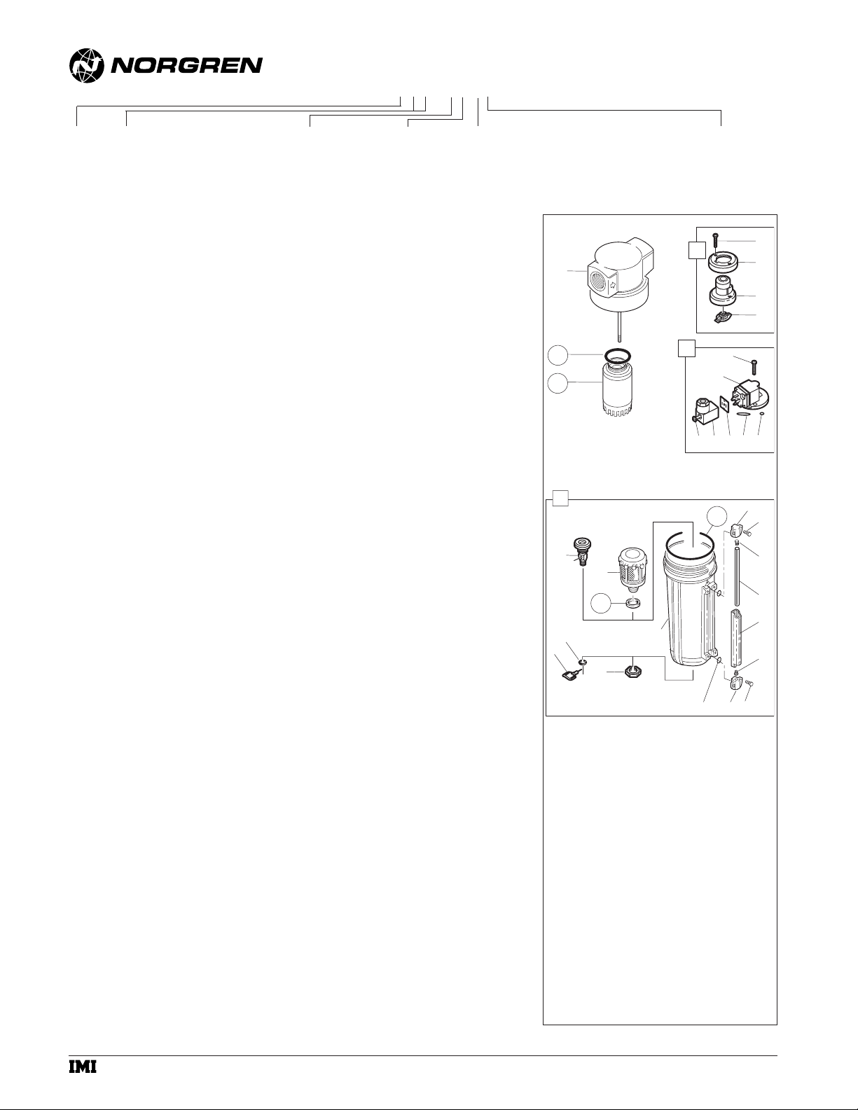
DISASSEMBLY
1. Filter can be disassembled without removal from air line.
2. Shut off inlet pressure. Reduce pressure in inlet and outlet
lines to zero.
3. Disassemble in general accordance with the item numbers
on exploded view.Do not remove the drains or the service
indicators (1, 6) unless replacement is necessary. Remove
and replace only if they malfunction
CLEANING
1. Element (28) cannot be cleaned. Clean mechanical
indicator lens (3) with warm water only. Clean electrical
indicator (6) with dry, clean cloth. Clean other parts with
warm water and soap.
2. Rinse and dry parts. Blow out internal passages in body
(30) with clean, dry compressed air.
3. Inspect parts. Replace those found to be damaged.
ASSEMBLY
1. Lubricate o-rings with o-ring grease.
2 If the 1/4 turn manual drain (14, 15, 16 ) was removed,
lubricate the portion of the drain body (14) that contacts
the bowl, and the hole in the manual drain body that
accommodates the stem of drain valve (15) with o-ring
grease. Press body (14, ) thru hole from inside of bowl.
Place retainer o-ring (16) over body (14) and position in
groove. Press drain valve (15) thru hole in body (14).
3. Assemble the liquid indicator parts (20, 21, 22, 23, 24, 25)
to bowl. Apply a 0,9 to 1,8 kg (2 to 4 pound) clamping
force to upper and lower brackets (21) to pull brackets
together. Tighten screws (20) to 0,9 to 1,1 N-m (8 to 10
inch-pounds).
4. Assemble filter as shown on the exploded view. Arrows on
indicator (3, 8) and body (30) must point in same
direction.
5. Torque Table Torque in N-m (Inch-Pounds)
2, 7 (Screw) 2,8 to 3,9 (25 to 35)
18 (Nut) 2,3 to 2,8 (20 to 25)
28 (Element) 5 to 6 (45 to 55)
6. Turn bowl (27) into body until arrowhead on bowl is
aligned with or to the right of the arrowhead on the body.
CAUTION
Water vapor will pass through these units and could
condense into liquid form downstream as air temperature
drops. Install an air dryer if water condensation could have a
detrimental effect on the application.
WARNING
These products are intended for use in industrial
compressed air systems only. Do not use these products
where pressures and temperatures can exceed those listed
under Technical Data.
Before using these products with fluids other than air, for
nonindustrial applications, or for life-support systems consult
Norgren.
TECHNICAL DATA
Fluid: Compressed air
Maximum pressure: 17 bar (250 psig)
Operating temperature:* -34° to +65°C (-30° to +150°F)
* Air supply must be dry enough to avoid ice formation at
temperatures below +2°C (+35°F)
Particle removal: Down to 0.01 µm
Air quality: Within ISO 8573-1, Class 1 (particulates)
and Class 2 (oil content)
Maximum remaining oil content in outlet air: 0,01ppm
at +20°C (+70°F) with an inlet oil concentration of
17 ppm.
Maximum flow at 6,3 bar (90 psig) inlet pressure to
maintain stated oil removal performance:
3/4" ports: 42 dm
3
/s (90 scfm)
1" ports: 59 dm
3
/s (125 scfm)
1 1/4" ports: 59 dm
3
/s (125 scfm)
Nominal bowl size: 1 litre (1 quart US)
Drain connection: 1/8" pipe thread
Automatic drain operating conditions:
Minimum pressure: 0,7 bar (10 psig).
Drain opens when bowl pressure drops below 0,2 bar
(3 psig).
Minimum air flow required to close drain: 1 dm
3
/s
(2 scfm)
Materials:
Body: Aluminum
Bowl: Aluminum
Bowl sight glass: Pyrex
Elastomers: Neoprene and nitrile
Filter element: Synthetic fiber and polyurethane foam
REPLACEMENT ITEMS
Service kit
(includes items circled on exploded view)
...5351-04
Liquid level lens kit (20, 22 thru 26)........................2273-22
Manual drain (14, 15, 16) ..........................................619-50
Automatic drain (17, 18, 19)....................................3000-18
Mechanical service Indicator (1)..............................5797-50
Electrical service Indicator (6) ...............................4020-51R
INSTALLATION
1. Shut-off air pressure. Install filter in air line -
● vertically (bowl down),
● with air flow in direction of arrow on body,
● upstream of regulators, lubricators, and cycling
valves,
● as close as possible to the air supply when used as a
main line filter,
● as close as possible to the device being serviced
when used as a final filter.
2. Connect piping to proper ports using pipe thread sealant
on male threads only. Do not allow sealant to enter
interior of unit.
3. Turn bowl (27) into body until arrowhead on bowl is
aligned with or to the right of the arrowhead on the body
4. Flexible tube with 3mm (0.125") minimum I.D. can be
connected to the automatic drain. Avoid restrictions in
the tube.
5. Install a Norgren general purpose filter with a 5 µm
element upstream of the oil removal filter to obtain
maximum element service life.
SERVICING
1. Open manual drain to expel accumulated liquids. Keep
liquids below element (28).
2. Replace filter element when pressure drop across
element exceeds 0,7 bar (10 psig). The mechanical
service indicator shows approximately full red and the
optional electrical service indicator provides an electrical
output when pressure drop across element reaches 0,7
bar (10 psig).
© Norgren 2001
IM-341.105
(5/01)
Oil Removal Filter
F46 - ★★★ - ★★★★
Thread Form
A....PTF
B....ISO Rc taper
G....ISO G parallel
Port
6....3/4"
8....1"
A....1-1/4"
Bowl
D...1 litre (1 quart U.S.) metal with sight glass
M ..1 litre (1 quart U.S.) metal without sight glass
Drain
A....Automatic
M...Manual, 1/4 turn
Element
0....Coalescing
Service Indicator
00..Without
01..With mechanical indicator
04..With electrical service indicator
* See Norgren publication IM-900.920 for specifications and electrical wire connections of the optional electric service indicator.
1
30
29
28
13
14
17
19
16
15
18
6
8
1011
26
27
22
2
4
3
5
7
12
9A
9
21
20
23
24
25
23
20
21
a subsidiary of IMI plc
 Loading...