

Page 1
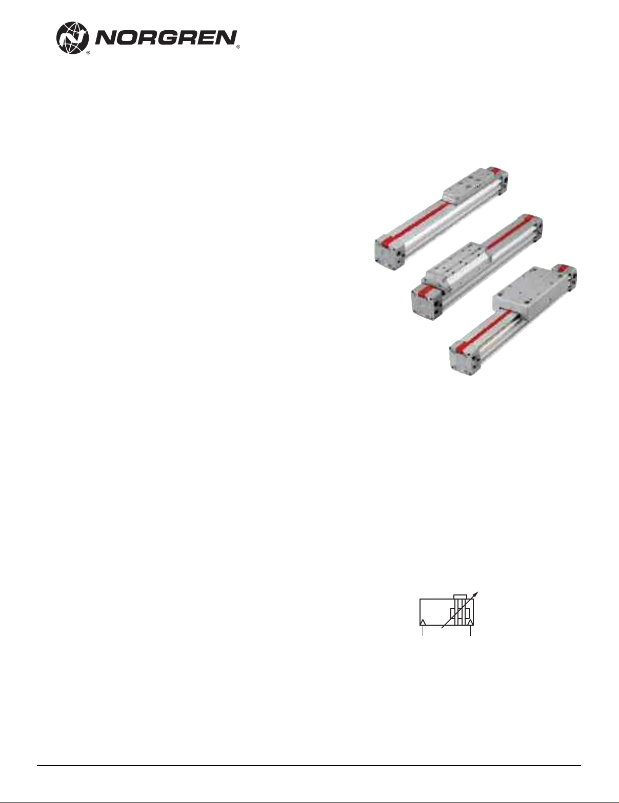
New lightweight design extrusion
with universal mounting grooves
Proven and patented sealing system
Dust protection as standard (Ø 25 to 63 mm)
Interchangeability with series C/46000
Technical data
Medium:
Compressed air. filtered.
lubricated or non-lubricated
Operation:
C/146000/M, C/146100/M, C/146200/M
Double acting with adjustable cushioning
and magnetic piston
Models:
C/146000 with internal guide
C/146100 with external adjustable guide
C/146200 with precision roller guide
Operating pressure:
14.5 to 116 psi (1 to 8 bar)
Operating temperature:
-22°F to 176°F (-30°C to +80°C) max.
(consult our Technical Service for use below 36°F [+2°C])
Cylinder diameter:
16, 20, 25, 32, 40, 50, 63, 80 mm
Max strokes:
Ø 16 to 40 mm: 27.9' (8500 mm)
Ø 50 and 63 mm: 26.2' (8000 mm)
Ø 80 mm: 18' (5500 mm)
C/146000, C/146100, C/146200
INTRA
L
Ordering example
see page 2
Mountings and switches
see page 3 & 4
Cylinder with linear position sensor
C/146000/F1
see page 2 & 20
®
LUS rodless cylinders
P
Magnetic piston
Double acting
Ø 16 to 80 mm
Materials:
End covers: aluminum diecast, molded plastic (Ø 16) and
anodized aluminum (Ø 20 & 80)
Yoke: anodized aluminum, molded plastic (Ø 16 & 20)
Carriage, closer & cover: aluminum diecast
Guiding bridge and profile barrel: anodized aluminum
Seal strip, wiper and piston seal: polyurethane
Cover strip: polyamide
Other seals: nitrile rubber
3/10
Our policy is one of continued research and development. We therefore reserve the right to amend,
without notice, the specifications given in this document.
Magnetic piston
N/us 1.6.009.01
Page 2
C/146000, C/146100, C/146200
ymbol Type (magnetic piston) Description Page
S
/146000/M With internal guide 7
C
C/146100/M With external adjustable guide 9, 10
/146200/M With precision roller guide (ø 25
C
/146200/PM With added caged ball linear motion guide (ø 25...63 mm) 15
C
C/146000/MC With alternative ports (ø 25...63 mm) 29
C/146100/MC
/146200/MC
C
C/146100/MD With external adjustable guide (ø 16
/146200/MD With precision roller guide (ø 25...63 mm) 14
C
/146000/L3 Active holding brake (ø 25
C
/146000/L4 Passive holding brake; (ø 25
C
C/146000/F1 With internal guide and linear position sensor (ø 32
C/146100/F1 With external adjustable guide 21
/146200/F1 With precision roller guide 21
C
ylinder with double carriages
C
Applying pressure activates the brake
The brake lining is pushed against a stainless steel strip.
o release, depressurize.
T
Applying pressure releases the brake. When the pressure
is released the brake lining is pushed against the stainless
teel strip by a spring loaded plate.
s
Electrical data of linear position sensor:
Operating voltage: 10 ... 30 V d.c.. resolution 16 bit.
Repeat accuracy 0.006 %. output 4 ... 20 mA. short-circuit protection
inearity 0.05 % of measuring range. protection class IP67
L
and linear position sensor (ø 32
nd linear position sensor (ø 32...63 mm)
a
3 mm) 13
...6
...
80 mm) 11, 12
3 mm) 16, 17
...6
3 mm) 18, 19
...6
...
63 mm) 20
...
63 mm)
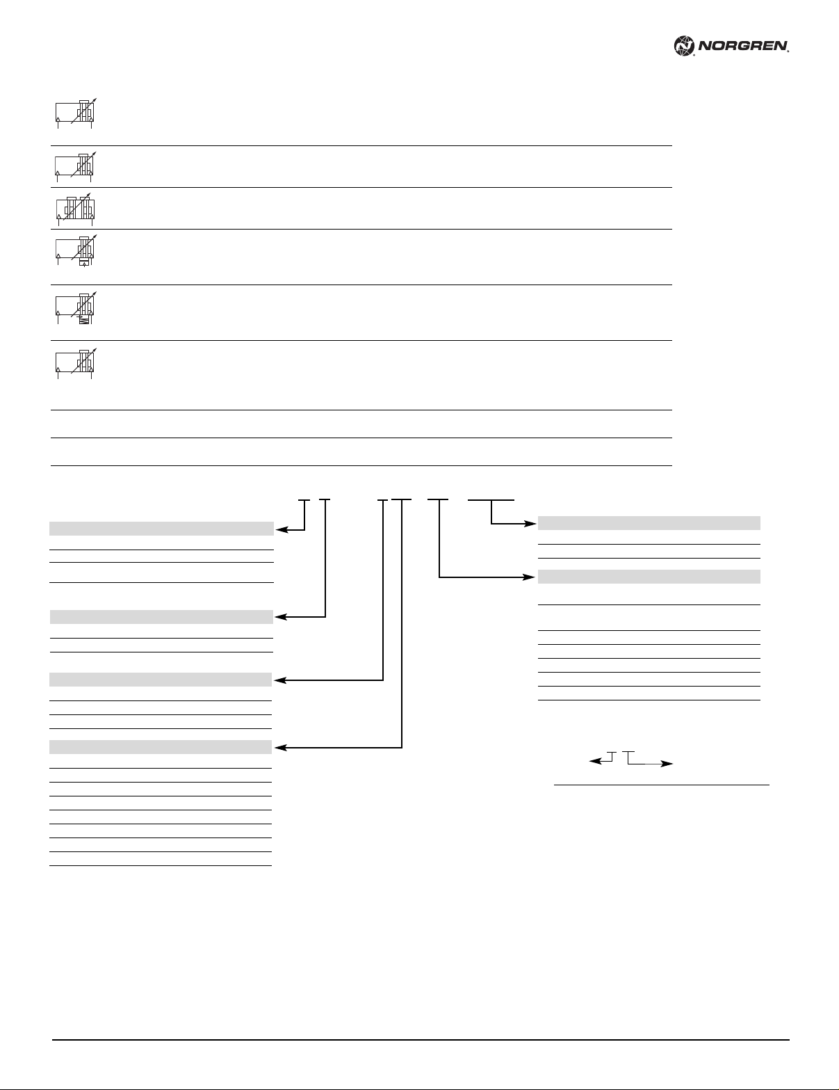
Options selector
Opitional finish Substitute
Standard non-anodized caps Blank
Black anodized caps and carriage A
Black anodized caps and carriage AS
with stainless steel hardware
Note: Options A and AS available only on metric port.
Ports Substitute
NPT ports (Ø 20 to 80 mm) C
Metric ports (Ø 16 to 80 mm) M
Guiding system Substitute
Internal 0
External 1
Roller 2
Cylinder Ø (mm) Substitute
16 16
20 20
25 25
32 32
40 40
50 50
63 63
80 80
Note: Disregard option positions not used.
For combinations of cylinder variants consult our Technical Service.
This options selector explains only the cylinder variants.
Additional variants/options are not possible.
C / 146 ˙˙˙ / MC / ˙˙˙˙
Ordering information
Cylinder
LINTRA
Ø 32 mm cylinder diameter and 10' (3000 mm) stroke length
with magnetic piston, and NPT ports.
Quote: C/146032/MC/120
®
cylinder with internal guiding system.
Strokes (on request)
Provide in Inches C version
Provide in Metric M version
Options (magnetic piston) STD. Substitute
Magnetic piston M
(standard on 16, 20, and 80 mm bores)
Alternative ports MC
(standard 25, 32, 40, 50, 63 mm bores)
Active brake (25 to 63 mm bores) L3
Passive brake (25 to 63 mm bores) L4
With added caged ball linear motion guide PM†
With linear position sensor (32 to 63 mm bores) F1
Double carriages * MD**
* For C/146100 & C/146200 only
** MD option available in 1461** External
and 1462** Roller guided carriage
C/146***/MD/****/****
Effective
stroke
1 Not available on 16, 20, 80 mm bores.
† Order PM option as 1462**
Distance between
carriage centers (inches)
1
N/us 1.6.009.02
Our policy is one of continued research and development. We therefore reserve the right to amend,
without notice, the specifications given in this document.
3/10
Page 3
C/146000, C/146100, C/146200
5
10
9
7
8
2
164
3
12
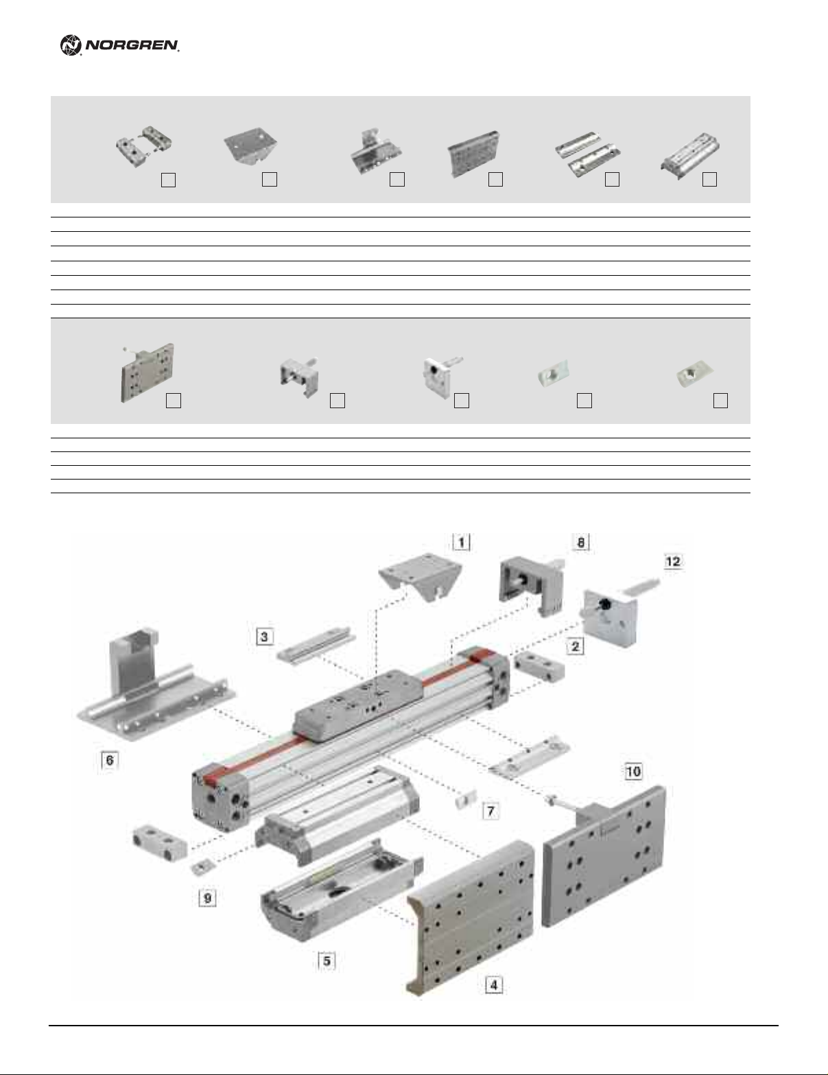
ountings
M
Type C Type S Type UV Type UW Type V Type W
Foot Mount Swinging Bridge Carriage Bracket Side Mounting Center Support Secondary
Ø mm Page 21 Page 23 Page 22 Page 24 Page 21 Page 24
6 QM/146016/21 QM/146016/37 QM/146016/34 - QM/146016/32 QM/146116/35
1
20 QM/146020/21 QM/146020/37 QM/146020/34 QM/146120/36 QM/146020/32 QM/146120/35
5 QM/146025/21 QM/146025/37 QM/146025/34 QM/146125/36 QM/146025/32 QM/146125/35
2
2 QM/146032/21 QM/146032/37 QM/146032/34 QM/146132/36 QM/146032/32 QM/146132/35
3
40 QM/146040/21 QM/146032/37 QM/146040/34 QM/146140/36 QM/146040/32 QM/146140/35
50 QM/146050/21 QM/146050/37 QM/146050/34 QM/146150/36 QM/146050/32 QM/146150/35
3 QM/146063/21 QM/146050/37 QM/146063/34 QM/146163/36 QM/146063/32 QM/146163/35
6
80 QM/146080/21 QM/146080/37 QM/146080/34 - QM/146080/32 QM/146180/35
Ø mm Page 16 Page 24 Page 25 Page 22 Page 22
5 QM/146225/P/70 QM/146125/75 QM/146125/67 M/P74065 M/P74065
2
32 QM/146232/P/70 QM/146132/75 QM/146132/67 M/P74065 M/P74065
40 QM/146240/P/70 QM/146140/75 QM/146140/67 M/P74065 M/P74066
50 QM/146250/P/70 – QM/146150/67 M/P74065 M/P41858
63 QM/146263/P/70 – QM/146163/67 M/P74065 M/P41858
Assembly kit for caged ball Adjustable stop Assembly kit for Groove key for Groove key for
linear motion guide shock absorbers profile barrel guiding bridge
late Carriage
P
3/10
Our policy is one of continued research and development. We therefore reserve the right to amend,
without notice, the specifications given in this document.
N/us 1.6.009.03
Page 4
C/146000, C/146100, C/146200
18 (8)
2204 (1000)
lb. (kg)
inches /s
(m / s)
Ø16
Ø20
Ø25
Ø32
Ø40
Ø50
Ø63
Ø80
1763 (800)
1300 (600)
8
82 (400)
441 (200)
1
76 (80)
132 (60)
88 (40)
44 (20)
22 (10)
13 (6)
8.8 (4)
4.4 (2)
2.2 (1)
16”
(0.4)
31”
(0.8)
47”
(1.2)
63”
(1.6)
79”
(2.0)
V
inches (mm)
19.7’
(6000)
16.4’
(5000)
13’
(4000)
9.8’
(3000)
6.5’
(2000)
3.2’
(1000)
0
2
0.04” (1)
0.004” (0.1)
0.02” (0.4)
ft.
(mm)
f
0.08” (2)
0.04
(0.9)
72”
(1830)
inches (mm)
f1= 0.04” (1 mm)
2248
(10000)
1124
(5000)
224
(1000)
112
(500)
22.5
(100)
2.25
(10)
0.22
(1)
39”
(1000)
0
6.6’
(2000)
9.8’
(3000)
13’
(4000)
16.4’
(5000)
19.6’
(6000)
Ø80
Ø63
Ø50
Ø40
Ø32
Ø25
Ø20
Ø16
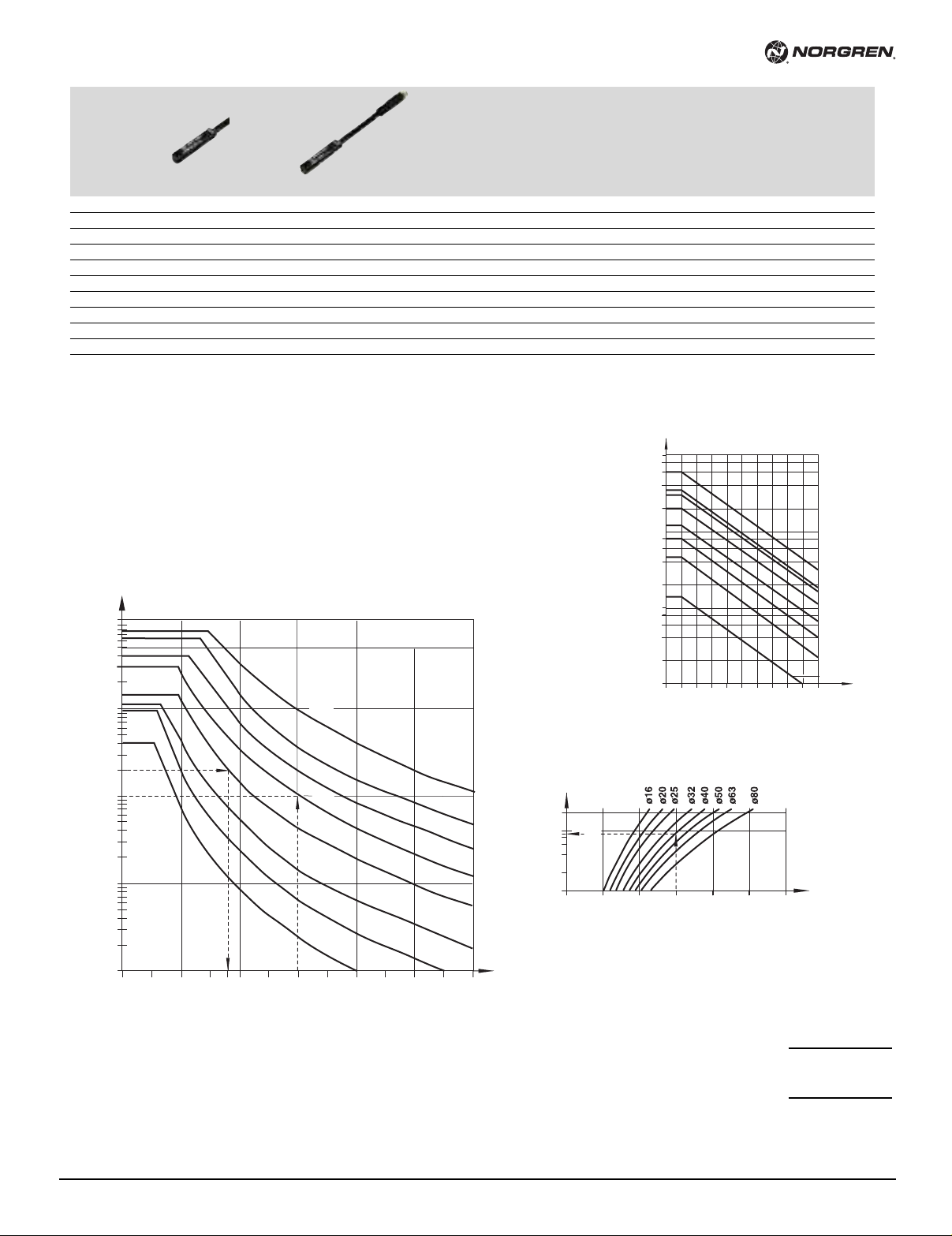
Switches
With cable With connector (M8x1)
able Cable with
C
Type Voltage Current Temperature LED Features Connector Cable connector
Reed Solid state V AC V DC max. °F length type straight Datasheet
/50/LSU/*V – 10 to 240 10 to 170 180 mA -4 to +176 •– 8', 33' PVC 2 x 0.25 – N/en 4.3.005
M
/50/LSU/5U – 10 to 240 10 to 170 180 mA -4 to +176 •– 16' PUR 2 x 0.25 – N/en 4.3.005
M
TM/50/RAU/2S – 10 to 240 10 to 170 180 mA -4 to +302 –– 6.5' Silicone 2 x 0.25 – N/en 4.3.005
M/50/RAC/5V – 10 to 240 10 to 170 180 mA -4 to +176 – Changeover 16' PVC 3 x 0.25 – N/en 4.3.005
/50/LSU/CP – 10 to 60 10 to 75 180 mA -4 to +176 • Plug M8x1 16' PVC 3 x 0.25 M/P73001/5 N/en 4.3.005
M
–
M/50/EAP/*V – 10 to 30 150 mA -4 to +176 • PNP 8', 33' PVC 3 x 0.25 – N/en 4.3.007
– M/50/EAP/CP – 10 to 30 150 mA -4 to +176 • PNP, plug M8x1 16' PVC 3 x 0.25 M/P73001/5 N/en 4.3.007
– M/50/EAP/CC – 10 to 30 150 mA -4 to +176 • PNP, plug M12x1 16' PVC 3 x 0.25 M/P34614/5 N/en 4.3.007
–
M/50/EAN/*V – 10 to 30 150 mA -4 to +176 • NPN 8', 33' PVC 3 x 0.25 – N/en 4.3.007
– M/50/EAN/CP – 10 to 30 150 mA -4 to +176 • NPN, plug M8x1 16' PVC 3 x 0.25 M/P73001/5 N/en 4.3.007
Please insert cable length
*
Cushioning Performance
The dynamic energy of a LINTRA®cylinder is caused by direct or partial external loads
which must be absorbed by pneumatic cushioning.
The cushioning ability depends to a large extent on the pneumatic circuit (e. g. counter
pressure, pre-exhaust). The values given in the diagram were tested with an operation
pressure of 87 psi (6 bar) using a 5/2 control valve. When installed horizontally, depending
upon the speed, dynamic energy can be absorbed by the cylinder. Whenever the values
given in the diagram are exceeded, the transported mass must be cushioned by additional
shock absorbers. These have to be located at the center of gravity of the mass.
Cylinder deflection
Deflection due to external forces
Example:
Cylinder Ø 32 mm, stroke length 11' (3500 mm), external load
Our policy is one of continued research and development. We therefore reserve the right to amend,
without notice, the specifications given in this document.
45 lbf. (200 N) and a deflection about 0.04 (1 mm).
Maximum distance between supports = 6' (1830 mm) (see diagrams).
Therefore an additional support is required.
N/us 1.6.009.04
Support length
Deflection due to cylinder weight
Example:
Cylinder Ø 40 mm. external force 40 lbf (180 N),
distance between supports 10' (3000 mm)
Required: total deflection
1. Deflection due to external force (f1)
see Diagram 1 (1mm/100 N) · 40 lbf (180 N)
2. Deflection due to cylinder weight diagram 2
Total deflection:
Max. permitted deflection (f1 + f2)
A deflection of more than 0.12" (3 mm)
is not permitted.
Support length
0.07"(1.8 mm)
+ 0.04"(0.9 mm)
0.2" (2.7 mm)
< 0.04"(1 mm)
39"(1000 mm) Stroke
3/10
Page 5
C/146000, C/146100, C/146200
Theoretical forces, air consumption, cushioning length, holding forces
ylinder Theoretical forces lbf (N) Air consumption ft
C
mm at 87 psi (6 bar) of stroke at 87 psi (6 bar) inches (mm) active (L3) at 87 psi (6 bar) passive (L4)
Ø
16 27 (120) 0.001 (0.014) 0.5 (12) ––
20 42 (188) 0.002 (0.022) 1 (26) ––
5 66 (294) 0.003 (0.035) 1 (26) 112 (5000 50 (220)
2
2 108 (482) 0.005 (0.056) 1.4 (35) 202 (900) 84 (375)
3
40 170 (754) 0.008 (0.088) 2 (50) 337 (1500) 141 (630)
0 265 (1178) 0.012 (0.137) 2.3 (60) 562 (2500) 225 (1000)
5
3 420 (1870) 0.02 (0.218) 2.8 (70) 899 (4000) 371 (1650)
6
80 678 (3016) 0.03 (0.350) 3 (75) – –
3
in. (l/cm) Cushioning length Holding forces lbf. (N) of brake (on dry braking surface)
/
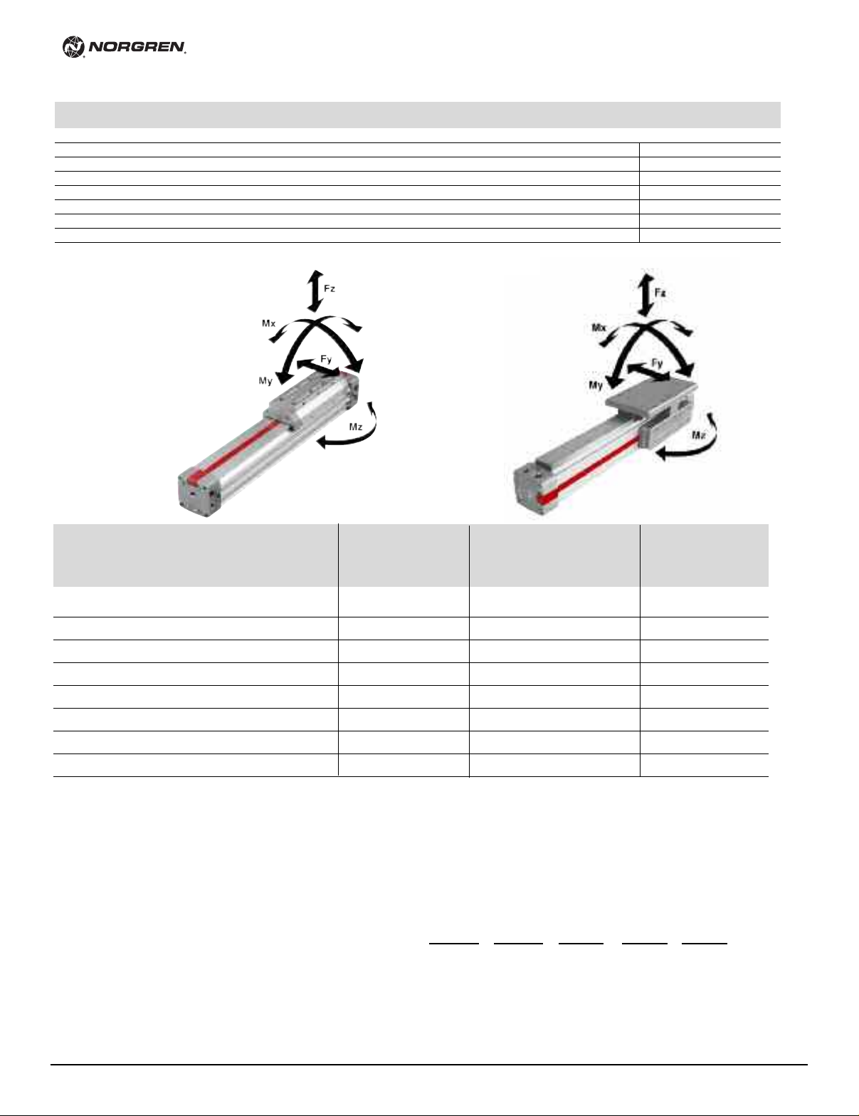
C/146000, C/146100, C/146200
Internal guide External adjustable guide Precision roller guide Added caged ball linear
Fy Fz Mx My Mz Fy, Fz Mx My, Mz Fy Fz Mx My, Mz Fy, Fz Mx My, Mz
Ø mm (N) (N) (Nm) (Nm) (Nm) (N) (Nm) (Nm) (N) (N) (Nm) (Nm) (N) (Nm) (Nm)
16 9 27 2.7 33.6 9.7 45 17.7 48.7 – – – – – – –
20 20 63 8.0 106.2 31.9 106 53.1 159.3 – – – – – – –
25 28 87 13.3 168.2 49.6 133 79.7 247.8 133 266 115.1 371.7 450 283 1770
32 37 113 26.6 292.1 88.5 176 150.5 380.6 176 351 221.3 566.5 899 566 3540
40 74 223 57.5 743.5 212.4 360 345.2 973.6 338 676 513.4 1416.2 899 566 3540
50 99 297 97.4 1062.1 309.8 450 575.3 1416.2 450 901 858.6 2124.3 1798 1593 7080
63 155 450 177.0 2124.3 619.6 721 1062.1 3097.9 721 1441 1593.2 4602.6 1798 1593 7966
80 176 518 239.0 3186.4 885.1 878 1593.2 4602.6
Loading values applicable to a speed of √0.2 m/s. Maximum working life is normally reached below a speed of 1 m/s.
* The forces and moments refers to the center of the guide. They must not be exceeded in dynamic applications.
lbf. lbf. lbf in. lbf in. lbf in. lbf. lbf in. lbf in. lbf. lbf. lbf in. lbf in. lbf. lbf in. lbf in.
(40) (120) (0.3) (3.8) (1.1) (200) (2) (5.5) – – – – – – –
(90) (280) (0.9) (12) (3.6) (470) (6) (18) –––––––
(125) (385) (1.5) (19) (5.6) (590) (9) (28) (590) (1180) (13) (42) (2000) (32) (200)
(165) (500) (3) (33) (10) (780) (17) (43) (780) (1560) (25) (64) (4000) (64) (400)
(330) (990) (6.5) (84) (24) (1600) (39) (110) (1500) (3000) (58) (160) (4000) (64) (400)
(440) (1320) (11) (120) (35) (2000) (65) (160) (2000) (4000) (97) (240) (8000) (180) (800)
(690) (2000) (20) (240) (70) (3200) (120) (350) (3200) (6400) (180) (520) (8000) (180) (900)
(780) (2300) (27) (360) (100) (3900) (180) (520) –––––––
C/146000 C/146100 C/146200 motion guide C/146200/P
C/146200/P
Loading values for LINTRA®cylinders
with double carriages
The values given in the table below show the single forces in the
directions Fy and Fz and the maximum moments Mx, My and Mz.
All values are applicable only for speeds of max. 0.2 m/s.
A requirement for using these values is a constant movement (no
jerking) of the mass over the whole stroke length of the cylinder.
The reference point from which the moments for all cylinders should
be calculated is the center line of the pistons.
3/10
Our policy is one of continued research and development. We therefore reserve the right to amend,
without notice, the specifications given in this document.
®
When a LINTRA
cylinder has to take several loads and moments. an
additional calculation is necessary using this formula:
Mx
Mx max My max Mz max Fy max Fz max
My
+
Mz
+
Fy
+
Fz
+
N/us 1.6.009.05
<_
1
Page 6
C/146000, C/146100, C/146200
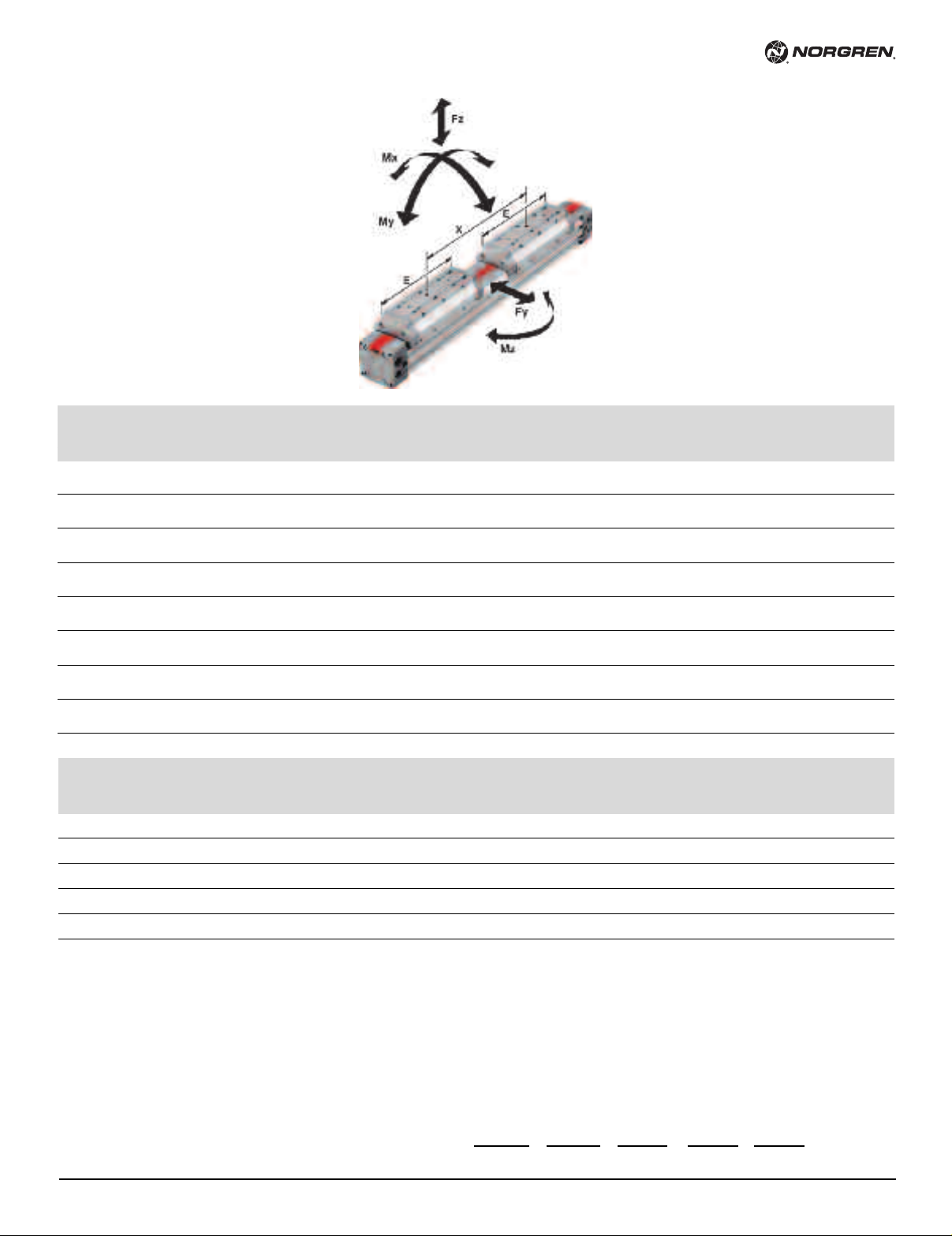
/146100/MD
C
External adjustable guide. C/146100/MD
y. Fz Mx My. Mz (Nm) x=4" x=6" x=8" x=10" x=12" x=14" x=16" x=18" x=20"
F
mm lbf (N) lbf in (Nm) x min.=E (100 mm) (150 mm) (200 mm) (250 mm) (300 mm) (350 mm) (400 mm) (450 mm) (500 mm)
Ø
6 90 36 120 156 204 252 312 360 420 480 528 588
1
400) (4) (14) (17) (23) (29) (35) (41) (48) (54) (60) (66)
(
0 211.33 1296 6768 – 8496 10512 1272 1236 1404 1572 1740 1920
2
(940) (12) (64) – (80) (99) (119) (139) (158) (178) (197) (217)
25 265.29 156 852 – 936 1164 1368 1596 1812 2040 2256 2472
(1180) (18) (96) – (106) (131) (155) (180) (205) (230) (255) (279)
32 350.72 300 1368 –– 1596 1884 2172 2460 2748 3036 3324
(1560) (34) (155) ––(181) (213) (246) (278) (310) (343) (375)
40 674.46 696 3480 –– –3852 4392 4932 5472 6012 6552
(3000) (78) (393) –––(435) (496) (557) (618) (679) (740)
50 899.28 1152 4044 –– –4044 4584 5124 5652 6192 6732
(4000) (130) (457) –––(457) (518) (579) (639) (700) (761)
63 1438.85 2124 11328 –––– –12036 13272 14424 15660
(6400) (240) (1280) –– –– –(1360) (1500) (1630) (1770)
80 1753.60 3192 16908 –––– ––17172 18672 20088
(7800) (360) (1910) –– –– ––(1940) (2110) (2270)
bf in (Nm) lbf in (Nm) lbf in (Nm) lbf in (Nm) lbf in (Nm) lbf in (Nm) lbf in (Nm) lbf in (Nm) lbf in (Nm) lbf in (Nm)
l
Precision roller guide C/146200/MD
Ø mm lbf (N) lbf in (Nm) x min.=E (100 mm) (150 mm) (200 mm) (250 mm) (300 mm) (350 mm) (400 mm) (450 mm) (500 mm)
25 265 228 1104 – 1224 1500 1788 2076 2364 2652 2940 3216
32 351 444 1788 –– 2076 2448 2832 3192 3564 3948 4320
40 674 1032 4524 –– –5004 5712 6408 7104 7812 8520
50 899 1716 5256 –– –5256 5952 6660 7356 8052 8748
63 1439 3192 14724 –––––15648 16368 18756 20364
Loading values applicable to a speed of √0.2 m/s. Maximum working life is normally reached below a speed of 1 m/s.
* The forces and moments refers to the center of the guide. They must not be exceeded in dynamic applications.
Fy. Fz Mx My. Mz x=4" x=6" x=8" x=10" x=12" x=14" x=16" x=18" x=20"
lbf in (Nm) lbf in (Nm) lbf in (Nm) lbf in (Nm) lbf in (Nm) lbf in (Nm) lbf in (Nm) lbf in (Nm) lbf in (Nm) lbf in (Nm)
(1180) (26) (125) – (138) (170) (202) (234) (267) (299) (332) (363)
(1560) (50) (202) –– (235) (277) (320) (361) (403) (446) (488)
(3000) (116) (511) –– –(566) (645) (724) (803) (883) (962)
(4000) (194) (594) –– –(594) (673) (753) (831) (910) (989)
(6400) (360) (1664) –––––(1768) (1850) (2119) (2301)
Loading values for LINTRA®cylinders
with double carriages
The values given in the table below show the single forces in the
directions Fy and Fz and the maximum moments Mx, My and Mz.
All values are applicable only for speeds of max. 0.2 m/s.
A requirement for using these values is a constant movement (no
jerking) of the mass over the whole stroke length of the cylinder.
The reference point from which the moments for all cylinders should
be calculated is the center line of the pistons.
N/us 1.6.009.06
Our policy is one of continued research and development. We therefore reserve the right to amend,
without notice, the specifications given in this document.
For speeds up to 2 m/s please use our calculation program
®
LINTRA
PNEUCALC. It is available upon request.
When a LINTRA®cylinder has to take several loads and moments. an
additional calculation is necessary using this formula:
Mx
Mx max My max Mz max Fy max Fz max
My
+
Mz
+
Fy
+
Fz
+
<_
1
3/10
Page 7
AE
Z
D
C
B
A
Stroke
2 x A + Stroke
R 1
S
S 1
AC
S
N
AG
M
R
K
G
F
E
B
A
T
J
Y
A - B
O 1
ø 20 mm
O P
1
2
O 1
O
P
2
ø 16 mm
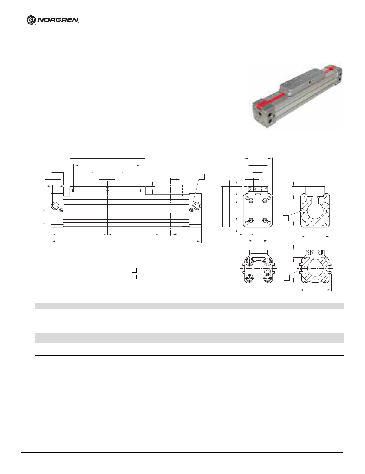
C/146000 – cylinder with internal guide (ø 20 mm)
M/146000 – cylinder with internal guide (ø 16 and 20 mm)
C/146000, C/146100, C/146200
Cylinder with internal guide
C/146000 cylinder ø 20 to 80 mm
M/146000 cylinder ø 16 to 80 mm
1
Cushion screw
2
M/50 – switches and groove key can
be mounted flush with the profile
Type Ø A AC AE AG BCDEFGJØ K
M/146016/... 16 2.46 0.28 1.50 0.31 0.69 0.31 M5 3.15 2.36 – 0.10 0.12
(62.5) (7) (38) (8) (17.5) (8) M5 (80) (60) – (2.5) (3)
C/146020/... 20 3.34 0.55 2.13 0.71 0.91 0.31 1/8 NPT 4.33 3.15 1.57 0.14 0.17
Type Ø MNOO 1 PRR 1 S S 1 TYZWeight Weight
M/146016/... 16 0.71 M3 0.98 1.26 0.47 1.06 1.22 0.63 0.22 M3-5* 0.16 0.65 0.35 lbs.. 0.22 lbs.
C/146020/... 20 1.06 M5 1.26 1.50 0.73 1.57 1.57 1.26 0.16 M5-12* 0.47 0.81 1.10 lbs. 0.33 lbs.
* deep
(85) (14) (54) (18) (23) (8) G1/8 (110) (80) (40) (3.5) (4.2)
(18) M3 (25) (32) (12) (27) (31) (16) (5.5) M3-5* (4) (16.5) (0.35 kg) (0.10 kg)
(27) M5 (32) (38) (18.5) (40) (40) (32) (4) M5-12* (12) 20.5 (0.50 kg) (0.15 kg)
at 0 mm per 100 mm
D7
3/10
Our policy is one of continued research and development. We therefore reserve the right to amend,
without notice, the specifications given in this document.
N/us 1.6.009.07
Page 8
C/146000, C/146100, C/146200
A-A
A
E E1 M
S
6,5
R
O1
T
N
B
D
C
J
AC
AE
O P
CA
5,3
Y
5
WZ
K
Stroke
2 x A + Stroke
A
A
1
2
G
F
AG
3
4
6
5
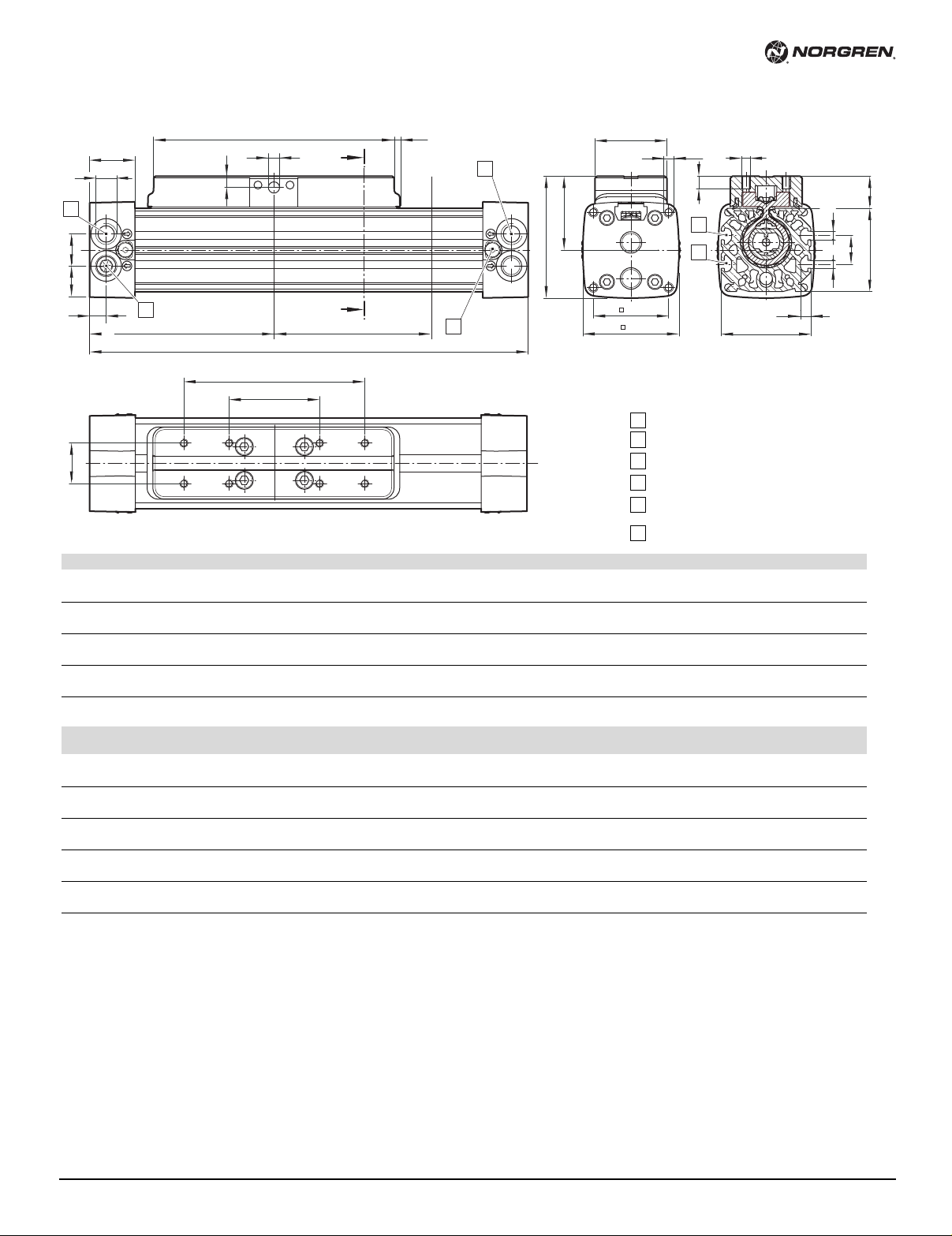
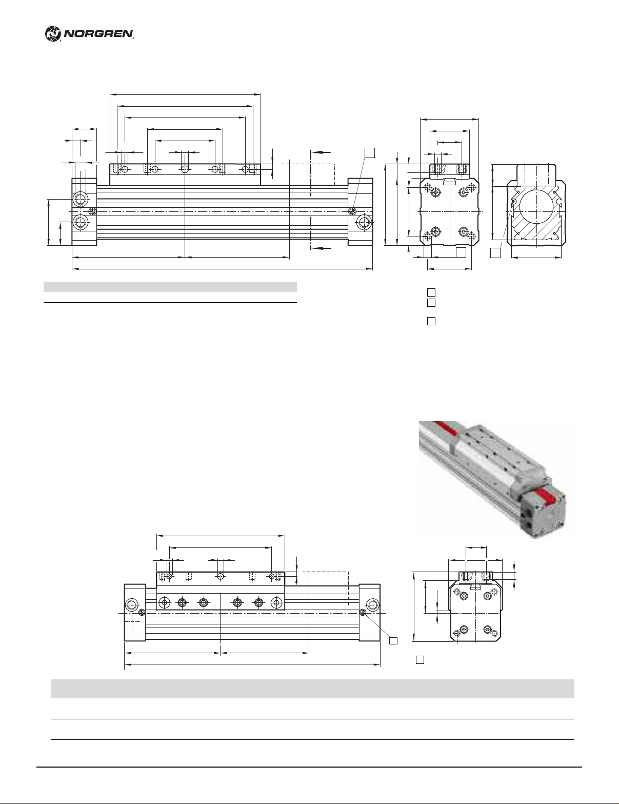
C/146000 – cylinder with internal guide (ø 25 ... 63 mm)
Type Ø A AC AE AG BCCA DEE1 FGJØ K
C/146025/... 25 3.94 1.42 2.20 0.78 0.91 0.33 – 1/8 NPT 5.12 – 3.54 1.77 0.19 0.20
C/146032/... 32 4.72 1.81 2.99 0.98 1.12 0.41 0.71 1/4 NPT 6.30 0.14 4.72 2.36 0.28 0.28
C/146040/... 40 5.91 2.07 3.54 0.98 1.12 0.45 0.71 1/4 NPT 8.46 – 6.30 3.15 0.28 0.28
C/146050/... 50 7.09 2.58 4.33 0.98 1.50 0.59 0.94 3/8 NPT 9.84 – 7.48 3.74 0.37 0.35
C/146063/... 63 8.46 3.25 4.92 0.98 1.50 0.67 – 1/2 NPT 12.60 – 9.45 4.72 0.37 0.35
Type Ø MNOO 1 PR S T WYZ Weight Weight
C/146025/... 25 1.26 M5 1.57 1.81 0.63 1.89 1.46 M5-13* 0.63 0.28 0.63 1.5 lbs. 0.55 lbs.
C/146032/... 32 1.77 M5 2.05 2.20 0.79 2.36 1.85 M6-17* 0.79 0.31 0.79 3 lbs. 0.66 lbs.
C/146040/... 40 1.77 M6 2.56 2.68 0.79 2.93 2.28 M8-20* 0.98 0.31 0.98 5.5 lbs. 0.93 lbs.
C/146050/... 50 1.97 M8 3.15 3.31 1.00 3.50 2.76 M8-20* 1.18 0.43 1.16 9.7 lbs. 1.3 lbs.
C/146063/... 63 1.97 M8 3.74 3.82 0.98 4.13 3.31 M10-24* 1.38 0.43 1.38 15.2 lbs. 2 lbs.
* deep
(100) (36) (56) (20) (23) (8.5) – G1/8 (130) – (90) (45) (4.7) (5)
(120) (46) (76) (25) (28.5) (10.5) (18) G1/4 (160) (3.5) (120) (60) (7) (7)
(150) (52.5) (90) (25) (28.5) (11.5) (18) G1/4 (215) – (160) (80) (7) (7)
(180) (65.5) (110) (25) (38) (15) (24) G3/8 (250) – (190) (95) (9.5) (9)
(215) (82.5) (125) (25) (38) (17) – G1/2 (320) – (240) (120) (9.5) (9)
troke
S
#
ushion screw
C
1
2
Main port
Main port
3
4
One alternative port with plug inserted
M/50 – switches and groove key can
5
e mounted flush with the profile
b
6
or groove key only
F
at 0 mm per 100 mm
(32) M5 (40) (46) (16) (48) (37) M5-13* (16) (7) (16) 0.7 kg 0.25 kg
(45) M5 (52) (56) (20) (60) (47) M6-17* (20) (8) (20) 1.40 kg 0.30 kg
(45) M6 (65) (68) (20) (74.5) (58) M8-20* (25) (8) (25) 2.50 kg 0.42 kg
(50) M8 (80) (84) (25.5) (89) (70) M8-20* (30) (11) (29.5) 4.40 kg 0.62 kg
(50) M8 (95) (97) (25) (105) (84) M10-24* (35) (11) (35) 6.90 kg 0.9 kg
D7
N/us 1.6.009.08
Our policy is one of continued research and development. We therefore reserve the right to amend,
without notice, the specifications given in this document.
3/10
Page 9
C/146080 – cylinder with internal guide (ø 80 mm)
6.06 (154)
3.54 (90)
1.57 (40)
1/2 NPT
G
1/2
0
.67 (17)
1
.77 (45)
10.24 (260) Stroke
2
x 10.24 (260) + Stroke
5.12 (130)
3.94 (100)
0.59 (15)
0.94 (24)
3.94 (100)
M
10
0
.98 (25)
2.0 (50)
5.12 (130)
4.72 (120)
ø
0.47 (12)
E7
5
.91 (150)
(11)
9
.45 (240)
11.81 (300)
1
5.35 (390)
B
A
A
- B
M
12
0.35 (9)
4
.72 (120)
4.72 (120) 1.14 (29)
0.59 (15)
1
2
3
AE
R 2
AD
Y
K LU
AB
E
J
A
Stroke
2 x A + Stroke
1
ED
C/146000, C/146100, C/146200
Type Ø Weight at 0 mm Weight per 100 mm
/146080/ 80 29 lbs. (13.20 kg) 3 lbs. (1.50 kg)
C
Cylinder with external adjustable guide
C/146100 – cylinder with external guide (ø 20 mm)
M/146100 – cylinder with external guide (ø 16 & 20 mm)
1
Cushion screw
2
M/50 – switches and groove key can
e mounted flush with the profile
b
3
26 deep
C/146100 cylinder ø 20 to 80 mm
M/146100 cylinder ø 16 to 80 mm
Type Ø A AB AE AD EMJØ K L R 2 UYWeight Weight
M/146116/... 16 2.46 – 1.50 0.30 3.15 0.71 ––1.22 0.73 – 0.20 0.31 oz. 0.22 lbs.
(62.5) – (38) (7.5) (80) (18) ––(31) (18.5) – (5) 0.18 kg 0.10 kg
C/146120/... 20 3.35 2.36 2.32 0.26 4.33 1.06 0.30 0.22 1.65 0.94 0.22 0.47 1.3 oz. 0.33 lbs.
(85) (60) (59) (6.5) (110) (27) (7.5) (5.5) (42) (24) (5.5) (12) 0.60 kg 0.15 kg
3/10
Our policy is one of continued research and development. We therefore reserve the right to amend,
without notice, the specifications given in this document.
1
Cushion screw
at 0 mm per 100 mm
N/us 1.6.009.09
Page 10

C/146000, C/146100, C/146200
E
A
EB
89
AF
AB
E
E1
A
2
x A + Stroke
Stroke
K
R2
AE
EF
Y
J
L
ED
E
C
D
1.50 (38)
3.19 (81)
5.12 (130)
6.50 (165)
10.24 (260) Stroke
2 x A + Stroke
0.47 (12) E70.43 (11)
9.45 (240)
15.35 (390)
0.39 (10)
0.98 (25)
4.72 (120)
0.98 (25)
1/2 NPT
(G1/2)
C/146100 – cylinder with external adjustable guide (ø 25 ... 63 mm)
8
Center bore Ø 6H7. 4 deep
9
Supplied complete with four groove keys
Type Ø A AB AE AF DEE1 EA EB ED EC EF J Ø K L R 2 Y Weight Weight
±0.05 at 0 mm per 100 mm
C/146125/.. 25 3.94 2.76 2.66 M5 1/8 NPT 5.12 – 1.97 4.02 1.26 0.79 1.34 0.20 0.22 2.05 – 0.37 1.7 lbs. 0.44 lbs.
(100) (70) (67.5) G1/8 (130) – (50) (102) (32) (20) (34) (5) (5.5) (52) – (9.5) 0.75kg 0.20 kg
C/146132/.. 32 4.72 3.54 3.23 M5 1/4 NPT 6.30 0.16 2.76 5.43 1.77 0.98 1.44 0.20 0.22 2.52 2.05 0.26 3.3 lbs. 0.66 lbs.
(120) (90) (82) G1/4 (160) (4) (70) (138) (45) (25) (36.5) (5) (5.5) (64) (52) (6.5) 1.50 kg 0.30 kg
C/146140/.. 40 5.91 4.72 3.84 M6 1/4 NPT 8.46 – 4.13 7.60 1.77 0.98 1.69 0.20 0.26 3.11 2.36 0.37 5.7 lbs. 0.93 lbs.
(150) (120) (97.5) G1/4 (215) – (105) (193) (45) (25) (43) (5) (6.6) (79) (60) (9.5) 2.60 kg 0.42 kg
C/146150/.. 50 7.09 6.30 4.59 M8 3/8 NPT 9.84 – 5.31 8.98 1.97 0.98 1.87 0.26 0.35 3.62 2.83 0.45 10 lbs. 1.4 lbs.
(180) (160) (116.5) G3/8 (250) – (135) (228) (50) (25) (47.5) (6.5) (9) (92) (72) (11.5) 4.50 kg 0.62 kg
C/146163/.. 63 8.46 7.48 5.39 M8 1/2 NPT 12.60 – 5.91 11.50 1.97 0.98 2.32 0.30 0.35 4.33 3.33 0.65 16 lbs. 2 lbs.
(215) (190) (137) G1/2 (320) – (150) (292) (50) (25) (59) (7.5) (9) (110) (84.5) (16.5) 7.20kg 0.90 kg
C/146180 – cylinder with external adjustable guide (ø 80 mm)
Type Ø Weight at 0 mm Weight per 100 mm
C/146180/ 80 29.5 lbs. (13.40 kg) 3.3 lbs. (1.50 kg)
N/us 1.6.009.010
Our policy is one of continued research and development. We therefore reserve the right to amend,
without notice, the specifications given in this document.
3/10
Page 11

C/146000, C/146100, C/146200
A
X
2 x A + X + Stroke
E
E
A
2 x A + X + Stroke
X
E1
Cylinder with external adjustable guide
and double carriages
C/146100 cylinder ø 20 to 80 mm
M/146100 cylinder ø 16 to 80 mm
C/146100/MD – cylinder with external adjustable guide and double carriages(ø 20 mm)
M/146100/MD – cylinder with external adjustable guide and double carriages(ø 16 and 20 mm)
Type ØA E X min. X max. Weight at 0 mm Weight per 100 mm
M/146116/D 16 2.46 3.15 3.15 19.69 0.44 lbs. 0.22 lbs.
C/146120/D 20 3.35 4.33 4.33 19.69 1.75 lbs. 0.33 lbs.
(62.5) (80) (80) (500) 0.20 kg 0.10 kg
(85) (110) (110) (500) 0.80 kg 0.15kg
C/146100/MD – cylinder with external adjustable guide and double carriages (ø 25 ... 63 mm)
Type ØA E E1 X min.=E* X max. Weight at 0 mm Weight per 100 mm
C/146125/MD 25 3.94 5.12 – 5.12 19.69 3.3 lbs. 0.44 lbs.
C/146132/MD 32 4.72 6.30 0.16 6.61 19.69 4.4 lbs. 0.66 lbs.
C/146140/MD 40 5.91 8.46 – 8.46 19.69 7 lbs. 0.93 lbs.
C/146150/MD 50 7.09 9.84 – 9.84 19.69 12 lbs. 1.4 lbs.
C/146163/MD 63 8.46 12.60 – 12.60 19.69 18.5 lbs. 2.2 lbs.
* For 32 mm bore X min = E + (2 x E1)
3/10
(100) (130) – (130) (500) 1.50 kg 0.20 kg
(120) (160) (4) (168) (500) 2.00 kg 0.30 kg
(150) (215) – (215) (500) 3.20 kg 0.42 kg
(180) (250) – (250) (500) 5.40 kg 0.62 kg
(215) (320) – (320) (500) 8.40 kg 1.00 kg
Our policy is one of continued research and development. We therefore reserve the right to amend,
without notice, the specifications given in this document.
N/us 1.6.009.011
Page 12

C/146000, C/146100, C/146200
2
60
2 x A + X + Stroke
X
C/146180/MD – cylinder with external adjustable guide and double carriages (ø 80 mm)
ype ØA X min. X max. Weight at 0 mm Weight per 100 mm
T
/146180/D 80 10.53 (260) 15.4 (390) 19.7 (500) 35 lbs. (15.90 kg) 3.3 lbs. (1.50 kg)
C
N/us 1.6.009.012
Our policy is one of continued research and development. We therefore reserve the right to amend,
without notice, the specifications given in this document.
3/10
Page 13

EA
CA
CB
8
9
E
A
2 x A + Stroke
CG
CC
CDCFCE
C
H
Stroke
(both sides)
D
Cylinder with precision roller guide
C/146200 – cylinder with precision roller guide (ø 25 to 63 mm)
C/146000, C/146100, C/146200
C/146200 cylinder ø 25 to 63 mm
For complete cylinder dimensions see page 10.
Type ØA CA CB CC CD CE CF CG CH DEEA Weight Weight
C/146225/... 25 3.94 1.77 3.54 M6-14* 1.42 1.65 2.60 2.36 3.35 1/8 NPT 5.91 2.76 3.3 lbs. 0.44 lbs.
C/146232/... 32 4.72 2.36 4.72 M8-16* 1.50 1.97 3.15 2.95 3.86 1/4 NPT 7.09 3.54 6 lbs. 0.88 lbs.
C/146240/... 40 5.91 3.15 5.91 M8-16* 1.65 2.26 3.74 3.62 4.65 1/4 NPT 8.46 4.53 10 lbs. 1 lbs.
C/146250/... 50 7.09 3.54 7.09 M10-20* 1.73 2.64 4.39 3.94 5.20 3/8 NPT 9.84 5.31 18 lbs. 2 lbs.
C/146263/... 63 8.46 4.72 9.45 M10-20* 1.85 2.93 5.00 4.33 5.51 1/2 NPT 12.60 7.87 28 lbs. 2.2 lbs.
*1 deep
(100) (45) (90) M6-14* (36) (42) (66) (60) (85) G1/8 (150) (70) 1.50 kg 0.20 kg
(120) (60) (120) M8-16* (38) (50) (80) (75) (98) G1/4 (180) (90) 2.80 kg 0.40 kg
(150) (80) (150) M8-16* (42) (57.5) (95) (92) (118) G1/4 (215) (115) 4.50 kg 0.45 kg
(180) (90) (180) M10-20* (44) (67) (111.5) (100) (132) G3/8 (250) (135) 8.20 kg 0.90 kg
(215) (120) (240) M10-20* (47) (74.5) (127) (110) (140) G1/2 (320) (200) 12.50 kg 1.00 kg
8
Center bore Ø 6H7. 4 deep
9
For lubrication
±0.05 at 0 mm per 100 mm
3/10
Our policy is one of continued research and development. We therefore reserve the right to amend,
without notice, the specifications given in this document.
N/us 1.6.009.013
Page 14

C/146000, C/146100, C/146200
E
X
A
2 x A + X + Stroke
Cylinder with precision roller guide
C/146200/MD – cylinder with precision roller guide and double carriages
and double carriages
C/146200/MD
ø 25 to 63 mm
Type ØA E X min. X max. Weight Weight
C/146225/MD/... 25 3.94 5.91 5.91 19.69 5.7 lbs. 0.44 lbs.
C/146232/MD/... 32 4.72 7.09 7.09 19.69 9.3 lbs. 0.88 lbs.
C/146240/MD/... 40 5.91 8.46 8.46 19.69 15 lbs. 1 lbs.
C/146250/MD/... 50 7.09 9.84 9.84 19.69 24 lbs. 2 lbs.
C/146263/MD/... 63 8.46 12.60 12.60 19.69 45 lbs. 2.2 lbs.
N/us 1.6.009.014
(100) (150) (150) (500) 2.60 kg 0.20 kg
(120) (180) (180) (500) 4.20 kg 0.40 kg
(150) (215) (215) (500) 7.00 kg 0.45 kg
(180) (250) (250) (500) 11.1 kg 0.90 kg
(215) (320) (320) (500) 20.6 kg 1.00 kg
Our policy is one of continued research and development. We therefore reserve the right to amend,
without notice, the specifications given in this document.
at 0 mm per 100 mm
3/10
Page 15

C/146000, C/146100, C/146200
A
FDFE
FB
FC
FN
FM
2 x A + Stroke
F
A
FG
FF
FK
F
L
FJFH
8
Stroke
8
Center bore ø 6 .4 deep
H7
Cylinder with added caged ball
linear motion guide
C/146200/PM
ø 25 to 63 mm
Type Ø A FA FB FC FD FE FF FG FH FJ FK FL FM FN Weight Weight
C/146225/PM/.. 25 3.94 5.12 3.54 2.76 1.77 M6 2.83 2.36 0.28 2.40 1.77 0.39 2.36 1.42 4 lbs. 0.88 lbs.
C/146232/PM/.. 32 4.72 6.30 4.72 3.54 2.36 M8 3.62 2.95 0.30 3.13 2.24 0.47 2.99 1.81 6.4 lbs. 1.1 lbs.
C/146240/PM/.. 40 5.91 8.46 5.91 4.53 3.15 M8 4.13 3.62 0.30 3.37 2.48 0.47 3.52 2.07 10.4 lbs. 1.4 lbs.
C/146250/PM/.. 50 7.09 9.84 7.09 5.31 3.54 M10 5.16 3.94 0.37 4.29 3.31 0.59 4.33 2.58 18.7 lbs. 2.5 lbs.
C/146263/PM/.. 63 8.46 12.60 9.45 3.94 4.72 M10 5.51 4.33 0.37 4.55 3.56 0.59 4.92 2.95 24 lbs. 3 lbs.
Note: stroke max. ø 25 = 900. ø 32 & 40 = 1500. ø 50 & 63 = 2600
3/10
(100) (130) (90) (70) (45) M6 (72) (60) (7) (61) (45) (10) (60) (36) 1.90 kg 0.40 kg
(120) (160) (120) (90) (60) M8 (92) (75) (7.5) (79.5) (57) (12) (76) (46) 2.90 kg 0.50 kg
(150) (215) (150) (115) (80) M8 (105) (92) (7.5) (85.5) (63) (12) (89.5) (52.5) 4.70 kg 0.65 kg
(180) (250) (180) (135) (90) M10 (131) (100) (9.5) (109) (84) (15) (110) (65.5) 8.50 kg 1.10 kg
(215) (320) (240) (100) (120) M10 (140) (110) (9.5) (115.5) (90.5) (15) (125) (75) 11.0 kg 1.40 kg
Our policy is one of continued research and development. We therefore reserve the right to amend,
±0.05 at 0 mm per 100 mm
without notice, the specifications given in this document.
N/us 1.6.009.015
Page 16

C/146000, C/146100, C/146200
AY
AN
AM
AF
AG
F
G
E
ø U
AL
AP
AU
G 1/8
AZ
CO
AO
AK
AR
C/146000/L3 – cylinder with active brake (ø 25 ... 63 mm)
Cylinder with active brake
/146000/L3
C
ø 25 to 63 mm
Type Ø AF AG AK AL AM AN AO AP AR AU AY AZ CO EF GØ U Weight Weight
C/146025/L3 25 2.44 2.95 0.47 2.05 1.12 2.89 0.53 1.77 1.48 2.87 0.65 1.18 0.24 5.12 3.54 1.77 0.26 3.5 lbs. 0.44 lbs.
C/146032/L3 32 3.07 3.62 0.47 2.52 1.14 3.54 0.55 2.17 1.73 3.52 0.69 1.28 0.24 6.30 4.72 2.36 0.35 5.5 lbs. 0.75 lbs.
C/146040/L3 40 3.70 4.41 0.47 3.19 1.36 4.07 0.53 2.56 2.01 4.06 0.71 2.07 0.24 8.46 6.30 3.15 0.35 9.3 lbs. 1.1 lbs.
C/146050/L3 50 4.41 5.20 0.47 3.70 1.40 4.90 0.57 2.95 2.34 4.88 0.73 2.56 0.24 9.84 7.48 3.74 0.43 15 lbs. 1.7 lbs.
C/146063/L3 63 4.45 5.91 0.47 4.41 1.67 5.53 0.61 3.54 2.68 5.51 0.81 4.53 0.24 12.60 9.45 4.72 0.51 25 lbs. 2.2 lbs.
N/us 1.6.009.016
(62) (75) (12) (52) (28.5) (73.5) (13.5) (45) (37.5) (73) (16.5) (30) (6) (130) (90) (45) (6.6) 1.60 kg 0.2 kg
(78) (92) (12) (64) (29) (90) (14) (55) (44) (89.5) (17.5) (32.5) (6) (160) (120) (60) (9) 2.50 kg 0.35 kg
(94) (112) (12) (81) (34.5) (103.5) (13.5) (65) (51) (103) (18) (52.5) (6) (215) (160) (80) (9) 4.20 kg 0.50 kg
(112) (132) (12) (94) (35.5) (124.5) (14.5) (75) (59.5) (124) (18.5) (65) (6) (250) (190) (95) (11) 6.90 kg 0.75 kg
(113) (150) (12) (112) (42.5) (140.5) (15.5) (90) (68) (140) (20.5) (115) (6) (320) (240) (120) (13) 11.5 kg 1.0 kg
Our policy is one of continued research and development. We therefore reserve the right to amend,
without notice, the specifications given in this document.
at 0 mm per 100 mm
3/10
Page 17

C/146000, C/146100, C/146200
A
P
AO
F
G
E
Ø U
G 1/8
A
Z
CO
AY
AN
AM
AF
AG
A
L
AK
AR
C/146200/L3 – cylinder with precision roller guide and active brake (ø 25 ... 63 mm)
issing cylinder dimensions see pages 10 and 13.
M
Type Ø AF AG AK AL AM AN AO AP AR AU AY AZ CO EF GØ U Weight Weight
C/146225/L3 25 2.44 2.95 0.47 2.05 1.12 3.13 0.53 1.57 1.48 2.87 0.65 1.18 0.24 5.12 3.54 1.77 0.26 3.4 lbs. 0.44 lbs.
(62) (75) (12) (52) (28.5) (79.5) (13.5) (40) (37.5) (73) (16.5) (30) (6) (130) (90) (45) (6.6) 1.55 kg 0.2 kg
C/146232/L3 32 3.07 3.62 0.47 2.52 1.14 3.70 0.55 2.17 1.73 3.52 0.69 1.28 0.24 6.30 4.72 2.36 0.35 8.6 lbs. 0.75 lbs.
(78) (92) (12) (64) (29) (94) (14) (55) (44) (89.5) (17.5) (32.5) (6) (160) (120) (60) (9) 3.90 kg 0.35 kg
C/146240/L3 40 3.70 4.41 0.47 3.19 1.36 4.27 0.53 2.56 2.01 4.06 0.71 2.07 0.24 8.46 6.30 3.15 0.35 13.7 lbs. 1.1 lbs.
(94) (112) (12) (81) (34.5) (108.5) (13.5) (65) (51) (103) (18) (52.5) (6) (215) (160) (80) (9) 6.20 kg 0.50 kg
C/146250/L3 50 4.41 5.20 0.47 3.70 1.40 4.98 0.57 2.95 2.34 4.88 0.73 2.56 0.24 9.84 7.48 3.74 0.43 23.6 lbs. 1.7 lbs.
(112) (132) (12) (94) (35.5) (126.5) (14.5) (75) (59.5) (124) (18.5) (65) (6) (250) (190) (95) (11) 10.70 kg 0.75 kg
C/146263/L3 63 5.20 5.91 0.47 4.41 1.67 5.61 0.61 3.15 2.68 5.51 0.81 4.53 0.24 12.60 9.45 4.72 0.51 25.4 lbs. 2.2 lbs.
(132) (150) (12) (112) (42.5) (142.5) (15.5) (80) (68) (140) (20.5) (115) (6) (320) (240) (120) (13) 11.50 kg 1.00 kg
at 0 mm per 100 mm
Theoretical forces, air consumption, cushioning length, holding forces for active brake
Cylinder Theoretical forces lbf (N) Air consumption ft3/in. (l/cm) Cushioning length Holding forces lbf. (N) of brake (on dry braking surface)
Ø mm at 87 psi (6 bar) of stroke at 87 psi (6 bar) inches (mm) active (L3) at 87 psi (6 bar)
25 66 (294) 0.003 (0.035) 1 (26) 112 (5000
32 108 (482) 0.005 (0.056) 1.4 (35) 202 (900)
40 170 (754) 0.008 (0.088) 2 (50) 337 (1500)
50 265 (1178) 0.012 (0.137) 2.3 (60) 562 (2500)
63 420 (1870) 0.02 (0.218) 2.8 (70) 899 (4000)
3/10
Our policy is one of continued research and development. We therefore reserve the right to amend,
without notice, the specifications given in this document.
N/us 1.6.009.017
Page 18

C/146000, C/146100, C/146200
AY
AN
AM
AF
AG
F
G
E
¯ U
AL
A
P
AU
G 1/8
AZ
CO
AO
AK
AR
C/146000/L4 – cylinder with passive brake (ø 25 ... 63 mm)
Cylinder with passive brake
C/146000/L4
ø 25 to 63 mm
Type Ø AF AG AK AL AM AN AO AP AR AU AY AZ CO EF GØ U Weight Weight
C/146025/L4 25 2.44 2.95 0.87 2.05 1.52 3.29 0.93 1.77 1.87 3.27 1.04 1.18 0.63 5.12 3.54 1.77 0.26 4.2 lbs. 0.44 lbs.
C/146032/L4 32 3.07 3.62 0.94 2.52 1.61 4.02 1.02 2.17 2.20 4.00 1.16 1.28 0.71 6.30 4.72 2.36 0.35 5.7 lbs. 0.77 lbs.
C/146040/L4 40 3.70 4.41 0.94 3.19 1.83 4.55 1.00 2.56 2.48 4.53 1.18 2.07 0.71 8.46 6.30 3.15 0.35 10.4 lbs. 1.1 lbs.
C/146050/L4 50 4.41 5.20 1.18 3.70 2.11 5.61 1.28 2.95 3.05 5.59 1.44 2.56 0.94 9.84 7.48 3.74 0.43 15.9 lbs. 1.7 lbs.
C/146063/L4 63 5.20 5.91 1.18 4.41 2.38 6.24 1.32 3.54 3.39 6.22 1.52 4.53 1.65 12.60 9.45 4.72 0.51 27.3 lbs. 2.2 lbs.
N/us 1.6.009.018
(62) (75) (22) (52) (38.5) (83.5) (23.5) (45) (47.5) (83) (26.5) (30) (16) (130) (90) (45) (6.6) 1.90 kg 0.2 kg
(78) (92) (24) (64) (41) (102) (26) (55) (56) (101.5) (29.5) (32.5) (18) (160) (120) (60) (9) 2.60 kg 0.35 kg
(94) (112) (24) (81) (46.5) (115.5) (25.5) (65) (63) (115) (30) (52.5) (18) (215) (160) (80) (9) 4.70 kg 0.50 kg
(112) (132) (30) (94) (53.5) (142.5) (32.5) (75) (77.5) (142) (36.5) (65) (24) (250) (190) (95) (11) 7.20 kg 0.75 kg
(132) (150) (30) (112) (60.5) (158.5) (33.5) (90) (86) (158) (38.5) (115) (42) (320) (240) (120) (13) 12.40 kg 1.0 kg
Our policy is one of continued research and development. We therefore reserve the right to amend,
without notice, the specifications given in this document.
at 0 mm per 100 mm
3/10
Page 19

C/146000, C/146100, C/146200
AY
AN
AM
AP
AO
AF
AG
F
G
E
¯
U
AL
G 1/8
AZ
CO
AK
AR
C/146200/L4 – cylinder with precision roller guide and passive brake (ø 25 ... 63 mm)
ype Ø AF AG AK AL AM AN AO AP AR AU AY AZ CO EF GØ U Weight Weight
T
C/146225/L4 25 2.44 2.95 0.87 2.05 1.52 3.52 0.93 1.57 1.87 3.27 1.04 1.18 0.63 5.12 3.54 1.77 0.26 4.2 lbs. 0.44 lbs.
(62) (75) (22) (52) (38.5) (89.5) (23.5) (40) (47.5) (83) (26.5) (30) (16) (130) (90) (45) (6.6) 1.90 kg 0.20 kg
C/146232/L4 32 3.07 3.62 0.94 2.52 1.61 4.17 1.02 2.17 2.20 4.00 1.16 1.28 0.71 6.30 4.72 2.36 0.35 8.8 lbs. 0.77 lbs.
(78) (92) (24) (64) (41) (106) (26) (55) (56) (101.5) (29.5) (32.5) (18) (160) (120) (60) (9) 4.00 kg 0.35 kg
C/146240/L4 40 3.70 4.41 0.94 3.19 1.83 4.74 1.00 2.56 2.48 4.53 1.18 2.07 0.71 8.46 6.30 3.15 0.35 14.8 lbs. 1.1 lbs.
(94) (112) (24) (81) (46.5) (120.5) (25.5) (65) (63) (115) (30) (52.5) (18) (215) (160) (80) (9) 6.70 kg 0.50 kg
C/146250/L4 50 4.41 5.20 1.18 3.70 2.11 5.69 1.28 2.95 3.05 5.59 1.44 2.56 0.94 9.84 7.48 3.74 0.43 24 lbs. 1.7 lbs.
(112) (132) (30) (94) (53.5) (144.5) (32.5) (75) (77.5) (142) (36.5) (65) (24) (250) (190) (95) (11) 11.00 kg 0.75 kg
C/146263/L4 63 5.20 5.91 1.18 4.41 2.38 6.32 1.32 3.15 3.39 6.22 1.52 4.53 0.94 12.60 9.45 4.72 0.51 27 lbs. 2.2 lbs.
(132) (150) (30) (112) (60.5) (160.5) (33.5) (80) (86) (158) (38.5) (115) (24) (320) (240) (120) (13) 12.40 kg 1.00 kg
at 0 mm per 100 mm
Theoretical forces, air consumption, cushioning length, holding forces for passive brake
Cylinder Theoretical forces lbf (N) Air consumption ft3/in. (l/cm) Cushioning length Holding forces lbf. (N) of brake (on dry braking surface)
Ø mm at 87 psi (6 bar) of stroke at 87 psi (6 bar) inches (mm) passive (L4)
25 66 (294) 0.003 (0.035) 1 (26) 50 (220)
32 108 (482) 0.005 (0.056) 1.4 (35) 84 (375)
40 170 (754) 0.008 (0.088) 2 (50) 141 (630)
50 265 (1178) 0.012 (0.137) 2.3 (60) 225 (1000)
63 420 (1870) 0.02 (0.218) 2.8 (70) 371 (1650)
3/10
Our policy is one of continued research and development. We therefore reserve the right to amend,
without notice, the specifications given in this document.
N/us 1.6.009.019
Page 20

C/146000, C/146100, C/146200
KB
KC
M12 x 1
1.38 (35)
5.28 (134) + Stroke
KA
1
KD
0.39 (10)
Cylinder with linear sensor and internal guide
C/146000/F1 – cylinder with linear sensor and internal guide
/146000/F1
C
ø 32 to 63 mm
N/us 1.6.009.020
Our policy is one of continued research and development. We therefore reserve the right to amend,
without notice, the specifications given in this document.
Bracket
1
3/10
Page 21

K
E
K
F
C/146100/F1 – cylinder with linear sensor and external adjustable guide
+
-
U
1 BN
2 WH
4 BK
3 BU
5 GY
1
4
3
2
5
C/146000, C/146100, C/146200
C/146200/F1 – cylinder with linear sensor and precision roller guide
Type Ø KA KB KC KD KE KF
C/146.32/F1/... 32 1.73 1.57 2.03 1.99 2.20 2.22
C/146.40/F1/... 40 2.91 1.81 2.26 2.22 2.52 2.46
C/146.50/F1/... 50 4.09 2.13 2.58 2.70 2.95 2.76
C/146.63/F1/... 63 5.47 2.40 2.83 2.66 3.13 2.74
(44) (40) (51.5) (50.5) (56) (56.5)
(74) (46) (57.5) (56.5) (64) (62.5)
(104) (54) (65.5) (68.5) (75) (70)
(139) (61) (72) (67.5) (79.5) (69.5)
Connector details
Pin- Colour Function
No.
1 Brown +
2 White Program input
3 Blue 4 Black Output +
5 Grey Output -
3/10
Our policy is one of continued research and development. We therefore reserve the right to amend,
without notice, the specifications given in this document.
Electrical data of linear position sensor:
Operating voltage: 10 ... 30 V d.c.. resolution 16 bit.
Repeat accuracy 0.006 %. output 4 ... 20 mA. short-circuit protection
Linearity 0.05 % of measuring range. protection class IP67
N/us 1.6.009.021
Page 22

M/146000, M/146100, M/146200
A
C
AB
AD
AE
¯
U
A
A
R
1
A
H
AJ
A
F
AG
¯ U 1
AK
AE
AM
ountings (ø 16 ... 80 mm)
M
Foot mounting C
QM/1460XX/21
OP
T
1
Type* Ø AA AB AC AD AE R Ø U Wt.
QM/146016/21 16 0.63 0.39 0.59 0.12 0.63 1.06 0.22 0.03 lbs.
M/146020/21 20 0.67 0.20 0.39 0.39 0.85 1.57 0.22 0.06 lbs.
Q
QM/146025/21 25 0.71 0.28 0.59 0.53 0.94 1.89 0.28 0.22 lbs.
QM/146032/21 32 1.02 0.43 0.87 0.65 1.20 2.36 0.35 0.22 lbs.
QM/146040/21 40 1.18 0.43 0.87 0.77 1.48 2.95 0.35 0.44 lbs.
QM/146050/21 50 1.65 0.47 0.98 0.94 1.77 3.54 0.43 0.66 lbs.
QM/146063/21 63 1.89 0.51 0.98 1.08 2.13 4.13 0.51 0.88 lbs.
QM/146080/21 80 2.52 0.49 0.98 1.38 2.76 5.12 0.55 0.88 lbs.
Attention: When Foot mounts are used with a Center support mounting the word TOP should be
visible on the top face of the mount. This will change the “AE” dimension as shown below.
16) (10) (15) (3) (16) (27) (5.5) 0.01 kg.
(
(17) (5) (10) (10) (21.5) (40) (5.5) 0.03 kg.
18) (7) (15) (13.5) (24) (26.5) (48) (7) 0.1 kg.
(
(26) (11) (22) (16.5) (30.5) (33) (60) (9) 0.1 kg.
(30) (11) (22) (19.5) (37.5) (40.5) (75) (9) 0.2 kg.
(42) (12) (25) (24) (45) (49) (90) (11) 0.3 kg.
(48) (13) (25) (27.5) (54) (57.5) (105) (13) 0.4 kg.
(64) (12.5) (25) (35) (70) (130) (14) 0.4 kg.
enter support V
C
QM/1460XX/32
Type** Ø AE AF AG AH AJ AK AM Ø U1 Wt.
QM/146016/32 16 0.63 1.57 1.97 0.79 1.18 0.14 0.35 0.22 0.03 lbs.
M/146020/32 20 0.85 2.05 2.44 1.77 2.36 0.18 0.47 0.22 0.07 lbs.
Q
QM/146025/32 25 1.04 2.36 2.83 2.36 3.15 0.22 0.51 0.26 0.09 lbs.
QM/146032/32 32 1.20 2.99 3.62 2.76 3.94 0.26 0.53 0.35 0.16 lbs.
QM./146040/32 40 1.48 3.62 4.25 3.54 4.72 0.30 0.73 0.35 0.44 lbs.
QM/146050/32 50 1.77 4.33 5.04 4.33 5.51 0.30 0.73 0.43 0.44 lbs.
QM/146063/32 63 2.13 5.20 6.06 4.72 6.30 0.35 0.98 0.51 0.66 lbs.
QM/146080/32 80 2.76 6.10 7.09 5.51 7.09 0.47 1.11 0.55 0.88 lbs.
** Each part number includes left and right support brackets.
16) (40) (50) (20) (30) (3.5) (9) (5.5) 0.01 kg.
(
(21.5) (52) (62) (45) (60) (4.5) (12) (5.5) 0.03 kg.
26.5) (60) (72) (60) (80) (5.5) (13) (6.6) 0.04 kg.
(
(30.5) (76) (92) (70) (100) (6.5) (13.5) (9) 0.07 kg.
(37.5) (92) (108) (90) (120) (7.5) (18.5) (9) 0.2 kg.
(45) (110) (128) (110) (140) (7.5) (18.5) (11) 0.2 kg.
(54) (132) (154) (120) (160) (9) (25) (13) 0.3 kg.
(70) (155) (180) (140) (180) (12) (28.3) (14) 0.4 kg.
N/us 1.6.009.022
Type* Ø AE
QM/146025/21 25 1.04
QM/146032/21 32 1.30
QM/146040/21 40 1.59
QM/146050/21 50 1.93
QM/146063/21 63 2.26
* Each part number includes (2) foot mount brackets.
(26.5)
(33)
(40.5)
(49)
(57.5)
Our policy is one of continued research and development. We therefore reserve the right to amend,
without notice, the specifications given in this document.
3/10
Page 23

M/146000, M/146100, M/146200
ø GE
ø GF
GG
G
C
GB
G
A
1
0
1
1
1
2
8
A
A
B
A
B
Kit consists of:
Adapter plate
D
river and
mounting hardware
C/146200/PM/70 – assembly kit for caged ball linear motion guide (ø 25 ... 63 mm)
Q
8
Center bore Ø 6H7. 4 deep
10
Not included: Recommended
upplier/series
s
for caged ball linear motion guide
ylinder Ø 25
C
THK/SHW12CAM
Cylinder Ø 32 and 40
KO/LWFF33
Standard cylinder C/146000
11
12
Assembly kit for caged ball
linear motion guide
Type Ø GA GB GC Ø GE Ø GF GG Weight
I
NSK/LW17ELZ
HK/SHW17CAM
T
Cylinder Ø 50 & 63
IKO/LWFF42
NSK/LW27ELZ
THK/SHW27CA
QM/146225/P/70 25 4.37 0.71 0.20 0.13 0.26 1.38 0.62 lbs.
(111) (18) (5) (3.4) (6.5) (35) 0.28 kg.
QM/146232/P/70 32 5.31 1.02 0.18 0.18 0.31 2.09 1.04 lbs.
(135) (26) (4.5) (4.5) (8) (53) 0.47 kg.
QM/146240/P/70 40 6.97 1.02 0.18 0.18 0.31 2.09 1.04 lbs.
(177) (26) (4.5) (4.5) (8) (53) 0.47 kg.
QM/146250/P/70 50 8.46 1.57 0.26 0.26 0.43 2.76 2.91 lbs.
(215) (40) (6.5) (6.6) (11) (70) 1.32 kg.
QM/146263/P/70 63 11.22 1.57 0.26 0.26 0.43 2.76 3.97 lbs.
(285) (40) (6.5) (6.6) (11) (70) 1.80 kg.
3/10
Our policy is one of continued research and development. We therefore reserve the right to amend,
without notice, the specifications given in this document.
N/us 1.6.009.023
Page 24

C/146000, C/146100, C/146200
AK 1
AN
AM 1
A
F
AG
F
G
E
Ø
U 1
A
L
A
P
AE
B
A
C
E
D
Carriage plate mounting UV
ype Ø AE AF AG AK1 AL AM1 AN AP EFGØU1 Wt
T
M/146016/34 16 0.63 1.57 1.97 0.14 1.22 0.33 1.59 1.18 3.15 2.36 0.22 0.22 lbs.
Q
QM/146020/34 20 0.85 2.05 2.44 0.22 1.65 0.57 2.20 1.42 4.33 3.15 1.57 0.22 0.44 lbs.
QM/146025/34 25 1.04 2.36 2.95 0.22 2.05 0.69 2.46 1.77 5.12 3.54 1.77 0.26 0.66 lbs.
M/146032/34 32 1.30 3.07 3.62 0.26 2.52 0.71 3.11 2.17 6.30 4.72 2.36 0.35 0.88 lbs.
Q
QM/146040/34 40 1.59 3.70 4.41 0.30 3.19 0.94 3.66 2.56 8.46 6.30 3.15 0.35 1.76 lbs.
QM/146050/34 50 1.93 4.41 5.20 0.31 3.70 0.98 4.49 2.95 9.84 7.48 3.74 0.43 2.5 lbs.
QM/146063/34 63 2.26 5.20 5.91 0.39 4.41 1.26 5.12 3.54 12.60 9.45 4.72 0.51 4.4 lbs.
QM/146080/34 80 2.76 6.10 7.09 0.39 5.20 1.26 6.26 3.94 15.35 11.81 5.91 0.55 6.4 lbs.
(16) (40) (50) (3.5) (31) (8.5) (40.5) (30) (80) (60) – (5.5) 0.1 kg.
21.5) (52) (62) (5.5) (42) (14.5) (56) (36) (110) (80) (40) (5.5) 0.2 kg.
(
(26.5) (60) (75) (5.5) (52) (17.5) (62.5) (45) (130) (90) (45) (6.6) 0.3 kg.
33) (78) (92) (6.5) (64) (18) (79) (55) (160) (120) (60) (9) 0.4 kg.
(
(40.5) (94) (112) (7.5) (81) (24) (93) (65) (215) (160) (80) (9) 0.8 kg.
(49) (112) (132) (8) (94) (25) (114) (75) (250) (190) (95) (11) 1.2 kg.
(57.5) (132) (150) (10) (112) (32) (130) (90) (320) (240) (120) (13) 2 kg.
(70) (155) (180) (10) (132) (32) (159) (100) (390) (300) (150) (14) 2.9 kg.
Groove key for carriage
Type ØA B C D E Weight
M/P74065 25 0.16 M5 0.47 0.17 0.31 0.02 lbs.
M/P74065 32 0.16 M5 0.47 0.17 0.31 0.02 lbs.
M/P74066 40 0.18 M6 0.67 0.25 0.41 0.04 lbs.
M/P41858 50 0.30 M8 0.91 0.30 0.53 0.07 lbs.
M/P41858 63 0.30 M8 0.91 0.30 0.53 0.07 lbs.
Groove key for profile barrel
Type ØABCDEWeight
M/P74065 25 - 63 0.16 M5 0.47 0.17 0.31 0.02 lbs.
N/us 1.6.009.024
(4) M5 (12) (4.25) (8) 0.01 kg.
(4) M5 (12) (4.25) (8) 0.01 kg.
(4.5) M6 (17) (6.25) (10.5) 0.02 kg.
(7.5) M8 (23) (7.5) (13.5) 0.03 kg.
(7.5) M8 (23) (7.5) (13.5) 0.03 kg.
(4) M5 (12) (4.25) (8) 0.01 kg.
Our policy is one of continued research and development. We therefore reserve the right to amend,
without notice, the specifications given in this document.
3/10
Page 25

Swinging bridge S
+
8∞
-
AQ
A
V
A
R
A
S
AU
A
W AT
AX
IE
5 mm
Fx
M/1460XX/37
Q
or cylinders with internal guiding only
F
C/146000, C/146100, C/146200
Type Ø AQ AR AS AT AU AV AW AX IE (N) Wt.
M/146016/37 16 1.57 – 1.02 – 0.47 1.18 M4 0.16 22 lbf. 0.04 lbs.
Q
QM/146020/37 20 1.97 1.38 1.50 0.79 1.57 M5 0.20 34 Ibf. 0.22 lbs.
QM/146025/37 25 2.36 1.57 1.73 0.79 1.77 M5 0.20 56 Ibf. 0.44 lbs.
QM/146032/37 32 3.15 1.97 2.32 1.18 2.36 M6 0.22 92 Ibf. 0.66 lbs.
QM/146032/37 40 3.15 1.97 2.32 1.18 2.36 M6 0.22 144 Ibf. 0.66 lbs.
QM/146050/37 50 3.94 2.36 2.56 1.57 3.15 M8 0.26 225 lbf. 1.1 lbs.
QM/146050/37 63 3.94 2.36 2.56 1.57 3.15 M8 0.26 337 lbf. 1.1 lbs.
QM/146080/37 80 3.94 2.36 2.56 1.57 3.15 M8 0.26 540 lbf. 1.1 lbs.
40) – (26) – (12) (30) M4 (4) 48+4 100 N 0.02 kg.
(
(50) (35) (38) DIN74-Bm5 (20) (40) M5 (5) 65.5+5 150 N 0.1 kg.
(60) (40) (44) DIN74-Bm5 (20) (45) M5 (5) 70+5 250 N 0.2 kg.
(80) (50) (59) DIN74-Bm6 (30) (60) M6 (5.5) 88.5+5 410 N 0.3 kg.
(80) (50) (59) DIN74-Bm6 (30) (60) M6 (5.5) 102.5+5 640 N 0.3 kg.
(100) (60) (65) DIN74-Bm8 (40) (80) M8 (6.5) 124+5 1000 N 0.5 kg
(100) (60) (65) DIN74-Bm8 (40) (80) M8 (6.5) 139+5 1500 N 0.5 kg.
(100) (60) (65) DIN74-Bm8 (40) (80) M8 (6.5) 168.5+5 2400 N 0.5 kg.
Fx
3/10
Our policy is one of continued research and development. We therefore reserve the right to amend,
without notice, the specifications given in this document.
N/us 1.6.009.025
Page 26

C/146000, C/146100, C/146200
HB
AE
BL
BM
HC
1 2
M
BJ
L
B
K
BG G
F
E
SH
A + SH
SA
SI
SE
SG
SF
21
3
Secondary carriage W QM/461XX/35
ide mounting plate UW QM/461XX/36
S
Secondary carriage – W
1
2
ide mounting plate – UW
S
ype (W) Type (UW) Ø AE BG BJ BK BL BM EFGHB HC LMW UW
T
QM/146120/35 QM/146120/36 20 2.32 2.13 1.30 3.07 2.17 4.33 3.15 1.57 3.11 2.52 1.65 1.06 0.42 lb. 0.55 lbs.
M/146125/35 QM/146125/36 25 2.66 2.48 1.46 3.39 2.56 5.12 3.54 1.77 3.43 3.03 2.05 1.26 0.60 lbs. 0.73 lbs.
Q
QM/146132/35 QM/146132/36 32 3.23 3.03 1.77 4.06 3.15 6.30 4.72 2.36 4.09 3.70 2.52 1.77 1.10 lbs. 1.10 lbs.
QM/146140/35 QM/146140/36 40 3.84 3.03 2.30 4.69 3.54 8.46 6.30 3.15 4.72 4.33 3.11 1.77 1.43 lbs. 2.38 lbs.
QM/146150/35 QM/146150/36 50 4.61 3.86 2.81 5.63 4.72 9.84 7.48 3.74 5.67 5.16 3.62 1.97 2.43 lbs. 4.08 lbs.
QM/146163/35 QM/146163/36 63 5.39 4.63 3.33 7.01 5.51 12.60 9.45 4.72 6.65 6.06 4.33 1.97 4.19 lbs. 7.63 lbs.
*1 deep
(59) M 5 x 10* (54) (33) (78) (55) (110) (80) (40) (79) (64) (42) (27) 0.19 kg 0.25 kg
(67.5) M 5 x 10* (63) (37) (86) (65) (130) (90) (45) (87) (77) (52) (32) 0.27 kg 0.33 kg
(82) M 5 x 12* (77) (45) (103) (80) (160) (120) (60) (104) (94) (64) (45) 0.50 kg 0.50 kg
(97.5) M 6 x 12* (77) (58.5) (119) (90) (215) (160) (80) (120) (110) (79) (45) 0.65 kg 1.08 kg
(117) M 6 x 15* (98) (71.5) (143) (120) (250) (190) (95) (144) (131) (92) (50) 1.10 kg 1.85 kg
(137) M 8 x 20* (117.5) (84.5) (178) (140) (320) (240) (120) (169) (154) (110) (50) 1.90 kg 3.46 kg
Adjustable stop
For C/146100. /... ../M. C/146200/.... .../M
Type ØA SA SE SF SG SH SI Weight
QM/146125/75 25 3.94 2.64 1.89 2.48 M14x1.5 1.18 0.41 0.26 lbs.
QM/146132/75 32 4.72 3.15 1.89 2.76 M14x1.5 1.18 0.41 0.37 lbs.
QM/146140/75 40 5.91 4.02 2.44 3.27 M20x1.5 1.18 0.59 0.49 lbs.
N/us 1.6.009.026
(100) (67) (48) (63) M14x1.5 (30) (10.5) 0.12 kg
(120) (80) (48) (70) M14x1.5 (30) (10.5) 0.17 kg
(150) (102) (62) (83) M20x1.5 (30) (15) 0.22 kg
Our policy is one of continued research and development. We therefore reserve the right to amend,
without notice, the specifications given in this document.
Assembly kit
1
2
Please order shock absorber separately.
see ACE program
Reaction forces (Q max)
3
ø 25 = 1200 N. ø 32 = 1500 N.
ø 40 = 1850 N
3/10
Page 27

Assembly kit for shock absorber
R
SW
S
D
SM
SN
SX
SU
S
B
0
.02 ...0.04 (0.5 ... 1)
3
1
R
S
W
0.02...0.04 (0.5 ... 1)
S
D
SM
SN
SU
S
B
3
1
2
SX
0.2 (5)
For cylinder series C/146100/M
For cylinder series C/146200/M
C/146000, C/146100, C/146200
Assembly kit
1
2
Plate ø 40 to 63 mm bores only
Please order shock absorber separately.
3
see ACE program
Cylinder Ø Assembly kit for shock absorber Plate R SB SD SC SM SN SU SW SX
External guide Position 1 Position 2
C/146125 25 QM/146125/67 – 1.89 1.79 0.47 – 0.75 1.93 2.74 0.67 M14x1.5
– (48) (45.5) (12) – (19) (49) (69.5) (17) M14x1.5
C/146132 32 QM/146132/67 – 2.36 1.59 0.47 – 0.94 2.40 3.21 0.67 M14x1.5
– (60) (40.5) (12) – (24) (61) (81.5) (17) M14x1.5
C/146140 40 QM/146140/67 – 2.95 3.21 0.59 – 1.14 2.91 4.31 1.18 M25x1.5
– (75) (81.5) (15) – (29) (74) (109.5) (30) M25x1.5
C/146150 50 QM/146150/67 – 3.54 2.72 0.59 – 1.30 3.58 5.02 1.18 M25x1.5
– (90) (69) (15) – (33) (91) (127.5) (30) M25x1.5
C/146163 63 QM/146163/67 – 4.13 2.72 0.59 – 1.61 4.15 5.57 1.18 M25x1.5
– (105) (69) (15) – (41) (105.5) (141.5) (30) M25x1.5
C/146180 80 QM/146180/67 – 5.12 3.35 0.79 – 2.09 5.14 6.83 1.57 M33x1.5
– (130) (85) (20) – (53) (130.5) (173.5) Ø (40) M33x1.5
Cylinder Ø Assembly kit for shock absorber Plate R SB SD SC SM SN SU SW SX
Roller guide Position 1 Position 2
C/146225 25 QM/146125/67 – 1.89 1.79 0.47 – 0.75 1.93 2.74 0.67 M14x1.5
– (48) (45.5) (12) – (19) (49) (69.5) (17) M14x1.5
C/146232 32 QM/146132/67 – 2.36 1.59 0.47 – 0.94 2.40 3.21 0.67 M14x1.5
– (60) (40.5) (12) – (24) (61) (81.5) (17) M14x1.5
C/146240 40 QM/146140/67 M/P41434 2.95 3.21 0.59 1.22 1.14 2.91 4.31 1.18 M25x1.5
– (75) (81.5) (15) (31) (29) (74) (109.5) (30) M25x1.5
C/146250 50 QM/146150/67 M/P41435 4.13 2.72 0.59 1.42 1.30 3.58 5.02 1.18 M25x1.5
– (105) (69) (15) (36) (33) (91) (127.5) (30) M25x1.5
C/146263 63 QM/146163/67 M/P41436 5.12 2.72 0.59 1.38 1.61 4.15 5.57 1.18 M25x1.5
– (130) (69) (15) (35) (41) (105.5) (141.5) (30) M25x1.5
Please order shock absorber and plate separately.
Attention: When using M/146200 cylinders (Ø 40 to 63 mm) an extra top plate must be mounted onto the carriage as the center line of the shock absorbers has to be within the surface of the carriage.
3/10
Our policy is one of continued research and development. We therefore reserve the right to amend,
without notice, the specifications given in this document.
N/us 1.6.009.027
Page 28

C/146000, C/146100, C/146200
12
56
8
34
7 & 9
10
Spares Kits for cylinders
with NPT ports and stroke
in inches
Internal External Roller
For C/146000. .../M. C/146200. .../M Internally and Roller guided models
Ø Type NPT spares kit Spares kit w/seal Comprising Seal strip Cover strip
20 C/146020..../M QM/146020/00 QC/146020/88/* C/P 40262/* C/P 74223/*
25 C/146025..../M. C/146225..../M QM/146025/00 QC/146025/88/* C/P 40262/* C/P 74131/*
32 C/146032..../M. C/146232..../M QM/146032/00 QC/146032/88/* C/P 40344/* C/P73936/*
40 C/146040..../M. C/146240..../M QM/146040/00 QC/146040/88/* C/P 40263/* C/P73945/*
50 C/146050..../M. C/146250..../M QM/146050/00 QC/146050/88/* C/P 40626/* C/P73946/*
63 C/146063..../M. C/146263..../M QM/146063/00 QC/146063/88/* C/P 40626/* C/P73946/*
80 C/146080..../M QM/146080/00 QC/146080/88/* C/P 40715/* C/P 74232/*
* Insert stroke length in inches
Note: Please quote the cylinder type number when ordering spare parts
and cover strip Item Description Quantity Item 2 Item 3
1 Clamping lever (ø 25 ... 63) 2
2 + 3 Seal-/cover strip 1
4 + 5 O-ring 2
6 Seal 2
8 Seal 2
10 Wiper 1
Grease 1
For C/146100. .../M Externally guided models
Ø Type NPT spares kit Spares kit w/seal Comprising Seal strip Cover strip
20 C/146120..../M QM/146120/00 QC/146120/88/* C/P 40262/* C/P 74223/*
25 C/146125..../M QM1/46125/00 QC/146125/88/* C/P 40262/* C/P 74131/*
32 C/146132..../M QM/146132/00 QC/146132/88/* C/P 40344/* C/P73936/*
40 C/146140..../M QM/146140/00 QC/146140/88/* C/P 40263/* C/P73945/*
50 C/146150..../M QM/146150/00 QC/146150/88/* C/P 40626/* C/P73946/*
63 C/146163..../M. QM/146163/00 QC/146163/88/* C/P 40626/* C/P 73946/*
80 C/146180..../M QM/146180/00 QC/146180/88/* C/P 40715/* C/P 74232/*
* Insert stroke length in inches
Note: Please quote the cylinder type number when ordering spare parts
and cover strip Item Description Quantity Item 2 Item 3
1 Clamping lever (ø 25 ... 63) 2
2 + 3 Seal-/cover strip 1
4 + 5 O-ring 2
6 Seal 2
7 Guide bar 4
8 Seal 2
9 Felt 2
10 Wiper 1
Grease 1
N/us 1.6.009.028
Our policy is one of continued research and development. We therefore reserve the right to amend,
without notice, the specifications given in this document.
3/10
Page 29

Spares Kits for cylinders
1
2
56
8
3
4
7 & 9
10
with Metric ports and stroke
n millimeters
i
M/146000, M/146100, M/146200
Internal External Roller
For M/146000. .../M. M/146200. .../M Internally and Roller guided models
Ø Type Metric Spares kit w/seal Comprising Seal strip Cover strip
16 M/146016..../M QM/146016/00 QM/146016/88/* M/P 40262/* M/P 74223/*
20 M/146020..../M QM/146020/00 QM/146020/88/* M/P 40262/* M/P 74223/*
25 M/146025..../M. M/146225..../M QM/146025/00 QM/146025/88/* M/P 40262/* M/P 74131/*
32 M/146032..../M. M/146232..../M QM/146032/00 QM/146032/88/* M/P 40344/* M/P73936/*
40 M/146040..../M. M/146240..../M QM/146040/00 QM/146040/88/* M/P 40263/* M/P73945/*
50 M/146050..../M. M/146250..../M QM/146050/00 QM/146050/88/* M/P 40626/* M/P73946/*
63 M/146063..../M. M/146263..../M QM/146063/00 QM/146063/88/* M/P 40626/* M/P73946/*
80 M/146080..../M QM/146080/00 QM/146080/88/* M/P 40715/* M/P 74232/*
* Insert stroke length in millimeters
Note: Please quote the cylinder type number when ordering spare parts
spares kit and cover strip Item Description Quantity Item 2 Item 3
1 Clamping lever (ø 25 ... 63) 2
2 + 3 Seal-/cover strip 1
4 + 5 O-ring 2
6 Seal 2
8 Seal 2
10 Wiper 1
Grease 1
For M/146100. .../M Externally guided models
Ø Type Metric Spares kit w/seal Comprising Seal strip Mover strip
16 M/146116..../M QM/146116/00 QM/146120/88/* M/P 40270/* M/P 74216/*
20 M/146120..../M QM/146120/00 QM/146120/88/* M/P 40262/* M/P 74223/*
25 M/146125..../M QM1/46125/00 QM/146125/88/* M/P 40262/* M/P 74131/*
32 M/146132..../M QM/146132/00 QM/146132/88/* M/P 40344/* M/P73936/*
40 M/146140..../M QM/146140/00 QM/146140/88/* M/P 40263/* M/P73945/*
50 M/146150..../M QM/146150/00 QM/146150/88/* M/P 40626/* M/P73946/*
63 M/146163..../M. QM/146163/00 QM/146163/88/* M/P 40626/* M/P 73946/*
80 M/146180..../M QM/146180/00 QM/146180/88/* M/P 40715/* M/P 74232/*
* Insert stroke length in millimeters
Note: Please quote the cylinder type number when ordering spare parts
spares kit and mover strip Item Desmription Quantity Item 2 Item 3
1 Clamping lever (ø 25 ... 63) 2
2 + 3 Seal-/cover strip 1
4 + 5 O-ring 2
6 Seal 2
7 Guide bar 4
8 Seal 2
9 Felt 2
10 Wiper 1
Grease 1
3/10
Our policy is one of continued research and development. We therefore reserve the right to amend,
without notice, the specifications given in this document.
N/us 1.6.009.029
Page 30

M/146000, M/146100, M/146200
W
11
22
3
3
2
1
2
2
2
2
1
1
1
2
4
/146000/MC – cylinder with alternative ports (ø 25 ... 63 mm)
C
Type Ø W
C/146.25/.. 25 1.10
C/146.32/.. 32 1.36
C/146.40/.. 40 1.71
C/146.50/.. 50 2.09
C/146.63/.. 63 2.34
(28)
(34.5)
(43.5)
(53)
(59.5)
Warning
These products are intended for use in industrial compressed air
systems only. Do not use these products where pressures and
temperatures can exceed those listed under ‘Technical Data’.
Before using these products with fluids other than those specified.
for non-industrial applications. life-support systems. or other
applications not within published specifications. consult NORGREN.
Through misuse. age. or malfunction. components used in
fluid power systems can fail in various modes.
N/us 1.6.009.030
Our policy is one of continued research and development. We therefore reserve the right to amend,
1. Pressurrize port to move carriage right to left.
2. Pressurize port to move carriage left to right.
3. Port lower port on right end cap is non-functioning.
3
2
1
The system designer is warned to consider the failure modes of
all component parts used in fluid power systems and to provide
adequate safeguards to prevent personal injury or damage to
equipment in the event of such failure.
System designers must provide a warning to end users in
the system instructional manual if protection against a failure
mode cannot be adequately provided.
System designers and end users are cautioned to review specific
warnings found in instruction sheets packed and shipped with
these products.
without notice, the specifications given in this document.
1
Cushion screw
2
Hole without thread
3
Port without function
4
Moving direction
3/10
 Loading...