

Page 1
7/97 N/AL.8.240.300.01
B64G
Our policy is one of continuous research and development.
We reserve the right to amend, without notice, the specifications given in this document.
Ordering Information
See
Ordering Information
on the following
pages.
ISO Symbols
Automatic Drain
Relieving
Manual Drain
Relieving
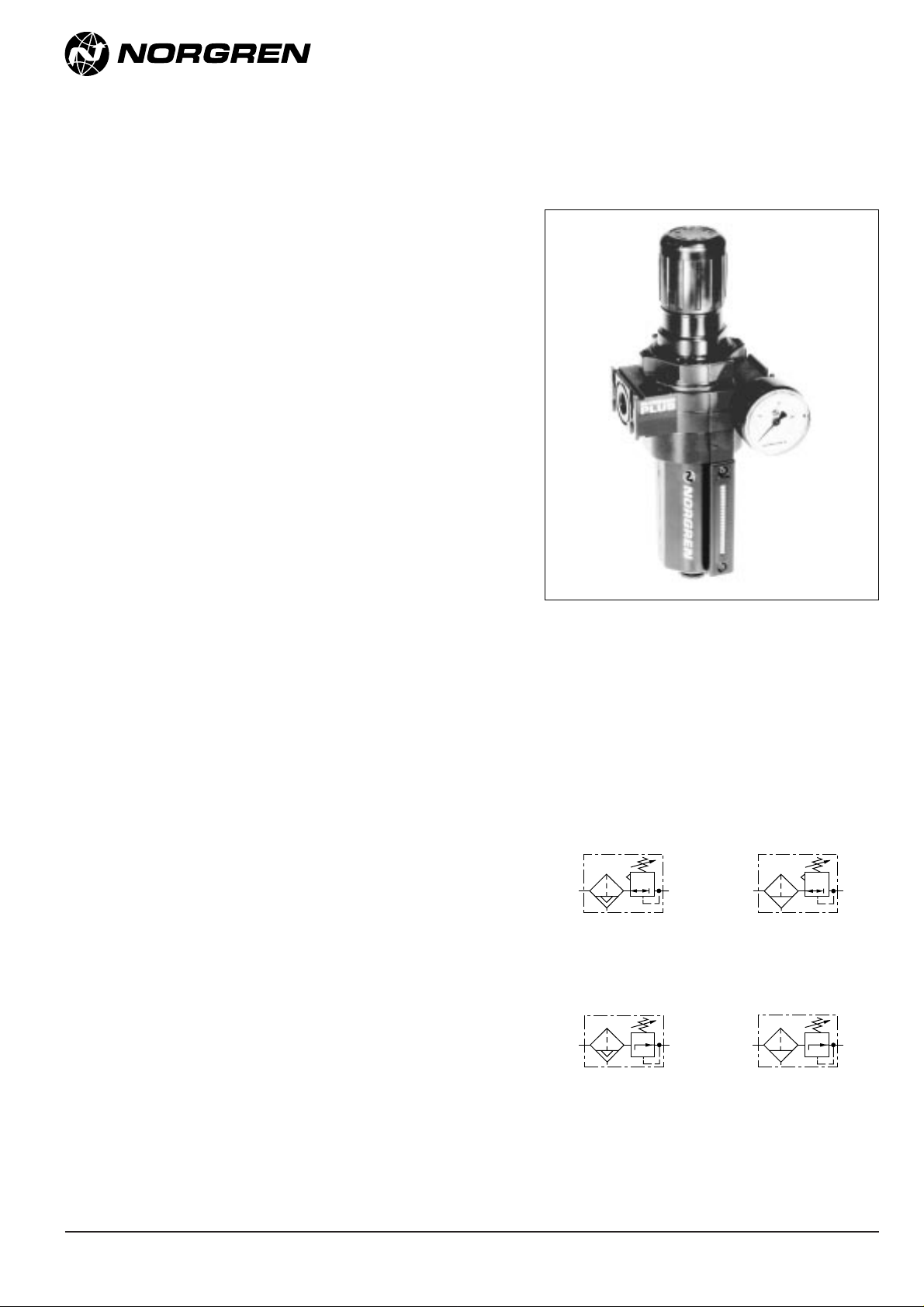
Olympian Plus
Filter/Regulator
1/4
"
, 3/8
",
1/2", 3/4"Port Sizes
● Olympian Plus plug in design
● High Efficiency water and particle removal
● Quick release bayonet bowl
● High visibility prismatic sight glass*
● Push to lock adjusting knob with tamper resistant
option
* UK and other patents pending
Technical Data
Fluid: Compressed air
Maximum pressure:
Guarded transparent bowl: 10 bar (150 psig)
Metal bowl: 17 bar (250 psig)
Operating temperature*:
Guarded transparent bowl: -20° to +50°C (0° to +125°F)
Metal bowl: -20° to +80°C (0° to +175°F)
* Air supply must be dry enough to avoid ice formation at temperatures below +2°C
(+35°F).
Partical removal: 5, 25 or 40 µm. Within ISO 8573-1, Class 3 and
Class 5
Typical flow at 6,3 bar (90 psig) inlet pressure:
106 dm3/s (225 scfm)
Automatic drain connection: 1/8
"
Automatic drain operating conditions:
Minimum pressure: 0,7 bar (10 psig).
Drain opens when bowl pressure drops below 0,2 bar (3 psig).
Minimum air flow: 1 dm3/s (2 scfm) required to close drain.
Gauge Ports:
1/8"PTF with PTF main ports
1/8"ISO Rc with ISO Rc main ports
1/8"ISO Rc with ISO G main ports
Nominal bowl size:
0,2 litre (7 fluid ounce)
Materials:
Body: Zinc
Bonnet: Aluminium
Valve: Brass
Yoke: Zinc
Metal bowl: Aluminium
Standard metal bowl prismatic liquid level indicator lens:
Grilamid
Optional metal bowl sight glass: Pyrex
Optional transparent bowl: Polycarbonate
Element: Sintered plastic
Elastomers: Synthetic rubber
Automatic Drain
Non Relieving
Manual Drain
Non Relieving
Back to Selector Page
Page 2
N/AL.8.240.300.02 7/97
Typical Performance Characteristics
B64G
Our policy is one of continuous research and development.
We reserve the right to amend, without notice, the specifications given in this document.
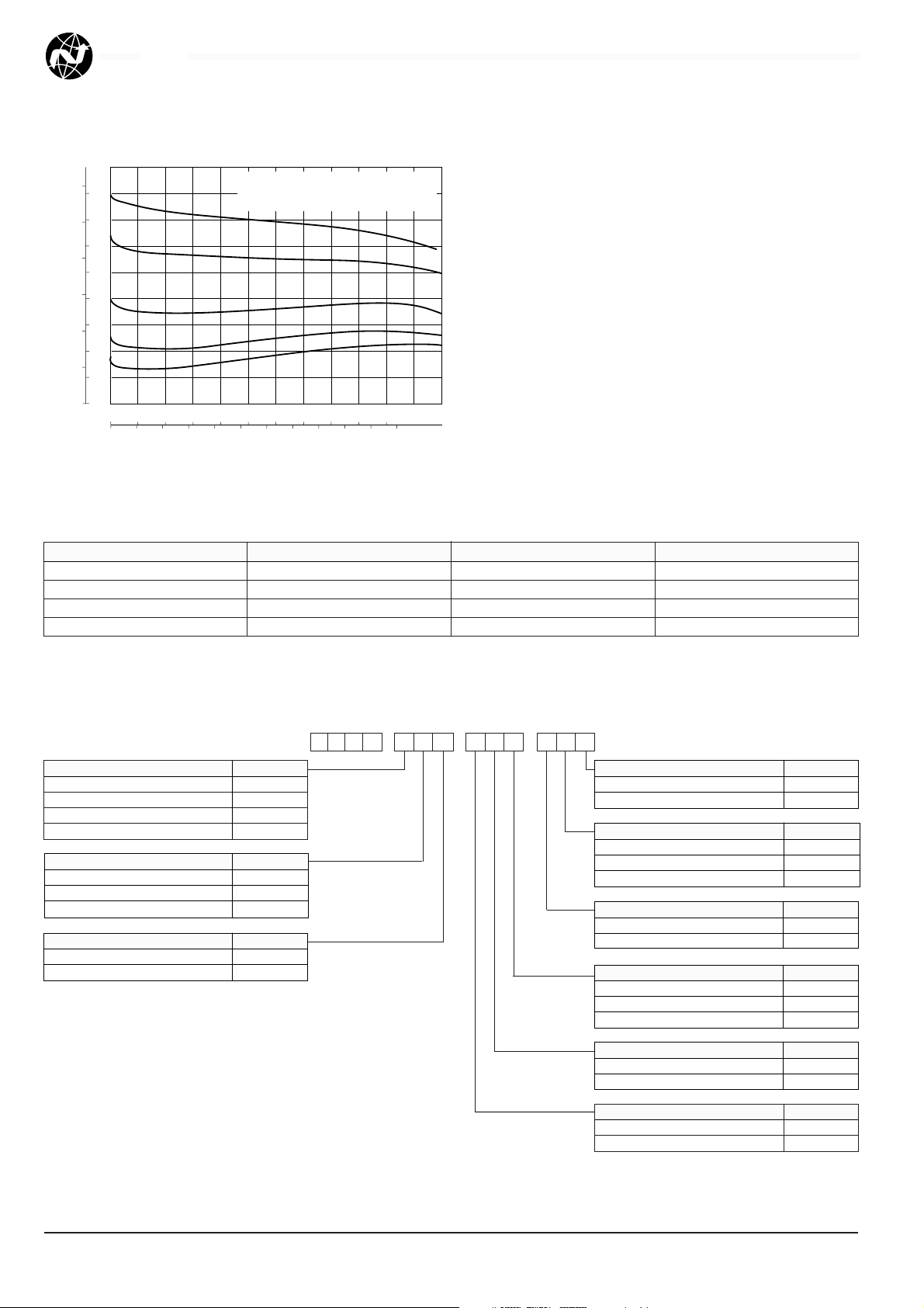
FLOW CHARACTERISTICS
0 20 40 60 80 100 dm3/s
AIR FLOW
0 40 80 120 160 200 240 scfm
8
6
4
2
0
OUTLET PRESSURE
bar g
100
80
60
40
20
0
psig
PORT SIZE: 1/2"40 µm ELEMENT
INLET PRESSURE: 10 bar (150 psig)
RANGE: 0,3 to 10 bar (5 to 150 psig)
Ordering Information. Models listed include ISO G threads, knob adjustment, automatic drain, metal bowl, 40 µm element, relieving
diaphragm and 0,3 to 10 bar (5 to 150 psig) outlet pressure adjustment range* without gauge.
† Typical flow with 10 bar (150 psig) inlet pressure, 6,3 bar (90 psig) set pressure and a 1 bar (15 psig) droop from set.
Port Size Model Flow†dm3/s (scfm) Weight kg (lb)
G1/4 B64G-2GK-AD3-RMN 30 (64) 1,71 (3.80)
G3/8 B64G-3GK-AD3-RMN 76 (161) 1,69 (3.76)
G1/2 B64G-4GK-AD3-RMN 106 (225) 1,66 (3.69)
G3/4 B64G-6GK-AD3-RMN N.A. 2,02 (4.49)
Alternative Models
B 6 4-G
★ ★
-
★★ ★ ★
Port Size Substitute
1/4
"
2
3/8
"
3
1/2
"
4
3/4
"
6
Threads Substitute
PTF A
ISO Rc taper B
ISO G parallel G
Diaphragm Substitute
Relieving R
Non relieving N
Element Substitute
5 µm 1
25 µm 2
40 µm 3
Adjustment Substitute
Knob K
T-bar T
Bowl Substitute
Metal with liquid level indicator D
Guarded Transparent P
-
★★ ★
Drain Substitute
1/4 turn manual M
Automatic A
Gauge Substitute
With G
Without N
Outlet Pressure Adjustment Range* Substitute
0,3 to 4 bar (5 to 60 psig) F
0,3 to 10 bar (5 to 150 psig) M
0,7 to 17 bar (10 to 250 psig) S**
* Outlet pressure can be adjusted to
pressures in excess of, and less than,
those specified. Do not use these units to
control pressures outside of the specified
ranges.
** Units with 17 bar (250 psig) adjustment
range are available only with the T-bar
adjustment; therefore substitute Tat the 7th
digit and
S
at the 12th position.
Page 3

* Reduces by 4 mm (0.16") with knob in locked
position. Add 37 mm (1.46") for unit with ‘T’ handle
† Minimum clearance required to remove bowl.
** 157 mm (6.18") for G3/4 models
7/97 N/AL.8.240.300.03
B64G
Our policy is one of continuous research and development.
We reserve the right to amend, without notice, the specifications given in this document.
105 (4.13)**
37 (1.46)
74 (2.91)
287 (11.3)*
303 (11.9)†
294 (11.6)*
310 (12.2)†
125 (2.92)*
125 (2.92)*
Accessories
Wall Mounting Bracket Tamper Resistant Kit Ø 50 mm
Pressure Gauge R1/8 Connection 1/8 PTF Connection
74504-50 4355-50 4 bar (60 psig): 18-013-012 18-013-202
Seal Wire: 2117-01 10 bar (150 psig): 18-013-013 18-013-204
25 bar (360 psig): 18-013-014 18-013-206
B64G (automatic drain) B64G (manual drain)
Dimensions mm (inches)
Panel mounting hole diameter: 52 mm (2.06")
Panel thickness: 0 to 6 mm (0"to 0.25")
Page 4

N/AL.8.240.300.04 7/97
B64G
Our policy is one of continuous research and development.
We reserve the right to amend, without notice, the specifications given in this document.
Warning
These products are intended for use in industrial compressed air
systems only. Do not use these products where pressures and
temperatures can exceed those listed under ‘Technical Data’.
Before using these products with fluids other than those specified, for
non-industrial applications, life-support systems, or other applications not
within published specifications, consult NORGREN.
Through misuse, age, or malfunction, components used in fluid
power systems can fail in various modes. The system designer is warned
to consider the failure modes of all component parts used in fluid power
systems and to provide adequate safeguards to prevent personal injury or
damage to equipment in the event of such failure.
System designers must provide a warning to end users in the
system instructional manual if protection against a failure mode
cannot be adequately provided.
System designers and end users are cautioned to review specific
warnings found in instruction sheets packed and shipped with these
products.
Water vapor will pass through these units and will condense into
liquid if air temperature drops in the downstream system. Install an air
dryer if water condensation could have a detrimental effect on the
application.
Service Kits
Item Type Part Number
Service kit
Relieving 4383-200
Non relieving 4383-201
5 µm 4338-01
Replacement elements 25 µm 4338-99
40 µm 4338-02
Replacement Sight Glass
Prismatic (standard) 4380-040
Pyrex 4380-041
Replacement Drains
Automatic 3000-97
Manual 684-84
Service kit includes diaphragm assembly, valve assembly,
valve spring, louvre o-ring, bowl o-ring, drain seal.
143 (5.63)
114 (4.49)
8,2 (0.32)
85 (3.35)
11 (0.43)
14,5 (0.57)
93 (3.66)
30,5 (1.20)
48 (1.89)
110 (4.33)
Bracket Mounting
Use 8 mm (5/16") screws to mount bracket to wall.
Bracket Kit Reference
Item Part Number
Wall Bracket 74504-50
 Loading...