

Page 1
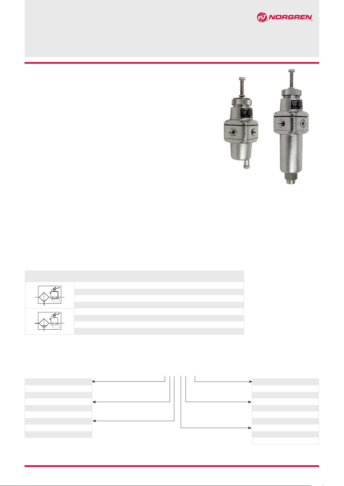
High flow filter/regulator designed for
use in corrosive environment
Metallic parts meet NACE* Standard MR-01-75
Applications include marine environment,
oil and gas productions
* National Association of Corrosion Engineers – recognised oil-field recommendation for
resistance to sulphide stress cracking common in well-head and other corrosive environments
Technical features
Medium:
Compressed air only
Maximum inlet pressure:
31 bar (manual drain)
17 bar (autodrain)
Outlet pressure range:
0,5 ... 10 bar
Flow:
40 dm3/s
Element:
5, 25 or40 μm
Port sizes:
1/4 NPT, 3/8 NPT, G1/4 or G3/8
1/4 PTF (gauge) and
1/4 NPT (automatic drain)
Drain:
Manual or automatic
Automatic drain operation
conditions (float operated):
B38P
High flow filter/regulator (stainless steel)
1/4 NPT, 3/8 NPT, G1/4 or G3/8
To close: > 0,3 bar,
To open: < 0,2 bar
Minimum air flow required to
close 1 dm
3
/s
Ambient/Media temperature:
-20 ... +80°C (FPM seals)
-40 ... +80°C (NBR seals)
Air supply must be dry enough
to avoid ice formation at
temperatures below +2°C.
Materials:
Body, bowl, bonnet, filter element
and adjusting screw:
316 stainless steel
Elastomers: FPM or NBR
Technical data, standard model, relieving and panel nut
Symbol Port size Outlet pressure *1)
*1) Outlet pressure can be adjusted to pressures in excess of, and less than,
those specified. Do not use these units to control pressures outside of the
specified ranges.
*2) Typical flow with 10 bar inlet pressure, 6,3 bar set pressure and a 1 bar drop
from set.
(bar)
1/4 NPT 0,5 ... 10 5 40 Manual 1,61 B38P-254-B1MA
3/8 NPT 0,5 ... 10 5 40 Manual 1,60 B38P-354-B1MA
1/4 NPT 0,5 ... 10 5 40 Automatic 1,74 B38P-254-A1MA
3/8 NPT 0,5 ... 10 5 40 Automatic 1,73 B38P-354-A1MA
Option selector
Port size * Substitute
1/4”
3/8”
Temperature range Substitute
-20 ... +80°C (FPM seals)
-40 ... +80°C (NBR seals)
Bracket Substitute
Inclusive
Without
* 1/2” port size on request
2
3
5
4
2
4
Element
(μm)
Flow *2)
3
/s)
(dm
B38P-˙˙˙-˙˙M˙
Drain Weight
(kg)
Model
Thread form Substitute
NPT
ISO G parallel
Element Substitute
5 µm
25 µm
40 µm
Drain Substitute
Automatic
Manual short bowl
A
G
1
2
3
A
B
7/14 2011-8168d
Our policy is one of continued research and development. We therefore reserve the right to amend,
without notice, the specifications given in this document. © 2014 Norgren China
N/en 8.530.350.01
Page 2
B38P
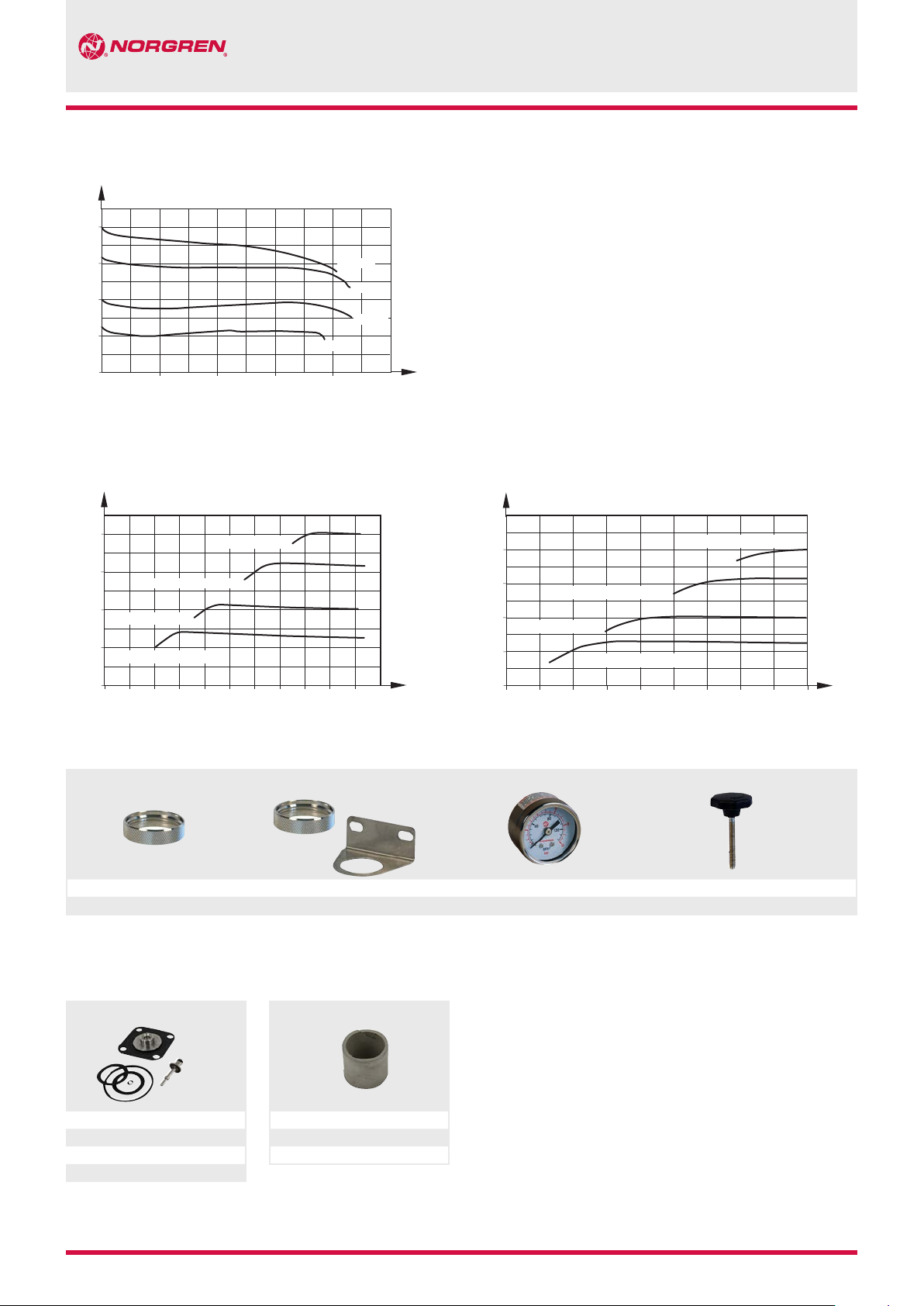
Flow characteristics
Inlet pressure: 10 bar, filter element: 5 μm, port size: 1/4 NPT
bar
8
6
4
2
Outlet pressureOutlet pressure (P2)
0
0
10 20 30 40
Flow
Regulating characteristics
bar
8
6
4
4 bar (0,37 dm /s)
2
2,5 bar (0,25 dm /s)
0
0
6,3 bar (0,56 dm /s)
Regulation 10 % flow Regulation 100 % flow
8 bar (0,7 dm /s)
3
3
3
21 43 65 87 10 11 bar9
8,0 bar
6,3 bar
4,0 bar
2,5 bar
3
dm
/s
bar
3
8
6
4
4 bar (3,7 dm /s)
Outlet pressure (P2)
2
0
0
6,3 bar (5,6 dm /s)
3
2,5 bar (2,5 dm /s)
21 43 76 9 108 bar
3
3
8 bar (7 dm /s)
3
Inlet pressure (P1)Inlet pressure (P1)
Accessories
Panel nut Neck mounting bracket Gauge *1) Plastic adjusting knob
5988-02 18-001-973 (includes panel nut) 18-013-913 (0 ... 6 bar, -40 ... 65°C) 74630-04
18-013-909 (0 ... 10 bar, -40 ... 65°C)
*1) Stainless steel items not strictly to NACE standard MR-01-75.
Spare parts Filter element
Reparatursatz
A080823-01 *2)
A080823-03 *3)
A080823-02 *4)
A080823-04 *5)
*2) manual drain, FPM
*3) manual drain, NBR
*4) auto drain, FPM
*5) auto drain, NBR
Filter element
5 µm: 5984-01
25 µm: A080874-02
40 µm: A080874-03
N/en 8.530.350.02
Our policy is one of continued research and development. We therefore reserve the right to amend,
without notice, the specifications given in this document. © 2014 Norgren China
2011-8168d 7/14
Page 3

Dimensions
B38P
Manual drain
0 ... 6
ø38
1
113 #
63
63
# Minimum clearance required to remove bowl
1
1/4 PTF Gauge port
2
1/8 PTF Exhaust port
117
55
48
13
200
Auto drain
2
ø38
1
172 #
1/4 NPT
63
63
0 ... 6
55
48
135 117
8,5
13
2
25
Neck mounting bracket
75
54
8,5
1,5
35
65
41
25
6,5
38
Warning
These products are intended for use in industrial compressed air
systems only. Do not use these products where pressures and
temperatures can exceed those listed under »Technical features«.
Before using these products with fluids other than those specified,
for non-industrial applications, life-support systems, or other applications not within published specifications, consult NORGREN.
Through misuse, age, or malfunction, components used in
fluid power systems can fail in various modes.
The system designer is warned to consider the failure modes
of all component parts used in pneumatic systems and to provide
adequate safeguards to prevent personal injury or damage to
equipment in the event of such failure.
System designers must provide a warning to end users in
the system instructional manual if protection against
a failure mode cannot be adequately provided.
System designers and end users are cautioned to review specific
warnings found in instruction sheets packed and shipped with
these products.
7/14 2011-8168d N/en 8.530.350.03
Our policy is one of continued research and development. We therefore reserve the right to amend,
without notice, the specifications given in this document. © 2014 Norgren China
 Loading...