

Page 1
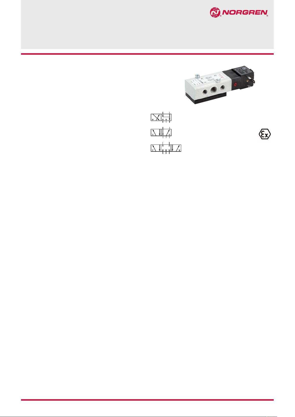
electromagnetic actuated, indirectly controlled
For single and double operated actuators
Crossover-free switching, switch-over
function guaranteed even with small cross
section air supply
Valve switches at power failure into starting
position (mechanical return spring,
monostable design)
Manual override with detent standard
The solenoid valves are applicable in the
protection class
- Ex m for zones 1, 2, 21, 22 (gases and dusts)
ATEX cat.II 2GD
- Ex ia for zones 1, 21, (gases) ATEX cat.II 2G,
- Ex nA, for zones 2, 22 (gases and dusts)
ATEX cat.II 3 GD
97100 NAMUR
3/2, 5/2 & 5/3 way spool valves
flanged with NAMUR Interface, G 1/4, 1/4 NPT
Approval depends on magnetic
system, see pages 2, 3 and 4!
Technical features
Medium:
Filtered, non-lubricated
or dry compressed air
Operation:
Indirectly solenoid operated
soft seal valves
Operating pressure:
2 ... 8 bar
Orifice:
6 mm
Port size:
1: G 1/4, 1/4 NPT
3 and 5: G 1/8, 1/8-NPT
NAMUR Interface with integrated
exhaust air
Flow direction:
Fixed
Mounting position:
Optional
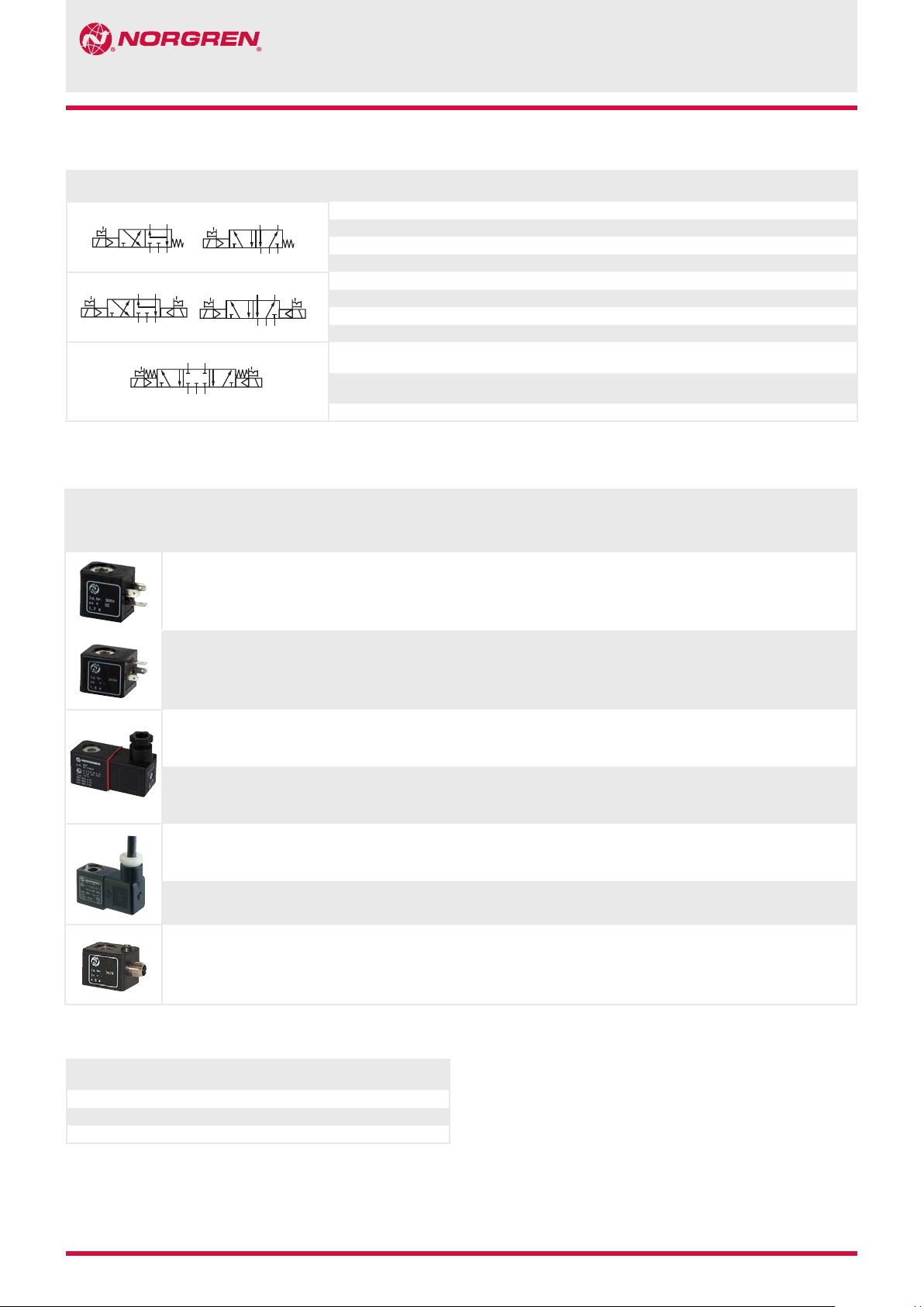
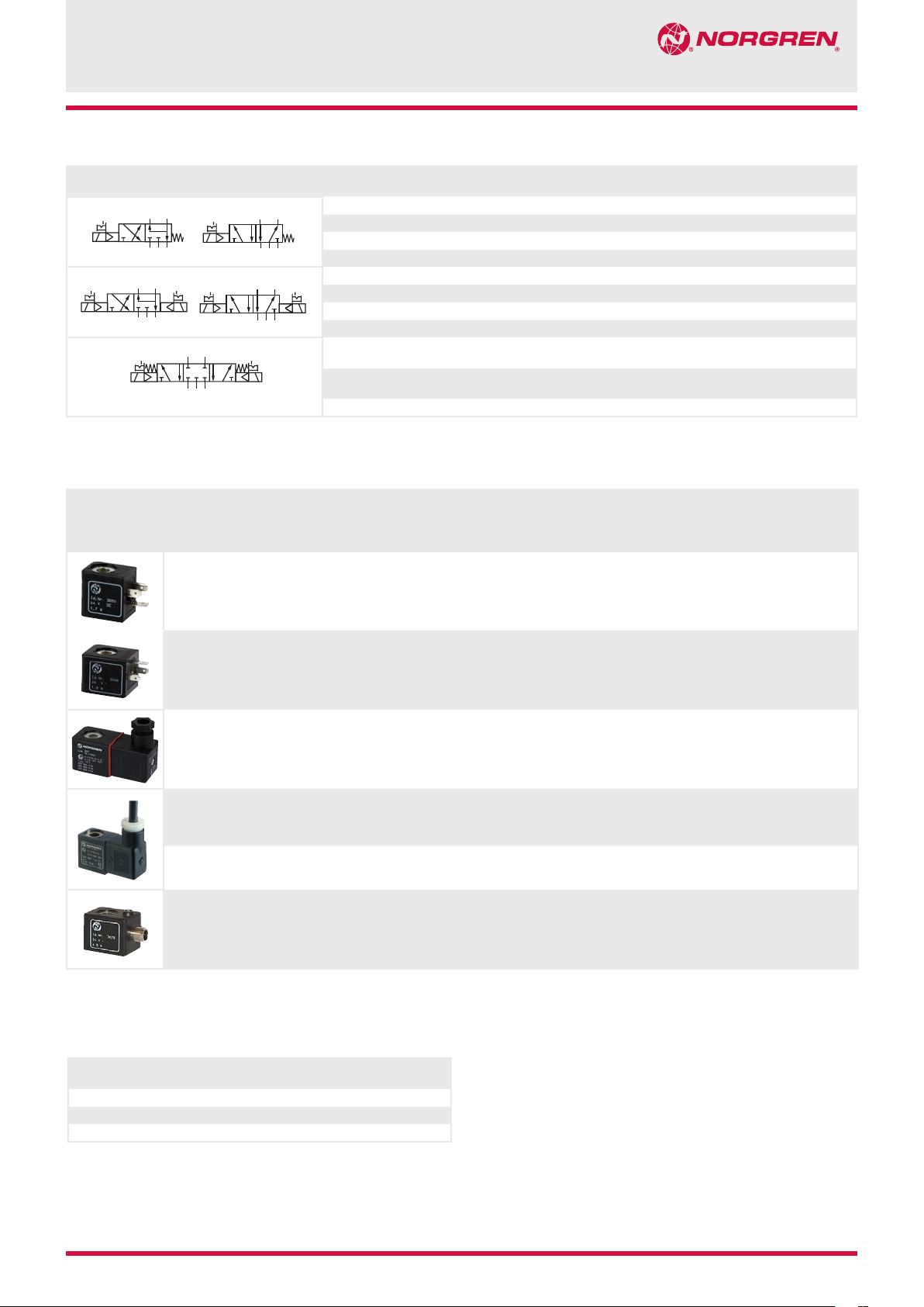
Electrical connection:
See solenoid table
Fluid/Ambient temperature:
-15 ... +60°C,
Depending on solenoid system
Air supply must be dry enough
to avoid ice formation at
temperatures below +2°C.
Materials:
Housing: Aluminium 3.0615
anodized
Pilot flange: Plastic (PBT)
Seals: NBR (Perbunan)
9/13 2004-5152c
Our policy is one of continued research and development. We therefore reserve the right to amend,
without notice, the specifications given in this document. © 2013 Norgren GmbH
N/en 5.4.372.01
Page 2
97100 NAMUR
42
315
5
15
3
52 EMH
H
315
15
3
42
513
MR
Technical data
Standard version, 5/2 or 3/2 indirect acting valves (conversion instructions see page 6)
Symbol Por size
24
42
*1) When ordering please indicate solenoid, voltage and current type (frequency).
Valve function: APB = All Ports Blocked
24
1 3, 5 2, 4
G 1/4 G 1/8 Flange Solenoid/spring 2 ... 8 750 0,25 1 9710000
1/4 NPT 1/8 NPT Flange Solenoid/spring 2 ... 8 750 0,25 1 9710010
G 1/4 G 1/8 Flange Solenoid/solenoid 2 ... 8 750 0,35 2 9711000
1/4 NPT 1/8 NPT Flange Solenoid/solenoid 2 ... 8 750 0,35 2 9711010
G 1/4 G 1/8 Flange Solenoid/solenoid
1/4 NPT 1/8 NPT Flange Solenoid/solenoid
Solenoid operators for standard version 971xxx0 only
Power consumption
24 V d.c. 230 V a.c.
(W) (VA)
1,8 — 70 — — IP 65 (with connector) -15 ... +50 Connector
Rated current
24 V d.c. 230 V a.c.
(m A) (m A)
Ex-Protection IP-Protection class
(to EN 60529)
Ex-Protection
(ATEX-Category)
Actuation Operating
mid position APB
mid position APB
Temperature
Ambient/Fluid
(°C)
pressure (bar)
2 ... 8 500 0,40 3 9712000
2 ... 8 500 0,40 3 9712010
Electrical
connection
DIN EN 175301-803
Form B *6)
Flow
(l/min)
Weight
(kg)
Weight
(kg)
0,1 11 1 3050
Dimension
No.
Dimension
Nr.
Circuit
diagram
Nr.
Model *1)
Model
1,6 3,5 30 — — IP 65 (with connector) -15 ... +50 Steckverbinder
2 — 85 — II3G
II3D
— 2,0 — 18 II3G
II3D
— 5,0 — 22 II2G
II2D
2,7 — 115 — II2G
II2D
2,7 — 115 — — IP 66 (with connector) -10 ... +50 Connector M12x1,
Standard voltages (±10%) 24 V d.c., 230 V a.c. Further versions on request.
*6) Connector is not scope of delivery, see table »Accessories«
Ex nA IIC T5 Gc
Ex tc IIIC T95° Dc
IP 65 (with connector)
Ex nA IIC T5 Gc
Ex tc IIIC T95° Dc
IP 65 (with connector)
Ex mb IIC T4/T5 Gb
Ex mb IIC T4 Gb
Ex mb tb T130°C Db
IP65 (with connector)
Ex mb IIC T5 Gb
Ex mb tb T95°C Db
IP65 (with connector)
Approvals
Model Approvals
ATEX IECEx FM
304x PTB 06 ATEX 2055 — — N/de 7.1.555
306x PTB 03 ATEX 2015 — — N/en 7.1.560
307x EC-Declaration of Conformity — — N/en 7.1.565
Datasheet
DIN EN 175301-803
Form A *6)
-15 ... +50 With special
connector
DIN EN 175301-803
Form A
-15 ... +50 With special
connector
DIN EN 175301-803
Form A
-20 ... +50 3 m cable 0,3 13 15 3061
-20 ... +50 3 m cable 0,3 13 14 3062
DIN IEC 61076-2-101
*6)
Solenoid with yellow
LED
0,1 12 1 3036
0,3 12 1 3046
0,3 12 1 3047
0,1 14 17 3071
N/en 5.4.372.02
Our policy is one of continued research and development. We therefore reserve the right to amend,
without notice, the specifications given in this document. © 2013 Norgren GmbH
2004-5152c 9/13
Page 3
Valves for minimal electrical power, incl. Ex i,
35
42
315
15
3
15
3
52 EM
H
315
15
3
24
513
R
5/2 or 3/2 indirect acting valves (conversation intsructions see page 6)
Symbol Port size
24
1 3, 5 2, 4
G 1/4 G 1/8 Flange Solenoid/spring 2 ... 8 750 0,25 1 9710002
1/4 NPT 1/8 NPT Flange Solenoid/spring 2 ... 8 750 0,25 1 9710012
Actuation Operating
pressure (bar)
Flow
(l/min)
97100 NAMUR
Weight
(kg)
Dimension
No.
Model *1)
42
42
*1) When ordering please indicate solenoid, voltage and current type (frequency).
Valve function: APB = All Ports Blocked
G 1/4 G 1/8 Flange Solenoid/solenoid 2 ... 8 750 0,35 2 9711002
1/4 NPT 1/8 NPT Flange Solenoid/solenoid 2 ... 8 750 0,35 2 9711012
G 1/4 G 1/8 Flange Solenoid/solenoid
1/4 NPT 1/8 NPT Flange Solenoid/solenoid
Solenoid actuators
Power consumption
24 V d.c. 230 V a.c.
(W) (VA)
1,8 — 70 — — IP 65 (with connector) -15 ... +50 Connector
0,7 2,0 *2) 29 4 — IP 65 (with connector) -15 ... +50 Connector
2 — 85 — II3G
Rated current
24 V d.c. 230 V a.c.
(m A) (m A)
Ex-Protection IP-Protection class
II3D
(to EN 60529)
Ex-Protection
(ATEX-Category)
Ex nA IIC T5 Gc
Ex tc IIIC T95° Dc
IP65 (with connector
mid position APB
2 ... 8 500 0,40 3 9712002
2 ... 8 500 0,40 3 9712012
mid position APB
Temperature
Ambient/Fluid
(°C)
-15 ... +50 With special
Electrical
connection
DIN EN 175301-803
Form B *6)
DIN EN 175301-803
Form A *6)
connector
DIN EN 175301-803
Form A
Weight
Dimension
(kg)
Nr.
0,1 11 1 3050
0,1 12 1 3034
0,3 12 1 3046
Circuit
diagram
Nr.
Model
— 5,0 — 22 II2G
II2D
2,7 — 115 — II2G
II2D
2,7 — 115 — — IP 66 (with connector) -10 ... +50 Connector M12x1,
Standard voltages (±10%) 24 V d.c., 230 V a.c. Further versions on request.
*2) Valves can be operated with DC only. For 230V AC application please use 206V DC coil together with recifier plug: model 0663303
*6) Connector is not scope of delivery, see table »Accessories«
Ex mb IIC T4/T5 Gb
Ex mb IIC T4 Gb
Ex mb tb T130°C Db
IP65 (with connector)
Ex mb IIC T5 Gb
Ex mb tb T95°C Db
IP65 (with connector)
-20 ... +50 3 m cable 0,3 13 15 3061
-20 ... +50 3 m cable 0,3 13 14 3062
DIN IEC 61076-2-101
*6)
Solenoid with yellow
LED
0,1 14 17 3071
Approvals
Model Approvals
304x PTB 06 ATEX 2055 — — N/de 7.1.555
306x PTB 03 ATEX 2015 — — N/en 7.1.560
307x EC-Declaration of Conformity — — N/en 7.1.565
ATEX IECEx FM
Datasheet
9/13 2004-5152c N/en 5.4.372.03
Our policy is one of continued research and development. We therefore reserve the right to amend,
without notice, the specifications given in this document. © 2013 Norgren GmbH
Page 4

97100 NAMUR
For intrinsically safe circuits,
Protection class Ex ia IIC T6/T4 Ga (cat. II 2G)
Nominal resistance
N coil
R
Ω
)
(
275 37 345 13,8 T6 -40 ... +50
When selecting an intrinsically safe power supply, the permissible maximum values according to the Certificate of Conformity should be taken in account.
On the other hand, the low effective inductivity and capacity can be ignored.
*6) Connector not supplied, required connector: model 0570275
Required switching
current min.
(mA)
Approvals
Model Approvals
3039 PTB 03 ATEX 2134 — CSA-LR 51090-4 N/en 7.1.550
ATEX IECEx FM
Resistance
R
W 50 coil
Ω
)
(
Required voltage
at terminal
RW 50 (V)
Datasheet
Temperature
Ambient/
Fluid(°C)
T4 -40 ... +85
Electrical
connection
Connector
DIN EN 175301-803
Form A *6)
IP65 (with connector)
Weight
(kg)
0,2 15 13 3039
Dimension
No.
Circuit
diagram
No.
Model
N/en 5.4.372.04
Our policy is one of continued research and development. We therefore reserve the right to amend,
without notice, the specifications given in this document. © 2013 Norgren GmbH
2004-5152c 9/13
Page 5

Options selector 971˙0˙˙.˙˙˙˙.˙˙˙.˙0
97100 NAMUR
Function Substitute
5/2 way valve, spring return
(3/2 way valve by swapping
enclosed adaptor plate)
5/2 way impuls valve
(3/2 way valve by swapping
enclosed adaptor plate)
5/3 way valve, APB
(all ports blocked)
0
1
2
Voltage Substitute
24 V d.c.
230 V a.c.
Solenoids Substitute
see table
Manual override Substitute
Push and lock
Push and lock, Ex i version only
Port size Substitute
G 1/4
1/4 NPT
0
1
Accessories
Connector
DIN EN 175301-803
0570275 Form A 0523055 (without cable) 0523056 (90°, without cable) C/S1 (1/8 NPT) 0612790 (NAMUR single connection plate) 0540593
0663303 Form A (with rectifier) 0523057 (2 m cable) 0523058 (90°, 2 m cable length) M/S1 (G 1/8) 0612791 (NAMUR-rip use in combination with 0612790, Alu)
0680003 Form B 0523052 (5 m cable) 0523053 (90°, 5 m cable length)
Connector
M12 x 1
M12 x 1
Silencer
Page 8
Flange plate
Page 8
Yok e
Page 8
024.0
230.5
0
2
Dimensions
Valves
1
1
G 1/4
1 3
5
G 1/8
1
O ring ø 6 x 2 mm in scope with delivery
2
Hole (3 mm deep) coding stud
32
40
12
2
24
4
2
24,5
131,5
56,5
38,5
20,5
1
0
25
37,2
7,2
2 3
3
M5
5,5
13
19,5
G 1/4
G 1/8
315
1
12
24
206
2
4 2
98
112
1
3
0
M5
5.5
18 18
0
1
13
19.5
32
40
9/13 2004-5152c N/en 5.4.372.05
Our policy is one of continued research and development. We therefore reserve the right to amend,
without notice, the specifications given in this document. © 2013 Norgren GmbH
25
37.2
7.2
Page 6

97100 NAMUR
38,5
10
29,522
72
29,5
30
29,5
30
Dimensions
Solenoid operators
13
29,5
22
29
11
65
Ø
9
1
12
1211
36
M16 X 1,5
15
69
Ø
9
1
15
41,5
12
28
14
29
M12x1
~58
4
3
1
2
29,5
14,5
15
18
1
Connector 4 x 90° turnable
39
M16 X 1,5
29,5
Ø
9
1
Electrical connection M 12 x 1
23
5
14
Pin Signal Cable
15,5
41,5
1 + UB brown
2 Out 2 (PNP) / analogue 4 to 20 mA white
3 0 Volt blue
4 Out 1 (PNP) black
12
28
Ø9
N/en 5.4.372.06
Our policy is one of continued research and development. We therefore reserve the right to amend,
without notice, the specifications given in this document. © 2013 Norgren GmbH
2004-5152c 9/13
Page 7

Circuit diagrams
32
1
97100 NAMUR
1
13
17
2
3
4
NAMUR hole pattern (driving side)
M5
4
2
2
Port 2 (A)
3
Coding stud threaded
4
M5 & M6 (10 deep)
5
Port 3 (R)
14
15
2
3
3
24
NAMUR quick exhaust module for a better
kv-value by exhaust see data sheet 5.4.820
NAMUR interlinking plates in redundancy design
for »safety exhausting« and »safety ventilating«
5
see data sheet 5.4.830
Conversion instructions of 5/2 into
3/2 way function
5/2 way function (original mode of supply)
5/2
67
3/2 resp. 5/2 way function according to version
by swapping or turning enclosed adaptor plates.
Make sure Marker and Arrow do match as shown
on above drawing. Original mode of supply:
5/2 function.
3/2 way function
3/2
67
6
Arrow
7
Marker
9/13 2004-5152c N/en 5.4.372.07
Our policy is one of continued research and development. We therefore reserve the right to amend,
without notice, the specifications given in this document. © 2013 Norgren GmbH
Page 8

97100 NAMUR
19
25,5 M 5 (4x)
60
51
12
50
ø 12,5
34
Single connection plate
Model: 0612790
19
G 1/4
30 19
Yoke
Model: 0540593
NAMUR slot
Model: 0612791
25,5
41
12 12
34,5
104
ø 9,5
ø 5,5
29
12
10
ø 14,5
19
G 1/4
2127ø 9
11,5
19
35
1616
9,5
5,5
41
5,5
5
11
60°
2x
65
M 5
41
205
12
Silencer
Model: M/S1, C/S1
6,5
1/8”
Warning
These products are intended for use in industrial compressed air
systems only. Do not use these products where pressures and
temperatures can exceed those listed under ‘Technical features’.
Before using these products with fluids other than those specified,
for non-industrial applications, life-support systems, or other
applications not within published specifications, consult NORGREN.
Through misuse, age, or malfunction, components used in fluid
power systems can fail in various modes.
N/en 5.4.372.08
Our policy is one of continued research and development. We therefore reserve the right to amend,
without notice, the specifications given in this document. © 2013 Norgren GmbH
The system designer is warned to consider the failure modes of all
component parts used in fluid power systems and to provide adequate
safeguards to prevent personal injury or damage to equipment in the
event of such failure.
System designers must provide a warning to end users in the system
instructional manual if protection against a failure mode cannot be
adequately provided.
System designers and end users are cautioned to review specific
warnings found in instruction sheets packed and shipped with these products.
2004-5152c 9/13
 Loading...