

Page 1
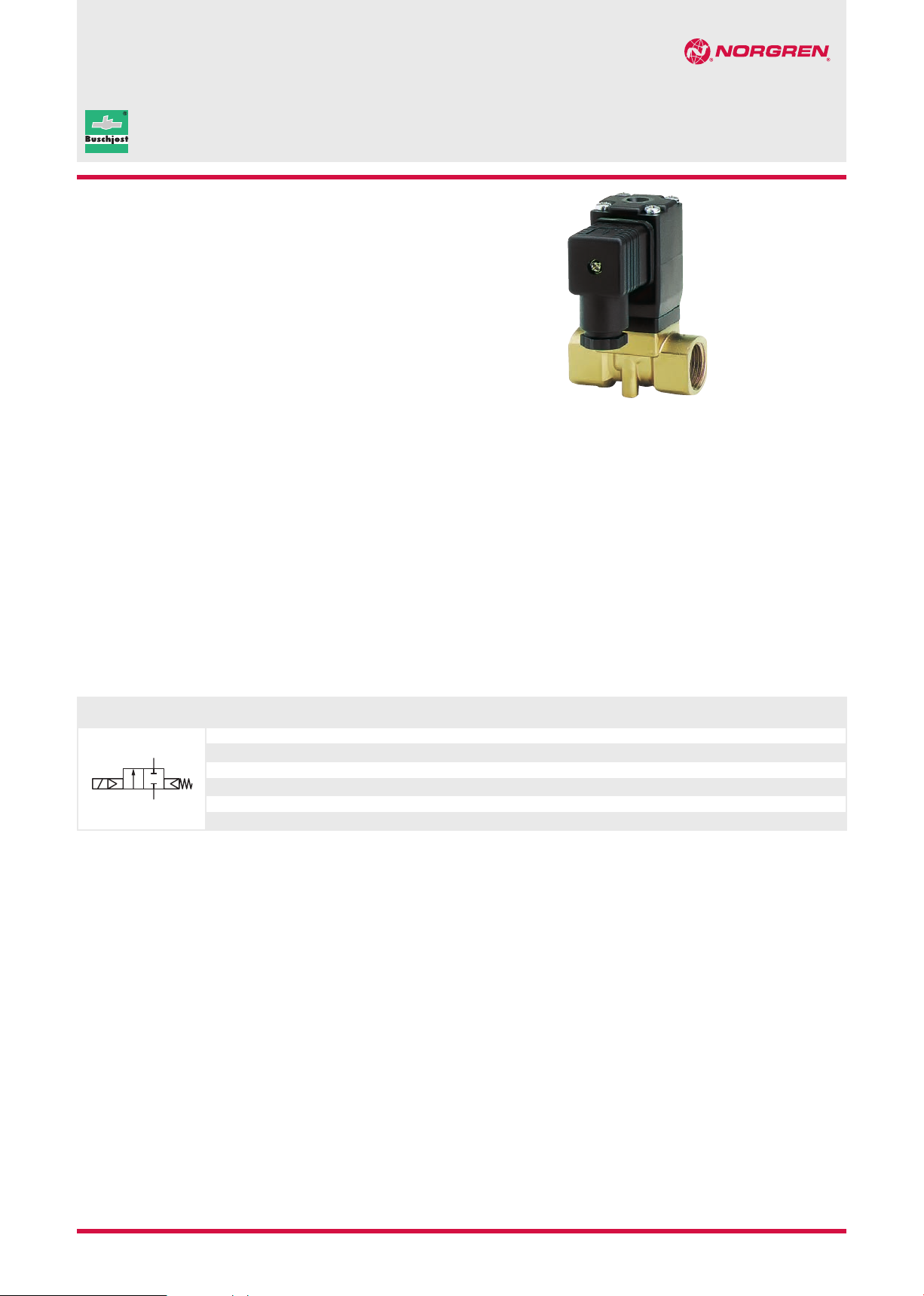
Suitable for vacuum
Functional design
Compact solenoid with integrated core tube
Valve operates without differential pressure
Operating pressure 0 … 20 bar
with alternating current and NBR sealing
Technical features
Medium:
Neutral gases and liquids
Switching function:
Normally closed
Operation:
Solenoid actuated,
with forced lifting
Mounting position:
Optional,
preferably solenoid
vertical on top
Flow direction:
Determined
Port size:
G1/4, G3/8, G1/2,
1/4 NPT, 3/8 NPT, 1/2 NPT
Operating pressure:
0 … 10 bar
DN 10, G1/4 ... 1/2, 1/4 ... 1/2 NPT
Fluid temperature:
–10 ... +90°C
Ambient temperature:
–10 ... +50°C
82530/82630
2/2-way diaphragm valves
Material:
Body: Brass (CW617N), PA66
Seat seal: NBR
Internal parts: Stainless steel,
PVDF
For contaminated fluids insertion
of a strainer is recommended.
Technical data - standard models
Symbol Port size Orifice
G1/4 10 44 1,5 0 ... 10 0,5 8253000.8001.xxxxx
A
P
xxxxx Please insert voltage and frequency codes
*1) Cv-value (US) ≈ kv value x 1,2
*2) For gases and liquid fluids up to 25 mm
1/4 NPT 10 44 1,5 0 ... 10 0,5 8263000.8001.xxxxx
G3/8 10 44 1,7 0 ... 10 0,5 8253100.8001.xxxxx
3/8 NPT 10 44 1,7 0 ... 10 0,5 8263100.8001.xxxxx
G1/2 10 60 1,7 0 ... 10 0,6 8253200.8001.xxxxx
1/2 NPT 10 60 1,7 0 ... 10 0,6 8263200.8001.xxxxx
2
/s (cSt)
(mm)
Valve length
(mm)
Flow kv value *1)
3
/h)
(m
Operating pressure
*2) (bar)
Weight
(kg)
Model
Solenoid in V d.c./a.c.
Our policy is one of continued research and development. We therefore reserve the right to amend,
without notice, the specifications given in this document. © 2014 Buschjost GmbH
N/en 5.8.102.0107/14 2014-5732d
Page 2
82530/82630
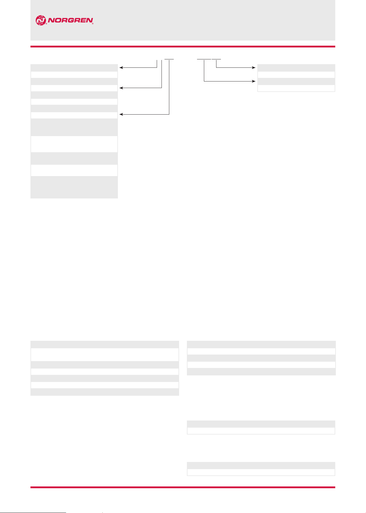
Option selector
Thread form Substitute
ISO G
NPT
Port size Substitute
1/4
3/8
1/2
Valve options Substitute
Seat seal FPM,
for fuel and oil,
max. fluid temperature +110°C
Seat seal EPDM,
for hot water,
max. fluid temperature +110°C
Degreased version,
Seat seal FPM
Operating pressure 0 ... 20 bar,
only for NBR and a.c. solenoid
Seat seal HNBR,
for hot water and steam,
Operating pressure 0 ... 6 bar,
Fluid temperature 0 ... +150°C
82˙3˙˙˙.8001.˙˙˙˙˙
Frequency Substitute
5
6
0
1
2
03
14
18
22
51
See table frequency codes
Voltage Substitute
See Voltage codes
xx
xxx
Standard solenoid systems
Voltage and Frequency Solenoid 8001
Code
Voltage
024 00 24 V d.c. - 12 W 12 W
024 50 24 V a.c. 50 Hz 20 VA 20 VA
110 50 110 V a.c. 50 Hz 20 VA 20 VA
120 60 120 V a.c. 60 Hz 20 VA 20 VA
230 50 230 V a.c. 50 Hz 20 VA 20 VA
Further versions on request!
Code
Frequency
2014-5732d
Voltage Frequency Power consumption
Inrush Holding
Our policy is one of continued research and development. We therefore reserve the right to amend,
without notice, the specifications given in this document. © 2014 Buschjost GmbH
Electrical details for all solenoid systems
Design DIN VDE 0580
Voltage range ±10%
Duty cycle 100% ED
Protection class EN 60529 IP65
Socket Form A acc. to DIN EN 175301-803 (included)
According to DIN VDE 0580 at a solenoid temperature of +20°C.
At operating state temperature the input power of a coil decreases by up to
ca. 30% due to physical reasons.
x
Additional solenoid systems
ATEX category Protection class Solenoid Standard voltages
II2GD EEx me II T3 T 140°C 8041 24 V d.c., 110 V a.c., 230 V a.c.
Attention!
The conditions imposed on the Ex approvals lead to reduction of the permissible
standard temperature ranges in the cases of explosion protected solenoids.
Additional solenoid systems
Option Solenoid Standard voltages
D.c. solenoid with rectifier for a.c. only 8004 24 V d.c., 110 V a.c., 230 V a.c.
N/en 5.8.102.0207/14
Page 3

Section View
G1/4 ... 1/2
1/4 ... 1/2 NPT
1501
1400
400
705
702
1502
103
102
101
82530/82630
PA
No. Description
101 Valbe body
*102 Diaphragm
103 Spacer
400 Solenoid
*702 Plunger
*705 Pressure spring
1400 Socket (included)
1501 Oval head cap screw
*1502 O-ring
* These individual parts form a complete wearing unit.
When ordering spare parts please state Model No. and Series No.
Our policy is one of continued research and development. We therefore reserve the right to amend,
without notice, the specifications given in this document. © 2014 Buschjost GmbH
N/en 5.8.102.0307/14 2014-5732d
Page 4

82530/82630
Note to Pr
The va
Equipment Dir
pr
member c
T
c
Dimensions
G1/4 ... 1/2
1/4 ... 1/2 NPT
17,5
69,5
35
34
1816
20,5
H1
H
P A
B
L
Port size R B H H1 L T Model
G1/4 14 87 73 44 21 12 8253000.8001.xxxxx
1/4 NPT 14 87 73 44 21 10 8263000.8001.xxxxx
G3/8 14 87 73 44 21 12 8253100.8001.xxxxx
3/8 NPT 14 87 73 44 21 10 8263100.8001.xxxxx
G1/2 14 90 74,5 60 27 15 8253200.8001.xxxxx
1/2 NPT 14 90 74,5 60 27 13 8263200.8001.xxxxx
1
2
R
T
ca. 40
1
Solenoid rotatable 360°
2
Socket turnable 4 x 90°
(Socket included)
essure Equipment Directive (PED):
lves of this series are according to Art. 3 § 3 of the Pressure
ective (PED) 97/23/EG. This means interpretation and
oduction are in accordance to engineers practice wellknown in the
ountries.
he CE-sign at the valve refers not to the PED. Thus the declaration of
onformity is not longer applicable for this directive.
Our policy is one of continued research and development. We therefore reserve the right to amend,
without notice, the specifications given in this document. © 2014 Buschjost GmbH
Note to Electromagnetic Compatibility Guideline (EEC):
The valves shall be provided with an electrical circuit which ensures the
limits of the harmonised standards EN 61000-6-3 and EN 61000-6-1 are
observed, and hence the requirements of the Electromagnetic
Compatibility Guideline (2004/108/EG) satisfield.
N/en 5.8.102.0407/14 2014-5732d
 Loading...