

Nordyne Q4SE, Q4SE-X60, Q4SE-X48, Q4SE-X36, Q4SE-X24 Installation Manual
Q4SE SERIES 14 SEER
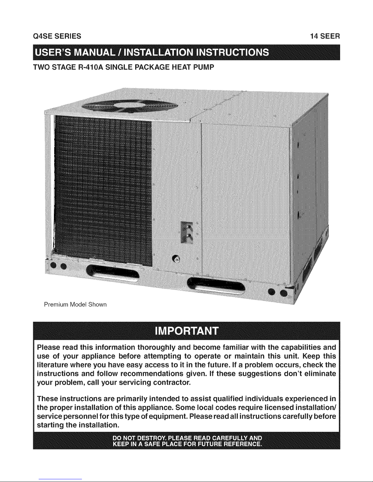
TWO STAGE R-410A SINGLE PACKAGE HEAT PUMP
Premium Model Shown
Please read this information thoroughly and become familiar with the capabilities and
use of your appliance before attempting to operate or maintain this unit. Keep this
literature where you have easy access to it in the future. If a problem occurs, check the
instructions and follow recommendations given. If these suggestions don't eliminate
your problem, call your servicing contractor.
These instructions are primarily intended to assist qualified individuals experienced in
the proper installation of this appliance. Some local codes require licensed installation/
service personnel for this type of equipment. Please read all instructions carefully before
starting the installation.
important Safety information .................................... 3
About the Heat Pump ................................................. 3
Operating instructions ............................................... 3
Cooling Operation ..................................................... 3
Heating Operation ..................................................... 3
Emergency Heat ........................................................ 3
Defrost Operation ...................................................... 3
Operating the Heat Pump for Automatic
Cooling and Heating .................................................. 4
Oper. the Indoor Blower Continuously ....................... 4
Shutting the Heat Pump Off ...................................... 4
System Maintenance .................................................. 4
Regular Cleaning ....................................................... 4
Before You Call a Technician ..................................... 4
Troubleshooting .......................................................... 4
Warranty information ................................................. 4
Important Safety Information .................................... 5
General Information ................................................... 6
Pre -Installation Check ............................................. 6
Locating the Heat Pump Unit .................................... 6
Field Connections for Electrical Power
Supply ....................................................................... 6
Air Ducts ................................................................... 6
Unconditioned Spaces ........................................... 6
Acoustical Duct Work ............................................. 6
Air Filter Requirements ............................................. 7
Condensate Drain .................................................... 7
Heat Pump installation ............................................... 7
Packaging Removal ................................................... 7
Rigging and Hoisting ................................................. 7
Minimum Clearance Requirements ........................... 7
Horizontal to Downflow Conversion ........................... 7
Ground Level ............................................................. 8
Rooftop ...................................................................... 8
Electrical Wiring .......................................................... 8
Pre - Electrical Checklist ........................................... 8
Wiring Diagram / Schematic ...................................... 8
Line Voltage ............................................................... 8
Grounding .................................................................. 9
Selecting Proper Airflow for Variable Speed Units .....9
Selecting Basic Cool/Heat Pump Airflow ............... 9
Selecting Minimum Electric Heat Airflow ................ 9
Selecting the Delay Profile ..................................... 9
Demand Defrost Control .......................................... 11
Optional Comfort Alert TM Diagnostics Module ......... 11
24VAC Power Wiring ............................................ 11
Thermostat Demand Wiring ................................. 11
L Terminal Wiring ................................................. 11
DC SOL Connection ............................................ 12
Interpreting the Diagnostic LED's ......................... 12
LED Description ................................................... 12
Installation Verification ......................................... 12
Troubleshooting the Installation ............................ 12
Optional Humidistat ................................................. 13
Optional Electric Heater Kits ................................... 13
Optional Outdoor Thermostat .................................. 13
Ambient Sensor Mounting ....................................... 13
Thermostat Connections ......................................... 14
Startup & Adjustments ............................................ 14
Pre - Start Checklist ................................................ 14
Start-up Procedure .................................................. 14
Air Circulation ....................................................... 14
Short Cycle Protection ......................................... 14
System Cooling .................................................... 14
System Heating .................................................... 15
Refrigerant Chargmg ............................................... 15
Charging an R-410A Unit in AC Mode .................... 15
Charging an R-410A Unit in Heating Mode ............. 15
Heat Pump Maintenance .......................................... 15
Figures & Tables ....................................................... 16
Figure 9. Q4SE Heat Pump Dimensions .............. 16
Table 7. Center of Gravity & Shipping Weights ..... 16
Electrical Information ............................................... 17
Figure 10. Heat Pump T-Stat Connections ........... 17
Figure 11. Wiring Diagram for Two-Stage Cool &
Two-Stage Heat ................................... 18
Figure 12. Wiring Diagram for Two-Stage Cool &
Two-Stage Heat w/Comfort Alert ........ 19
Cooling Charging Charts ......................................... 20
Figure 13. Charging Chart for 2 Ton Units ............ 20
Figure 14. Charging Chart for 3 Ton Units ............ 20
Figure 15. Charging Chart for 4 Ton Units ............ 21
Figure 16. Charging Chart for 5 Ton Units ............ 21
Troubleshooting ....................................................... 22
Table 8. LED Diagnostics ..................................... 22
Table 9. Module Wiring Troubleshooting ............... 24
IMPORTANTSAFETYINFORMATION
Safetymarkingsare usedfrequentlythroughoutthis
manualtodesignateadegreeorlevelofseriousnessand
shouldnotbeignored.WARNINGindicatesapotentially
hazardoussituationthatif notavoided,couldresultin
personalinjuryordeath.CAUTIONindicatesapotentially
hazardoussituationthatifnotavoided,mayresultinminor
ormoderateinjuryorpropertydamage.
ABOUTTHEHEATPUMP
Yourheatpumpisaunique,allweathercomfort-control
appliancethatwillheatandcoolyourhomeyearround
andprovideenergysavingcomfort.It'sanunknownfact
thatheatisalwaysin theair,evenwhentheoutside
temperatureisbelowfreezing.Theheatpumpusesthis
basiclawofphysicstoprovideenergysavingheatduring
thewintermonths.Forexample,Iftheoutdoortemperature
is47°F(8°C),yourheatpumpcandeliverapproximately
3.5unitsofheatenergypereachunitofelectricalenergy
used,ascomparedtoa maximumofonly1unitofheat
energyproducedwithconventionalheatingsystems.
Incoldertemperatures,theheatpumpperformslikeanair
conditionerruninreverse.Availableheatenergyoutside
thehomeisabsorbedbytherefrigerantandexhausted
insidethehome.Thisefficientprocessmeansyouonly
payfor"moving"theheatfromtheoutdoorstotheindoor
area.Youdonotpaytogeneratetheheat,asisthecase
withmoretraditionalfurnacedesigns.
Duringsummer,theheatpumpreversestheflowofthe
heat-absorbingrefrigeranttobecomeanenergy-efficient,
centralairconditioner.Excessheatenergyinsidethe
homeis absorbedby the refrigerantand exhausted
outsidethehome.
OPERATING INSTRUCTIONS
Please referto the thermostat manufacturer's User manual
for detailed programming instructions.
Cooling Operation
1. Set the thermostat's system mode to COOL or AUTO
and change the fan mode to AUTO. See Figure 1
2. Set the temperature selector to the desired
temperature level. The outdoor fan, compressor, and
blower motor will all cycle on and off to maintain the
indoor temperature at the desired cooling level.
NOTE: If the temperature level is re-adjusted, or the
system mode is reset, the fan and compressor in the
outdoor unit may not start immediately. A protective
timer circuit holds the compressor and the outdoor
fan off for approximately three minutes following a
previous operation or the interruption of the main
electrical power.
Heating Operation
1. Set the thermostat's system mode to HEAT or AUTO
and change the fan mode to AUTO. See Figure 1.
2. Set the temperature selector to the desired
temperature level. The compressor, outdoor fan, and
blower motor will cycle on and off to maintain the
indoor temperature at the desired heating level.
NOTE: If the temperature level is re-adjusted, or the
system mode is reset, the fan and compressor in the
outdoor unit may not start immediately. A protective
timer circuit holds the compressor and the outdoor
fan off for approximately five minutes following a
previous operation or the interruption of the main
electrical power.
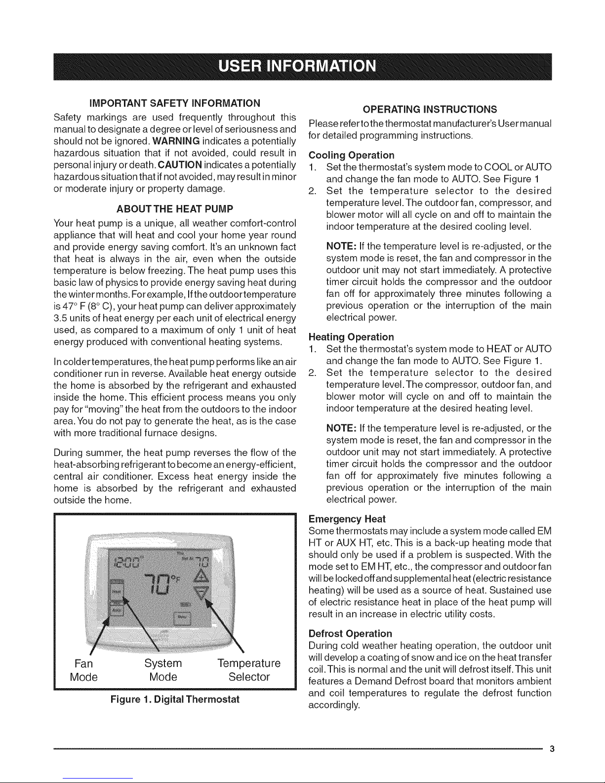
Fan System Temperature
Mode Mode Selector
Figure 1. Digital Thermostat
Emergency Heat
Some thermostats may include a system mode called EM
HT or AUX HT, etc. This is a back-up heating mode that
should only be used if a problem is suspected. With the
mode set to EM HT, etc., the compressor and outdoor fan
will be locked offand supplemental heat (electric resistance
heating) will be used as a source of heat. Sustained use
of electric resistance heat in place of the heat pump will
result in an increase in electric utility costs.
Defrost Operation
During cold weather heating operation, the outdoor unit
will develop a coating of snow and ice on the heat transfer
coil. This is normal and the unit will defrost itself. This unit
features a Demand Defrost board that monitors ambient
and coil temperatures to regulate the defrost function
accordingly.

Atthebeginningofthedefrostcycle,boththeoutdoor
condenserfan and compressorwill turn off. After
approximately30seconds,thecompressorwillturnon
andbegintoheattheoutdoorcoilcausingthe iceand
snowtomelt.
NOTE:Whiletheiceandsnowismelting,somesteam
mayrisefromtheoutdoorunitasthewarmcoilcausesthe
meltingfrosttoevaporate.Whendefrostiscompleted,the
outdoorfanmotorwillstart,andthecompressorwillturn
offagain.Inapproximately30secondsthecompressor
willstartupagainandcontinuenormaloperation.
OperatingtheHeatPump for Automatic Cooling
and Heating
HEAT PUMP MAINTENANCE
/b, CAUTION:
Shut off all electrical power to the unit before
performing any maintenance or service on the
system. Failure to comply may result in personal
injury or death.
Proper maintenance is most important to achieve the best
performance from the appliance and should be performed
by a qualified service technician at least once a year.
Follow the maintenance schedule and the instructions
below for years of safe, trouble free operation.
,
Set the thermostat system switch to AUTO and the
thermostat fan switch to AUTO. See Figure 1.
NOTE: Thermostat styles vary. Some models will
not include the AUTO mode and others will have the
AUTO in place of the HEAT and COOL. Others may
include all three. Refer to the instructions supplied
with your thermostat for specific instructions.
,
Set the thermostat temperature to the desired heating
and cooling temperatu relevel(s).The outdoor unit and
the indoor blower will then cycle on and off in either
the heating or cooling mode of operation as required
toautomatically maintain the indoor temperature within
the desired limits.
Operating the Indoor Blower Continuously
The continuous indoor blower operation istypically used to
circulate the indoorair to equalize a temperature unbalance
due to a sun load, cooking, or fireplace operation.
Set the thermostat fan mode to ON (Figure 1).The indoor
blower starts immediately, and will run continually until
the fan mode is reset to AUTO.
The continuous indoor blower operation can be obtained
with the thermostat system mode set in any position,
including OFR
Shutting the Heat Pump Off
Change the thermostat's system mode to OFF and the fan
mode to AUTO. See Figure 1. NOTE: The system will not
operate, regardless of the temperature selector setting.
Regular Cleaning
• Clean or replace the indoor air filter at the start of each
heating and cooling season, and when an accumulation
of dust and dirt is visible on the air filter.
• Remove any leaves and grass clippings from the coil
in the outdoor unit, being careful not to damage the
aluminum fins.
• Check for obstructions, such as twigs, sticks, etc.
TROUBLESHOOTING
If the unit fails to operate, check the following:
• The thermostat is properly set. See Cooling Operation
for air conditioning or Heating Operation for furnace or
air handler.
• The unit disconnect fuses are in good condition and
the electrical power to the unit is turned on.
WARRANTY INFORMATION
A warranty certificate with full details is included with the
heat pump. Carefully review these responsibilities with
your dealer or service company. The manufacturer will not
be responsible for any costs found necessary to correct
problems due to improper setup, improper installation,
adjustments, improper operating procedure on the part
of the user, etc. Some specific examples of service calls
which are not included in the limited warranty are:
• Correcting wiring problems in the electrical circuit
supplying the heat pump.
• Resetting circuit breakers or other switches.
• Adjusting or calibrating of thermostat.

IMPORTANTSAFETYINFORMATION
Safetymarkingsare usedfrequentlythroughoutthis
manualtodesignateadegreeorlevelofseriousnessand
shouldnotbeignored.WARNINGindicatesapotentially
hazardoussituationthatif notavoided,couldresultin
personalinjuryordeath.CAUTIONindicatesapotentially
hazardoussituationthatifnotavoided,mayresultinminor
ormoderateinjuryorpropertydamage.
WARNING:
Do not place combustible material on or against
the unit cabinet. Do not place combustible
materials, including gasoline and any other
flammable vapors and liquids, in the vicinity of
the unit.
WARNING:
improper installation, service, adjustment, or
maintenance may cause explosion, fire, electrical
shock or other hazardous conditions which may
result in personal injury or property damage.
Unless otherwise noted in these instructions,
only factory authorized kits or accessories may
be used with this product.
CAUTION:
This unit uses refrigerant R=410A. DO NOT use
any other refrigerant in this unit. Use of another
refrigerant will damage the unit.
WARNING:
Shut off all electrical power to the unit before
performing any maintenance or service on the
system. Failure to comply may result in personal
injury or death.
WARNING:
These units are fully charged with R=410A
refrigerant and ready for installation. When
a system is installed according to these
instructions, no refrigerant charging is required.
if repairs make it necessary for evacuation
and charging, it should only be attempted by
qualified, trained personnel thoroughly familiar
with this equipment. Some local codes require
licensed installation service personnel to
service this type of equipment. Under no
circumstances should the homeowner attempt
to install and/or service this equipment. Failure
to comply with this warning could result in
equipment damage, personal injury, or death.
WARNING:
The safety information listed below must be
followed during the installation, service, and
operation of this unit. Unqualified individuals
should not attempt to interpret these instructions
or install this equipment. Failure to follow safety
recommendations could result in possible
damage to the equipment, serious personal
injury or death.
The installer must comply with all local codes and
regulations which govern the installation of this type
of equipment. Local codes and regulations take
precedence over any recommendations contained in
these instructions. Consult local building codes and
the National Electrical Code (ANSI CI) for special
installation requirements.
This equipment contains liquid and gaseous refrigerant
under high pressure. Installation or servicing should only
be performed by qualified trained personnel thoroughly
familiar with this type equipment.
All electrical wiring must be completed in accordance
with local, state and national codes and regulations
and with the National Electric Code (ANSl/NFPA 70)
or in Canada the Canadian Electric Code Part 1 CSA
C.22.1.
Installation of equipment may require brazing
operations. Installer must comply with safety codes
and wear appropriate safety equipment (safety glasses,
work gloves, fire extinguisher, etc.) when performing
brazing operations.
Installthis unitonly ina location and position as specified
on page 6. This unit is designed only for outdoor
installations and should be located with consideration
of minimizing the length of the supply and return ducts.
Consideration should also be given to the accessibility
offuel, electric power, service access, noise, and shade.
Follow all precautions in the literature, on tags, and
on labels provided with the equipment. Read and
thoroughly understand the instructions provided with
the equipment prior to performing the installation and
operational checkout of the equipment.

GENERALINFORMATION
Thissinglepackageheatpumphasbeendesignedand
testedforcapacityandefficiencyinaccordancewithA.R.I.
Standards.Thisunitwillprovidemanyyearsofsafeand
dependablecomfort,providingitisproperlyinstalledand
maintained.Thisheatpumpisdesignedonlyforoutdoor
installations.Withregularmaintenance,this unitwill
operatesatisfactorilyyearafteryear.Abuse,improper
use,and/orimpropermaintenancecanshortenthelife
oftheapplianceandcreateunsafehazards.
Toachieveoptimumperformanceandminimizeequipment
failure,itisrecommendedthatperiodicmaintenancebe
performedon thisunit.Theabilityto properlyperform
maintenanceon this equipment requires certain
mechanical skills and tools.
Pre-lnstallation Check
Before you install this unit, the cooling load of the area
to be conditioned must be calculated and a system of
the proper capacity selected. It is recommended that
the area to be conditioned becompletely insulated and
vapor sealed.
Check the electrical supply and verify the power supply
is adequate for unit operation. If there is any question
concerning the power supply, contact the local power
company.
All units are securely packed at the time of shipment and
upon arrival should be carefully inspected for damage
prior to installing the equipment at the job site. Verify
coil fins are straight. Ifnecessary, comb fins to remove
flattened or bent fins. Claims for damage (apparent or
concealed) should be filed immediately with the carrier.
Please consult your dealer for maintenance information
and availability of maintenance contracts. Please read
all instructions before installing the unit.
Locating the Heat Pump
Survey the job site to determine the best location for
mounting the outdoor unit.
Choose an appropriate location that minimizes the
length of the supply and return air ducts.
Overhead obstructions, poorly ventilated areas, and
areas subject to accumulation of debris should be
avoided.
Sufficient clearance for unobstructed airflowthrough the
outdoorcoil must bemaintained in order to achieve rated
performance. See Figure 2 for minimum clearances to
obstructions.
Consideration should also be given to availability of
electric power, service access, noise, and shade.
Electrical power supplied to the unit must be adequate
for proper operation of the equipment. The system
must be wired and provided with circuit protection in
accordance with local building codes.
Air Ducts
This unit isdesigned only for use with a supply and return
duct. Air ducts must be installed in accordance with the
standards of the National Fire Protection Association
Standard for installation of Air Conditioning Systems
(NFPA 90A), Standard for Installation of Residence Type
Warm Air Heating and Air Conditioning Systems (NFPA
90B), and all applicable local codes. NFPA publications
are avaialable by writing to: National Fire Protection
Association, Batterymarch Park, Quincy, ME 02269 or
visit www.NFPA.org on the web.
Design the duct work according to methods described
bythe Air Conditioning Contractors of America (ACCA).
The ducts must be properly sized not to exceed .2"
W.C. pressure drop at 400 scfm per nominal ton of
cooling capacity.
Duct work should be attached directly to the unit flanges
for horizontal applications.
If roof curb is installed, the ducts must be attached to
the curb hangers, not the unit.
Unconditioned Spaces
All duct work passing through unconditioned space must
be properly insulated to minimize duct losses and prevent
condensation. Use insulation with an outer vapor barrier.
Refer to local codes for insulation material requirements.
Acoustical Duct Work
Certain installations may require the use of acoustical
lining inside the supply duct work.
Acoustical insulation must be in accordance with the
current revision of the Sheet Metal and Air Conditioning
Contractors National Association (SMACNA)
application standard for duct liners.
mmmmmmmmmmmmmmmmmmm___
36" For Coil Only 0"
' !
d3
1:3-
o 8
Z
Field Connections for Electrical Power Supply
= All wiring must comply with current provisions of the
National Electrical Code (ANSl/NFPA 70) and with
applicable local codes having jurisdiction.
= The minimum size of electrical conductors and circuit
protection must be in compliance with information listed
on the outdoor unit data label.
.......... i Minimum Required _.
Figure 2. Clearance Requirements
Clearances to ObstructionsJ
DuctliningmustbeULclassifiedbattsorblanketswith
afirehazardclassificationofFHC-25/50orless.
Fiberductworkmaybeusedinplaceofinternalduct
linersifthefiberductworkisinaccordancewiththe
currentrevisionoftheSMACNAconstructionstandard
onfibrousglassducts.Fibrousductworkandinternal
acousticalliningmustbeNFPAClass1airductswhen
testedperULStandard181forClass1ducts.
HEAT PUMP INSTALLATION
Packaging Removal
Remove the shipping carton and User's Manual from the
equipment.Take care not todamage the tubing connections
when removing the carton. Forrooftop installations,remove
and discard the two supports attached beneath the unit.
Rigging and Hoisting
Air Filter Requirements
WARNING:
Never operate the unit without a filter in place.
Dust and lint could accumulate on internal parts,
resulting in loss of efficiency, equipment damage
and possible fire.
• This unit is not supplied with air filter(s) and has no
factory equipped means for accomodating internal
filter(s). A suitable air filter must be installed upstream
of the evaporator coil of the return air system.
All return air must pass through the filters before entering
the evaporator coil. It is important that all filters be
kept clean and replaced frequently to ensure proper
operation of unit. Dirty or clogged filters will reduce the
efficiency of the unit and result in unit shutdowns.
o
Air filter pressure drop must not exceed 0.08 inchesWC.
o
Downflow Installations require an internal filter
accessory kit to be installed.
Horizontal Installations require the air filter system be
installed in the return air ductwork.
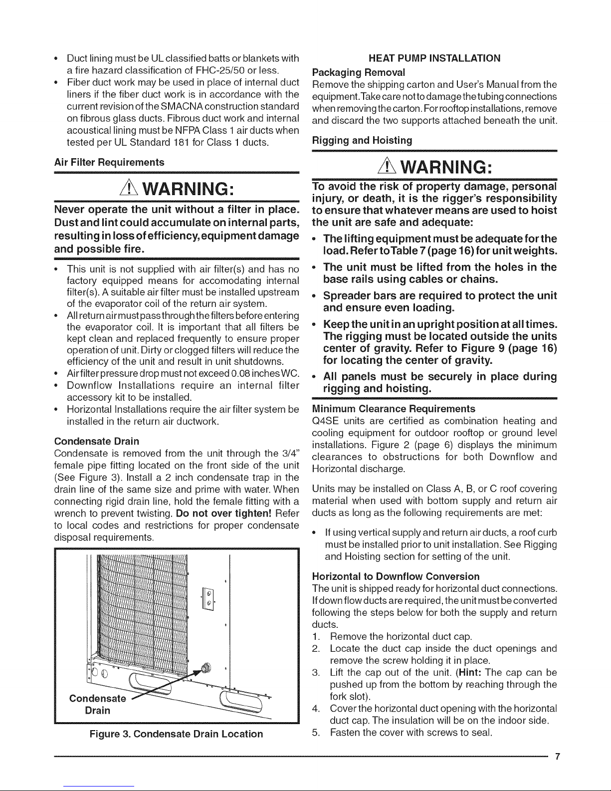
Condensate Drain
Condensate is removed from the unit through the 3/4"
female pipe fitting located on the front side of the unit
(See Figure 3). install a 2 inch condensate trap in the
drain line of the same size and prime with water. When
connecting rigid drain line, hold the female fitting with a
wrench to prevent twisting. Do not over tighten! Refer
to local codes and restrictions for proper condensate
disposal requirements.
WARNING:
To avoid the risk of property damage, personal
injury, or death, it is the rigger's responsibility
to ensure that whatever means are used to hoist
the unit are safe and adequate:
,, The lifting equipment must be adequateforthe
load. Refer toTable 7 (page 16) for unit weights.
The unit must be lifted from the holes in the
base rails using cables or chains.
Spreader bars are required to protect the unit
and ensure even loading.
Keep the unit in an upright position at all times.
The rigging must be located outside the units
center of gravity. Refer to Figure 9 (page 16)
for locating the center of gravity.
All panels must be securely in place during
rigging and hoisting.
Minimum Clearance Requirements
Q4SE units are certified as combination heating and
cooling equipment for outdoor rooftop or ground level
installations. Figure 2 (page 6) displays the minimum
clearances to obstructions for both Downflow and
Horizontal discharge.
Units may be installed on Class A, B, or C roof covering
material when used with bottom supply and return air
ducts as long as the following requirements are met:
• If using vertical supply and return air ducts, a roof curb
must be installed prior to unit installation. See Rigging
and Hoisting section for setting of the unit.
Condensate
Drain
Figure 3. Condensate Drain Location
Horizontal to Downflow Conversion
The unit is shipped ready for horizontal duct connections.
Ifdown flow ducts are required, the unit must be converted
following the steps below for both the supply and return
ducts.
1. Remove the horizontal duct cap.
2. Locate the duct cap inside the duct openings and
remove the screw holding it in place.
3. Lift the cap out of the unit. (Hint: The cap can be
pushed up from the bottom by reaching through the
fork slot).
4. Cover the horizontal duct opening with the horizontal
duct cap. The insulation will be on the indoor side.
5. Fasten the cover with screws to seal.
7

Ground Level
Ground level installations must be located according to
local building codes or ordinances and these requirements:
Clearances must be in accordance with those shown
in Figure 2 (page 6).
A suitable mounting pad (Figure 4) must be provided
and be separate from the building foundation.The pad
must be level to ensure proper condensate disposal
and strong enough to support the unit's weight. The
slab height must bea minimum of 2" (5cm) above grade
and with adequate drainage.
Ductwork should be attached directly to flanges on the
supply and return panels.
/
/
/
/,
/
/
/
/
/
Figure 4. Ground Level Installation
Rooftop
Rooftop installations must be located according to local
building codes or ordinances and these requirements:
The roof must be capable of handling the weight of the
unit. For unit weights, see Table 7 (page 16). Reinforce
the roof if necessary.
The appropriate accessory roof curb (Figure 5) must be
installed prior to unit installation.The roof curb must be
square and level to ensure proper condensate drainage.
Please follow all instructions provided with the kit.
= Secure roof curb or frame to roof using acceptable
mechanical methods per local codes. NOTE: Make sure
the two supports beneath the unit have been removed.
Roof
Curb
Figure 5. Roof Top Installation
ELECTRICAL WIRING
WARNING:
Shut off all electrical power to the unit before
performing any maintenance or service on the
system. Failure to comply may result in personal
injury or death.
Electrical connections must be in compliance with
all applicable local codes and ordinances, and with
the current revision of the National Electric Code
(ANSI/NFPA 70).
For Canadian installations the electrical connections
and grounding shall comply with the current Canadian
Electrical Code (CSA C22.1 and/or local codes).
Pre-Electrical Checklist:
Verify that the voltage, frequency, and phase of the
supply source match the specifications on the unit
rating plate.
Verify that the service provided bythe utility is sufficient
to handlethe additional load imposed bythis equipment.
refer to the unit wiring label for proper high and low
voltage wiring.
Verify factory wiring is inaccordance with the unit wiring
diagram (Figures 11 - 12, pages 18- 19). Inspect for
loose connections.
Wiring Diagram / Schematic
A wiring diagram/schematic is located onthe inside cover of
the electrical box of the outdoor unit. The installer should
become familiar with the wiring diagram/schematic before
making any electrical connections to the outdoor unit.
Line Voltage
It is recommended that the line voltage to the unit be
supplied from a dedicated branch circuit containing
the correct fuse or circuit breaker for the unit.
An electrical disconnect must be located within
sight of and readily accessible to the unit. This
switch shall be capable of electrically de-energizing the
outdoor unit. See unit data label for proper incoming field
wiring, Any other wiring methods must be acceptable
to authority having jurisdiction.
= Overcurrent protection must be provided atthe branch
circuit distribution panel and sized as shown on the unit
rating label and according to applicable local codes.
See the unit rating plate for maximum circuit ampacity
and maximum overcurrent protection limits.
Provide power supply for the unit in accordance with
the unit wiring diagram, and the unit rating plate.
Connect the line-voltage leads to the terminals on the
contactor inside the control compartment.
Use only copper wire for the line voltage power supply
to this unit as listed in Table 1 (page 10). Use proper
code agency listed conduit and a conduit connector
 Loading...