

Nordyne Q4RD 060 Installation Instructions Manual
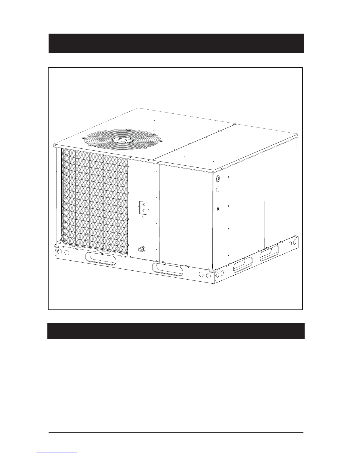
Single Package Heat Pump
Installation Instructions
TM
These instructions are primarily intended to assist qualifi ed individuals experienced in the proper installation of heating and/or air conditioning appliances.
Some local codes require licensed installation/service personnel for this type
equipment. All installations must be in accordance with these instructions and
with all applicable national and local codes and standards.
Read these instructions thoroughly before starting the installation. Follow all
precautions and warnings contained within these instructions and on the unit.
IMPORTANT

2
SECTION 1. OWNER INFORMATION
5
4
2
3
1
6
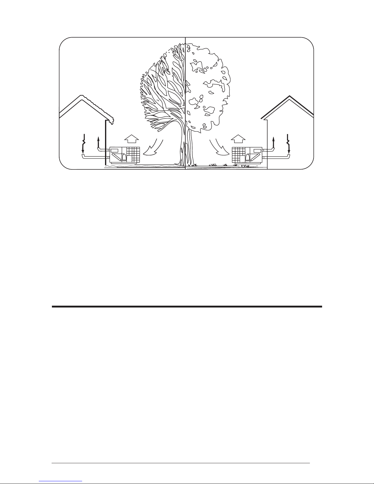
WINTER HEATING
1. Outdoor air enters the heat pump.
2. The cold, heat-transfer section (outdoor coil)
extracts the heat from the air as the refrigerant
evaporates from a liquid to a cold gas.
3. The refrigerant, compressed to a hot gas by
the heat pump, carries the heat to the heattransfer section (indoor coil).
4. The hot, heat-transfer section (indoor
coil) releases the heat as the refrigerant
condenses from a gas to a liquid.
5. The blower circulates the heat throughout
the home via the supply duct.
6. The refrigerant returns to the outdoor coil
and evaporates once again to absorb more
heat.
It is the sole responsibility of the homeowner to
make certain that heat pump has been correctly
set up and adjusted to operate properly.
5
4
3
6
2
1
SUMMER COOLING
1. Indoor air enters the return air duct.
2. The cold, heat-transfer section (indoor coil)
extracts the heat from the air as the refrigerant
evaporates from a liquid to a cold gas.
3. The refrigerant, drawn to the heat pump and
compressed to a hot gas, carries the heat
outdoors.
4. The hot, heat-transfer section (outdoor coil)
releases the heat as the refrigerant condenses
from a gas to a liquid.
5. The heat pump (outdoor fan) discharges the
heat to the outside air.
6. The refrigerant returns to the indoor coil
and evaporates once again to absorb more
heat.
2. Resetting circuit breakers or other switches.
3. Adjusting or calibrating of thermostat.
The Manufacturer warrants the heat pump to be
free from defects in material or workmanship for a
period of one year. We will not be responsible for
any costs found necessary to correct problems
due to improper setup, improper installation,
adjustments, improper operating procedure on
the part of the user, etc.
Some specifi c examples of service calls which
are not included in the limited warranty are:
1. Correcting wiring problems in the electrical
circuit supplying the heat pump.
To avoid misunderstandings at a later date,
carefully review these responsibilities with your
dealer or service company.
The heat pump system will heat and cool your
home and save your energy dollars.
During the summer, a heat pump cools a house
by absorbing heat from within the house and
exhausting it outdoors. During the winter, a heat
pump heats a house by absorbing heat outdoors
and exhausting it indoors. This is an effi cient
heating means because you pay for “moving”
heat from outdoors to indoors, but do not pay
to generate the heat.
3
OPERATING INSTRUCTIONS
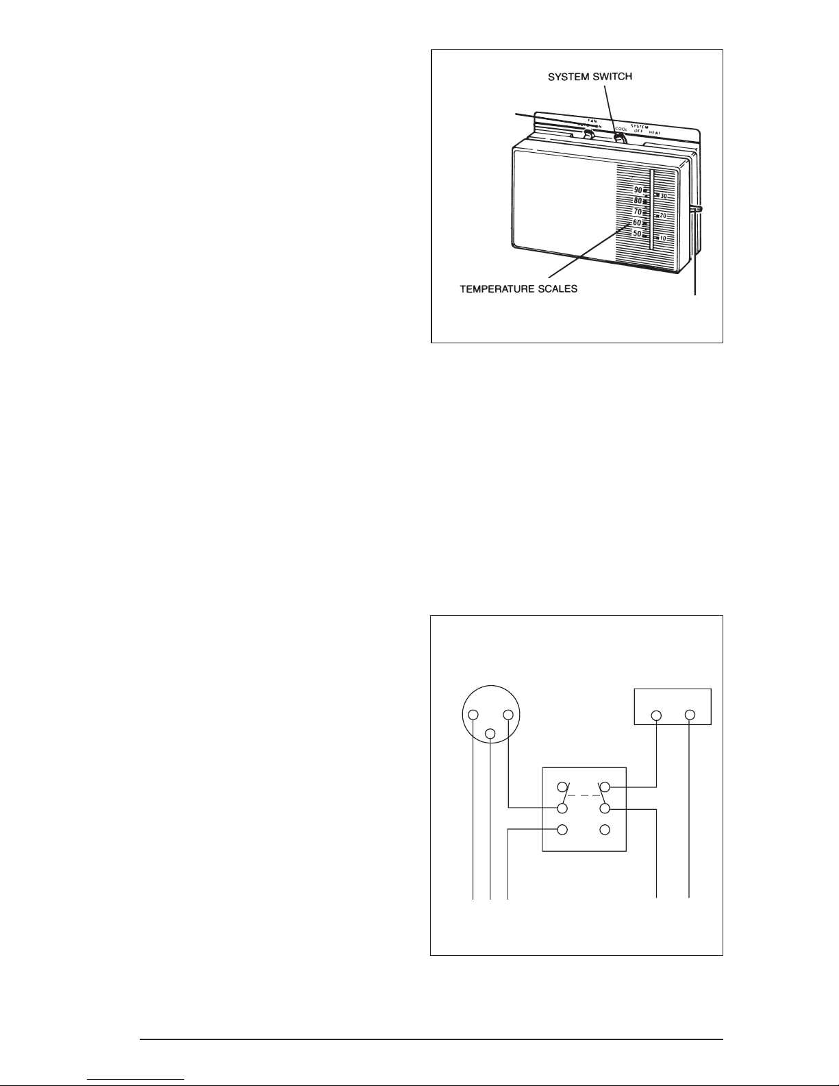
To Operate Your Heat Pump For Cooling —
1. Set the thermostat system switch to COOL
and the thermostat fan switch to AUTO. See
Figure 1.
2. Set the thermostat temperature selector to the
desired cooling temperature. The outdoor unit
fan, the indoor blower, and the compressor
will all cycle on and off to maintain the indoor
temperature at the desired cooling level.
FAN SWITCH
NOTE: If the thermostat temperature level is
re-adjusted, or if the thermostat system switch
is re-positioned, the outdoor unit fan and the
compressor may not start immediately. A
protective timer circuit holds the compressor and
the outdoor fan off for approximately six minutes
following a previous operation or the interruption
of the main electric power
To Operate Your Heat Pump For Heating —
1. Set the thermostat system switch for HEAT
and the thermostat fan switch to AUTO. See
Figure 1.
2. Set the thermostat temperature selector to the
desired heating temperature. The outdoor unit
fan, the indoor blower, and the compressor
will all cycle on and off to maintain the indoor
temperature at the desired heating level.
NOTE: If the thermostat temperature level is
re-adjusted, or if the thermostat system switch
is re-positioned, the outdoor unit fan and the
compressor may not start immediately. A
protective timer circuit holds the compressor and
the outdoor fan off for approximately six minutes
following a previous operation or the interruption
of the main electrical power.
TEMPERATURE SELECTOR
Figure 1. Typical Thermostat
Defrost — During cold weather heating operation,
the outdoor unit will develop a coating of snow
and ice on the heat transfer coil. This is normal
and the unit will periodically defrost itself. During
the defrost cycle, the outdoor fan will stop, while
the compressor continues to run and heat the
outdoor coil, causing the snow and ice to melt.
During defrost, there may be some steam rise
from the outdoor unit as the warm coil causes
some melted frost to evaporate.
Cooling
Thermostat
R
Furnace
Thermostat
R
Emergency Heat — Some thermostats will
include a system switch position termed EM
HT or AUX HT, etc. This is a back-up heating
mode to be used only if there is a suspected
problem. With the system switch set to EM
HT, etc., the compressor and outdoor fan will
be locked off and supplemental heat (electric
resistance heating) will be used as a source of
heat. Sustained use of electric resistance heat in
place of the heat pump will result in an increase
in electric utility costs.
4
Double Throw
Double Pole Switch
To Air Conditioner
To Furnace
Figure 2. Thermostat Interlock System
SPECIFICATIONS
Single Package Heat Pumps are designed for
outdoor rooftop or ground level slab installations.
The units are shipped ready for horizontal duct
connections and are easily converted for down
fl ow applications.
All Q4RD models are shipped from the factory
with the following:
1. Zero clearance to combustibles
2. Multi-speed direct-drive blower.
3. Compressor Anti-short-cycle timer for single
phase models.
4. Blower Speed Relay.
5. Horizontal or Down fl ow duct connections.
6. Square-to-round adapter boxes with 14”
collars for supply and return openings.
The unit dimensions are shown in Figure 3.
WARNING:
The square-to-round adapter boxes
and 14” collars are shipped inside the
return inlet. These must be removed
before the unit is run.
Optional fi eld-installed electric heater kits are
available in 5 kw through 20 kw heating capacities.
A separate installation instruction document
for the electric heaters and their application
accompanies this one. A two stage heat 24VAC
thermostat should be used with electric heater
kits installed.
SAFETY CONSIDERATIONS
It is the responsibility of the installer to ensure
that the installation is made in accordance with
all applicable local and national codes.
Labels, Tags — When working with this
equipment, follow all precautions in the literature,
on tags, and on labels provided with the unit
and/or approved fi eld installed kits. The type
of hazard and severity are described on each
label or tag.
Pressures Within The System — This
equipment contains liquid and gaseous
refrigerant under high pressure. Installation or
servicing should only be performed by qualifi ed
trained personnel thoroughly familiar with this
type equipment.
INSTALLATION REQUIREMENTS
Equipment Check — Before beginning the
installation, verify that the unit model is correct for
the job. The unit model number is printed on the
data label. All units have been securely packaged
at the point of shipment. After unpacking the unit,
carefully inspect it for apparent and concealed
damage. Claims for damage should be fi led with
the carrier by the consignee.
Requirements and Codes — The installer
must comply with all local codes and regulations
which govern this type equipment. Local codes
and regulations take precedence over any
recommendations contained in these instructions.
All electrical wiring must be made in accordance
with local codes and regulations and with the
National Electric Code (ANSI/NFPA 70) or in
Canada the Canadian Electric Code Part 1 CSA
C.22.1. Air Ducts must be installed in accordance
with the standards of the National Fire Protection
Association “Standards for Installation of Air
Conditioning and Ventilation Systems” (NFPA
90A), “Standard for Installation of Residence
Type Warm Air Heating and Air Conditioning
Systems” (NFPA 90B), these instructions and
all applicable local codes.
WARNING:
Improper installation, service,
adjustment, or maintenance may cause
explosion, fi re, electrical shock or other
hazardous conditions which may result
in personal injury or property damage.
Unless otherwise noted in these
instructions, only factory authorized
kits or accessories may be used with
this product. Noncompliance may void
the unit’s warranty.
NFPA publications are available by writing:
National Fire Protection Association
Batterymarch Park
Quincy, Maine 02269
IMPORTANT: Do Not Place Unit Under The
Home.
Unit Location — This heat pump is designed only
for outdoor installations. Choosing the location of
the unit should be based on minimizing the length
5
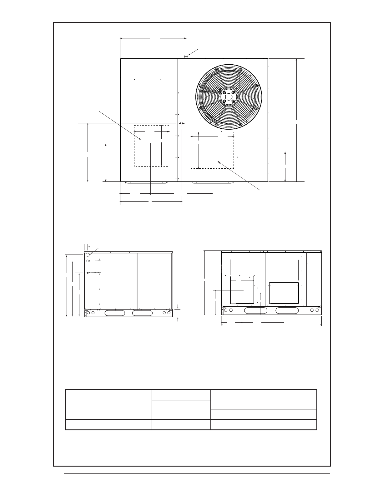
DOWNFLOW
SUPPLY DUCT
OPENING
24.9
3/4" NPT Female
Drain Connector
47.5
13.5
16.0
CG
16.0
13.5
B
13.3
12.0
23.5
A
DOWNFLOW
RETURN DUCT
OPENING
12.0
Top View
1.8
1.75 Ø Power Entry (Capped)
1.25 Ø Power Entry
30
27.2
23.6
0.88 Ø Control Wiring Entry
C
14.7
5.0
SUPPLY
13.5
16.0
13.45
RETURN
16.0
8
13.5
4.0
CONDENSING
COIL
Side View
Model Number
Q4RD
060 580 29.5 26.0 43.0 39.3
6
Unit
Weight
4.00
11.75 22.75
55.8
Back View
Center of Gravity Height (in inches)
ABCwith base rails without base rails
Figure 3. Dimensions
 Loading...