

Page 1
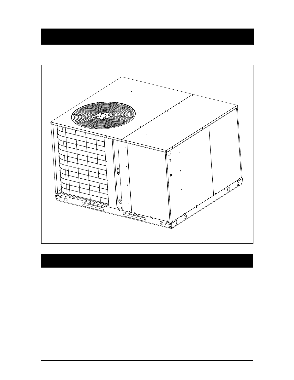
Single Package Heat Pump
Installation Instructions
460 Volt Q4 Series
IMPORTANT
Read these instructions thoroughly before starting the installation. Follow
all precautions and warnings contained within these instructions and on
the unit.
These instructions are primarily intended to assist qualified individuals
experienced in the proper installation of heating and/or air conditioning
appliances. Some local codes require licensed installation/service personnel for this type equipment. All installations must be in accordance
with these instructions and with all applicable national and local codes
and standards.
Page 2

TABLE OF CONTENTS
OWNER INFORMATION .......................................................................................................... 3
SPECIFICATIONS..................................................................................................................... 4
SAFETY CONSIDERATIONS................................................................................................... 5
• Labels, Tags................................................................................................................ 5
• Pressures Within The System..................................................................................... 5
INSTALLATION REQUIREMENTS .......................................................................................... 5
• Equipment Check........................................................................................................ 5
• Requirements and Codes ........................................................................................... 5
• Unit Location ............................................................................................................... 5
• Air Filters ..................................................................................................................... 5
• Condensate Drain ....................................................................................................... 5
UNIT INSTALLATION............................................................................................................... 7
• Ground Level............................................................................................................... 7
• Rigging and Hoisting................................................................................................... 7
• Rooftop........................................................................................................................ 7
AIR DUCTS ............................................................................................................................... 7
• Unconditioned Spaces. ............................................................................................... 7
• Acoustical Duct Work .................................................................................................. 8
• Horizontal to Down flow Conversion........................................................................... 8
• Clearance .................................................................................................................... 8
ELECTRICAL WIRING ............................................................................................................. 8
• Line Voltage ................................................................................................................ 8
• Blower Speed.............................................................................................................. 9
• Low Voltage Connections ........................................................................................... 9
• Room Thermostat ....................................................................................................... 9
• Defrost Cycle Timer .................................................................................................... 9
START-UP AND SYSTEM CHECK ........................................................................................ 10
• Air Circulation ............................................................................................................ 10
• System Cooling ......................................................................................................... 10
• System Heating......................................................................................................... 10
UNIT MAINTENANCE............................................................................................................. 11
• Refrigerant Charging................................................................................................. 11
• Routine Maintenance ................................................................................................ 11
BLOWER TABLE .................................................................................................................... 12
CHARGING CHARTS ........................................................................................................ 13-16
ACCESSORY KIT TABLE ...................................................................................................... 17
WIRING DIAGRAM ................................................................................................................. 18
2
Page 3
SECTION 1. OWNER INFORMATION
5
4
2
3
6
1
WINTER HEATING
1. Outdoor air enters the heat pump.
2. The cold, heat-transfer section (outdoor coil)
extracts the heat from the air as the refrigerant
evaporates from a liquid to a cold gas.
3. The refrigerant, compressed to a hot gas by
the heat pump, carries the heat to the heattransfer section (indoor coil).
4. The hot, heat-transfer section (indoor coil)
releases the heat as the refrigerant condenses
from a gas to a liquid.
5. The blower circulates the heat throughout
the home via the supply duct.
6. The refrigerant returns to the outdoor coil and
evaporates once again to absorb more heat.
It is the sole responsibility of the homeowner to
make certain that heat pump has been correctly
set up and adjusted to operate properly.
5
4
3
6
2
1
SUMMER COOLING
1. Indoor air enters the return air duct.
2. The cold, heat-transfer section (indoor coil)
extracts the heat from the air as the refrigerant
evaporates from a liquid to a cold gas.
3. The refrigerant, drawn to the heat pump and
compressed to a hot gas, carries the heat
outdoors.
4. The hot, heat-transfer section (outdoor coil)
releases the heat as the refrigerant condenses
from a gas to a liquid.
5. The heat pump (outdoor fan) discharges the
heat to the outside air.
6. The refrigerant returns to the indoor coil and
evaporates once again to absorb more heat.
2. Resetting circuit breakers or other switches.
3. Adjusting or calibrating of thermostat.
NORDYNE warrants the heat pump to be free
from defects in material or workmanship for a
period of one year. A warranty certificate with
full details is included with the heat pump. However, NORDYNE will not be responsible for any
costs found necessary to correct problems due
to improper setup, improper installation, adjustments, improper operating procedure on the
part of the user, etc.
Some specific examples of service calls which
are not included in the limited warranty are:
1. Correcting wiring problems in the electrical
circuit supplying the heat pump.
To avoid misunderstandings at a later date,
carefully review these responsibilities with your
dealer or service company.
The heat pump system will heat and cool your
home and save your energy dollars.
During the summer, a heat pump cools a house
by absorbing heat from within the house and
exhausting it outdoors. During the winter, a heat
pump heats a house by absorbing heat outdoors
and exhausting it indoors. This is an efficient
heating means because you pay for “moving”
heat from outdoors to indoors, but do not pay to
generate the heat.
3
Page 4
OPERATING INSTRUCTIONS
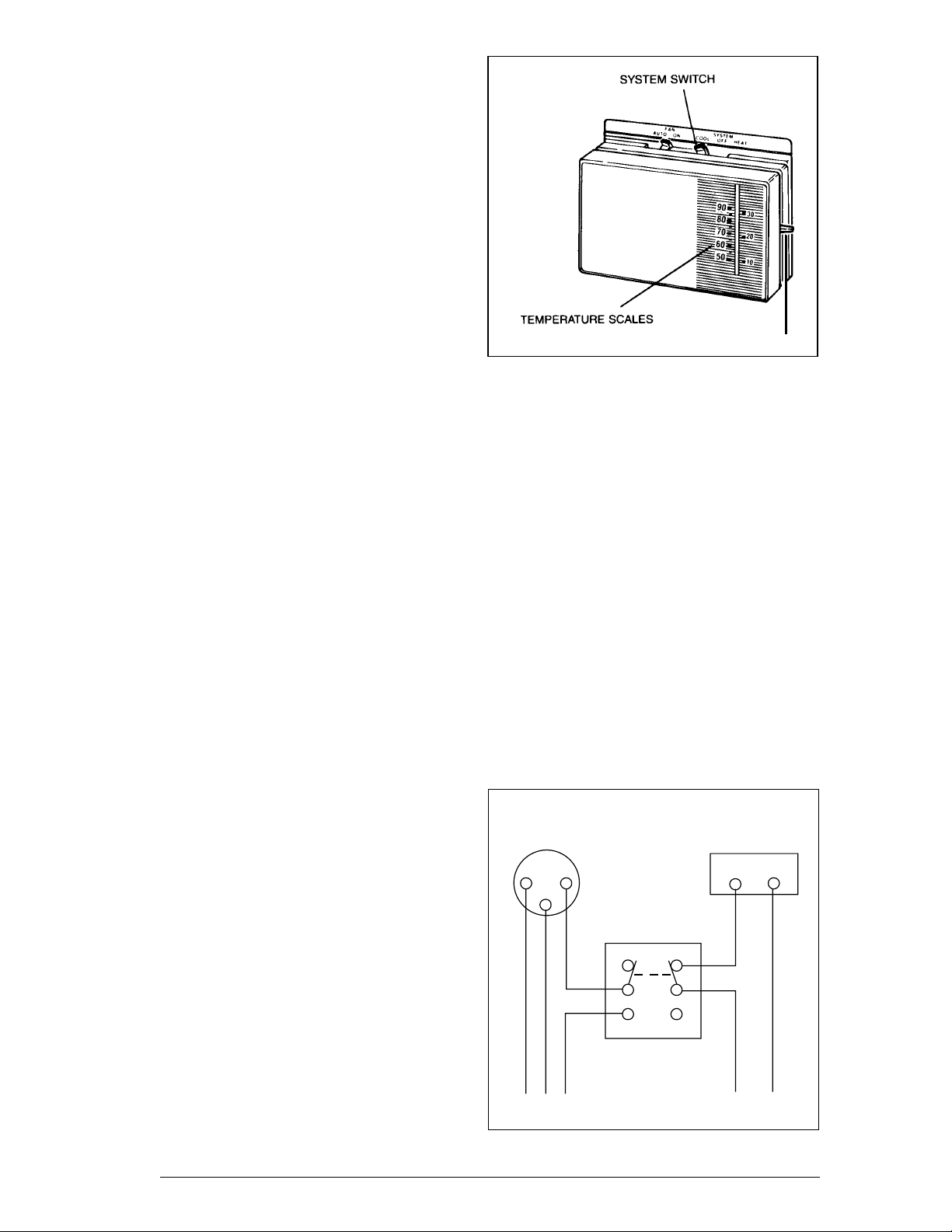
To Operate Your Heat Pump For Cooling —
1. Set the thermostat system switch to COOL
and the thermostat fan switch to AUTO. (See
Figure 1)
2. Set the thermostat temperature selector to
the desired cooling temperature. The outdoor
unit fan, the indoor blower, and the
compressor will all cycle on and off to maintain
the indoor temperature at the desired cooling
level.
NOTE: If the thermostat temperature level is readjusted, or if the thermostat system switch is repositioned, the outdoor unit fan and the
compressor may not start immediately. A
protective timer circuit holds the compressor
and the outdoor fan off for approximately six
minutes following a previous operation or the
interruption of the main electric power
To Operate Your Heat Pump For Heating —
1. Set the thermostat system switch for HEAT
and the thermostat fan switch to AUTO. (See
Figure 1)
2. Set the thermostat temperature selector to
the desired heating temperature. The outdoor
unit fan, the indoor blower, and the
compressor will all cycle on and off to
maintain the indoor temperature at the desired
heating level.
FAN SWITCH
TEMPERATURE SELECTOR
Figure 1. Typical Thermostat
Defrost — During cold weather heating
operation, the outdoor unit will develop a coating
of snow and ice on the heat transfer coil. This is
normal and the unit will periodically defrost itself.
During the defrost cycle, the outdoor fan will
stop, while the compressor continues to run and
heat the outdoor coil, causing the snow and ice
to melt. During defrost, there may be some
steam rise from the outdoor unit as the warm coil
causes some melted frost to evaporate.
SPECIFICATIONS
Model Series Q4 Single Package Heat Pumps
are designed for outdoor rooftop or ground level
slab installations. The units are shipped ready
for horizontal duct connections and are easily
converted for down flow applications.
NOTE: If the thermostat temperature level is readjusted, or if the thermostat system switch is repositioned, the outdoor unit fan and the
compressor may not start immediately. A
protective timer circuit holds the compressor
and the outdoor fan off for approx-imately six
minutes following a previous operation or the
interruption of the main electrical power.
Emergency Heat — Some thermostats will
include a system switch position termed EM HT
or AUX HT, etc. This is a back-up heating mode
to be used only if there is a suspected problem.
With the system switch set to EM HT, etc., the
compressor and outdoor fan will be locked off
and supplemental heat (electric resistance
heating) will be used as a source of heat.
Sustained use of electric resistance heat in
place of the heat pump will result in an increase
in electric utility costs.
4
Cooling
Thermostat
R
Double Throw
Double Pole Switch
To Heat Pump
Furance
Thermostat
R
To Furance
Figure 2. Thermostat Interlock System
Page 5
All models are shipped from the factory with the
following:
1. Zero clearance to combustibles
2. Multi-speed direct-drive blower.
3. Blower Speed Relay.
4. Horizontal or Down flow duct connections.
for the job. The unit model number is printed on
the data label. All units have been securely
packaged at the point of shipment. After
unpacking the unit, carefully inspect it for
apparent and concealed damage. Claims for
damage should be filed with the carrier by the
consignee.
The unit dimensions are shown in Figure 3.
Optional field-installed electric heater kits are
available in 9 kw and 15 kw heating capacities.
A separate installation instruction document for
the electric heaters and their application
accompanies this one. A two stage heat 24VAC
thermostat should be used with electric heater
kits installed.
SAFETY CONSIDERATIONS
It is the responsibility of the installer to ensure
that the installation is made in accordance with
all applicable local and national codes.
!
WARNING:
Improper installation, service,
adjustment, or maintenance may cause
explosion, fire, electrical shock or other
hazardous conditions which may result
in personal injury or property damage.
Unless otherwise noted in these
instructions, only factory authorized
kits or accessories may be used with
this product. Noncompliance may void
the unit’s warranty.
Labels, Tags — When working with this
equipment, follow all precautions in the
literature, on tags, and on labels provided with
the unit and/or approved field installed kits.
The type of hazard and severity are described
on each label or tag.
Pressures Within The System — This
equipment contains liquid and gaseous
refrigerant under high pressure. Installation or
servicing should only be performed by qualified
trained personnel thoroughly familiar with this
type equipment.
INSTALLATION REQUIREMENTS
Equipment Check — Before beginning the
installation, verify that the unit model is correct
Requirements and Codes — The installer must
comply with all local codes and regulations
which govern this type equipment. Local codes
and regulations take precedence over any
recommendations contained in these
instructions. All electrical wiring must be made
in accordance with local codes and regulations
and with the National Electric Code (ANSI/NFPA
70) or in Canada the Canadian Electric Code
Part 1 CSA C.22.1. Air Ducts must be installed
in accordance with the standards of the National
Fire Protection Association “Standards for
Installation of Air Conditioning and Ventilation
Systems” (NFPA 90A), “Standard for Installation
of Residence Type Warm Air Heating and Air
Conditioning Systems” (NFPA 90B), these
instructions and all applicable local codes.
NFPA publications are available by writing:
National Fire Protection Association
Batterymarch Park
Quincy, Maine 02269
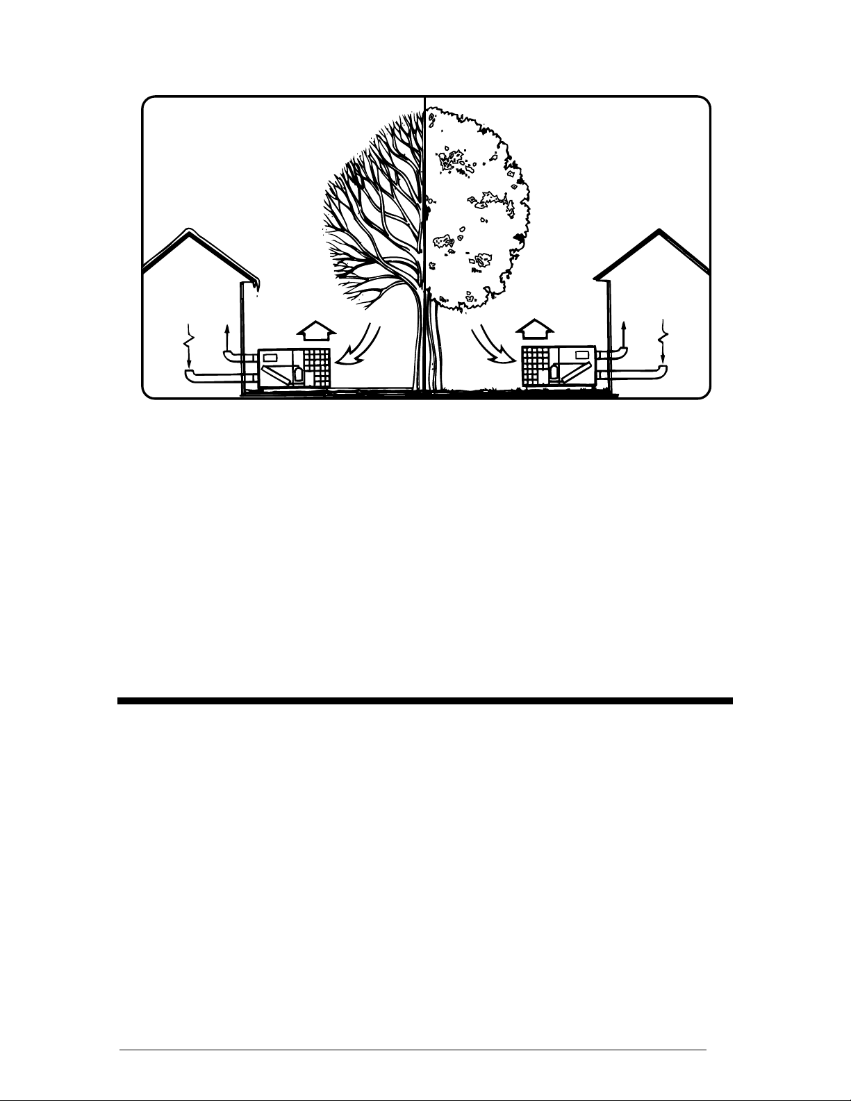
Unit Location — The Q4 series heat pump is
designed only for outdoor installations. Choosing
the location of the unit should be based on
minimizing the length of the supply and return
ducts. Consideration should also be given to
availability of electric power, service access,
noise, and shade. Sufficient clearance for
unobstructed airflow through the outdoor coil
must be maintained in order to achieve rated
performance See Figure 4 for minimum
clearances to obstructions.
Air Filters — A suitable air filter must be installed
in the return air system. Air filter pressure drop
must not exceed 0.08 inches w.c. at 300 fpm.
Condensate Drain — Condensate is removed
from the unit through the 3/4" female pipe fitting
located on the front side of the unit. (See Figure
5.) Install a 2 inch condensate trap in the drain
line of the same size and prime with water.
When connecting rigid drain line, hold the female
fitting with a wrench to prevent twisting. Do not
over tighten! Refer to local codes and
restrictions for proper condensate disposal
requirements.
5
Page 6
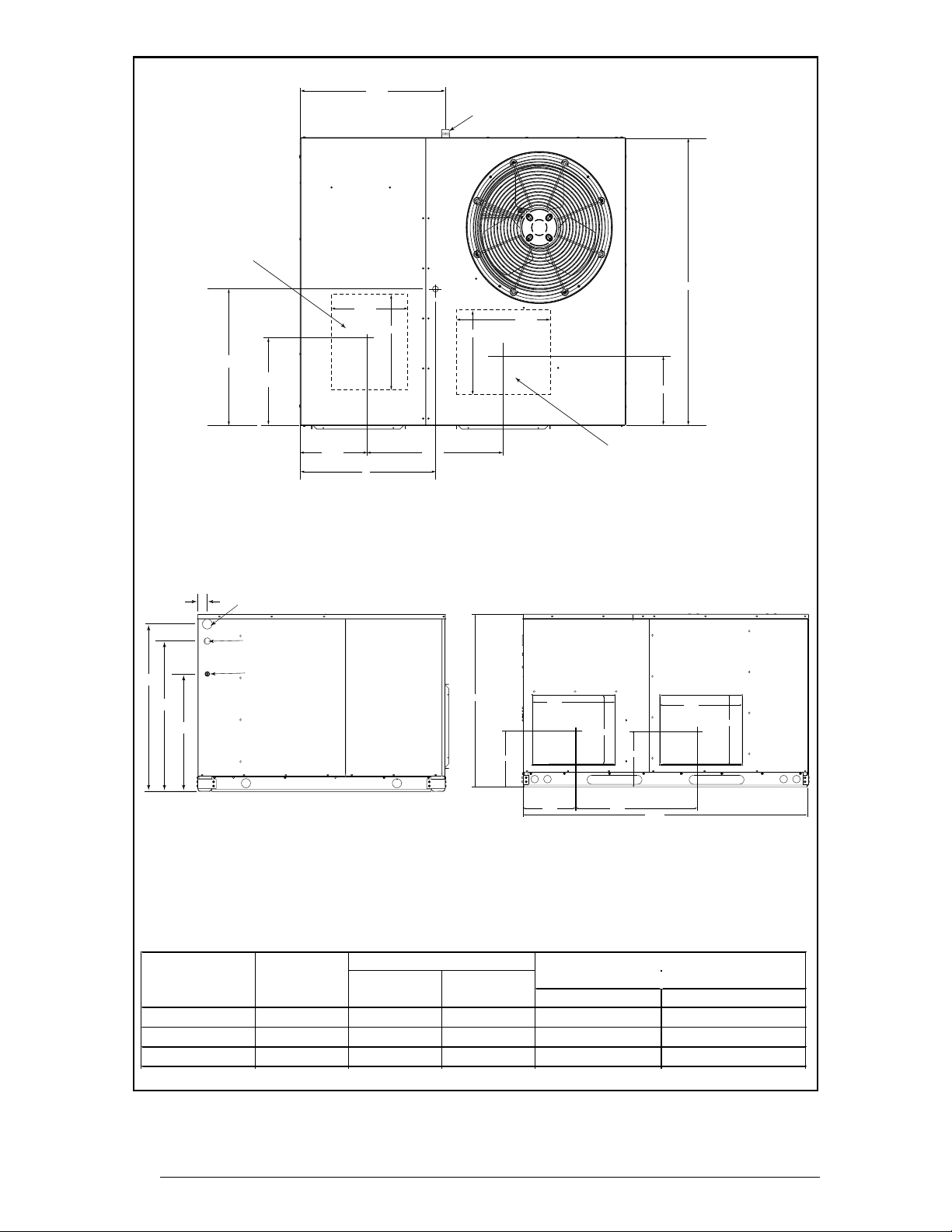
SUPPLY
24.9
3/4" NPT Female
Drain Connector
28.7
26.0
22.4
B
1.8
1.75 Ø Power Entry (Capped)
1.25 Ø Power Entry
13.3
0.88 Ø Control Wiring Entry
13.5
A
16.0
23.512.0
Top View
CG
13.5
47.5
16.0
12.0
RETURN
C
11.2
SUPPLY RETURN
16.0
13.5
11.2
16.0
13.5
10.0 24.9
55.8
Side View Back View
Model No.
Unit
Weight
Q4SA-036 340 28.0 26.0 33.7 31.3
Q4SA-048 345 28.0 26.0 33.7 31.3
Q4SA-060 400 29.5 26.5 37.7 35.3
6
Center of Gravity Height (in inches)
AB
with base rails without base rails
C
Figure 3. Dimensions
Page 7

36"
36"
72"
36"
6"
Figure 4. Minimum Clearances
UNIT INSTALLATION
Ground Level — When installing the unit at
ground level, provide a concrete mounting pad
separate from the building foundation. The pad
must be level to insure proper condensate
disposal and strong enough to support the unit’s
weight. Refer to Figure 3. Make sure the slab
is a minimum of 2" above the grade and in an
area that drains well (See Figure 6).
Rigging and Hoisting — The unit should be
lifted using slings and spreader bars. The
spreader bars are necessary to prevent damaging
the top of the unit’s cabinet. Make sure that the
lifting equipment is adequate for the load. Refer
to Figure 3 for unit weights. Keep the unit in an
upright position at all times.
!
WARNING:
To avoid the risk of property damage or
personal injury; it is the rigger’s
responsibility to insure that whatever
means are used to hoist the unit are
safe and adequate.
Condensate Drain
Figure 5. Condensate Drain
Rooftop — For rooftop installations use the
appropriate accessory roof curb and follow all
instructions included with it. Locate the unit
according to local building codes and ordinances.
The curb must be level to insure proper
condensate drainage (See Figure 7).
The roof must be capable of handling the weight
of the unit. (See Figure 3) for unit weights.
Reinforce the roof if required.
AIR DUCTS
This unit is designed only for use with a
supply and return duct. Air ducts should be
installed in accordance with the standards of
the National Fire Protection Association
“Standard for Installation of Air Conditioning
Systems” (NFPA 90A), “Standard for
Installation of Residence Type Warm Air
Heating and Air Conditioning Systems” (NFPA
90B), and all applicable local codes.
Design the duct work according to methods
described by the National Warm Air Heating and
Air Conditioning Association (ACCA). The ducts
must be properly sized not to exceed .2" w.c.
pressure drop at 400 scfm per nominal ton of
cooling capacity.
!
CAUTION:
All panels must be securely in place
when rigging and hoisting.
The rigging must be located outside the unit’s
center of gravity. Refer to Figure 3 for center of
gravity locations.
Duct work should be attached directly to the unit
flanges for horizontal applications. On roof curb
installations the ducts must be attached to the
curb hangers, not the unit.
Unconditioned Spaces — All duct work passing
through unconditioned space must be properly
insulated to minimize duct losses and prevent
condensation. Use insulation with an outer
vapor barrier. Refer to local codes for insulation
material requirements.
7
Page 8

Acoustical Duct Work — Certain installations
may require the use of acoustical lining inside
the supply duct work. Acoustical insulation must
be in accordance with the current revision of the
Sheet Metal and Air Conditioning Contractors
National Association (SMACNA) application
standard for duct liners. Duct lining must be UL
classified batts or blankets with a fire hazard
classification of FHC-25/50 or less. Fiber duct
work may be used in place of internal duct liners
if the fiber duct work is in accordance with the
current revision of the SMACNA construction
standard on fibrous glass ducts. Fibrous duct
work and internal acoustical lining must be NFPA
Class 1 air ducts when tested per UL Standard
181 for Class 1 ducts.
Horizontal to Down flow Conversion — The
unit is shipped ready for horizontal duct
connections. If down flow ducts are required,
the unit must be converted following the steps
below for both the supply and return ducts.
1) Locate the duct cap inside the duct openings
and remove the screw holding it in place.
2) Lift the cap out of the unit. (The cap can be
pushed up from the bottom by reaching
through the fork slot).
3) Cover the horizontal duct opening with the
cap. The insulation will be on the indoor side.
4) Fasten the cover with screws and seal to
prevent air leakage.
Clearance — The Q4 Series is approved for 0
inch clearance.
ELECTRICAL WIRING
General — Electrical power wiring must be
made in accordance with all applicable local
codes and ordinances, and with the current
revision of the National Electric Code NFPA 70
or in Canada CSA C.22.1 - Canadian Electrical
Code Part 1. If any of the original wire as
supplied with the unit must be replaced, it must
be replaced with material of the same gage and
temperature rating.
Line Voltage — Before proceeding with the
electrical connections, make certain that the
voltage, frequency, and phase of the supply
source are the same as those specified on the
unit rating plate. Also verify that the service
provided by the utility is sufficient to handle the
additional load imposed by this equipment.
!
WARNING:
To avoid the risk of electrical shock,
personal injury, or death, disconnect
all electrical power to the unit before
performing any maintenance or service.
The unit may have more than one
electrical power supply.
See Figure 8 or the unit wiring label for proper
high and low voltage wiring. Make all electrical
connections in accordance with all applicable
codes and ordinances.
Figure 6. Ground Level Installation
8
2"
Figure 7. Roof Top Installation
Page 9

Use a separate branch electrical circuit for this
unit. A means of electrical disconnect must be
located within sight of and readily accessibility
to the unit. Internally mounted circuit breakers
are available as field installed options. These
circuit breakers can be used as an electrical
disconnect.
Provide power supply (or supplies) for the unit in
accordance with the unit wiring diagram, and
the unit rating plate. Connect the line-voltage
leads to the corresponding terminals on the
contactor (or the circuit breaker when the field
installed circuit breaker kits are used) inside the
control compartment. Use only copper wire for
the line voltage power supply to this unit. Use
proper code agency listed conduit and a conduit
connector for connecting the supply wires to the
unit and for obtaining proper grounding.
Grounding may also be accomplished by using
the grounding lug provided in the control box.
!
WARNING:
The unit cabinet must have and
uninterrupted or unbroken electrical
ground to minimize personal injury if an
electrical fault should occur. This
ground may consist of electrical wire or
approved conduit when installed in
accordance with existing national or
local codes.
Blower Speed — The blower speed is preset at
the factory for operation at the same speed for
heating and cooling. For optimum system
performance and comfort, it may be necessary
to change the factory set speed. To change the
blower speed:
1. Disconnect all electrical power to the unit
and remove the service panel.
2. Cut the wire tie holding the motor lead
bundle. See Figure 9 for detailed
information on the appropriate model and
speed desired.
3. If the desired heating blower speed is
different than the cooling speed, remove
and discard the jumper wire between
terminals #6 and #4. on the blower relay.
Place the desired heating blower speed
lead on terminal #6 and the desired
cooling blower speed lead on terminal
#4 of the blower relay. Use another wire
tie (field supplied) to bundle the
remaining motor leads.
!
CAUTION:
To avoid personal injury or property
damage, make certain that the motor
leads cannot come into contact with
any uninsulated metal components of
the unit.
Check all factory wiring per the unit wiring
diagram and inspect the factory wiring
connections to be sure none loosened during
shipping or installation.
Low Voltage Connections
Room Thermostat — Several options are avail-
able for a room thermostat depending on the
accessories installed with the unit. The available thermostats recommended for use with the
Q4 units are listed with the accessories in Table
5. Select a thermostat which operates in conjunction with the installed accessories. The
thermostat should be mounted about five feet
above the ground on an inside wall. The thermostat should be kept away from drafts, slamming doors, lamps, direct sunlight, or in line with
the supply air flow.
To install the thermostat:
1. Position the sub base on an inside wall and
mark the mounting holes and thermostat
cable openings.
2. Cut out the cable opening and route the
thermostat cable from the unit’s low voltage
compartment to the thermostat location.
The thermostat cable is supplied by the
installer.
3. Connect the cable leads to the sub base or
thermostat terminals and to the unit’s low
voltage pigtails as shown in Figure 10. A
system wiring diagram is also provided on
the inside of the control panel cover and in
Figure 8 of these installation instructions.
4. Secure sub base or thermostat to the wall
using screws provided with the thermostat.
5. If sub base is used, install the correct
thermostat housing to sub base.
6. Refer to thermostat instruction sheet for
complete detailed mounting information.
Defrost Cycle Timer — The defrost cycle timer
controls the time interval of the hot gas defrost
after the defrost sensor closes. It is located in
the lower left corner of the defrost control board
on the low voltage side of the control box. Three
9
Page 10

interval settings are available: 30 minutes, 60
minutes, and 90 minutes. Time setting selection
is dependent on the climate where the unit is
being installed.
Example 1. Dry climate of Southern
Arizona. A 90 minute setting is
recommended.
Example 2. Moist climate of Seattle,
Washington. A 30 minute setting is
recommended.
To set the cycle timer, place the timing pin on the
defrost control board to the desired time interval
post.
• Verify that all exterior panels are replaced
and securely fastened.
• Verify that the outdoor fan turns freely.
• Verify that the power supply branch circuit
overcurrent protection is sized properly.
• Verify that the thermostat is wired correctly.
The thermostat function switch should be
set to “Off’ and the thermostat fan switch
should be set to “Auto.”
Start-Up Procedure
Close all electrical disconnects to energize the
system.
!
WARNING:
Note: All units are shipped from the factory with
the default time setting of 30 minutes.
START UP AND SYSTEM CHECK
Pre-Start Check List
• Verify that the unit is level to allow proper
condensate drainage.
• Verify that there is free airflow to and from
the outdoor coil and that all clearance
requirements are met.
• Verify that the duct work is sealed to prevent
air leakage.
• Verify that the line voltage power leads are
securely connected and the unit is properly
grounded.
• Verify that the low voltage wires are securely
connected to the correct leads on the low
voltage terminal strip.
Q4SA-048D & Q4SA-060D Blower Wiring
Blower Speed
Blower Leads Low Medium High
Red BR T3 TB T1 TB T2
Black BR T6 BR T6 BR T3
Gray BR T4 BR T4 BR T6
Blue TB T1 BR T3 BR T5
Violet TB T1 TB T2 TB T1
BR T ( ) - Blo wer Re l a y T ermin al (number)
TB T( ) - T e rm inal Block T ermin al (nu m b er)
Q4SA-036D Blower Wiring
Blo w er Spe ed
Blower Leads Low Medium High
Red BR T3 TB T1 TB T2
Black BR T6 BR T6 BR T3
Gray BR T4 BR T4 BR T4
Blue TB T1 BR T3 TB T1
Violet BR T5 BR T5 BR T5
Figure 9. Motor Lead Connection
10
If the unit is equipped with a crankcase
heater, allow 24 hours prior to
continuing the start up procedures to
allow for heating of the refrigerant
compressor crankcase. Failure to
comply may result in damage and could
cause premature failure of the system.
This warning should be followed at initial
start up and any time the power has
been removed for 12 hours or longer.
Air Circulation — Leave the thermostat system
switch set to “Off” and set the thermostat fan
switch to “On.” The blower motor should run
continuously. Check for air delivery at the
register(s). Ensure that there are no obstructions
at the registers or in the duct work. Set thermostat
fan switch to “Auto.”
System Cooling
1. Set the thermostat system switch to “Cool”
and the thermostat fan switch to “Auto”.
Gradually lower the thermostat temperature
switch below room temperature and
observe that the blower, compressor, and
fan energize. Check that air cooler than
room temperature is being discharged at
the register. Listen for any unusual noises.
2. After allowing the unit to run for several
minutes, set the temperature selector above
room temperature. The fan and compressor
cycles off with the thermostat. The blower
should also stop unless fan switch is set to
“ON” position.
System Heating — Set the system thermostat
switch to HEAT and set the thermostat fan
switch to AUTO. Verify that the compressor,
outdoor fan, and blower are energized. Check
for warm air at the supply registers.
Page 11

UNIT MAINTENANCE
!
CAUTION:
!
WARNING:
To avoid risk of electrical shock, personal
injury, or death, disconnect all electrical
power to the unit before performing any
maintenance or service. The unit may have
more than one electrical supply.
Refrigerant Charging — The Q4 packaged
heat pumps are fully charged at the factory . The
system refrigerant charge can be checked and
adjusted through the service ports provided in
the front panel. Use only gauge lines which have
a “Schrader” depression device present to
actuate the valve. Refrigerant charging must be
done by qualified personnel familiar with safe
and environmentally responsible refrigerant
handling procedures.
!
WARNING:
The Q4 Single Packaged Heat Pumps
are shipped fully charged and ready for
installation. When a system is installed
according to these instructions, no
refrigerant charging is required. If
repairs make it necessary for
evacuation and charging, it should only
be done by qualified, trained personnel
thoroughly familiar with this equipment.
Some local codes require licensed
installation/service personnel to
service this type of equipment. Under
no circumstances should the owner
attempt to install and/or service this
equipment. Failure to comply with this
warning could result in property
damage, personal injury, or death.
Use care when removing parts from
this unit. Personal injury can result
from sharp metal edges present in all
equipment of sheet metal construction.
Routine Maintenance — Proper maintenance
is important to achieve optimum performance
from the heat pump. The ability to properly
perform maintenance on this equipment requires
certain mechanical skills and tools. If you do not
possess these skills, contact your dealer for
maintenance. Consult your local dealer about
the availability of maintenance contracts. At a
minimum, routine maintenance should include
the following:
1. Inspect and clean or replace air filters at
the beginning of each heating and cooling
season, or more frequently if required.
2. Inspect the condensate drain and outdoor
coil at the beginning of each cooling season.
Remove any debris. Clean the outdoor coil
and louvers as necessary using a mild
detergent and water. Rinse thoroughly
with water.
3. Inspect the electrical connections for
tightness at the beginning of each heating
and cooling season. Service as necessary.
!
CAUTION:
The unit should never be operated
without a filter in the return air system.
Replace disposable filters with the same
type and size.
11
Page 12

ECONOMIZER
PLUG
1
2
3
4
Blue
5
6
7
8
9
X
(Optional,Check
W3
W2
Y2
Y1
R
G
O
E
INDOOR
THERMOSTAT
SUB-BASE
Thermostat
Instructions)
FROM
BLOWER
RELAY
C
Y
O
W2
R
E
DEFROST
BOARD
Green
ECONOMIZER
PLUG
1
2
3
4
Blue
5
6
7
8
9
THERMOSTAT
X
W3
W2
Y2
Y1
R
G
O
E
INDOOR
SUB-BASE
(Optional,Check
Thermostat
Instructions)
FROM
BLOWER
RELAY
C
Y
O
W2
R
E
DEFROST
BOARD
Green
Typical Wiring (Field Supplied)
for 1-Stage Cool, 1-Stage Heat
Typical Wiring (Field Supplied)
for 2-Stage Cool, 1-Stage Heat
Figure 10. Typical Thermostat Connection
External Static Pressure Drop - inches water column
Model Speed 0.1 0.2 0.3 0.4 0.5 0.6 0.7 0.8
Q4SA-036 High 1600 1510 1410 1310 1200 1070 930 760
Medium 141 0 1330 1250 1150 1050 940 820 670
Low 1130 1070 1000 930 850 760 650 530
Q4SA-048 High 2200 2140 2070 2000 1930 1850 1770 1690
Medium 194 0 1890 1830 1760 1700 1630 1560 1490
Low 1560 1510 1460 1410 1360 1310 1250 1200
Q4SA-060 High 2200 2140 2070 2000 1930 1850 1770 1690
Medium 194 0 1890 1830 1760 1700 1630 1560 1490
Low 1560 1510 1460 1410 1360 1310 1250 1200
- Speed set at factory
12
Table 1. Q4 Blower Curves
Page 13

Q4SA-036
Disch.
Disch.
Disch.
Heat Pump in Heating
OUTDOOR TEMPERATURE (° F)
0 102030405060
Suc.
Disch.
Disch.
Press.
Press.
Temp.
123 138
17
130 136
18
137 134
19
Table 2. Q4SA Heating Charging Charts
20
21
22
23
144 132
151 130
158 128
165 126
Suc.
Press.
Q4SA-048
0 102030405060
Suc.
Disch.
Disch.
Press.
Press.
Temp.
Press.
129 134
14
136 132
15
143 130
16
150 128
17
157 126
18
164 124
19
171 122
20
22
23
24
25
26
27
28
Suc.
20
21
22
23
24
25
26
Disch.
Press.
135 138
141 136
147 134
152 132
158 130
164 128
170 126
Disch.
Press.
143 135
149 133
155 131
161 129
167 127
173 125
179 123
Disch.
Temp.
Disch.
Temp.
Suc.
Press.
27
28
29
30
31
32
33
Suc.
Press.
25
26
27
28
29
30
31
Disch.
Press.
146 138
151 136
156 134
161 132
165 130
170 128
175 126
Disch.
Press.
158 135
162 133
167 131
172 129
177 127
181 125
186 123
Press.
158 137
161 135
165 133
169 131
172 129
176 127
180 125
Press.
172 136
175 134
179 132
183 130
186 128
190 126
194 124
Disch.
Temp.
Disch.
Temp.
Disch.
Temp.
Suc.
Press.
32
33
34
35
36
37
38
OUTDOOR TEMPERATURE (° F)
Disch.
Temp.
Suc.
Press.
31
32
33
34
35
36
37
Suc.
Press.
41
42
43
44 185 140 57 211 158 70 236 175
45
46
47
Suc.
Press.
39
40
41
42 199 133 54 221 138 65 243 144
43
44
45
Press.
164 149
171 146
178 143
192 137
199 134
206 132
Disch.
Press.
178 141
185 138
192 136
206 130
213 127
220 124
Disch.
Temp.
Disch.
Temp.
Suc.
Disch.
Disch.
Press.
Press.
Temp.
190 171
54
197 167
55
56 204 162 69 229 181
58 218 153 71 243 169
225 149
59
232 144
60
Suc.
Disch.
Press.
Press.
200 152
51
207 147
52
53 214 143 64 236 150
55 228 134 66 250 137
235 129
56
242 125
57
Disch.
Temp.
Suc.
Disch.
Press.
Press.
67 215 194
68 222 187
72 250 163
73 257 157
Suc.
Disch.
Press.
Press.
62 222 162
63 229 156
67 257 131
68 264 125
Disch.
Temp.
Disch.
Temp.
13
* Note: All pressures are listed in
psig. and all temperatures in deg. F.
— Shaded Boxes indicate flooded conditions
— Rated Design Values. Suction Pressure will be lower than design value if indoor air
flow, entering dry bulb, or entering wet bulb temperatures are lower than design.
— Discharge temperatures greater than charted values indicates a refrigerant
undercharge.
Page 14

14
Disch.
Q4SA-060
Suc.
Disch.
Press.
Press.
OUTDOOR TEMPERATURE (° F)
0 102030405060
Disch.
Temp.
Suc.
Press.
Disch.
Press.
Disch.
Temp.
Suc.
Press.
Disch.
Press.
Disch.
Temp.
Suc.
Press.
Press.
Disch.
Temp.
Suc.
Press.
Disch.
Press.
Disch.
Temp.
Suc.
Press.
Disch.
Press.
Disch.
Temp.
Suc.
Press.
Disch.
Press.
Disch.
Temp.
Heat Pump in Heating
122 126
Table 2a. Q4SA Heating Charging Charts
12
129 124
13
136 122
14
143 120
15
150 118
16
157 116
17
164 114
18
* Note: All pressures are listed in
psig. and all temperatures in deg. F.
19
20
21
22
23
24
25
139 127
145 125
151 123
156 121
162 119
168 117
174 115
26
27
28
29
30
31
32
156 127
160 125
165 123
170 121
175 119
179 117
184 115
— Shaded Boxes indicate flooded conditions
— Rated Design Values. Suction Pressure will be lower than design value if indoor air
flow, entering dry bulb, or entering wet bulb temperatures are lower than design.
— Discharge temperatures greater than charted values indicates a refrigerant
undercharge.
33
34
35
36
37
38
39
172 128
176 126
180 124
183 122
187 120
191 118
194 116
179 135
41
186 132
42
193 129
43
44 200 126 54 220 134 64 241 143
207 123
45
214 120
46
221 118
47
199 148
51
206 143
52
53 213 139 63 234 149
55 227 130 65 248 136
234 125
56
241 121
57
61 220 161
62 227 155
66 255 130
67 262 124
Page 15

Q4SA-036
70 75 80 85 90 95 100 105
Suct.
Pres.
Table 3. Q4SA Cooling Charging Charts
Q4SA-048
Suct.
Pres.
Disch.
72 189 153
74 190 167 204 158
76 190 184 205 170 219 158 230 155 242 156
78 191 201 206 184 221 172 234 160 245 164 256 160
80 192 218 208 198 222 185 236 172 249 170 260 166 271 163
82 209 213 224 198 238 187 252 178 265 171 275 169 286 167
84 226 210 240 198 254 189 267 181 280 175 291 173
86 256 200 269 191 282 184 295 178
88 285 194 298 187
90 287 203 300 196
92 303 205
Disch.
68 188 122
70 191 123 204 135
72 192 140 207 139 222 137 234 146 248 152
74 192 157 208 154 224 151 239 147 252 160 266 160
76 193 174 210 168 226 164 241 160 257 164 270 166 284 167
78 211 182 227 177 243 174 259 172 274 171 288 173 302 174
80 229 190 245 185 261 183 276 181 292 180 307 180
82 263 193 279 191 294 189 310 188
84 297 199 312 197
86 299 208 315 206
88 317 215
Disch.
Pres.
Temp.
70 75 80 85 90 95 100 105
Disch.
Pres.
Temp.
Disch.
Pres.
Disch.
Pres.
Disch.
Temp.
Disch.
Temp.
Disch.
Pres.
Disch.
Pres.
OUTDOOR T EMPERATURE ( °F )
Disch.
Temp.
Disch.
Temp.
Disch.
Pres.
OUTDOOR T EMPERATURE ( °F )
Disch.
Pres.
Disch.
Temp.
Disch.
Temp.
Disch.
Pres.
Disch.
Pres.
Disch.
Temp.
Disch.
Temp.
Disch.
Pres.
Disch.
Pres.
Disch.
Temp.
Disch.
Temp.
Disch.
Pres.
Disch.
Pres.
Disch.
Temp.
Disch.
Temp.
Disch.
Pres.
Disch.
Pres.
Heat Pump in Cooling
Disch.
Temp.
Disch.
Temp.
15
* Note: All pressures are listed in
psig. and all temperatures in deg. F.
— Shaded Boxes indicate flooded conditions
— Rated Design Values. Suction Pressure will be lower than design value if indoor air
flow, entering dry bulb, or entering wet bulb temperatures are lower than design.
— Discharge temperatures greater than charted values indicates a refrigerant
undercharge.
Page 16

16
Q4SA-060
70 75 80 85 90 95 100 105
Suct.
Disch.
Pres.
Table 3a. Q4SA Cooling Charging Charts
Pres.
68 192 157
70 193 165 208 164
72 194 182 210 172 226 164 239 165 252 167
74 195 199 211 187 227 178 243 168 256 175 269 171
76 195 216 213 201 229 191 245 181 260 180 273 178 287 175
78 214 215 231 204 247 195 262 188 278 183 291 181 304 179
80 232 216 249 207 265 199 280 193 295 188 309 185
82 267 210 282 203 298 197 313 192
84 300 206 315 201
86 303 216 318 210
88 320 219
Disch.
Temp.
Disch.
Pres.
Disch.
Temp.
Disch.
Pres.
OUTDOOR T EMPERATURE ( °F )
Disch.
Temp.
Disch.
Pres.
Disch.
Temp.
Disch.
Pres.
Disch.
Temp.
Disch.
Pres.
Disch.
Temp.
Disch.
Pres.
Disch.
Temp.
Disch.
Pres.
Heat Pump in Cooling
Disch.
Temp.
* Note: All pressures are listed in
psig. and all temperatures in deg. F.
— Shaded Boxes indicate flooded conditions
— Rated Design Values. Suction Pressure will be lower than design value if indoor air
flow, entering dry bulb, or entering wet bulb temperatures are lower than design.
— Discharge temperatures greater than charted values indicates a refrigerant
undercharge.
Page 17

Q4 ACCESSORIES
Descripti on Part Numb er
Roof Curb (8") 547830
Roof Curb (14") 547831
Manual F resh A ir Damper 547832
Economi zer, downflow 547833
Suppl y/ret urn trans i t ion, 16" 547834
Suppl y/ret urn trans i t ion, 18" 547835
Concent ric di ffuser, flush, 16" 547836
Concent ric di ffuser, flush, 18" 547837
Concent ric di ffuser, step down 16" 547838
Concent ric di ffuser, step down 18" 547839
Mot oriz ed Fresh Ai r Damper 547840
Economi zer, horizont al (s pecial order) 547841
Power E xhaus t, downflow economi zer (s pecial order) 547842
Power E xhaus t horizontal ec onom i zer (special order) 547843
Hail guard 30x76 (s pec ial order, s ee Note 1) 547845
Hail guard 34x76 (s pec ial order, s ee Note 2) 547846
Fil ter K i t, Downflow (See N ote 1) 547887
Fil ter K i t, Downflow (See N ote 2) 547888
Fil t er Rack , Downfl ow 547885
T-s tat , HP, 2 st age htg/ 1 st age cool, auto, (" M " brand) 912931
T-s tat, HP, 2 st age ht g/ 1 s t age c ool, aut o, (" I " brand) 912929
T-s tat, HP, 2 st age ht g/ 1 s t age c ool, m anual, (" M" brand) 912932
T-s tat, HP, 2 st age ht g/ 1 s t age c ool, m anual, (" I " brand) 912930
T-s tat, A C, 2 st age ht g/ 1 stage c ool, (" T , P , F" brand) 917004
T-s tat, HP, 2 st age ht g/ 1 s t age c ool, (" T , P , F" brand) 917005
12" Fl ex duc t adapt er ki t 913811
14" Fl ex duc t adapt er ki t 913812
12" Fl ex duc t adapt er ki t & P -T rap 913813
14" Fl ex duc t adapt er ki t & P -T rap 913814
Univ ersal Hard St art K i t 912933
Low Press ure S wit c h K i t 913551
High Pressure Switch Kit 913550
Low Ambi ent K i t 913770
P-Trap Kit 913810
Outdoor Therm ostat K it 913852
Circui t B reak er Ki t -S ingle P has e 913554
Circui t B reak er Ki t -Three Phas e 913740
4-pole s ingle circ ui t adapter kit (S ingle Phase Units Only) 913350
6-pole s ingle circ ui t adapter kit (S ingle Phase Units Only) 913556
Note 1: Q4SA-036( )
Note 2: Q4SA-048( ), Q4SA-060( ), Q4SC-036( )
Note 3: Q4SC-048K, Q4SC-060K
Table 4. Field Installed Accessory Kits
17
Page 18

18
Convertible Packaged Heat Pump 460 Volt Three Phase 60Hz
NNOTES:
1. Disconnect all power before servicing.
2. For supply connections use copper conductors only.
3. If any of the original wire as supplied with the furnace must be replaced, it must be
replaced with wiring material having a temperature rating of at least 105°C.
4. For supply wire ampacities and overcurrent protection, see unit rating plate.
Figure 8. Single Phase Wiring Diagram
1. Couper le courant avant de faire letretien.
2. Employez uniquement des conducteurs
en cuivre.
Page 19

INSTALLER:
PLEASE LEAVE THESE
INSTALLATION INSTRUCTIONS
WITH THE HOMEOWNER.
F
I
I
T
E
R
D
E
A
C
S
N
E
E
B
S
A
H
T
I
O
N
C
-
U
R
I
S
I
A
H
T
A
R
R
C
O
A
G
I
R
N
M
I
-
C
N
P
O
O
N
I
T
I
D
N
A
I
R
I
S
T
L
D
Y
I
I
T
N
I
O
G
N
I
W
N
G
I
T
H
®
G
N
I
-
N
C
O
O
I
N
T
I
D
0
1
2
D
A
R
N
A
D
R
¢707885W¤
707885ASt. Louis, MO
707885A (Replaces 7078850)
Specifications and illustrations
subject to change without notice and
without incurring obligations. (6/00)
 Loading...