

Nordyne Q3RA-036K, Q3RC-036K, Q3RA-060K, Q3RA-048K, Q3RA-030K Installation Manual
...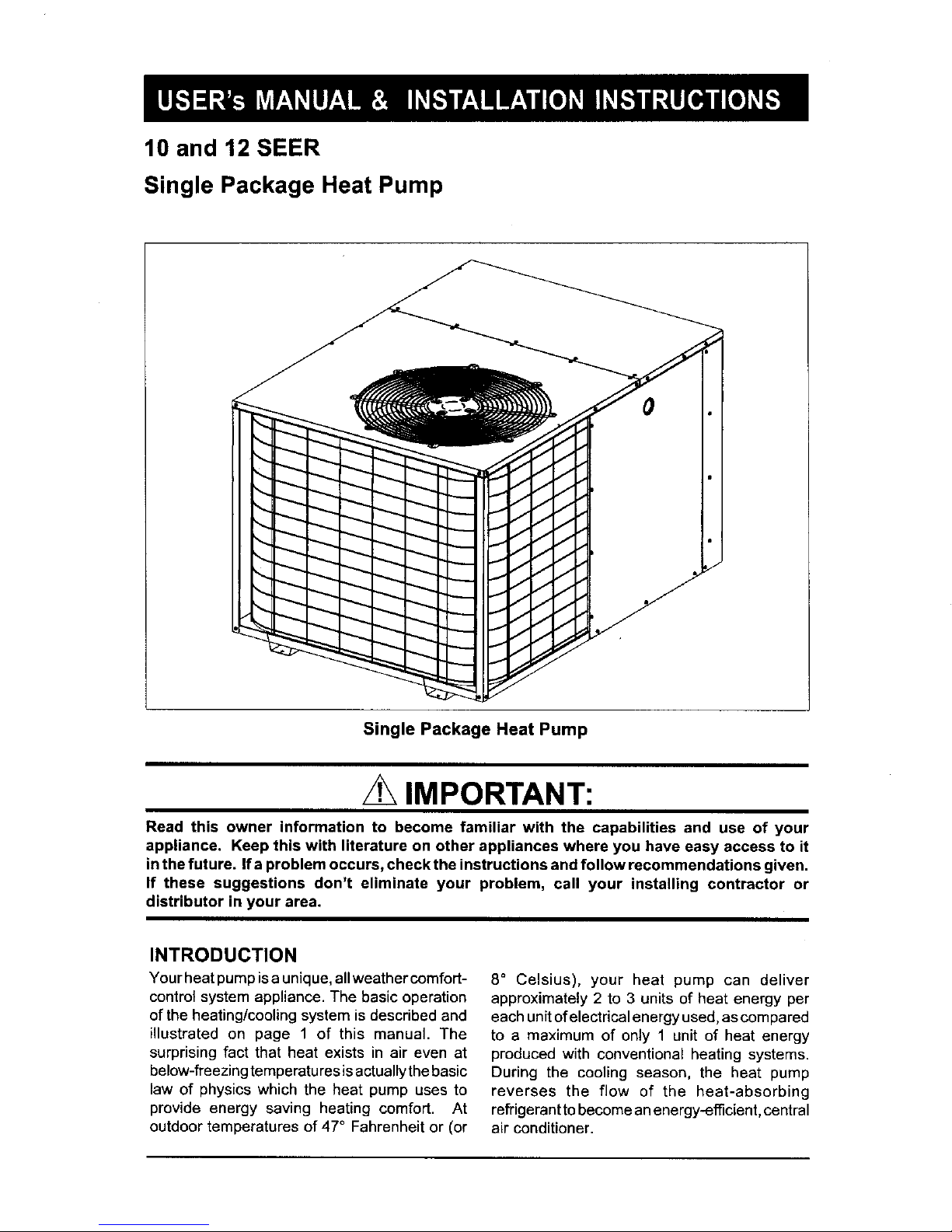
10 and 12 SEER
Single Package Heat Pump
Single Package Heat Pump
IMPORTANT:
Read this owner information to become familiar with the capabilities and use of your
appliance. Keep this with literature on other appliances where you have easy access to it
in the future. If a problem occurs, check the instructions and follow recommendations given.
If these suggestions don't eliminate your problem, call your installing contractor or
distributor in your area.
INTRODUCTION
Your heat pump isaunique, all weather comfort-
control system appliance. The basic operation
of the heating/cooling system is described and
illustrated on page 1 of this manual. The
surprising fact that heat exists in air even at
below-freezing temperatures isactually the basic
law of physics which the heat pump uses to
provide energy saving heating comfort. At
outdoor temperatures of 47° Fahrenheit or (or
8° Celsius), your heat pump can deliver
approximately 2 to 3 units of heat energy per
each unit ofelectrical energy used, as com pared
to a maximum of only 1 unit of heat energy
produced with conventional heating systems.
During the cooling season, the heat pump
reverses the flow of the heat-absorbing
refrigerant to become an energy-efficient, central
air conditioner.

2
SECTION 1. OWNER INFORMATION
Your heat pump will heat and cool your home
year round, saving your energy dollars. During
the summer, a heat pump performs like any
normal air conditioner. That is, the excess heat
energy inside the home is absorbed by the
refrigerant and exhausted outside the home.
During the winter months, a heat pump performs
like an air conditioner run in reverse. That is,
available heat energy outside the home is
absorbed by the refrigerant and exhausted inside
the home. This is an efficient heating means
because you only pay for "moving" the heat from
the outdoors to the indoor area. You do not pay
to generate the heat, as is the case with more
traditional furnace designs.
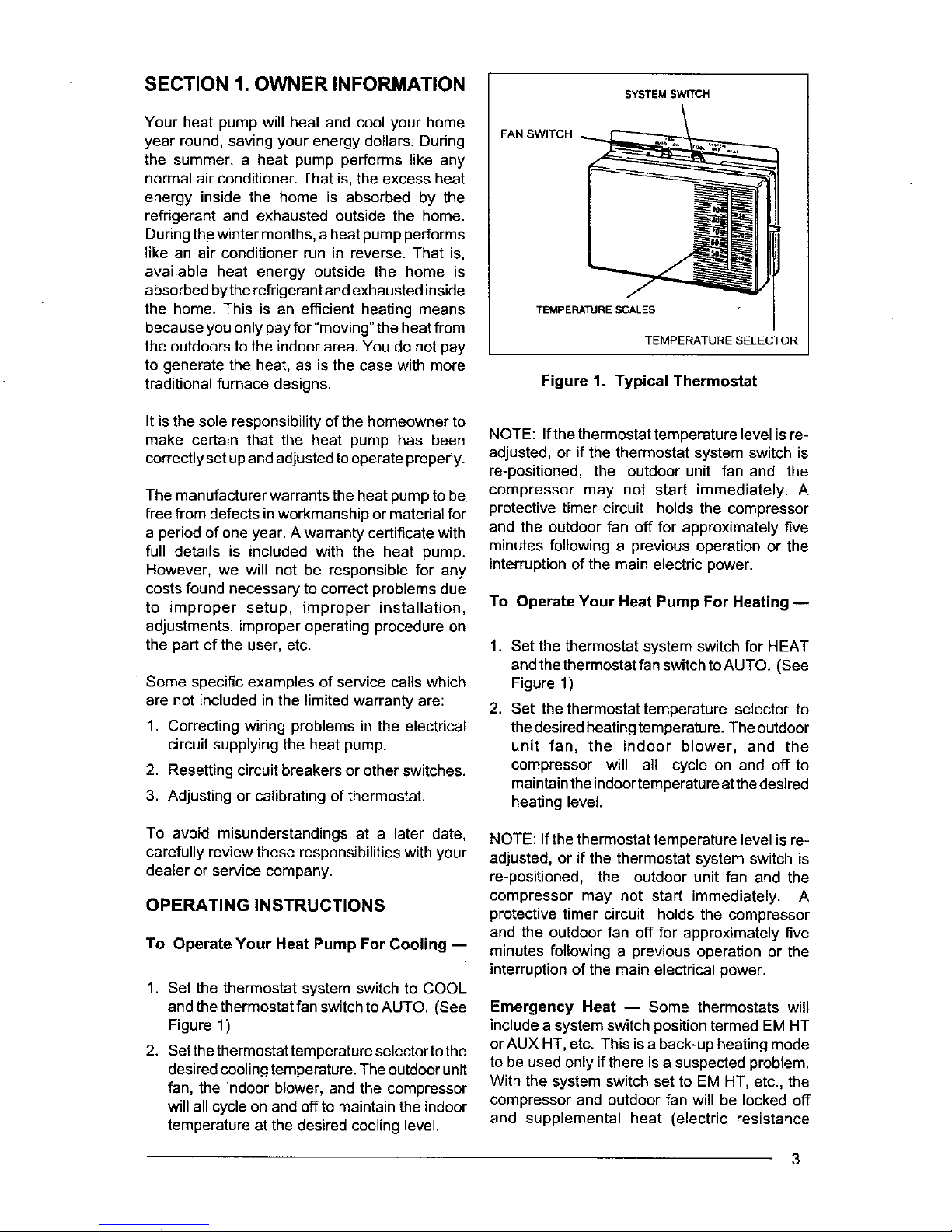
FAN SWITCH
SYSTEM SWITCH
TEMPERATURE SCALES
TEMPERATURE SELECTOR
Figure 1. Typical Thermostat
It is the sole responsibility of the homeowner to
make certain that the heat pump has been
correctly set upand adjusted to operate properly.
The manufacturer warrants the heat pump to be
free from defects in workmanship or material for
a period of one year. A warranty certificate with
full details is included with the heat pump.
However, we will not be responsible for any
costs found necessary to correct problems due
to improper setup, improper installation,
adjustments, improper operating procedure on
the part of the user, etc.
Some specific examples of service calls which
are not included in the limited warranty are:
1. Correcting wiring problems in the electrical
circuit supplying the heat pump.
2. Resetting circuit breakers or other switches.
3. Adjusting or calibrating of thermostat.
To avoid misunderstandings at a later date,
carefully review these responsibilities with your
dealer or service company.
OPERATING INSTRUCTIONS
To Operate Your Heat Pump For Cooling --
1. Set the thermostat system switch to COOL
and the thermostat fan switch to AUTO. (See
Figure 1)
2. Set the thermostat temperature selector tothe
desired cooling temperature. The outdoor unit
fan, the indoor blower, and the compressor
will all cycle on and off to maintain the indoor
temperature at the desired cooling level.
NOTE: Ifthe thermostat temperature level is re-
adjusted, or if the thermostat system switch is
re-positioned, the outdoor unit fan and the
compressor may not start immediately. A
protective timer circuit holds the compressor
and the outdoor fan off for approximately five
minutes following a previous operation or the
interruption of the main electric power.
To Operate Your Heat Pump For Heating --
1. Set the thermostat system switch for HEAT
and thethermostat fan switch toAUTO. (See
Figure 1)
2. Set the thermostat temperature selector to
the desired heating temperature. The outdoor
unit fan, the indoor blower, and the
compressor will all cycle on and off to
maintain the indoor temperature atthe desired
heating level.
NOTE: If the thermostat temperature level is re-
adjusted, or if the thermostat system switch is
re-positioned, the outdoor unit fan and the
compressor may not start immediately. A
protective timer circuit holds the compressor
and the outdoor fan off for approximately five
minutes following a previous operation or the
interruption of the main electrical power.
Emergency Heat -- Some thermostats will
includea system switch position termed EM HT
orAUX HT, etc. This isa back-upheating mode
tobe used only if there is a suspected problem,
With the system switch set to EM HT, etc., the
compressor and outdoor fan will be locked off
and supplemental heat (electric resistance
3
heating)will be usedas a sourceof heat.
Sustaineduseof electricresistanceheatin
placeoftheheatpumpwillresultinanincrease
inelectricutilitycosts.
Defrost -- During cold weather heating
operation, the outdoor unit will develop a coating
of snow and ice on the heat transfer coil. This is
normal and the unit will periodically defrost itself.
During the defrost cycle, the outdoor fan will
stop, while the compressor continues to run and
heat the outdoor coil, causing the snow and ice
to melt. During defrost, there may be some
steam rise from the outdoor unit as the warm coil
causes some melted frost to evaporate.
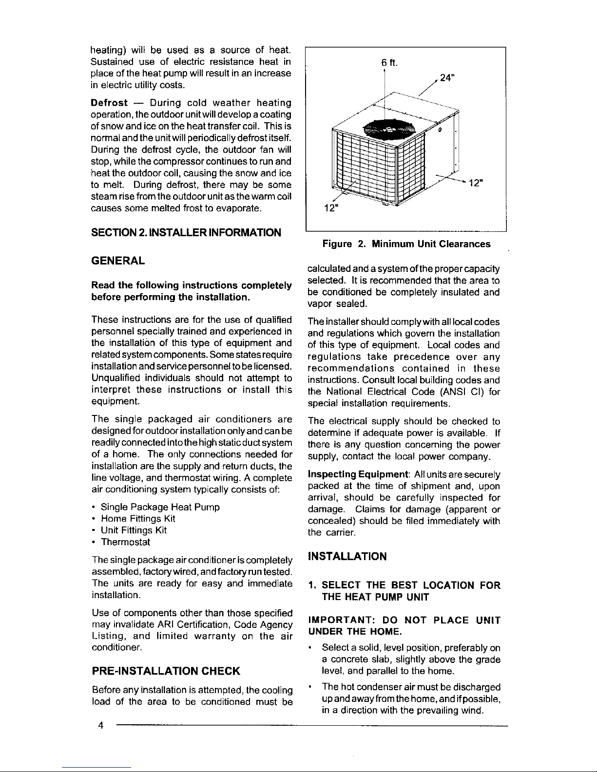
6ft.
24"
12"
12"
SECTION 2. INSTALLER INFORMATION
GENERAL
Read the following instructions completely
before performing the installation.
These instructions are for the use of qualified
personnel specially trained and experienced in
the installati0n of this type of equipment and
related system components. Some states require
installation and service personnel to be licensed.
Unqualified individuals should not attempt to
interpret these instructions or install this
equipment.
The single packaged air conditioners are
designed for outdoor installation only and can be
readily connected into the high static duct system
of a home. The only connections needed for
installationare the supply and return ducts, the
line voltage, and thermostat wiring. A complete
air conditioning system typically consists of:
• Single Package Heat Pump
• Home Fittings Kit
• Unit Fittings Kit
• Thermostat
The single package air conditioner iscompletely
assembled, factory wired, and factory runtested.
The units are ready for easy and immediate
installation.
Use of components other than those specified
may invalidate ARI Certification, Code Agency
Listing, and limited warranty on the air
conditioner.
PRE-INSTALLATION CHECK
Before any installationis attempted, the cooling
load of the area to be conditioned must be
Figure 2. Minimum Unit Clearances
calculated and a system of the proper capacity
selected. It is recommended that the area to
be conditioned be completely insulated and
vapor sealed.
The installer should comply withall local codes
and regulations which govern the installation
of this type of equipment. Local codes and
regulations take precedence over any
recommendations contained in these
instructions. Consult local building codes and
the National Electrical Code (ANSI CI) for
special installation requirements.
The electrical supply should be checked to
determine if adequate power is available. If
there is any question concerning the power
supply, contact the local power company.
Inspecting Equipment: All units are securely
packed at the time of shipment and, upon
arrival, should be carefully inspected for
damage. Claims for damage (apparent or
concealed) should be filed immediately with
the carrier.
INSTALLATION
1. SELECT THE BEST LOCATION FOR
THE HEAT PUMP UNIT
IMPORTANT: DO NOT PLACE UNIT
UNDER THE HOME.
Select a solid, level positionl preferably on
a concrete slab, slightly above the grade
level, and parallel to the home.
The hot condenser air must be discharged
up and away from the home, and if possible,
in a direction with the prevailing wind.
Donotplacetheunitinaconfinedspace.
Ifpractical,placetheheatpumpwhereitand
theductswillbeshadedfromtheafternoon
sunwhentheheatloadisgreatest.
Trytoselectasitefortheunitthatisasclose
as possibleto the proposedreturngrille
location.
Keepinmindthatthelengthofthesupplyand
returnductsshouldbekeptto aminimum
withnosharpradiusedbends.
2. UNPACK THE UNIT
It is recommended that the unit be unpacked at
the installation site to minimize damage due to
handling.
CAUTION:
Do not tip the unit on its side. Oil may
enter the compressor cylinders and
cause starting trouble. If unit has
been set on its side, restore to upright
position and do not run for several
hours. Then run unit for a fewseconds.
Do this three or four times with five
minutes between runs.
The supply and return fittings are included with
select models. If supplied, the duct fittings are
shipped in the supply duct. They attach to the
unit openings with a flange and bead
arrangement, secured with two sheet metal
screws. Note: For ease of access, install fitting
before positioning unit in final location.
SUPPLY DUCT
Position the supply duct collar, if supplied, so the
edge of the unit opening fits between the flange
and the bead. Overlap the collar ends keeping
the small screw holes underneath. Align the
holes in the crimped area and install one screw.
Note: It may be necessary to loosen the four
screws that hold the transition duct in order to
install the supply fitting. Re-tighten when
installation is complete.
Tap collar as necessary to ensure engagement
with unit opening and install second screw.
Tighten first screw. Rotate collar clockwise so
joint is near three o'clock position.
RETURN DUCT
The 12" return duct is installed in the same
mannerasthesupplyduct. Iftheduct hasa 14"
return, follow these instructions.
a. Remove the bands from around the unit.
b. Unfold the top and bottom cap flanges.
c. Carefully remove the top cap and tube.
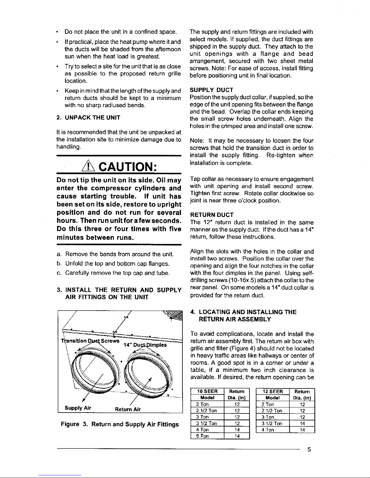
3. INSTALL THE RETURN AND SUPPLY
AIR FITTINGS ON THE UNIT
Align the slots with the holes in the collar and
installtwo screws. Position the collar over the
opening and align the four notches in the collar
with the four dimples in the panel. Using self-
drilling screws (10-16x.5) attach the collar to the
rear panel. On some models a 14" duct collar is
provided for the return duct.
ou'°°':i
SupplyAir ReturnAir
Figure 3. Return and Supply Air Fittings
4. LOCATING AND INSTALLING THE
RETURN AIR ASSEMBLY
To avoid complications, locate and install the
return air assembly first. The return air box with
grille and filter (Figure 4) should not be located
in heavy traffic areas like hallways or center of
rooms. A good spot is in a corner or under a
table, if a minimum two inch clearance is
available. If desired, the return opening can be
10 SEER Return
Model eia. (in)
2 Ton 12
2 1/2 Ton 12
3 Ton 12
3 1/2 Ton 12
4 Ton 14
5 Ton 14
12 SEER Return
Model Oia. (in)
2 Ton 12
2 1/2 Ton 12
3 Ton 12
3 1/2 Ton 14
4 Ton 14
5
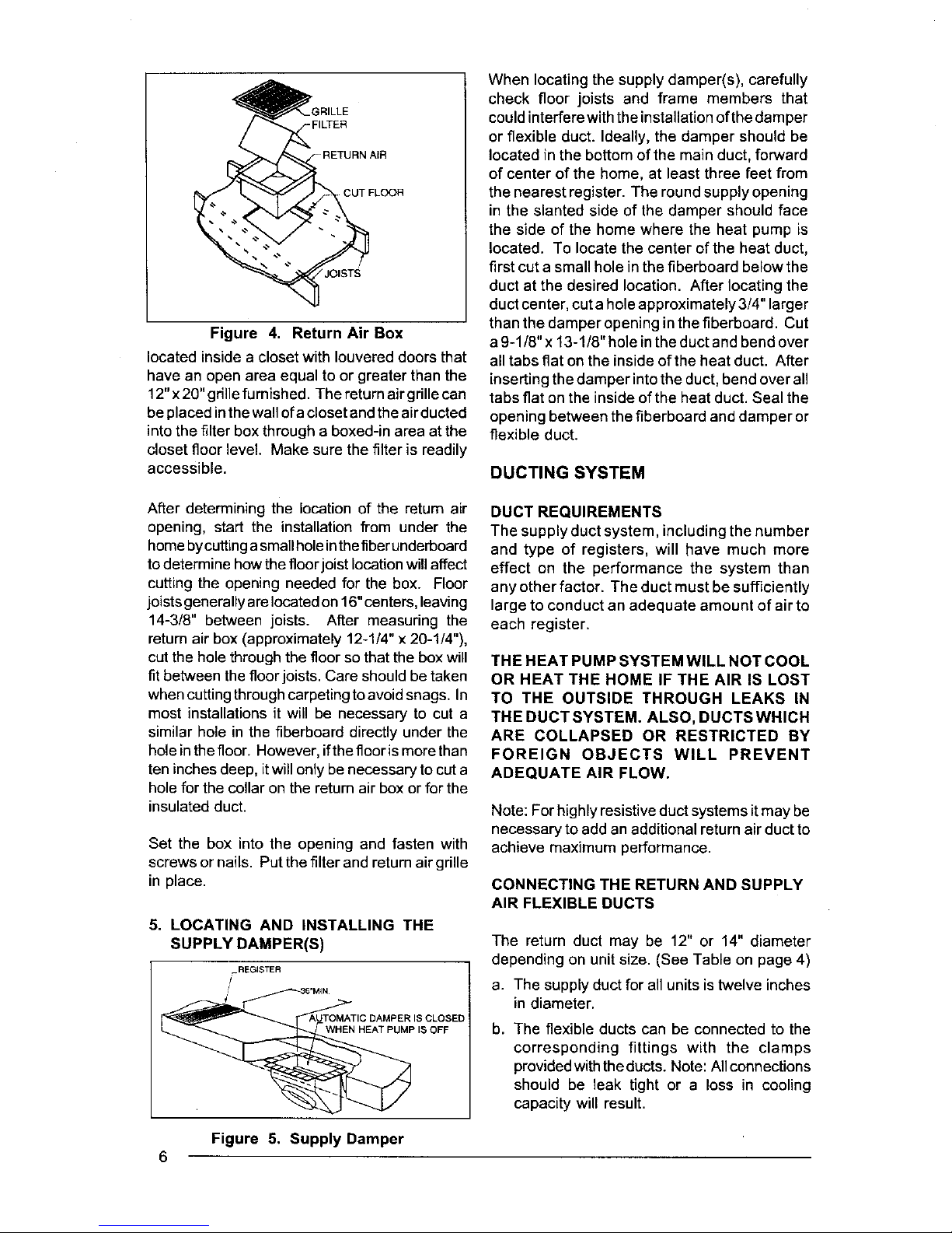
_RILLE
--ILTER
- RETURN AIR
• CUT FLOOR
Figure 4. Return Air Box
located inside a closet with Iouvered doors that
have an open area equal to or greater than the
12"x 20" grille furnished. The return air grille can
be placed in the wall ofa closet and the air ducted
into the filter box through a boxed-in area at the
closet floor level. Make sure the filter is readily
accessible.
When locating the supply damper(s), carefully
check floor joists and frame members that
could interfere with the installation ofthe damper
or flexible duct. Ideally, the damper should be
located in the bottom of the main duct, forward
of center of the home, at least three feet from
the nearest register. The round supply opening
in the slanted side of the damper should face
the side of the home where the heat pump is
located. To locate the center of the heat duct,
first cut a small hole in the fiberboard below the
duct at the desired location. After locating the
duct center, cut a hole approximately 3/4" larger
than the damper opening in the fiberboard. Cut
a 9-1/8" x 13-1/8" hole in the duct and bend over
all tabs flat on the inside of the heat duct. After
inserting the damper into the duct, bend over all
tabs fiat on the inside of the heat duct. Seal the
opening between the fiberboard and damper or
flexible duct.
DUCTING SYSTEM
After determining the location of the return air
opening, start the installation from under the
home by cutting asmall hole inthe fiber underboard
to determine how the floor joist location will affect
cutting the opening needed for the box. Floor
joists generally are located on 16" centers, leaving
14-3/8" between joists. After measuring the
return air box (approximately 12-1/4" x 20-1/4"),
cut the hole through the floor so that the box will
fit between the floor joists. Care should be taken
when cutting through carpeting to avoid snags. In
most installations it will be necessary to cut a
similar hole in the fiberboard directly under the
hole in the floor. However, ifthe floor is more than
ten inches deep, it will only be necessary to cut a
hole for the collar on the return air box or for the
insulated duct.
Set the box into the opening and fasten with
screws or nails. Put the filter and return air grille
in place.
5. LOCATING AND INSTALLING THE
SUPPLY DAMPER(S)
DUCT REQUIREMENTS
The supply duct system, including the number
and type of registers, will have much more
effect on the performance the system than
any other factor. The duct must be sufficiently
large to conduct an adequate amount of air to
each register.
THE HEAT PUMP SYSTEM WILL NOT COOL
OR HEAT THE HOME IF THE AIR IS LOST
TO THE OUTSIDE THROUGH LEAKS IN
THE DUCT SYSTEM. ALSO, DUCTS WHICH
ARE COLLAPSED OR RESTRICTED BY
FOREIGN OBJECTS WILL PREVENT
ADEQUATE AIR FLOW.
Note: For highly resistiveductsystems itmay be
necessary to add an additional return air duct to
achieve maximum performance.
CONNECTING THE RETURN AND SUPPLY
AIR FLEXIBLE DUCTS
The return duct may be 12" or 14" diameter
depending on unit size. (See Table on page 4)
a. The supply duct for all units is twelve inches
in diameter.
b. The flexible ducts can be connected to the
corresponding fittings with the clamps
provided with the ducts. Note: Allconnections
should be leak tight or a loss in cooling
capacity will result.
Figure 5. Supply Damper
6
 Loading...