

Nordyne Q3B, Q3C, Q3A, Q3B A, Q3B C Owner's Manual

USER'S MANUAL AND INSTALLATION
INSTRUCTIONS
Q3B (A,C) Series 10 and 12 SEER
Single Package Heat Pump
Single Package Heat Pump
IMPORTANT
Read this owner information to become familiar with the capabilities and use of
your appliance. Keep this with literature of other appliances where you have easy
access to it in the future. If a problem occurs, check the instructions and follow
recommendations given. If these suggestions don’t eliminate your problem, call
your installing contractor or distributor in your area.
INTRODUCTION
Your heat pump is a unique, all weather comfort-control system appliance. The basic operation of the heating/cooling system is described on page 2 of this manual. The surprising fact that heat exists in air even at belowfreezing temperatures is actually the basic law
of physics which the heat pump uses to
provide energy saving heating comfort. At
outdoor temperatures of 47° Fahrenheit (or 8°
Celsius), your heat pump can deliver approximately 2 to 3 units of heat energy per each unit
of electrical energy used, as compared to a
maximum of only 1 unit of heat energy produced with conventional heating systems.
During the cooling season, the heat pump
reverses the flow of the heat-absorbing refrigerant to become an energy-efficient, central
air conditioner.
SECTION 1. OWNER INFORMATION
To Operate Your Heat Pump For Heating —
Your heat pump will heat and cool your home
year round, saving your energy dollars. During
the summer, a heat pump performs like any
normal air conditioner. That is, the excess heat
energy inside the home is absorbed by the
refrigerant and exhausted outside the home.
During the winter months, a heat pump performs
like an air conditioner running in reverse. That
is, available heat energy outside the home is
absorbed by the refrigerant and exhausted
inside the home. This is an efficient heating
means because you only pay for “moving” the
heat from the outdoors to the indoor area. You
do not pay to generate the heat, as is the case
with more traditional furnace designs.
OPERATING INSTRUCTIONS
To Operate Your Heat Pump in Cooling —
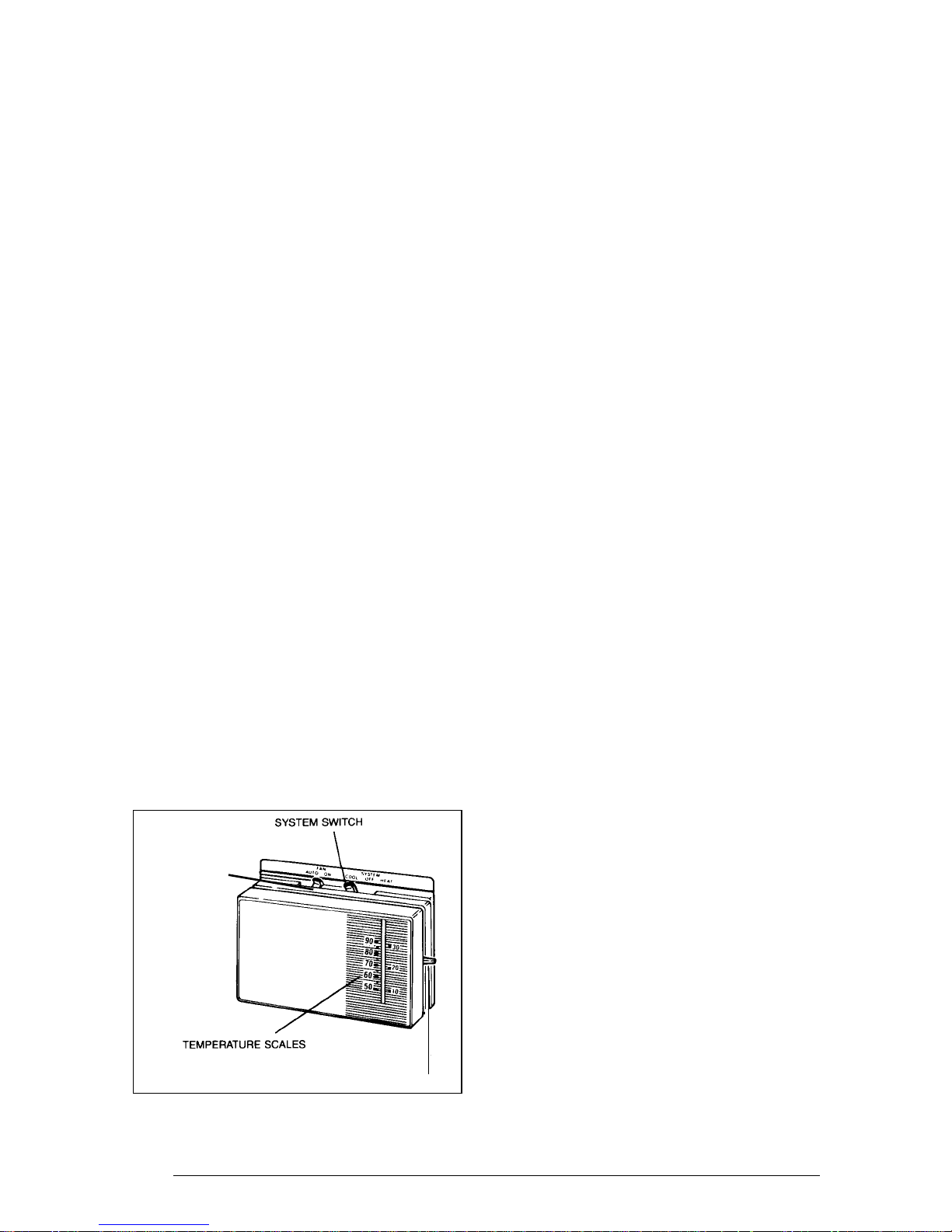
1. Set the thermostat system switch to COOL
and the thermostat fan switch to AUTO.
(See Figure 1)
2. Set the thermostat temperature selector to
the desired cooling temperature. The outdoor
unit fan, the indoor blower, and the compressor
will all cycle on and off to maintain the indoor
temperature at the desired cooling level.
To Shut Off Air Conditioner
1. Turn the system switch to "Heat" or "Off."
2. Turn the thermostat to the desired heating
temperature setting.
FAN SWITCH
1. Set the thermostat system switch to HEAT
and the thermostat fan switch to AUTO.
(See Figure 1)
2. Set the thermostat temperature selector to
the desired heating temperature. The outdoor
unit fan, the indoor blower, and the compressor
will all cycle on and off to maintain the indoor
temperature at the desired heating level.
Defrost — During cold weather heating
operation, the outdoor unit will develop a coating
of snow and ice on the heat transfer coil. This
is normal and the unit will periodically defrost
itself. During the defrost cycle, the outdoor fan
will stop, while the compressor continues to run
and heat the outdoor coil, causing the snow and
ice to melt. During defrost, there may be some
steam rising from the outdoor unit as the warm
coil causes some melted frost to evaporate.
BEFORE YOU CALL A SERVICEMAN
Check your system at the start of each air
conditioning season. Make sure it's working
correctly, clean or change filters and make any
needed adjustments.
In addition, follow these simple rules:
1. Never run your system without a filter. If
you do, the cooling coils will collect dirt and
may become clogged.
2. Leave thermostat set at the comfort level
you wish. Let it control the operation of the
air conditioning system. If room temp is
unsatisfactory, gradually raise the setting
until comfort is restored.
3. It takes longer for an air conditioner to cool
your dwelling than it does for your furnace
to heat it. So . . . don't turn the unit on and
expect an immediate drop in temperature.
If your home is hot and humid, the temperature will drop slowly.
4. Check your filters every 30 days to see if
they are dirty. To keep them clean, use a
mild solution of detergent and water on
washable types. Replace non washable
filters.
5. Keep your outdoor condenser coil clean.
(You can hose it down when it gets dirty.)
TEMPERATURE SELECTOR
Figure 1. Typical Heat/Cool Thermostat
2
If your air conditioner isn't working:
1. Make sure the fuses are not blown or that
your circuit breakers are on.
2. See that your thermostat is set at the
desired temperature and that your system's
switch is on "Cool."
3. For best air flow, make sure your return
grille is not covered and that the filter is
clean.
4. Check the outdoor condenser coil and
make sure it is clean and not clogged with
grass or leaves.
If your air conditioner still isn't working, call your
nearest distributor.
SECTION 2. INSTALLER
INFORMATION
GENERAL
Read the following instructions completely
before performing the installation.
These instructions are for the use of qualified
personnel specially trained and experienced in
the installation of this type of equipment and
related system components. Some states require installation and service personnel to be
licensed. Unqualified individuals should not
attempt to interpret these instructions or install
this equipment.
The single packaged heat pumps are designed
for outdoor installation only and can be readily
connected into the high static duct system of
a home. The only connections needed for
installation are the supply and return ducts, the
line voltage, and thermostat wiring.
The single package heat pump is completely
assembled, factory wired, and factory run tested.
The units are ready for easy and immediate
installation.
this type of equipment. Local codes and regulations take precedence over any recommendations contained in these instructions. Consult
local building codes and the National Electrical
Code (ANSI CI) for special installation requirements.
The electrical supply should be checked to
determine if adequate power is available. If
there is any question concerning the power
supply, contact the local power company.
Inspecting Equipment: All units are securely
packed at the time of shipment and, upon
arrival, should be carefully inspected for damage. Claims for damage (apparent or concealed) should be filed immediately with the
carrier.
INSTALLATION
(For Platinum Series ready homes)
1. LOCATE THE 40 AMP BRANCH CIRCUIT DISCONNECT RECEPTACLE AND
DISCONNECT COVER LOCATED OUTSIDE ON ONE OF THE OUTER WALLS
OF THE HOME.
Locate the unit within the reach of the Power
Cord assembly and branch circuit receptacle.
• Create a solid, level position, preferably on a
concrete slab or plastic pad (use NORDYNE
P/N-903897 or equivalent) and slightly above
grade level, located where the skirting channel across top of unit is directly under bottom
edge of wall. (See Fig. 2)
• Minimum clearances to obstructions. (See
Fig. 2)
Use of components other than those specified
may invalidate ARI Certification, Code Agency
Listing, and limited warranty on the heat pump.
PRE-INSTALLATION CHECK
Before any installation is attempted, the cooling
load of the area to be conditioned must be
calculated and a system of the proper capacity
selected. It is recommended that the area to be
conditioned be completely insulated and vapor
sealed.
The installer should comply with all local codes
and regulations which govern the installation of
6 ft.
24"
Skirting
Channel
36"
Figure 2. Minimum Unit Clearances
12"
12"
3
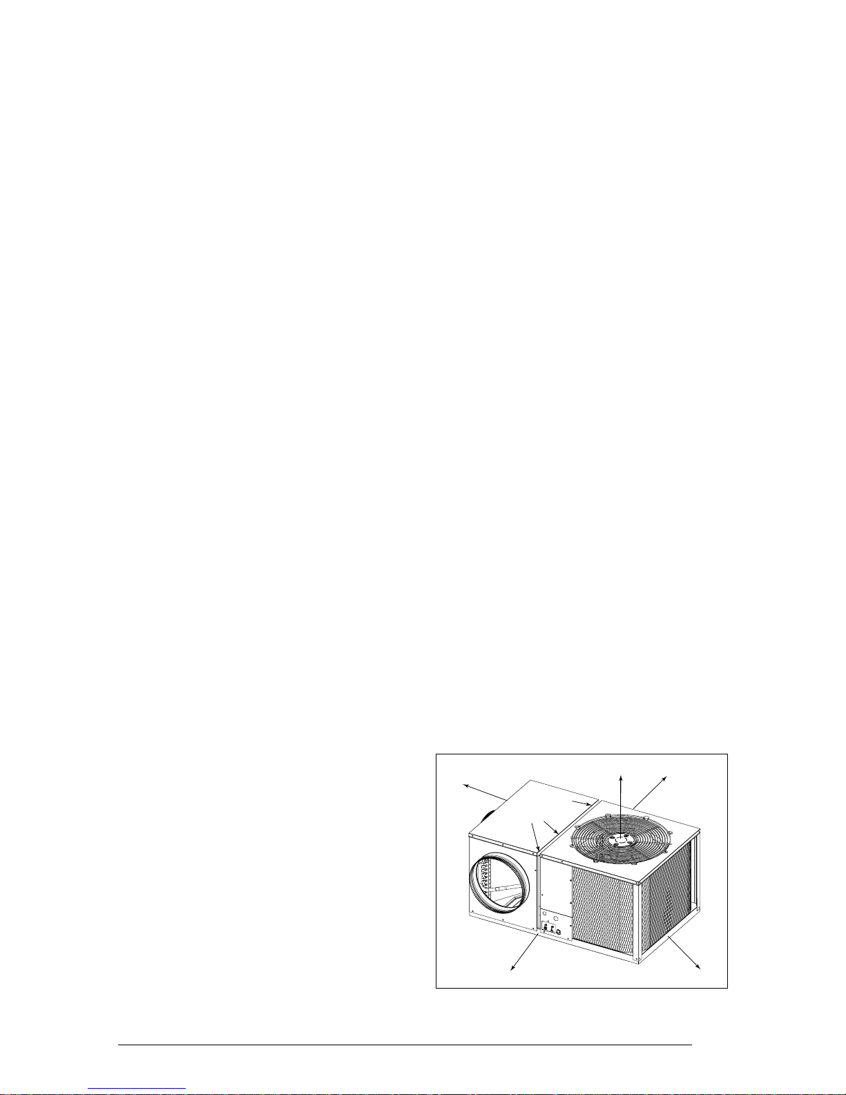
2. UNPACK THE UNIT
It is recommended that the unit be unpacked at
the installation site to minimize damage due to
handling.
a. Remove the bands from around the unit.
b. Unfold the top and bottom cap flanges.
c . Carefully remove the top cap and tube.
!
CAUTION:
Do not tip the unit on its side. Oil may
enter the compressor cylinders and
cause starting trouble. If unit has been
set on its side, restore to upright position and do not run for several hours.
Then run unit for a few seconds. Do
this three or four times with five minutes between runs.
3. INSTALL THE RETURN AND SUPPLY
AIR FITTINGS ON THE UNIT
The supply and return fittings are shipped in the
supply duct. They attach to the unit openings
with a flange and bead arrangement, secured
with two sheet metal screws. Note: For ease of
access, install fitting before positioning unit in
final location.
CONNECTING THE RETURN AND SUPPLY
AIR FLEXIBLE DUCTS
a. Use 12” duct to connect unit to the home
duct system. (See Fig. 3 and 4)
b. Use 14” duct to connect unit to furnace.
(See Fig. 3 and 4)
c. The flexible ducts can be connected to the
corresponding fittings with clamps (field
supplied). Note: All connections should be
leak tight or a loss in cooling capacity will
result.
d. The flexible ducts may be cut to the re-
quired length, see instructions packed with
duct. Keep all ducts as short and straight
as possible. Avoid sharp bends.
e. Ducts may be spliced with sheet metal
sleeves and clamps.
f. Once the inner duct is connected to the
proper fitting, the insulation and plastic
sleeve should be pulled over the connection and clamped.
g. For homes with multiple supply ducts or for
special applications, a Y fitting is available
to divide the supply air so it can be ducted
to different areas of the home for more
efficient cooling/heating. Note: The Y fitting
should be insulated for maximum performance.
CONDENSATE DRAIN
SUPPLY DUCT
Position the supply duct collar so the edge of the
unit openings fit between the flange and the
bead. Overlap the collar ends keeping the small
screw holes underneath. Align the holes in the
crimped area and install one screw.
Tap collar as necessary to ensure engagement
with unit opening and install second screw.
Tighten first screw.
DUCTING SYSTEM
DUCT REQUIREMENTS
THE AIR OUTPUT OF THE SYSTEM WILL
NOT CONDITION THE HOME IF THE AIR IS
LOST TO THE OUTSIDE THROUGH LEAKS
IN THE DUCT SYSTEM. ALSO, DUCTS
WHICH ARE COLLAPSED OR RESTRICTED
BY FOREIGN OBJECTS WILL PREVENT
ADEQUATE AIR FLOW.
A 3/4” condensate drain connection is located
on the side of the unit below the electrical
compartment. (See Figure 5). A field supplied
condensate drain should be installed. Route the
condensate to a suitable drainage area. Any
connecting tube or hose must have the outlet
below the fitting on the unit for proper drainage.
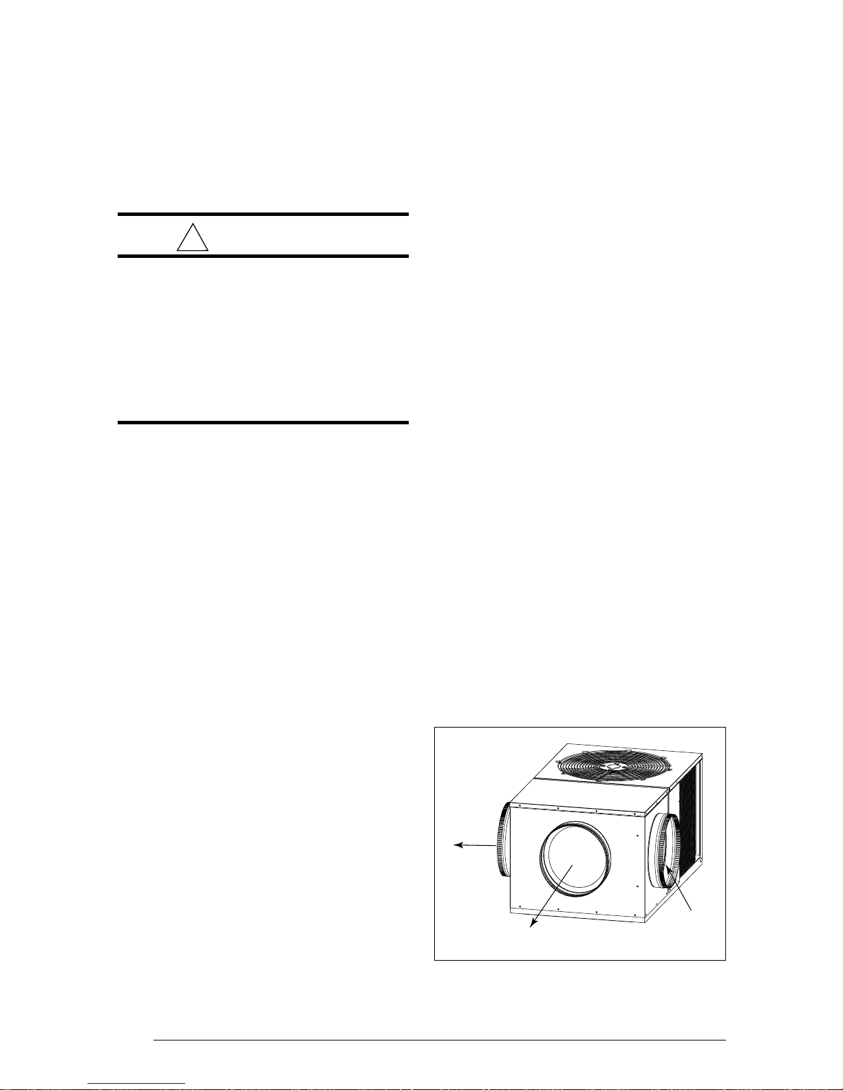
12" Dia.
Supply Air
To Main Ducts (2)
Figure 3. Supply Air Fittings
12"
Dia.
Supply Air
From Furnace
14" Dia.
4
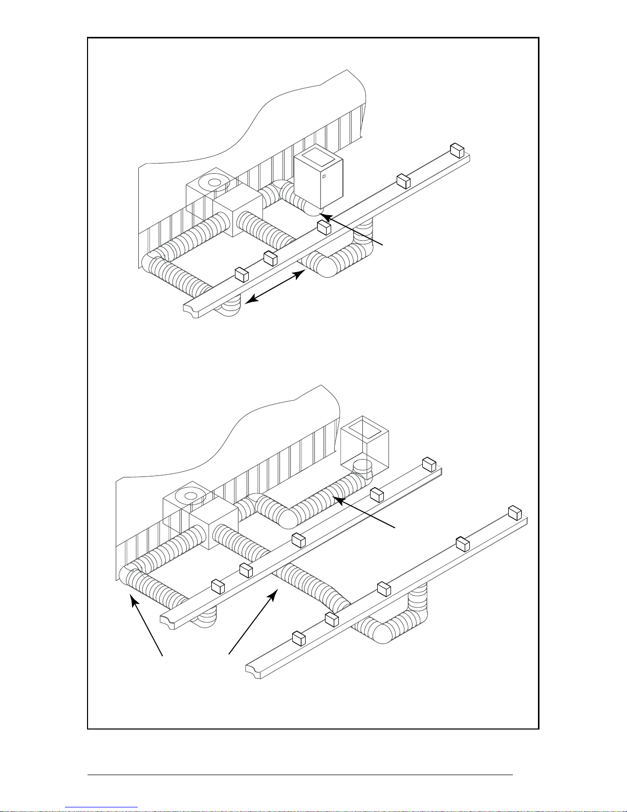
Q3B WITH M1 OR E2 FURNACE INSTALLATION
12" Flex Duct
SINGLE DUCT APPLICATION
14" Flex Duct
12" Flex Duct
14" Flex Duct
MULTIPLE DUCT APPLICATION
Figure 4. Typical Applications
5
!
WARNING:
Turn off electrical power before servicing controls. Severe electrical
shock may result unless power is
turned off. Unit must be installed in
compliance with the National Electrical Code (NEC) and local codes.
Contactor
Lugs
L2 (White)
L1 (Black)
Ground
(Green)
Low
Voltage
Connections
Low
Voltage
Entry
Condensate Drain
Figure 5. Power Entry and Hook Up
High Voltage Entry
ELECTRICAL CONNECTIONS
1. ELECTRICAL SERVICE
HIGH VOLTAGE
a. An approved branch circuit disconnect
receptacle of adequate size and disconnect cover per NEC has already been
installed at the intended location of the unit
on one of the four exterior walls of the home.
b. Attach the approved Power Cord/Discon-
nect Plug (NORDYNE P/N-903899) to the
unit using a strain relief connector (Romex
type or equivalent) through the high voltage
knockout provided.
c . Extend the power cord leads up into the
control panel and connect L1 (Black) and
L2 (White) directly to the contactor lugs
provided. (See Fig. 5)
d. Ground the heat pump unit by attaching the
power cord ground wire (Green-w/ eyelet)
to the unit using the green grounding screw
provided in the control panel. (See Fig. 5)
LOW VOLTAGE
a. Low voltage wiring from the indoor furnace
and thermostat will be located under the
home near the branch circuit receptacle
and cover. Route the 24V control wires
through the low voltage sealing grommet.
(See Figure 5)
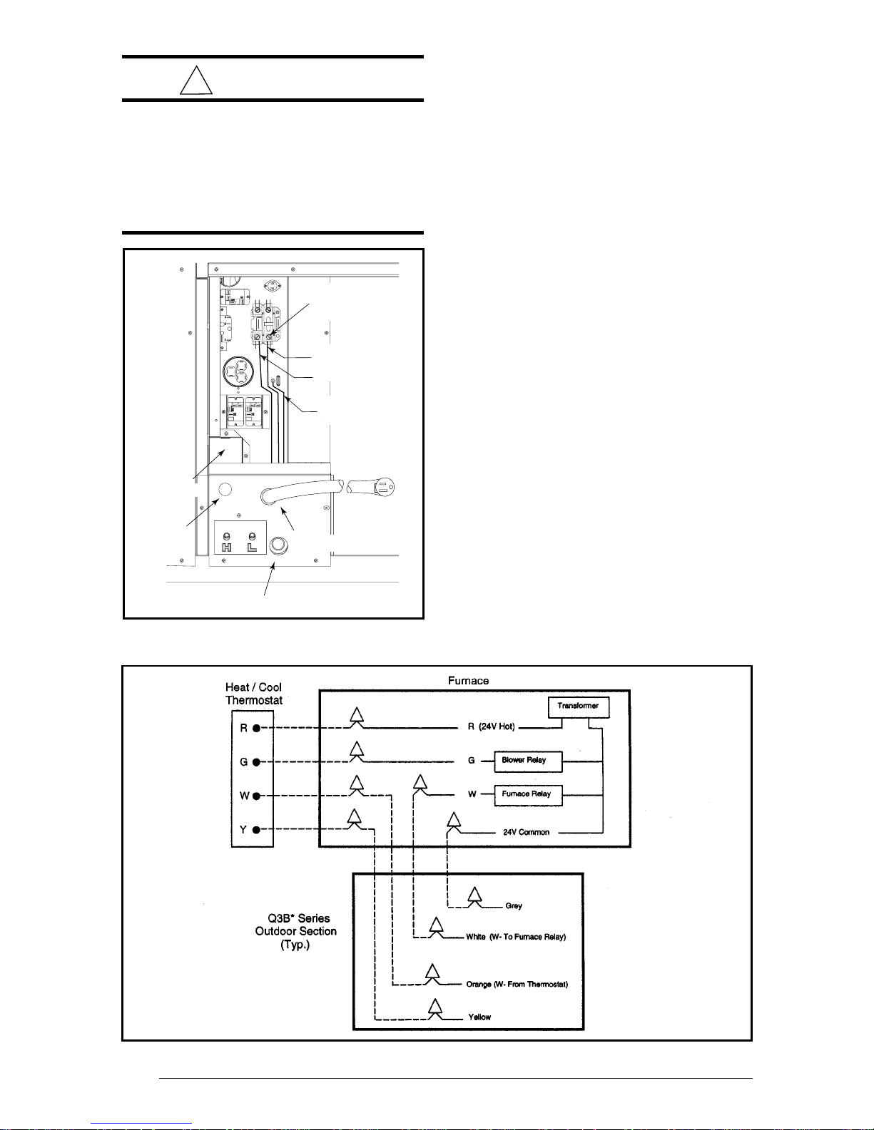
b. Connect the low voltage control wires to the
leads in the low voltage compartment as
shown in Figure 5 and 6.
6
Figure 6. Low Voltage Connections
 Loading...