

Page 1
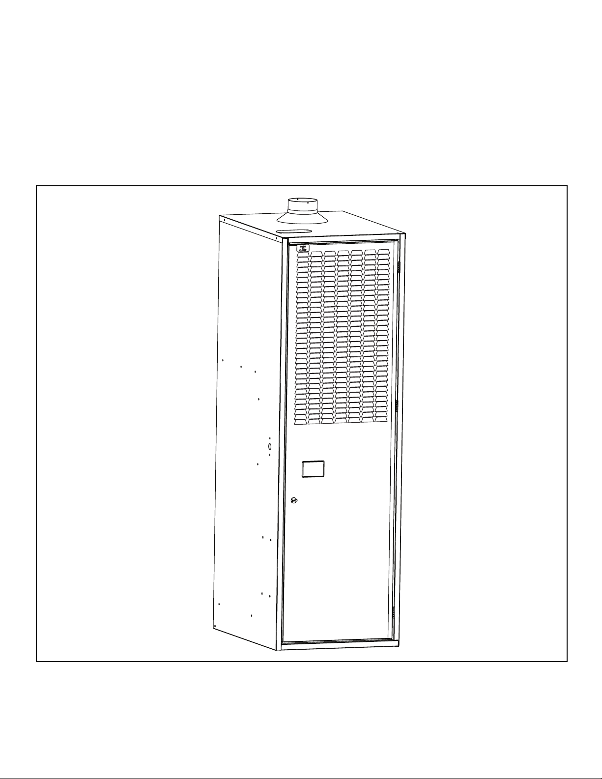
CMF Series
PO and PG Furnaces
Service Manual
Page 2
Index
Page
Introduction .......................................................................................................................... 3
Electrical Supply & Polarity .................................................................................................. 3
Door Switch.......................................................................................................................... 4
Fan/Limit Switches ............................................................................................................... 4
Blower Motor ........................................................................................................................ 4-5
Oil Burner ............................................................................................................................. 5
Oil Pump .............................................................................................................................. 5-6
Natural to LP Conversion ..................................................................................................... 6
Igniter (Power Gas Only)...................................................................................................... 7
Primary Control .................................................................................................................... 7
Cad Cell ............................................................................................................................... 8
Ignition Transformer ............................................................................................................. 8
Electrode Setting.................................................................................................................. 9
Combustion Air Band ........................................................................................................... 9
Air Housing, Blower Wheel................................................................................................... 10
CB200A Base....................................................................................................................... 10
Troubleshooting Flow Charts ............................................................................................... 11-15
Service Guide....................................................................................................................... 16-17
Oil to Gas Conversion .......................................................................................................... 18-22
Wiring Diagrams................................................................................................................... 23-24
!
CAUTION:
This service manual is primarily intended to assist qualified individuals experienced in
servicing heating and air conditioning appliances and is not intended to be used by
unqualified personnel.
Performing service as outlined in this service manual will require the use of calibrated test
instruments. Using uncalibrated test instruments will result in faulty diagnoses. All
instruments should be used in accordance with the manufacturer's instructions.
2
Page 3
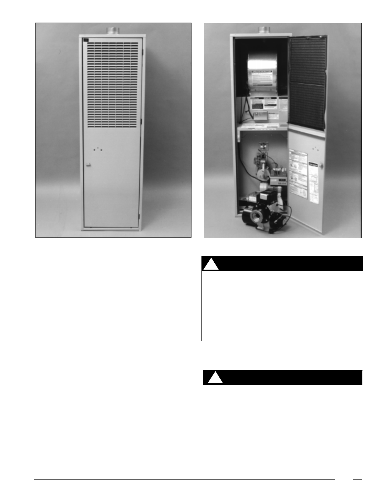
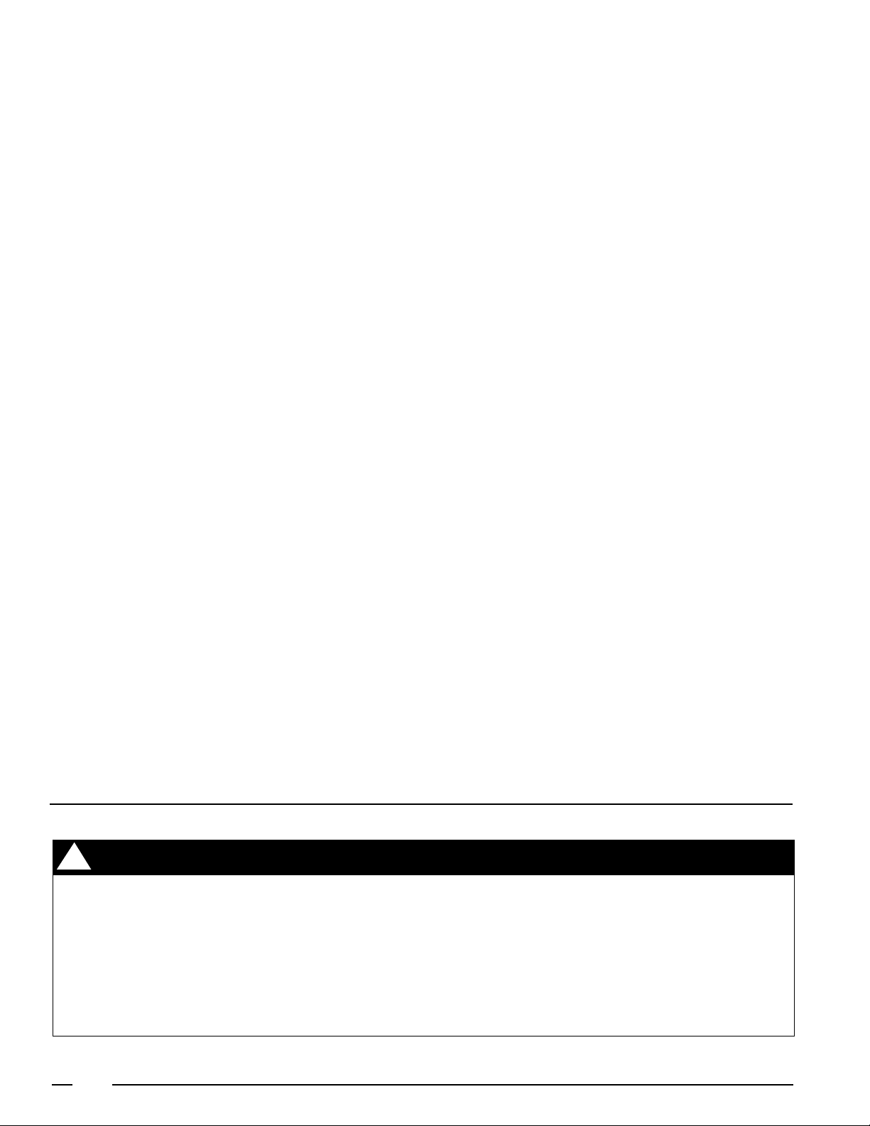
Figure 1
These instructions are intended for use by qualified individuals specially trained and experienced in installation of this
type of equipment and related system components. Installation and service personnel are required by some governing
bodies to be licensed. Persons not qualified should not
attempt to install or service the equipment, nor interpret
these instructions. These furnaces must be installed in
accordance with local codes and ordinances.
These furnaces are high quality, direct vent furnaces that are
convertible from power oil to power gas. The PO models are
Power Oil. The PG models are Power Gas models . Gas
models are designed for operation with natural or LP. gas.
The furnaces are Listed by Underwriters Inc. for use in
manufactured (mobile) homes and recreational vehicles
and as a central furnace, special type when installed with
model CB200A outlet Air base.
Standard Flue Furnaces
The current line of furnaces using the standard flue system
are the CMF series. This is a heating only, sealed combustion furnace, which draws its combustion air from under the
home via a combustion air duct and vents the flue gases
through the standard roof jack. This furnace must be installed with the MA-100 or MA-200 base, the SRJ series roof
jack, and the vent pipe used in conjunction with the SRJ roof
jack to meet U.L. requirements.
Figure 2
W ARNING
!
This furnace must be installed by a qualified
installing agency and in accordance with local
codes and ordinances. Failure to properly install
the furnace, base assembly, and venting system
as described in the Installation Instructions may
damage the equipment and/or the home, can
create a fire or asphyxiation hazard, violates U.S.
Listing requirements, and will void the warranty.
Testing the Electrical Polarity (See Figure 3)
1. See line voltage connections on unit wiring diagram in
the back of this manual.
CAUTION
!
Be careful to avoid electrical shock hazard.
2. With power on at the fuse box, test the line voltage
conductors to the ground with a voltmeter set on the
proper scale.
a. L1 to ground should read 120 Volt AC ±10%.
b. Neutral to ground should read zero volts.
NOTE: Test with power on and conductors disconnected
from furnace connections.
3. If a reading other than above is read, reverse conductors.
3
Page 4
NOTE: If 120 volts AC + 10% is not read, check power
source.
Door Switch (See Figure 3)
The door switch is a safety that will shut off 120 volt power
to the furnace when the furnace door is open. It is a 2 position
switch.
1. Open furnace door.
2. Attach the voltmeter to the door switch. 120 volt + 10%
should be read.
3. Push in on the door switch the reading should go to zero
volts.
Remove Door Switch
1. Shut off power to furnace.
2. Disconnect 2 electric wires.
3. Press in at top and bottom of switch.
4. Remove door switch.
5. To reinstall, reverse steps 1 to 4 above.
Fan and Limit Switch Combination
(See Figure 4)
Testing the Limit Switch (See Figure 5)
When testing the limit switch with a voltmeter, a 120V +/10% reading indicates the switch is open and defective. The
limit switch should be replaced if cooled below switch
setting.
1. Turn off electrical power to the main power source.
2. Disconnect wires from limit switch located inside of
control panel. See wiring diagram, located in control
panel.
Figure 5
3. Using an ohmmeter, connect leads to limit switch
terminals.
4. If limit switch is below temperature, it will read continuity.
If there is not continuity, replace limit switch by removing
two 1/4" screws.
Removing the Limit Switch
1. Turn power off to the unit.
2. Unwire electrical supply.
3. Remove 2, 1/4" screws.
4. To replace, reverse steps 1-3.*
*Limit switch can be either manual or automatic reset.
Manual reset limit will be approved on serial date codes
of 9706 and later.
Testing the Fan Switch
The steps necessary to check the operation of the fan switch
in the air circulation circuit are:
1. Turn off power to unit.
2. Turn voltmeter on and set to scale capable of reading
120V.
3. Place leads from voltmeter on both wires of the fan
switch.
4. Turn on 120 volt power supply to furnace. Voltmeter
should read 120V ±10%.
5. With voltmeter leads still attached set room thermostat
above the room temperature until the burner comes on.
6. Watch the dial on the fan switch as the heat exchanger
heats up, the dial should start to rotate. When the fan
switch reaches the on temperature setting the blower
should come on, and 0 volts should be read indicating
a closed switch.
Figure 3
Removing the Fan Switch
1. Shut off power to unit.
2. Remove cover.
3. Disconnect wires.
4. Remove 3, 1/4" screws.
5. To replace, reverse steps 1-4.
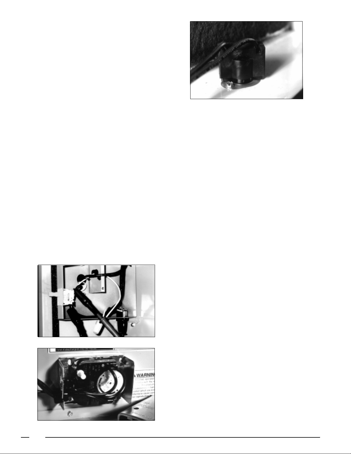
Testing Fan Blower Motor
(See Figure 6)
1. Check for 120 Volts + 10%.
2. Check amperage while unit is running.
3. Visually inspect wheel and motor mounting.
Figure 4
4
Page 5
Removing Blower Motor
1. Turn off power to furnace.
2. Disconnect power wires.
3. Remove two 1/2" screws.
4. Slide blower out.
5. Remove 3, 3/8" screws.
6. Remove blower and blower wheel.
7. Remove blower wheel.
8. To reinstall, reverse steps 1-7.
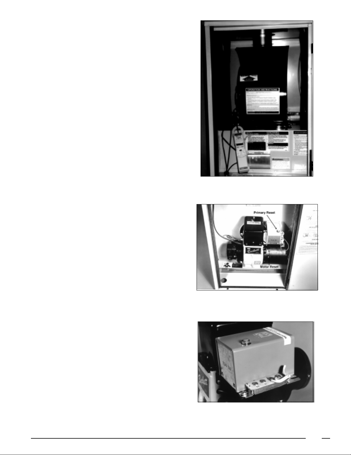
Testing The Oil Burner
(See Figures 6, 7 and 8)
The two manual resets should be checked before testing
any other CMF Furnace Component. These are the Primary
Control and the Burner Motor Manual reset.
Check the incoming power with a voltmeter. Set the voltmeter at the proper scale, a 120V ±10% should be obtained. If
not, check at power cord:
1. Shut off power to the unit.
2. Remove Electric Panel Cover 1, 5/16" screw.
3. Remove 2 wire nuts.
4. Attach voltmeter to incoming power.
5. Turn on power to the unit.
6. Read voltage 120 +/- 10%.
7. Turn off power and reverse steps 1-3.
Figure 6
Test Oil Pump
The fuel(s) used in the oil gun pressure burner applications
are No. 1 Fuel, and No. 2 Fuel . It is recommended to use #1
where temperatures fall below 32°.
The oil storage tank may be installed either above or below
grade. Check local or state codes. To prevent abnormal tank
pressure during fill, the vent pipe should be 1" to 1 1/4" round.
On single line systems, bleed all air out of the fuel supply
system before lighting the furnace.
Test fuel pump resistance or vacuum with a vacuum gauge.
If vacuum reads greater than 10 inches, look for kinked
tubing, a plugged oil filter, undersized line, excessive oil lift,
heavy oil or a frozen line.
Maximum Values for Vacuum Hq.
Single Stage - Single Line
(M units) 6"
Single Stage - Two Line
(M units) 10"
Two Stage
(2 M units) 15"
Figure 7
The second fuel pump test is to check the pump efficiency
or capacity. With the burner running, the efficiency is
satisfactory if the oil pressure can be adjusted to 140 PSI.
After checks, adjust the oil pressure for normal operation
to 100 PSI.
Figure 8
5
Page 6
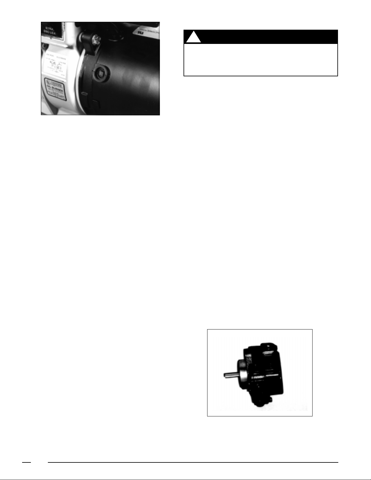
Figure 9
The third fuel pump test is for cut-off. Start the burner and
after a few moments of operation shut off the burner. Upon
shutdown, pressure should drop approximately 15 to 20 PSI.
The two common reasons for inefficient cut-off on fuel
pumps are a defective check valve ball in the pump, or poor
connectors allowing air into the piping system.
Replacing Oil Pump (See Figure 19, page 8)
1. Shut off and disconnect power to the unit.
2. Shut off oil to pump.
3. Remove oil line.
4. Using a 7/16" wrench, loosen oil lines from pump open
to drain assembly.
5. Remove oil lines from pump and move out of the way.
6. Remove 1/4" x 20" x 7/8" hex head screws with 3/8"
open end.
7. Pull pump out slowly.
8. To replace, reverse steps 1-7.
When installing single-line systems, the only connections on
the burner fuel pump is at the intake port. It is important not
to install the “by-pass” plug in the fuel pump return port. A
quick rule which can be used for checking an installation with
the oil storage tank below the fuel pump is to figure:
1. 1" of vacuum for every 10' of horizontal run.
2. 1" of vacuum for every 1' of vertical lift.
3. 1/2" of vacuum for every 90° elbow fitting.
Conversion from Natural Gas to Propane
WARNING
!
Before beginning conversion, shut off electrical power to the furnace at the main power
source. Shut off gas supply.
1. Disconnection
a. Low voltage wires
b. Shut off gas to appliance and remove piping to gas
valve.
2 Remove 3, 3/8" bolts from U-shaped manifold plate and
orifice assembly. (See Figure 4, Page 19 )
3. Replace alternate fuel orifice. Using a 1/2" open end
wrench, remove the main orifice and replace it with the
alternate fuel orifice supplied in the plastic bag with the
burner (located with the home owners packet.)
4. Invert the regulator cap. Warning: check for proper
orifice size listed on furnace rating plate.
5. To reinstall, reverse steps 1-4. Manifold pressure would
then be set to 11.0" W.C. for LP gas.
Changing Complete Burner Assembly
(See Figures 1, page 18 and Figures 2-4, page 19)
1. Open furnace door.
2. Using a 7/16" open end wrench, remove three burner
nuts. Remove burner assembly from furnace.
3. To replace burner, reverse steps 1 & 2.
NOTE: Be certain to install new gasket.
Remove Burner and/or Ignitor
1. Shut off gas supply
2. Remove gas lines from Gas valve.
3. Unplug ignitor.
4. Remove 3, 1/4" screws. Lift burner up and out.
5. Remove 1, 1/4" screw and replace ignitor.
6. Set gap distance between ignitor and burner head at
1/2" - 5/8." Micro amp signal should be between 2 to
4 micro amps (µa).
The single-stage design is used in applications requiring 10"
of vacuum or less. Two-stage pumps are specified when up
to 15" of vacuum is required. If an oil fuel pump is not properly
sized to the vacuum requirements the following will occur:
1. A solid column of oil will not be delivered to the atomizing
nozzle.
2. The light portions of the oil will separate from the heavy
portion.
3. A milky appearance will be seen in the returned oil.
6
Figure 10
Page 7
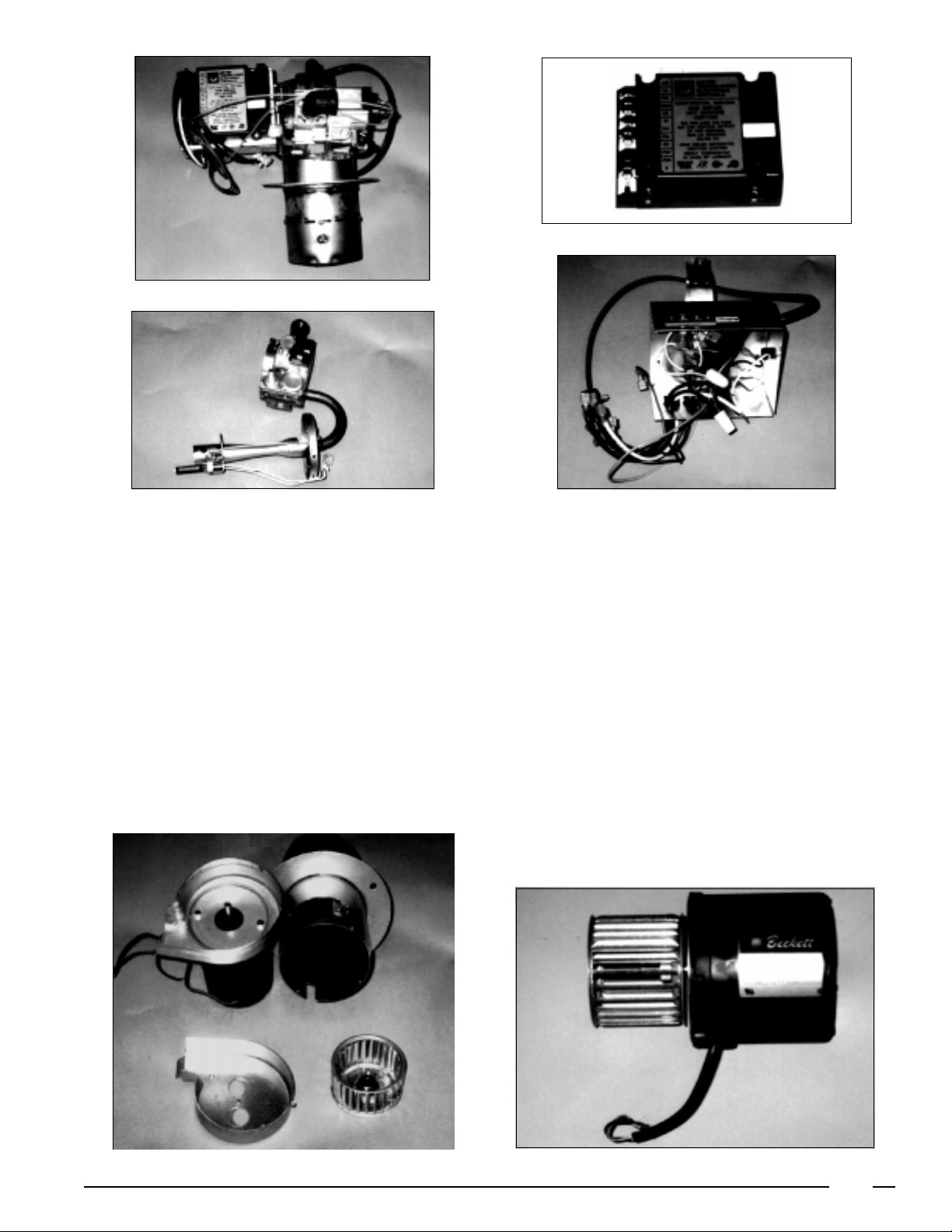
Figure 11
Figure 13
Figure 12
Remove Hot Surface Ignition Series
(See Figure 12)
1. Shut off power to the furnace.
2. Remove all wires 24 volt and 120 volt.
3. Remove 2, 1/4" screws.
4. To remount, reverse steps 1-3.
Removing C Burner Motor (See Figure 4, page 19)
1. Shut off power to the furnace.
2. Remove wires from HSI control.
3. Remove 4, 1/4" screws and HSI control.
4. Remove 2, 1/4" screws and panel cover.
5. Disconnect wires to motor; 2 red and 2 black.
6. Remove 1, 5/8" screw from housing strap and lift off
motor.
7. To reinstall, reverse steps 1-6.
Figure 14
Removal of Air Housing, Blower Wheel and Motor (See
Figures 14 - 16)
1. Shut off power to unit.
2. Remove elect wires.
3. Remove 4, 1/4" screws (2 on each side of air housing).
4. Remove band screw, 5/16" bolt.
5. To replace, reverse steps 1-4.
The 3 circuits of the primary control (see Figure 14) are the
Starting Circuit, Safety Circuit, and the Running Circuit.
Testing the Primary Control Circuits
1. Shut off power to the unit. Close off oil supply.
2. Remove thermostat wires from T1 and T2 and cad cell
wires from F1 and F2.
3. Turn on power to the unit.
4. Jumper out terminals T1 and T2 to test the starting
circuit. The burner should come on and then shut down
after 45 seconds as the safety circuit engages.
Figure 15
Figure 16
7
Page 8
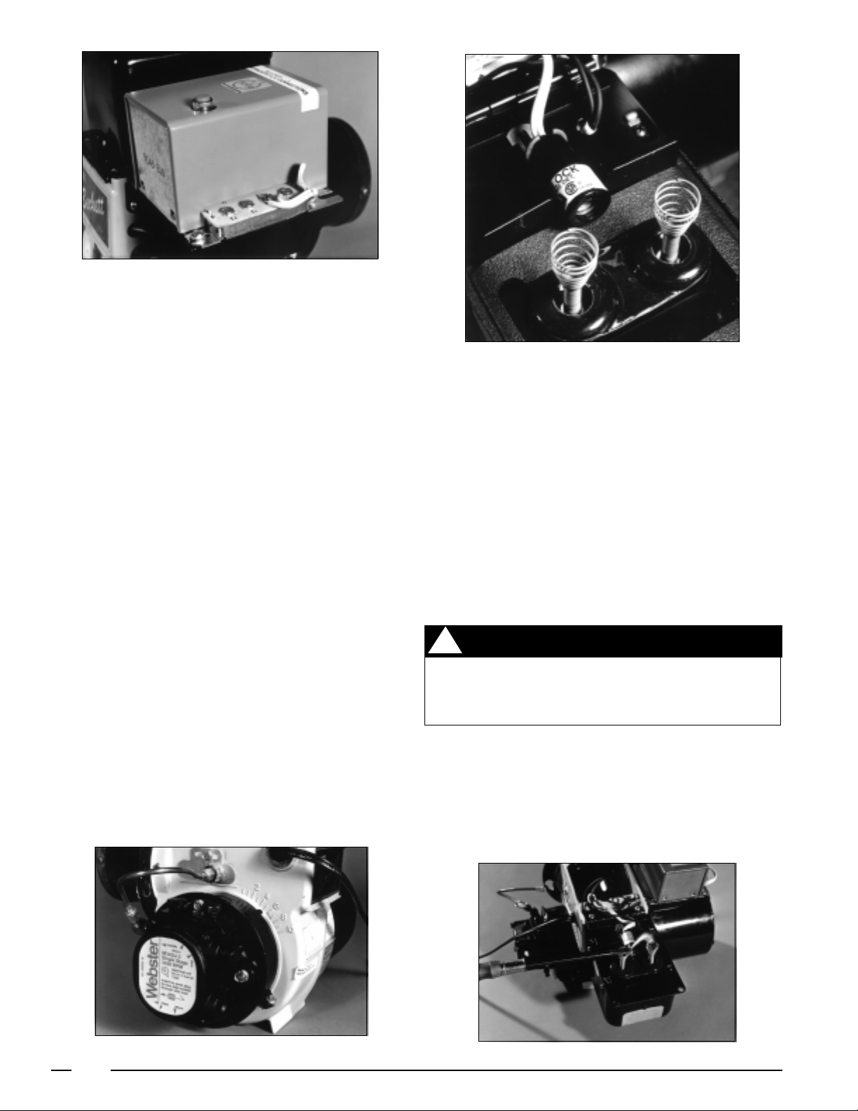
Figure 17
5. Remove jumper wires and allow two minutes for the
safety heater to cool off.
6. Test running circuit by jumpering out T1 and T2 and
reset the primary control. The burner will come on.
7. Immediately jumper F1 and F2 to bypass the cad cell.
The burner should run continuously after 45 seconds
with the cad cell safety circuit by-passed.
8. Shut off power to the unit, remove all jumpers, and then
reconnect the thermostat and cad cell.
9. If any one of these test fails, replace the primary control.
Figure 18
dark condition should give a reading of 100,000 ohms or
infinity. If the reading is lower, let the refractory cool down or
look for stray light that might be entering the burner through
the air inlet, or around the transformer base plate. If the cad
cell is not performing within these guidelines, replace it.
Removing the Primary Control
1. Shut off power to the unit.
2. Open ignition transformer by removing 2 5/16" screws.
3. Remove the black, white and orange wires leading from
the primary control.
4. Remove cad cell wires from F1 and F2, and remove
thermostat wires from T1 and T2.
5. Loosen 2, 1/4" screws and remove primary control.
6. To replace, reverse steps 1-5.
Testing Cad Cell
The cad cell is a light sensing resistor. Its function is to cut
power to the burner motor in the event the electrodes fail to
establish flame.
To check the CAD cell start the burner and unhook both cad
cell leads from the FF terminals on the primary control. After
the burner lights jump the FF terminals to keep the burner
running. Measure the ohms resistance across the cad cell
lead as it views the flame. This should be 1,600 ohms or less.
A preferred reading is 300-1000 ohms. Next, with the meter
still connected to the cad cell leads, turn the burner OFF. The
Removing the Cad Cell
(See Figures 17 and 18)
1. Shut off power to the unit.
2. Remove wires from primary control.
3. Open ignition transformer.
4. Turn cad cell 1/2 turn in retainer and lift out.
5. To replace, reverse steps 1-4.
Testing Ignition Transformer (See Figure 20)
!
WARNING
In testing the ignition transformer extreme
caution should be exercised because 10,000 to
14,000 volts are present.
The most common field test of the ignition transformation
spark is using a service test cord connected to the primary
winding wiring and an INSULATED screw driver. The tests
should indicate an arc:
1. 1/2" long ARC from the terminal post to the casing.
Figure 19
8
Figure 20
Page 9

Figure 21 Figure 22
2. 1/2" long ARC from the alternate terminal post to the
casing. The first test of the ignition transformer is to
check for continuity using an ohmmeter. An infinity
reading indicates a defective transformer. A 10,000 volt
voltmeter is recommended to test the ignition transformer
spark.
3. 1" long ARC from terminal to terminal.
Removing the Ignitor Transformer
1. Shut off power to the unit.
2. Remove white and black wires coming from transformer.
3. Loosen 2, 5/16' screws and turn on tie-down plates.
4. Fold back transformer and remove 2 Phillips head
screws and transformer.
5. To replace, reverse steps 1-4.
Electrode Setting (See Figure 21)
The electrode setting is carefully checked at the factory.
When servicing the burner electrodes, three procedures
should be performed:
1. Set the spacing.
2. Set the gap.
3. Remove the carbon accumulation.
4. Refer to Installation Instructions.
Removing Drawer Assembly
1. Shut off and disconnect power to unit.
2. Remove copper oil line from drawer assembly and
loosen at pump using a 7/16" open end wrench and
move out of way.
3. Mark position of lock plate.
4. Loosen 5/16" screw on lock plate.
5. Remove drawer assembly and set the spacing, gap and
remove any carbon accumulation.
6. To replace, reverse steps 1-5.
The three functions of the atomizing nozzle are atomization,
creating the oil spray pattern and metering the fuel . (See
Figure 22.)
Several precautions should be observed when installing an
oil nozzle. (See Figure 22).
1. Do not clean a dirty nozzle, replace it.
2. Do not bump nozzle with a wrench.
3. Do not touch nozzle with your fingers.
4. Install nozzle with a nozzle wrench.
5. Be sure strainer is in place and tight.
6. Do not over-tighten nozzle during installation.
Low Burner Pressure and Poor Combustion
A flex coupler can contribute to low burner pressure and poor
combustion if the following occurs:
1. The coupler is too long and causes a high amperage
burner motor reading.
2. The coupler is worn and slipping.
3. The fuel pump shaft is worn and rounded causing the
coupler to slip. (See Figure 23)
The proper mixture of fuel and air is delivered to the burner
through an air adjustment band located on the burner
housing. (See Figure 24)
The primary purpose of the combustion chamber liner is to
isolate the combustion process from the rest of the furnace
and prevent damage to the components and the cabinet.
Removing Combustion Air Adjustment Band
1. Remove oil pump. (See oil pump replacement.)
2. Remove 2 5/16" screws from air band.
3. Loosen 1 5/6" screw and remove band housing.
4. To replace, reverse steps 1-3.
Figure 24Figure 23
9
Page 10

Removing Motor and Blower Wheel
1. Shut off power to the unit.
2. Open transformer.
3. Remove motor wire.
4. Remove 2, 3/8" screws.
5. Remove motor and blower wheel.
6. Loosen 1/8" Allen screw and remove wheel. The wheel
will be down 3/4" on the shaft.
7. To replace, reverse steps 1-6. (See Figure 9, page 6
and Figure 16, page 7)
Installation Instructions CB-200A Base
The model CB-200A (901696) base allows for a non-sealed
combustion, central heating (without warm air ducts) installation of the CMF Series furnaces. This installation must be
done by a qualified installing agency in accordance with
local codes and ordinances.
Location
Allow clearance from adjacent materials as stated under
“Minimum Clearances.” Ample clearance should be provided to permit easy access for removal of filters, blower,
motors, controls and vent connections. Unit must be
installed in a level position on NORDYNE base model
CB-200A.
Minimum Clearances To Adjacent Materials
The furnace may be installed in a corner, or against an open
wall with the clearances not less than: Front 36 inches; Top
17 inches; Vent 9* inches for oil units, 6 inches for gas units;
3* inches for rear; and 2** inches for one side if in corner.
* Rear clearance may be 0 inches but vent clearance will be
reduced to 6 inches. Refer to table 8, appendix B of NFBA
No. 31 for requirements to achieve 6 inches vent clearance.
** The minimum clearance from warm air register in base
must be 36 inches. Use a 15 5/8" L x 7" W sheet metal blank
off panel to replace register when clearance is less than 36
inches.
Venting (CB-200A Base)
Unit must be vented through a permanent chimney or 4"
type L, low temperature venting system (oil units) or 4" type
BW venting system (gas units) selected and installed by the
installer. Check chimney for soot, leaks, obstructions and
proper height. If it is necessary to construct a new chimney,
local conditions such as necessary height, draft, and number of appliances served should be checked with local
building codes.
Barometric regulator (oil units)* is to be installed at the vent
connection of the furnace. All flue pipe joints should be
fastened with sheet metal screws for rigidity.
To prevent down-draft, the chimney should extend at least
2' above the peak of roof. The internal area of the chimney
should equal the area of the flue outlet on the furnace. The
chimney should have no obstructions or sharp bends where
soot and other foreign matter can accumulate. If inspection
shows it to be obstructed, the chimney should be cleaned.
The existing flue pipe should be cleaned or a new pipe
should be installed. Connect the flue pipe to the chimney with
few elbows as possible. Do not install hand dampers of any
type.
It is desirable that the furnace flue serves no other appliances. However, when two or more appliances must vent
into a common flue, the area of the common flue should at
least equal the area of the largest flue connector, plus 50%
of the area of the additional flue and vent connectors. The
flue or vent connector must be inserted into, but not beyond,
the inside wall of the chimney flue liner.
Provisions must be made for adequate ventilation to properly support combustion and to maintain safe ambient temperatures.
When buildings are so tight that normal infiltration does not
meet air requirements, one or more permanent openings
must be provided to supply outside air. The minimum cross
section of the duct is to be 1 sq. inch area-free for each 2000
Btuh input for horizontal duct installations, or 4000 Btuh input
for vertical installations. Refer to gas code book.
Installation
Base: The base must be located on a hard surface. When
the furnace location is carpeted, use a hard surface platform
under the base.
Furnace: Set the furnace on the base without damaging the
foam gasket material on the base top. Making sure the
furnace is seated on the back of the base, fasten the front of
the furnace to the base with 1/2" long sheet metal screws.
NOTE: Front register is not adjustable and remains fully
open.
Fuel line piping, wiring, and thermostat: Refer to the installation and operation manuals provided with the furnace.
Horizontal distances to an existing chimney should be as
short as possible and the connecting pipe should slope
upward to the chimney at not less than a 45° angle. Total
length of the sloping pipe must not exceed 6 feet.
10
DANGER: When using CB-200 A (Cottage Base), do not
install the furnace in a mobile home. Do not install the
furnace in a closet, alcove or other enclosed area.
Violation of the above may cause incomplete combustion which may produce poisonous gases causing asphyxiation and resulting in sickness or death.
Page 11

Conduct
Draft Test
Testing Combustion Efficiency
With Bacharach Test Kit
Drill 1/4" Hole on Flue
Turn T’Stat to Highest Thermostat Setting.
Allow 5 Minutes of Operation.
#1
#2
Conduct Flue Gas
Temperature Test
#3 #4 #5
Conduct
CO2 Test
Conduct
Smoke Test
Conduct
Over-Fire
Draft Test
#6
Calculate
Combustion
Efficiency
#7
Plug 1/4"
Hole in Flue
11
Adjust Draft Gauge
to Zero.
Test at Hole in Flue
Dirty
Heat
Exchanger
Less Than
-.025" WC
Over
-.035 WC
Defective
or Blocked
Chimney
Leak in
Smoke
Pipe
Air Band
Adjustment
Soot in
Heat
Exchanger
Too Short
or
Wrong Flue
Test at Hole in Flue.
Allow Thermostat
Needle
to Stabilize
Calculate
Net Stack
Temperature
Over 630˚F
Under
380˚F
Dirty
Heat
Exchanger
Overfiring
Furnace
Baffles
Burnt Out in
Heat
Exchanger
Poor
Combustion
Chamber
Excessive
Draft
Underfiring
Furnace
Test at Hole in Flue. Adjust
Air Band for Highest CO2
Reading (With 0 to 1 Trace
Smoke Reading) Within 10 1/2%
to 11%. Operate Unit 15 Minutes
Before Final Adjustments
Tighten Air
Band Screws
With
Low
Smoke
Under
10 1/2 %
With
High
Smoke
Air Band
Closed
Too Much
Dirty Fan
or Air
Over 11%
Handling
Parts
Too Little
Draft
Burner
Overfiring
Under Firing
Combustion
Chamber
Nozzle
Too Small
Air Leaks
in Furnace
Air Band
Open Too
Wide
Faulty
Nozzle
Operation
Poor
Combustion
Chamber
Air Band
Adjustment
Take Sample
At Hole in Flue
And Compare
To Smoke Sale
Over 2
Spots
Less Than
1 Spot
CO2 High,
Over 11%
CO2 Low,
Under
10 1/2%
No Smoke
on Disc
Oil on
Smoke
Disc
Overfiring
of Unit
Oil Rate
Too High
Too Little
Excess Air
Dirty Fan
or Air
Handling
Parts
Faulty
Nozzle
Operation
Faulty
Combustion
Chamber
Air Leaks
in Furnace
Air Shutter
Open
Too Wide
Excessive
Draft
Excess Air
Set Too High
Poor Nozzle
Operation
Test At
Inspection Door
Above Burner
Pressure Drop
of +.005" to
+.015" WC
Over Fire Draft
of -.01" to
-.03" WC
Good
Less
-.01"WC
Over Fire
Draft
Over
-.03 WC
Over Fire
Draft
Efficiency Finder to
Correct Net Stack
Set Green Arrow
Combustion
and Stack Loss
Stack Draft
+.02" to
+.04" WC
Stack Draft
Over
.05" WC
Defective or
Improperly
Installed Flue
Set Horizontal
Scale on
Temperature
On Vertical
Scale
to % CO2
Read
Efficiency
Defective or
Blocked
Chimney
Leak in
Smoke Pipe
Soot in Heat
Exchanger
Too Short
Draft Stack
Page 12

Oil Burner Operation Complaints
Noisy Fire
Noise or
Pulsation on
Stop/Start
Improperly
Located
Electrodes
Nozzle Installed
Too Far
Forward
Oil-Center
Fire
Too Low
Oil Pressure
Leaky
Nozzle
Install Delayed
Opening
Solenoid on
Nozzle Line
Air in
Fuel Line
Wrong
Nozzle
Replace with
Proper Nozzle
Replace Solid
Cone Design
with Hollow or
Semi-Solid
Design
Smoky Fire
Too Low
Oil Pressure
Improper
Flue
Air
Restriction
Fan Blades
Air Intake
Air Vanes
Damaged
Combustion
Chamber or
Burner Tube
and Choke
Nozzle
Restriction
Supply Line Filter
Delayed
Ignition
Improper
Electrode
Setting
Short
Circuit
Cracked Insulator
Layer of Soot or Oil
Air Shutter
Opening Too
Wide
(Some Models)
Clogged
Nozzle
Replace Hollow
Cone Design
with Solid
Cone Nozzle
Improper Drawer
Assembly
Adjustment
Long Fire
Spray Angle
Mismatched
Head Assembled
Oil Pressure
Too Small
Too Large
Nozzle
Capacity
Spray &
Atomizing
Pattern
Combustion
or Located
Improperly
Too Low
Furnace Room
Odors
Improper
Over Fire
Draft
Flue
Obstruction
Improper
Chimney Draft
Design
Unit
Overfiring
Excessive Air
Through Burner
Delayed
Ignition
Too Low
Oil Pressure
Defective
Nozzle
Oil Viscosity
Too High -
Increase Pump
Pressure to
120-125 PSI,
Use Next Smallest
Size Nozzle
Tank Sediment
Air
Adjustment
Carbon Build-up
on Combustion
Chamber Walls
Replace Hollow
Cone Design with
Solid Cone Nozzle
Return Air
Restriction
Negative
Pressure
Around
Furnace?
Return Air
Shortage
12
Page 13

Oil Burner Operation Complaints
Oil Drips from
Nozzle
On Shut Down
Air in Oil
Pressure Pipe
Between Pump
and Nozzle
Defective
Pump Cut-off
During Operation
Nozzle Too
Far Behind
Combustion
Head
Ignition
Electrodes
Protrude Into
Oil Spray
Loose Fitting
Nozzle
Contaminated
Nozzle
Too Low Oil
Pressure
Cracked Nozzle
Line or Adapter
Improper
Flue Gas
Temperature
Too High
Excess Air
Deposits
Oil Pressure
Too Large
Oil Nozzle
Too Low
Too Small
Oil Pressure
Cold Air Entry
Into Flue Pipe,
Soot
Too High
Nozzle
Too Low
Test CO2%
Oil and Coke
Collect Around
Nozzle and
Combustion Head
Defective
Nozzle
Too Large or
Incorrect
Spray Pattern
Too High
Oil Pressure
Incorrect
Positioning
of Nozzle to
Combustion
Head
Defective,
Clogged or
Improperly
Assembled
Combustion
Head
Bad Oil Cut-off
Upon Stop/Start
Electrodes
Protrude in
Spray
Faulty
Chimney
Defective
Pressure
Regulating
Pump Valve
Leakage
Between
Nozzle and
Fixture
Flame Emits
Sparks
Too Low Oil Pressure
Defective
Combustion Head
Defective Nozzle
Oil Viscosity Too High
Excessive Air
Varying Nozzle
Output
Worn Oil Pump
Dirty Oil Filters
in Pump or Nozzle
Leaking or Dirty Suction
Line, Check Valve
Defective Pump Coupling
Defective Pressure
Regulating Pump Valve
No Spark
Faulty
Transformer
Faulty
Leads/
Wiring
Short
Circuit
Cracked
Insulator
Layer of
Soot or Oil
Tank
Empty
Pump
Rotation
Wrong
Low
Pump
Suction
Faulty
Fire
Valve
No Flame
No Oil From Nozzle
Leak in
Suction
Line
Closed Valve
on Suction Line
or Installed
Wrong Direction
Broken/Seized
Pump or
Motor Coupling
Faulty Pump-
Check Valve
Suction and
Return Lines
Reversed
2 Line Pump on
1 Line System
or Vice Versa
Restriction
Dirty Pump Filter
Loose Fitting
Crack
Too High
Vacuum
Oil Line Clogged
Dirty Nozzle
Too High
Viscosity Oil
Crimped Line
13
Page 14

14
Testing Faulty Fuel Delivery
Defective,
Clogged or
Wrong
Nozzle
Wrong Type
of Fuel
Kinked
Tubing
Clogged
Supply
Line
Filter
Faulty Fuel
Pump
Shut Off
Valve
Closed
Faulty
Installation
Faulty or
Clogged
Combustion
Head & Nozzle
Line
Restriction
Dirty Suction
Check Valve
Sediment in
Contaminated
Leaking or
Line,
Tank,
Oil
Leak in
Suction
Line
Loose Fitting
Crack
Too High Vacuum,
Excessive Lift
Restriction,
Kink, Etc.
Clogged
Oil
Pump
Strainer
Oil
Empty Tank
Air in Line
Restricted Combustion
Air Intake
Test Burner Motor
Loose Supply Line
Connections
Gas
Kinked Tubing
Wrong Orifice
Clogged Orifice
Defective Gas Valve
Shut Off Valve Closed
Improper Pressure
Input, Output
Too Long
Tubing Run,
Excessive
Oil Lift
Undersized
Tubing
Improper
Venting of
Tank
2 Line Pump on
1 Line System
or Vice Versa
By-Pass Plug
Installed in
Return Port
Suction and
Return Lines
Reversed
Shut Off Valve
Installed in
Wrong Direction
Page 15
Testing Fuel Pump
15
Binding
Perform Visual
Inspection
Replace
Pump
Shaft
Rounded
Over
10" Vacuum
Line
Restriction
Check
Resistance
Less 6"
Vacuum
Loose
Connection
Adjusts to
140 PSI-
Good
Return to
100 PSI
Excessive
Lift
Check Efficiency
Or Capacity
Will Not
Adjust
Replace
Check Cut-Off
15-20 PSI Drop
on Shut Down-
Good
Check Valve Ball -
Replace Pump
Over 20 PSI
on Shut Down
Defective
Air in
System
Page 16

Service Guide For Furnaces with PGB
Power Burner with Direct Ignition
Burner motor does not run - thermostat calls for heat
1. Defective thermostat circuit - bridge TT connections on
burner junction box, if burner motor runs, check:
a. Thermostat connections
b. Thermostat
Ignition control is powered (120v and 24v).
Ignitor does not heat up
!
W ARNING:
When replacing the ignition control, replacement
control MUST have the safety lockout time.
FAILURE TO FOLLOW THIS WARNING MAY
RESULT IN AN EXPLOSION.
2. No voltage to burner - plug test lamp into burner plug
receptacle, if it does not light, check for:
a. Blown fuse, electric supply off
b. Door switch not making contact
c. Limit switch in open mode
d. Check for clean air filter and proper airflow
e. Loose wire connections
f. Check for tripped manual reset auxiliary limit.
3. 120 volts is available to burner - Test lamp does not light.
Remove junction box cover on burner, check for:
a. Loose wires
b. Defective transformer
c. Defective motor
Burner motor does not run, no main flame
1. Defective centrifugal switch
a. Check the operation of centrifugal switch by removing
end bell of the burner motor.
b. If the contacts are accessible, clean them.
c. If the contacts are accessible, replace motor as on
some burner motors the centrifugal switch cannot
be replaced.
2. Burner in purge mode - allow 3 minutes for burner to
establish flame.
3. Check for proper electrical connections at purge timer,
control box or gas valve.
4. Check for gas supply - gas line valve on, control lever on.
5. Check for burner safety lockout. (Restart burner)
!
IMPORTANT :
1. Always disconnect power before servicing.
2. Only persons trained and experienced in
direct ignition systems should service this
equipment.
3. If a condition exists that causes the ignition
control to go into safety lockout, meter
readings must be taken quickly after restart
- within trial for ignition period.
4. Always de-energize the system for at least 45
seconds before recycling for further tests.
5. The ignition control cannot be repaired. If
the troubleshooting procedure indicates a
malfunction in the control, it must be replaced.
1. Remove AMP plug from burner tube receptacle and
check for 120 volts at the plug during ignition sequence
(allow 3 minutes for ignition cycle).
2. Replace ignition control if 120 volts is not supplied to
AMP plug within 3 minutes of ignition cycle start.
120 volts is available at AMP plug
Ignitor does not heat up
1. Disconnect burner plug from furnace receptacle.
2. Disconnect AMP plug from burner tube receptacle and
check ignitor circuit through receptacle with an ohmmeter.
a. Normal ohm reading should be 40 to 75 ohms.
b. An infinite or zero ohm reading indicates a defective
ignitor and it must be replaced.
6. Check for 24 volts to ignition control
a. No voltage at purge timer - check the centrifugal
switch in the combustion motor.
b. No voltage to ignition control - check purge timer
(allow one minute for purge timer to activate).
c. Check for 120 volts to ignition control. (-Voltmeter
at L1 and L2).
16
3. Check for continuity from ignitor receptacle to burner
ground.
4. Check for hairline cracks in ignitor’s insulating ceramic.
Main flame ignites but burner locks out
1. Ignition control is not properly grounded.
2. Defective ignition control.
3. Improper gas pressure or burner air adjustment is not
allowing flame to contact ignitor tip for flame proving
rectification.
Page 17

24 volts supplied to gas valve during ignition but no
main gas flow
1. Gas valve may be defective. Replace if necessary.
2. Gas piping may be plugged. Check for adequate gas
supply to gas valve at union.
Burner operates, insufficient heat
1. Check the thermostat for proper setting and location.
The thermostat should not be located where it will be
affected by another heat source. (Lamps, ovens,
sunlight, etc.)
2. Check for clean air filters and proper air flow.
3. Check burner for proper gas firing rate.
4. Be sure unit is not undersized for its thermal load.
5. Check thermostat anticipator. (0.9 amps)
High Gas Bills
1. Check the combustion air adjustment.
2. Be sure the proper size orifice is being used.
3. Be sure the return air filter is clean.
4. Be sure the home is insulated, windows and doors fit
tightly, and there are no air leaks in the heating ducts.
5. Check room thermostat to be sure the setting is not
higher than necessary. Low humidity requires higher
temperatures for comfort. Perhaps humidity should be
increased.
Burner does not shut off
Note: Burner will stop when the door switch is open. With
the door open, secure the door switch in the closed position
by depressing the switch. The means for securing the door
switch must be removed once this testing has been completed.
1. Disconnect the thermostat wires from TT connections
on the burner junction box. If the burner shuts off, check
for:
a. Short circuit in the thermostat wires.
b. Defective thermostat.
Burner flame without motor running
Gas valve is stuck in open position - Replace the control,
burner and heat exchanger may need cleaning.
Noisy fire
Readjust combustion air to reduce volume of air being drawn
into the burner. (Caution: See burner adjustment)
Circulation blower will not operate even though the
burner operates
1. Turn on the manual blower switch. If the blower operates,
check the fan switch.
2. Check the wiring to the motor.
3. Check for a burned out motor.
17
Page 18

CMF Oil to Gas Conversion
!
WARNING:
This furnace must be installed by a qualified
installing agency and in accordance with local
codes and ordinances. Failure to properly install
the furnace, base assembly and venting system
as described herein may damage the equipment
and/or the home, can create a fire or asphyxiation
hazard, violates U.S. listing requirements, and
will void the warranty. This furnace is NOT
approved for installation with split system air
conditioning. Use a NORDYNE packaged air
conditioning system.
FOR YOUR SAFETY:
!
Do not store gasoline or other flammable vapors
and liquids in the vicinity of this or any other
appliance.
Improper installation, alteration, service or
maintenance can cause injury or property
damage. Refer to this manual. For assistance or
additional information consult a qualified
installer, service agency, or the gas supplier.
WHAT TO DO IF YOU SMELL GAS
Do not try to light any electrical switch; do
Immediately call your gas supplier from a
If you cannot reach your gas supplier, call
!
WARNING:
FOR YOUR SAFETY:
!
not use any phone in your building.
neighbor's phone. Follow gas supplier's
instructions.
the fire department.
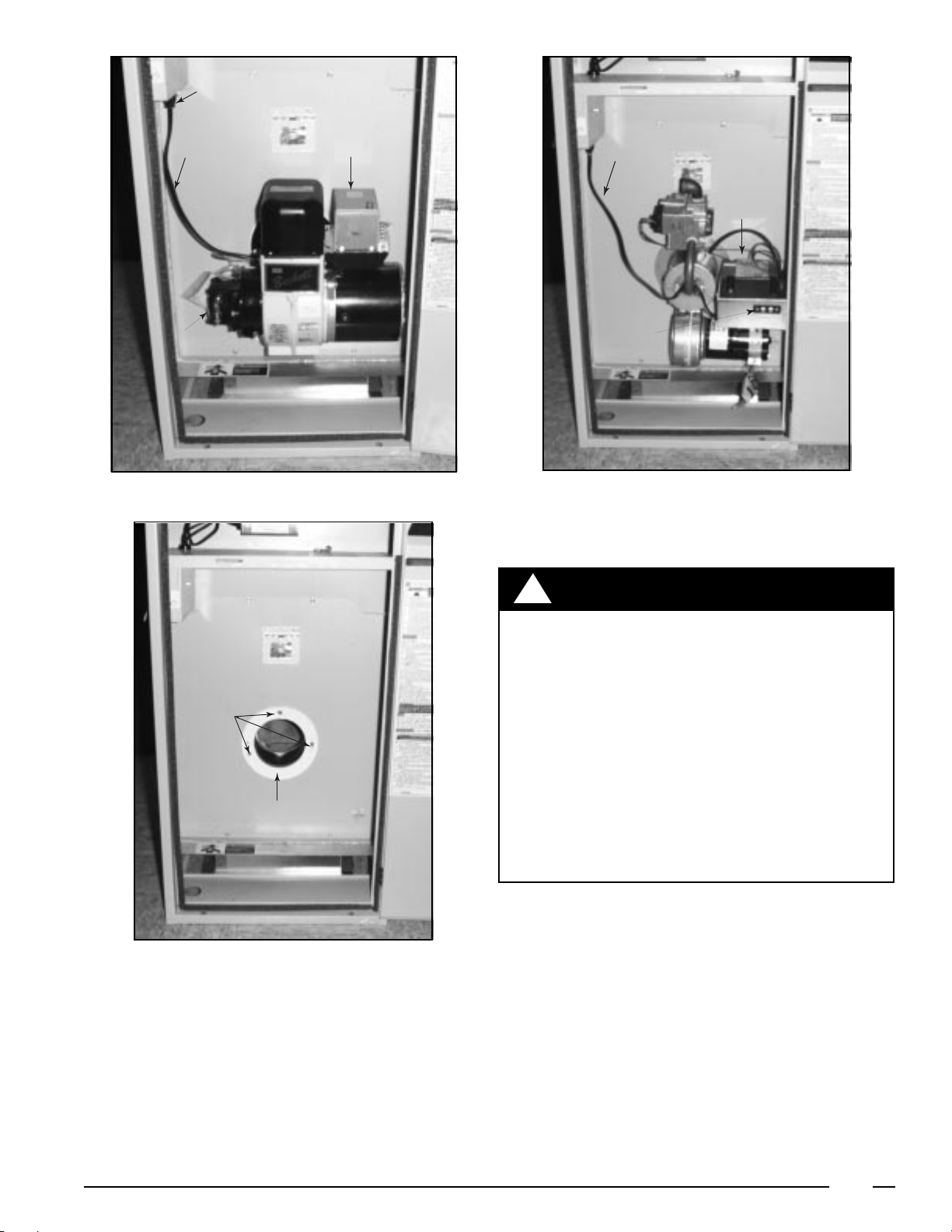
Before installing the power gas burner, removal of present
burner is required. (See Figure 2.)
1. Shut off electric power supply to furnace. Remove
power cord from 120v receptacle, remove low voltage
(thermostat) wiring from primary control connections.
2. Shut off fuel supply to burner, close line or tank valve if
applicable. Disconnect fuel line at inlet fitting on burner
pump and remove fuel line.
3. Loosen and remove the three (3) 2/16" hex nuts, and
remove the burner.
4. Inspect the combustion chamber and heat exchanger
for cracks, corrosion, or soot. If signs of sooting are
present, the heat exchanger should be cleaned to insure
proper draft.
Installing Gas Burner
1. Place new burner gasket on mounting plate. (See Figure
3.) Insert burner tube into heat exchanger through
mounting flange. Mount burner on studs, making sure
burner will pull up tight to flange, and fasten to mounting
flange using the three hex nuts.
2. Reconnect thermostat leads to appropriate connections
on burner. Attached power cord may then be plugged
into 120v receptacle.
Figure 1.
3. Connect gas piping and check for leaks.
a. Gas piping should be sized and installed in accordance
with local codes and utility regulations.
4. Thermostat - It may be necessary to change the heat
anticipator setting. Failure to do so could result in a wide
temperature fluctuation in home.
18
Page 19
120V Receptacle
Power
Cord
Fuel Line
Fitting
Figure 2.
Primary Control
Power
Cord
HSI
Control
Thermostat
Connections
Figure 4.
Mounting
Studs
Burner Gasket
Figure 3.
!
WARNING:
FOR YOUR SAFETY, WHAT TO DO IF YOU
SMELL GAS:
Do not try to light any appliance.
Do not use any electrical switch, do not use
any phone in your building.
Immediately call your gas supplier from a
neighbor's phone. Follow the gas supplier's
instructions.
If you cannot reach your gas supplier, call the
fire department. Should overheating occur or
the gas supply fail to shut off, disconnect the
power at the main circuit breaker and then see
"To Turn Off Gas Appliance.
19
Page 20

Operation — CMF-PG Series
FOR YOUR SAFETY READ BEFORE LIGHTING OR
OPERATING.
!
W ARNING:
If you do not follow these instructions exactly,
a fire or explosion may result causing property
damage, personal injury or loss of life.
1. This appliance does not have a pilot. It is equipped with
an ignition device which automatically lights the burner.
Do not try to light the burner by hand.
2. BEFORE LIGHTING OR OPERATING: smell all around
the appliance area for gas. Be sure to smell next to the
floor because some gas is heavier than air and will settle
on the floor.
WHAT TO DO IF YOU SMELL GAS:
• Do not try to light any appliance.
• Do not touch any electric switch, do not use the phone.
• Leave the building immediately, then call your gas
supplier.
• If you cannot reach the gas supplier, call the fire
department.
3. Use only your hand to push in and move the gas control
lever. Never use tools. If the lever will not push in by
hand, don't try to repair it, call a qualified service
technician. Force or attempted repair may result in a fire
or explosion.
4. Do not use this appliance if any part has been under
water. Immediately call a qualified service technician to
inspect the appliance and to replace any part of the
control system and any gas control which has been
under water.
5. Should overheating occur, or the gas supply fail to shut
off, turn off the manual gas valve to the appliance.
OPERATING INSTRUCTIONS – CMF-PG
Series with PGB-DI Direct Ignition Burner
1. STOP! Read the safety information above.
2. Set the thermostat to OFF or to its lowest setting.
3. Turn off all electric power to the appliance.
4. This appliance is equipped with an ignition device which
automatically lights the burner. DO NOT try to light the
burner by hand.
5. Turn the latch and open the furnace door.
6. Push in the gas control lever and move to OFF. DO NOT
FORCE.
7. Wait ten (10) minutes to clear out any gas. If you then
smell gas, STOP! Follow Section B in the safety
information above. If you don’t smell gas, go to the next
step.
8. Move the gas control lever to ON.
9. Close the furnace door and turn the latch.
10. Turn on all electric power to the appliance.
11. Turn the thermostat to ON and set to the desired setting.
12. If the appliance will not operate after one re-try, follow
the instructions in the “To Turn Off Gas To Appliance”
Section below and call your service technician or gas
supplier.
To Turn Off Gas to the Appliance
1. Set the thermostat to OFF or to its lowest setting.
2. Turn off all electric power to the appliance if service is to
be performed.
3. Turn the latch and open the furnace door.
4. Push in the gas control lever and move to OFF. DO NOT
FORCE.
5. Close the furnace door and turn the latch.
Operating Sequence
On a call for heat, the thermostat contacts close which
energizes the combustion blower motor. When motor operation reaches 80% of full rpm, the centrifugal switch,
located in the motor end cap, closes. A thirty (30) second
pre-purge cycle will occur before supplying power (24v) to
the gas valve.
20
Figure 5. Direct Ignition Gas Valve
When the ignition control is powered, the ignition sequence
is started with an internal safe start check. After the safe start
check is complete, the control will initiate a timed ignitor
warm-up period. During this time, the ignitor is heated to
ignition temperature. When the warm-up period is completed, the control will open the gas valve for a timed trial
ignition period. The ignitor will light the gas and detect the
presence of flame using the flame rectification principle. If
flame is detected the control will keep the gas valve open
until the call for heat is completed. If no flame is detected, the
control will close the gas valve at the end of the trial for
ignition period.
Page 21

The ignition control is equipped with a relight feature. If the
flame is extinguished during the run cycle, the control will
close the gas valve and repeat the ignition sequence as
previously described. Once in lockout, the control can be
reset by interrupting the 24 VAC power. This can be easily
accomplished by setting the thermostat below room temperature for at least forty-five (45) seconds, and then returning it to desired setting.
If adjusting the thermostat does not reset the ignition control,
turn power to the appliance off for forty-five (45) seconds,
and then turn it back on.
NOTE: If the gas control has been replaced or serviced,
lighting may not be satisfactory until air has been purged
from the gas line or the gas input and combustion air have
been adjusted.
Checking Natural Gas Input
Check the label on the burner to be sure the burner is
equipped with orifices for type of gas being used. Alternate
orifices are in bag attached to the burner. Instructions for
changing orifices are covered later herein.
To check the input, time the dial on the meter for one
revolution while the burner is operating. Be sure to isolate
all other gas consuming appliances except pilots. If the time
varies more than 5% from the times shown on the chart,
check the gas pressure according to the procedure stated in
GAS BURNER CONTROLS. If the pressure reading
matches the pressure shown on the chart; check to be sure
the proper burner orifice is being used. Further gas problems should be referred to the local gas supplier. Natural gas
varies in BTU value from 950 to 1,050 BTU per cubic foot.
The chart is based on natural gas at an average of 1,000
BTU per cubic foot, burner manifold pressure of 3.5" W.C.
and meter dial size of 1 cubic foot.
Adjusting the Burner
1. Air shutters are factory preset for installation in a given
furnace. (See Figure 15) Local conditions may require
fine tuning. Rotate the air shutter disc at the left of the
burner housing to adjust the combustion air. Rotate the
disc counterclockwise to increase combustion air. Rotate
the disc clockwise to decrease combustion air.
The combustion air for the power gas burner is taken from
the outside of the manufactured home.
Operating at high altitudes — for operation at elevations
of more than 2,000 feet above sea level, the input should be
de-rated 4% for each 1,000 feet above sea level by reducing
orifice size, or decreasing the manifold pressure.
1. Observe combustion flame through observation door on
CMF series furnaces immediately after burner is placed
in operation. Yellow flame tips should be visible above
combustion chamber.
2. Burner should run quietly. Excessive updraft may cause
burner to rumble; rotate disc to decrease air supply.
(CAUTION: See Note below.)
3. After checking the flame pattern and for noise level, lock
disc in position by tightening slotted head screw.
NOTE: It is very important that air supply be ample without
decreasing efficiency of burner. An inadequate amount of
air can cause carbon monoxide (CO). The carbon dioxide
(CO2) content of the flue products should be in the range of
8.0 to 9.0 percent for natural gas and 9.0 to 10.0 percent for
LP gas.
Adjusting Heat Distribution
1. Set the room thermostat for the desired room
temperature.
2. Balance the heat distribution by adjusting the register
openings.
Burn er BTUH Burn er Ti me Per
Model Input Orifice Rev.
PGB-1 90,0 00 No. 16 40 s ec.
PGB-2 75,0 00 No. 20 47 s ec.
Table 1.
Checking LP Gas Input
LP gas installations are not usually supplied with meters for
determining the amount of gas used. The chart shows the
approximate time required per dial revolution if a meter is
used that is calibrated for cubic feet delivery. The chart is
based on LP gas at an average of 2,500 BTU per cubic foot,
burner manifold pressure of 10" W.C. and meter dial size of
1 cubic foot.
Burn er BTUH Burn er Ti me Per
Model Input Orifice Rev.
PGB-1 90,0 00 No. 36 98 sec.
PGB-2 75,0 00 No. 40 117 s ec.
Table 2.
LOCKING
SCREW
Burner Model Air Setting
PGB-1 G
PGB-2 D
PGB-3 C
Figure 6. Air Shutter Adjustments for
Power Gas Burner
PGB Basic Air Shutter
Settings
To check combustion
air openings: Insert air
guage vertically into the
blower, the gauge
should stop within the
range shown in the
chart. Make sure the
shutter is securely
locked. See Installation
Manual.
21
Page 22

Air Supply for Sealed Combustion
1. Close and latch burner access door to complete the
outdoor combustion air passage.
2. If the space below the home is enclosed, be sure a vent
or duct of at least 18 square inches of free area is
provided from the outside to provide sufficient air for
combustion. Make sure the combustion air duct extends
through the floor and is unobstructed.
Gas Burner Controls (Direct Ignition Series)
Combination Electric Gas Valve and
Pressure Regulator
The combination electric gas valve and pressure regulator
performs several functions. The gas valve control lever has
two positions. The OFF position completely shuts off the gas
supply. The ON position allows gas flow through the
redundant gas valve when it is energized electrically.
Gas to LP Conversion
This gas fired heating appliance was shipped from the
factory for use with natural gas. However, the appliance can
be converted to be used with LP gas. Use the following
procedure for gas conversion of the burner.
Remove the Burner Assembly:
1. Follow instructions “To Turn Off Gas To Appliance.”
2. Shut off gas supply at meter.
3. Disconnect gas burner electric cord, gas piping to burner,
and thermostat leads.
4. Remove three (3) hexagon nuts holding burner in place.
Reassemble Appliance:
1. Reassemble the burner assembly into the furnace.
2. Reconnect the gas piping and electrical wires to the gas
valve.
3. Open the manual shut-off valve and follow the “Operating
Instructions” as outlined previously in this manual to put
the furnace into operation.
Centrifugal Switch
The electric motor for the blower which supplies combustion
air to the burner is equipped with a centrifugal switch wired
in series with the burner controls. This switch is normally
open until the speed of the blower motor closes it thereby
powering the burner controls. The burner controls will not
function until the blower motor is operating at full speed.
Firing Rate Conversion
The rated firing rates of the CMF80 convertible furnaces
(PO & PG) can be adjusted from the factory setting of
75,000 BTU/hr.
The firing rate can be changed to either 65,000 BTU/hr. or to
90,000 BTU/hr. using the appropriate certified NORDYNE
conversion kit installed by a NORDYNE distributor or Service PRO. See the Replacement Parts Listing for the appropriate kit number to order.
Change the Main Burner Orifice:
1. Disconnect inlet pipe union at burner. Disconnect
burner power cord.
2. Disconnect the two wires leading to gas control valve.
3. Remove three (3) bolts from U-shaped manifold plate
and orifice assembly.
4. Remove the main orifice and replace it with the alternate
fuel orifice supplied in the plastic bag with this burner.
Change the Pressure Regulator:
1. Remove the regulator converter and its black cover
located on top of the gas valve and invert. (See Figure
16 — For LP, the red ring will be located at the bottom
and the “LP” stamping on the converter will appear right
side up.)
2. Screw converter back into the regulator, hand tight plus
1/8 turn, and replace the black cover onto the converter
top to protect the threads.
Figure 7. Natural Gas Configuration
22
Page 23

TERMINAL HOUSING
TERMINAL BOARD
IGNITOR
Gas Gun Furnace Wiring Diagram
CONTROL
MODULE
IND
L1
HSI
HSIG
L2
W
PSI
FSI
GV
PSO
FSG
C
BLUE
BLUE
BLACK
BLACK
WHITE
RED
RED
RED
GREEN
BUSHING
BLACK
BLACK
BUSHING
BLUE
GROUND
SCREW
BURNER ELECTRICAL BOX
YELLOW
CLOSED END
CONNECTOR
BLACK
WHITE
BLACK
BLACK
RED
RED
BLACK
BLACK
BUSHING
120V
N
YELLOW
24V
TO COMBUSTION MOTOR
L1
BUSHING
23
LINE CORD
GAS VALVE
Page 24

N
Motor
Recpt.
Sw.
Door
Speed
Blower
Wire
Color
Blower
Low
Med.
High
120V
G
L1
Red
Blue
Black
Aux. Limit
Blk
Control
Fan & Limit
(see table)
is the Medium Speed
Blower Speed Setting Shown
Blk
Manual Sw.
Blk
Fan Sw.
Sw.
Aux.
Sw.
Limit
105 C wire or equivalent.
with the appliance is replaced, use
If any of the original wire supplied
Burner Plug
1
Red
1
1
Red
Motor
Blower
Blue
2
2
Blue
Blk
1
Wht
Receptacle
1
1
Wht
Blk
Wht
Blk
6
5
4
3
6
5
4
3
L1
G
120V N
Switch
Door
Wht
Brn
Brn
Motor
Blower
Capacitor
Represents Control Box
CMF Wiring Diagram
St. Louis, MO
067A-0298
Specifications and illustrations subject to change without notice
and without incurring obligations. Printed in U.S.A. (11/98)
 Loading...